1. Introduction
The exhaustion of fossil fuels, the environmental pollution from fuel emissions, and the fuel cost savings have greatly promoted the development of new technologies such as renewable energy electricity, hybrid power system for vehicles, energy saving, and emission reduction. As the main equipment of petroleum and gas drilling exploration, the oil drilling rig is configured with total power capacity in 2 to 3 MW diesel engines or diesel generator sets to supply power to the working sets such as the draw-works, mud pumps, and the rotary table. A large drilling rig consumed diesel oil in quantity of about 100 tons in one month and brought great amounts of CO
2 emission [
1,
2]. In the drilling process, the drill stem is frequently put out of and run in the hole, which makes the load of the draw-works fluctuate wildly like pulses. The diesel engine capacity should be specified as three times to the average load power for the need of heavy pulse load in short time duration. Frequent load changing by large amounts causes a harmful impact on the engine. The hybrid power system with a peak load leveling function may be useful for solving the pulse load problem and for saving energy and reducing emission. Zhang et al. gave some experimental results but did not present the theoretical model of the peak load leveling analysis and fuel saving quantitative prospect [
3]. A piston accumulator composed of the oil storing cylinder and air vessel was adopted in the energy saving oil drilling rig to store the energy of the motor at idle time and recover the potential energy released by the drill stem when lowered [
4]. The study showed that it is possible to remove peaks of the rig power requirement by a flywheel kinetic energy recovery and storage (KERS) system and that linking to the electrical grid would supply enough power to operate the rig normally and have the potential to save energy cost [
5]. The new concept of hybrid power in the MW scale application is introduced to the oil well drilling rig for the first time in this paper. The hybrid power system combines the combustion engine and electric motor as the power for the driving chain. The energy storage system is crucial for the power system with a peak load leveling function in which the energy is transferred along the time dimension.
In the novel hybrid power system for a drilling rig, the electric motor/generator assembled in the compound chain box is the key to store the redundant power of the diesel engine in the valley load and release power to bear the pulse peak load. The hybrid energy systems have received more attention over the past decade [
6,
7]. The technology of hybrid electric vehicles has the advantages of lower fuel consumption, lower emissions, lower noise pollution, lower operating costs, smaller engine size, and longer operating life [
8]. Hybridization using the combined advantages of batteries and double layer capacitors has shown significant potential to absorb, store, and re-emit breaking energy when applied to suburban and regional duty cycles [
9]. It has been observed that ESSs are a viable solution to re-use regenerative energy with voltage stabilization and energy saving purposes in urban rail systems [
10]. We introduced the hybrid power concept into the drilling rig for petroleum and gas exploration for the first time.
Flywheels are electro-mechanical storage devices that store kinetic energy in a rotating mass so-called rotor coupled with an electric machine working as a motor in charging or a generator in discharging [
11,
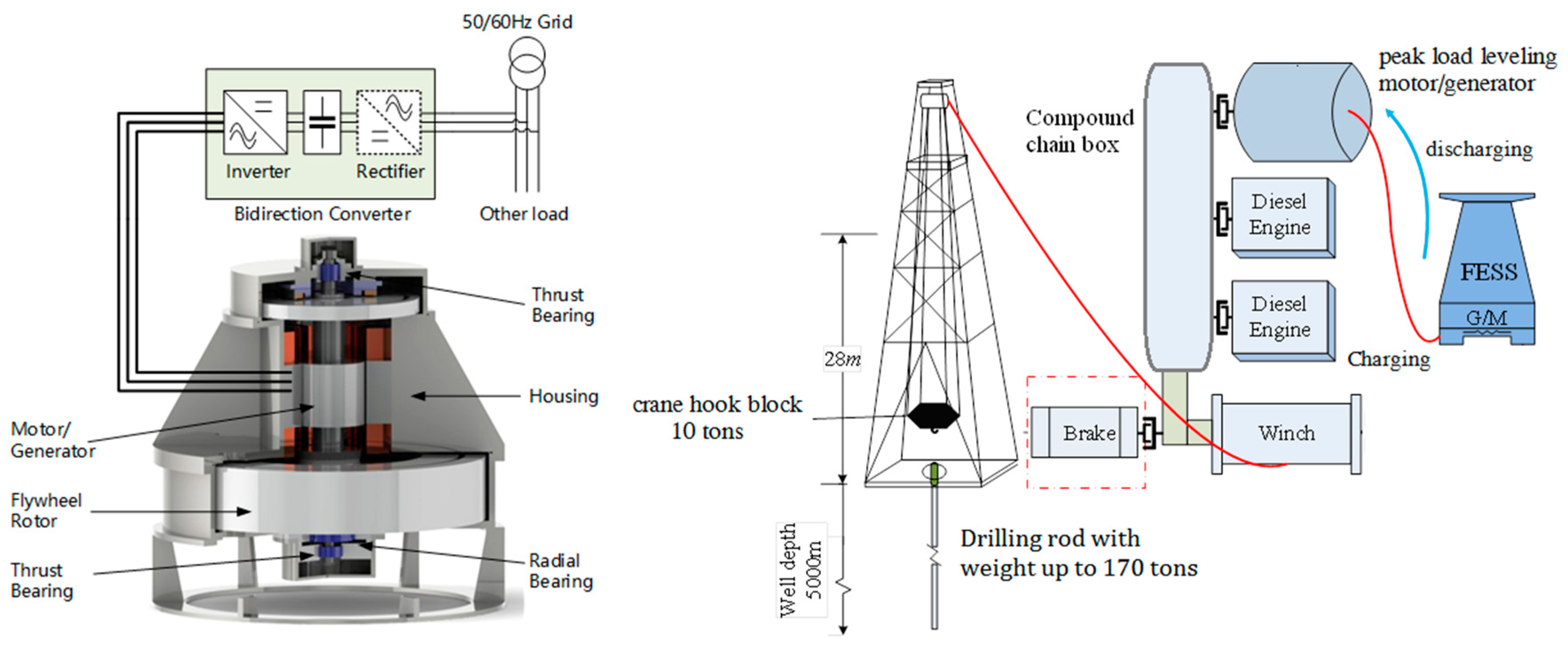
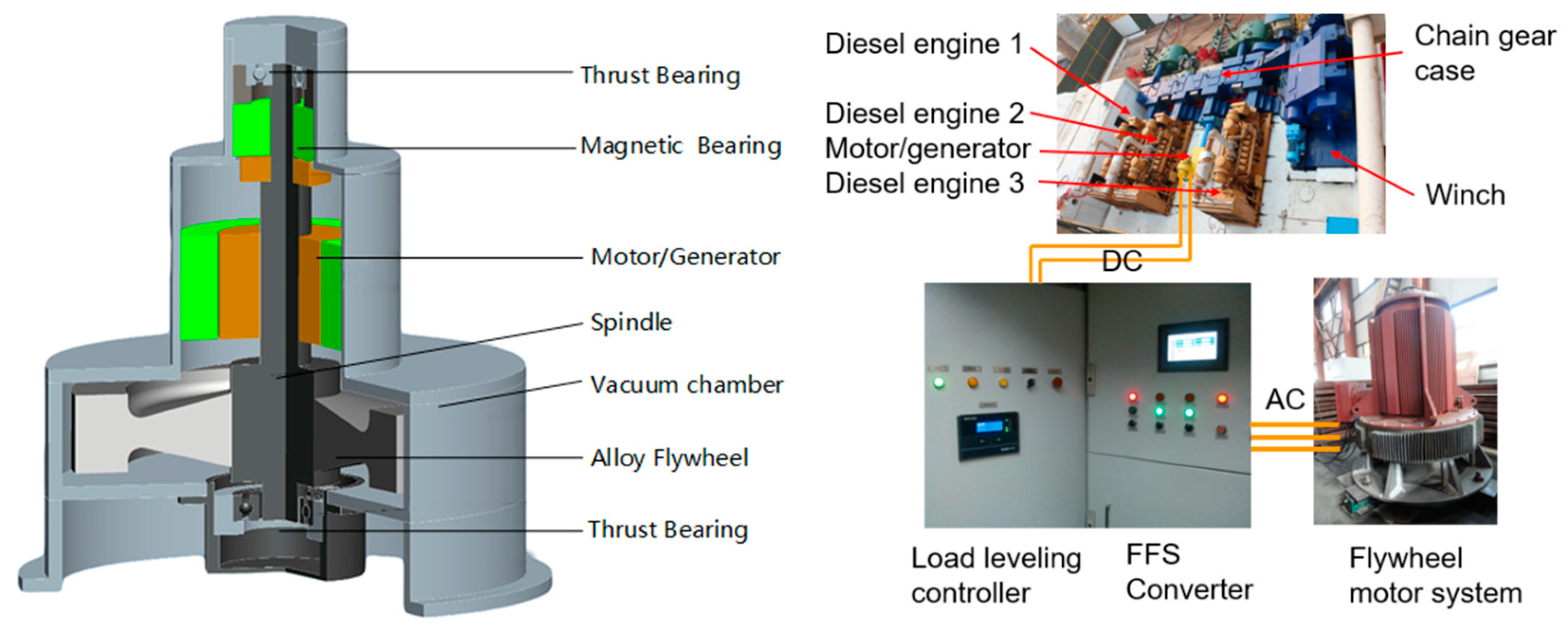
12]. As show in
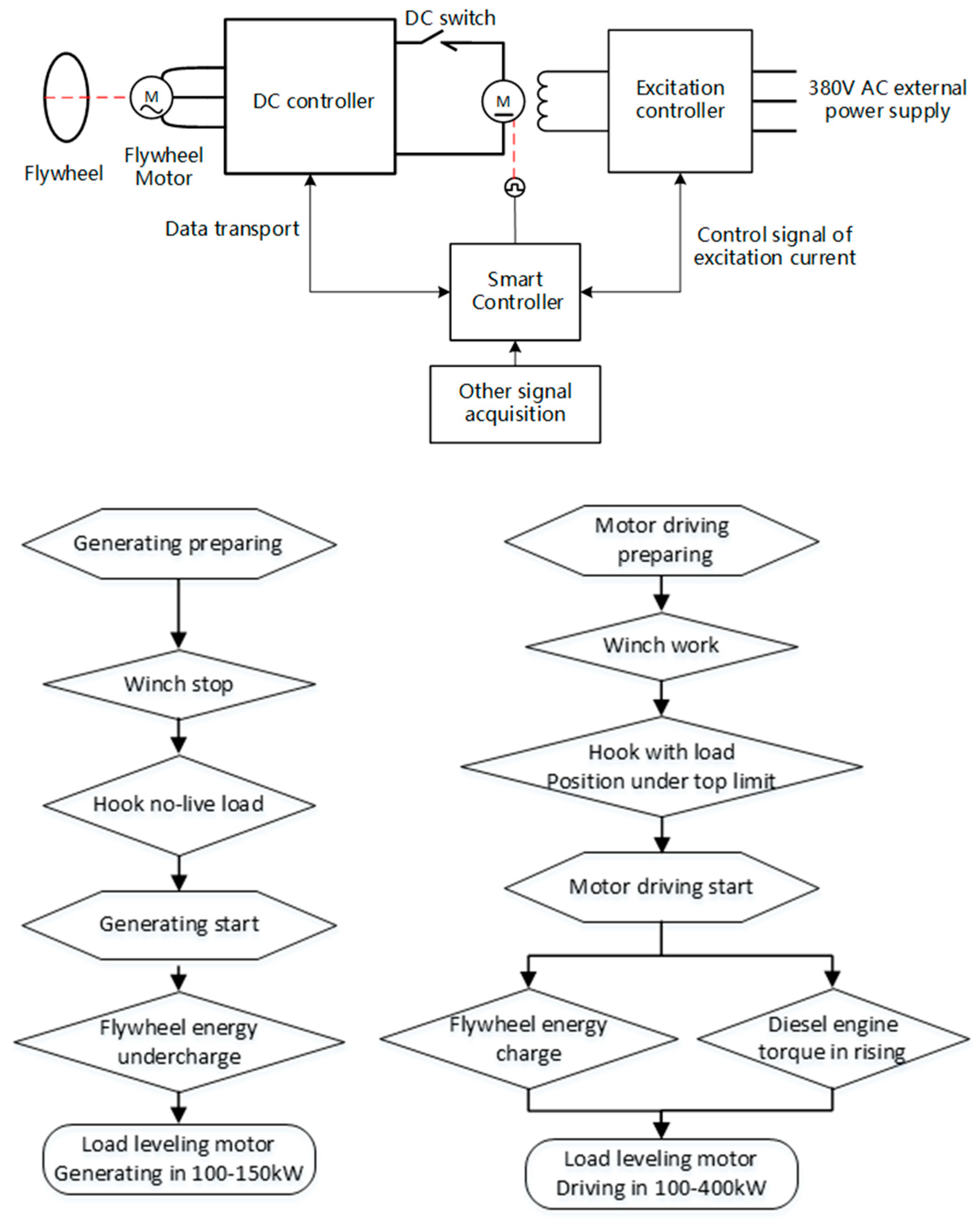
Figure 1, a typical flywheel energy storage system consists of a flywheel supported by a rolling-element bearing connected to a motor–generator. The flywheel and sometimes motor–generator may be enclosed in a vacuum chamber to reduce friction and reduce energy loss. To reduce friction, magnetic bearings are sometimes used instead of mechanical bearings. The motor-generator is driven in acceleration or deceleration by the bi-directional converter as power electronics interface, which controls the flow of the energy between the power source, the load, and the flywheel.
They present good features regarding high efficiency (around 90% at rated power), long cycling life, and high power. The advantageous features make ESS based on flywheels a very suitable option for different applications such as wind power smoothing, transportation, or quality power applications [
13,
14,
15,
16]. The Flywheel Energy Storage System (FESS) is used as an energy regeneration system to help with reducing peak power requirements on rubber tyred gantry (RTG) cranes that are used to load or unload container ships [
17]. A variable speed generator is integrated to the simulation-hybridized RTG. The simulation results reveal that the total energy savings exceeded 30% relatively to conventional RTG [
18].
In the power train and load system of the drilling rig, the load frequently oscillates in a large amplitude in terms of putting out the hole or running in the hole. The oscillation makes the diesel engine work uneconomically with a heavier load or a lighter load than its rated economic output, and shortens the life of the diesel engine. Therefore, the flywheel energy storage system is used in the hybrid power system for peak load leveling purposes. As shown in
Figure 1, the peak load leveling system consists of two diesel engines, a compound chain box, a peak load leveling motor/generator (PLL M/G), a flywheel energy storage set, the control system, and the draw-works machine. In the light load cases, the diesel engine drives the flywheel to accelerate and store energy through the peak load leveling motor/generator (working as a generator) rotating with the compound chain box. Under the pulse heavy load, the flywheel decelerates and releases power into the chain driving system to bear the peak load through the peak load leveling motor/generator (working as a motor). Then, the diesel engine works in a nearly constant load condition. Furthermore, the capacity of the diesel engine could be set as 1.5 times the normal load instead of three times in the case of the traditional mechanical drilling rig. For example, a 400 kW engine in the hoisting tripping operation could substitute the 800 kW engine.
In the peak load leveling technology in the power system, the energy storage methods may be chemical battery, super-capacitor, or flywheel. The main feature of the flywheel energy storage system is that it charges and discharges at high rates as many cycles as up 1 × 10⁶ without performance decaying. The load energy density of super-capacitor limits the application for large energy using case. The load-oscillating period of the hoisting machine in the drilling rig is about 2 to 4 minutes, which makes it difficult to use the chemical battery. The wide scope of temperature in the wilderness of the oil drill work blocks the lithium-ion battery application. Therefore, FES was selected as the energy storage method in the present study.
The storage capacity of the power and energy as well as charging-discharging modes are fundamental for the design of the hybrid power system. The fuel consumption is an important indication for the practical application of the peak load leveling technology. The configuration, mode, and detail technical parameters of the hybrid power system with peaking load leveling of the oil-drilling rig are not published so far. The theoretical result in this paper provides the foundation and the guidance for the design of the new type of drilling rig to save energy through hybrid power application. To ensure that the engine smoothly runs for longer life, the load leveling experiments on the drilling rig verified the engine capacity configuration for energy saving.
3. Theoretical Model of Power with Peak Load Leveling
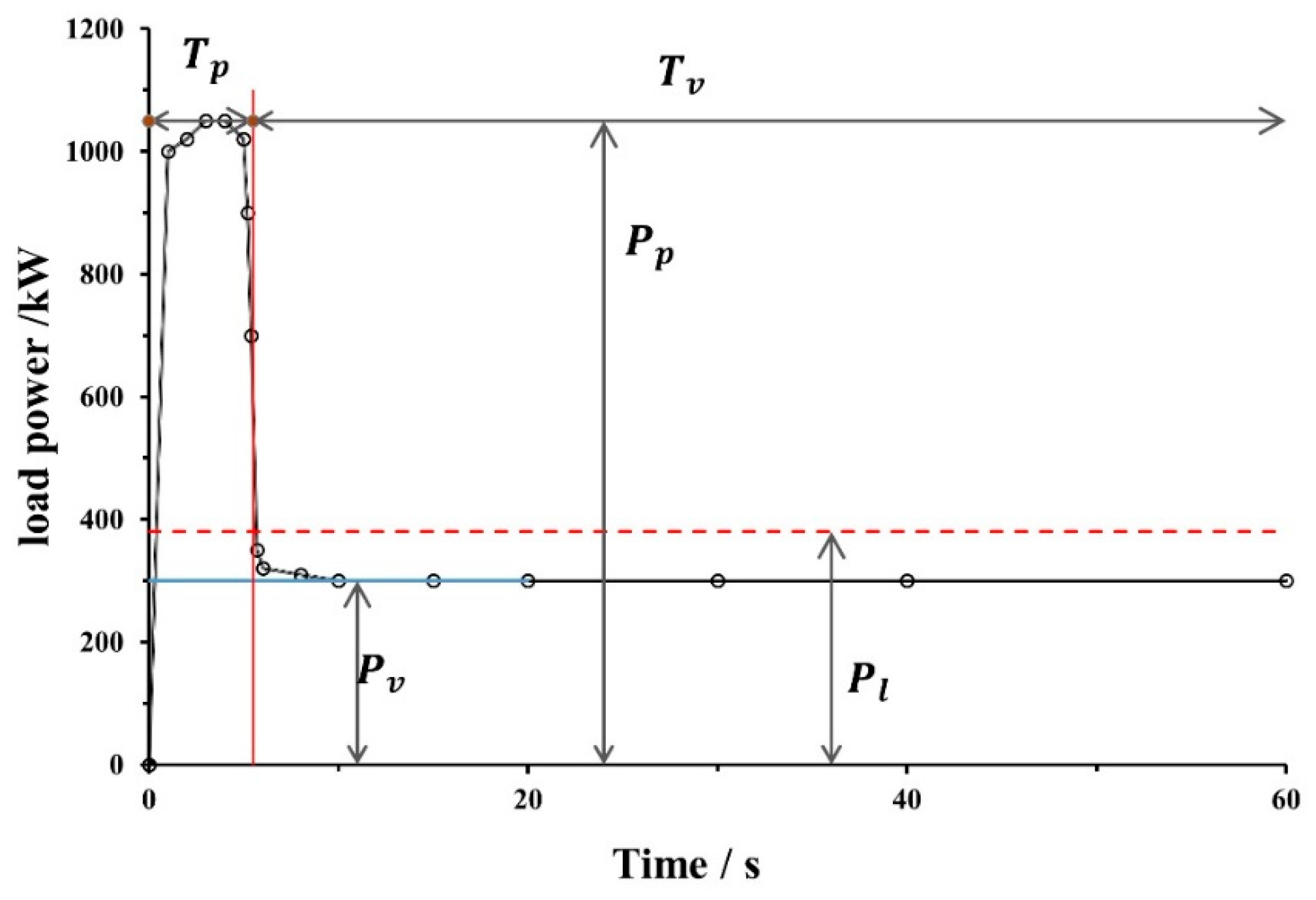
The periodic feature of load was assumed theoretically in simplification, as shown in
Figure 4. In the traditional running mode, the output of the diesel engine should fluctuate periodically in order to balance the load waving along the black curve in
Figure 4. On the contrary, the output of the engine could be constant, equal to
Pl (seeing pink dashed line in
Figure 4) in the new peak load leveling mode. In this mode, the energy storage system is utilized to balance the load fluctuation by discharging the power at the peak load and storing energy in the valley load. The peak load leveling is completed by the DC motor/generator system in addition to the power train. The DC motor/generator system is connected to the FESS through a DC bus. In the charging mode, the motor/generator driven by the diesel engine through the compound chain box generates DC electricity supplying into the FESS to accelerate the flywheel storing energy at a valley load. On the other hand, the motor/generator is driven by the DC current from FESS in the discharging mode. It works as a motor to release power to the chain transmission box to bear the sudden rise of the load. The theoretical parameters and their values used in the analytical peak load-leveling mode are shown in
Table 1.
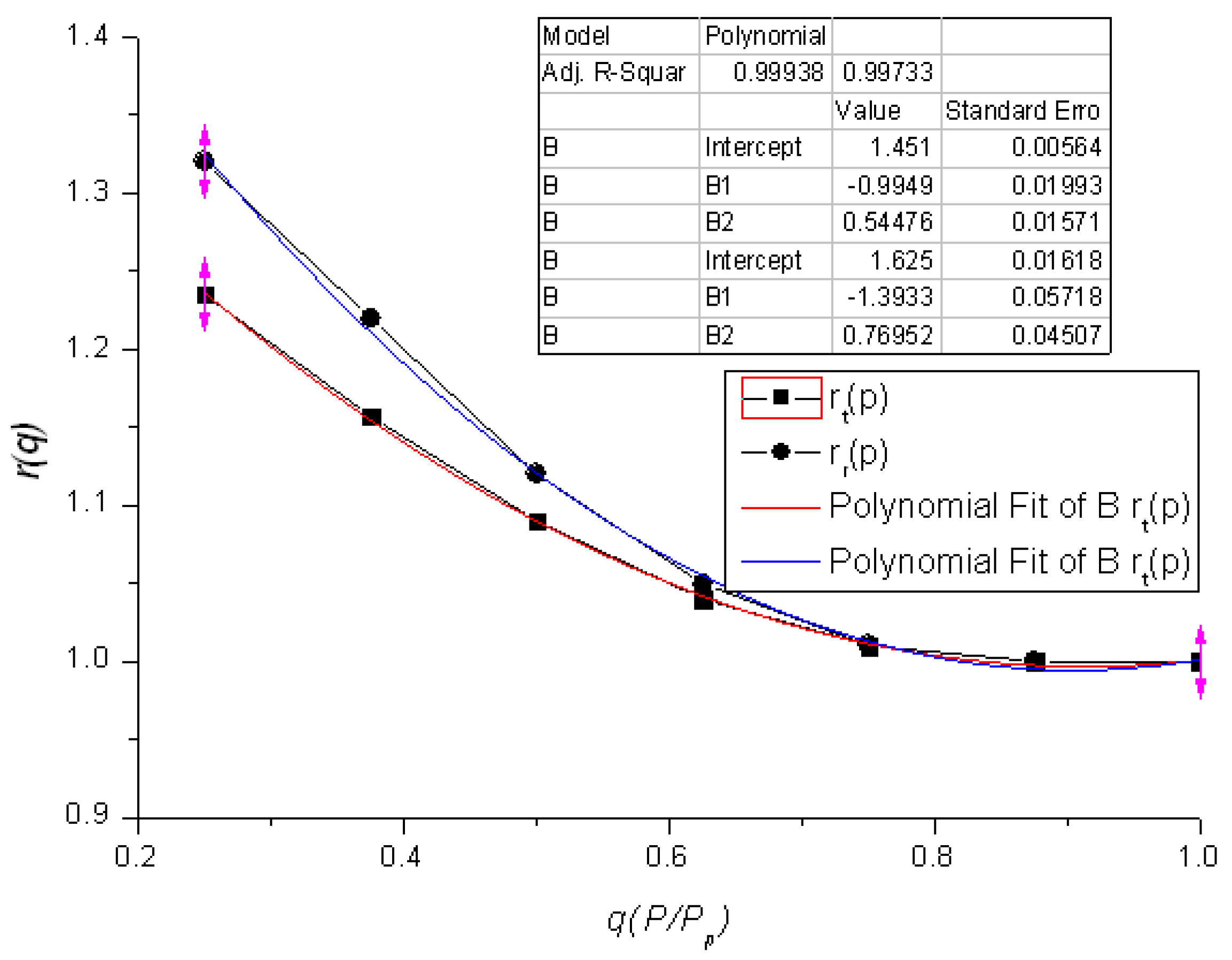
The fuel consumption varies with the increase of the power output of the engine. The theoretical scaling fuel consumption
rt can be expressed as a fuel consumption curve in
Figure 5 at different power outputs offered by the engine manufacturer. Considering that the fuel consumption will increase especially for the case of impact and periodical fluctuation load, another scaling fuel consuming curve
rr (5%–10% higher than
rt under low output) is assumed for theoretical analysis, which is shown in
Figure 5.
Due to the energy conservation law, the work of the diesel engine stored in the flywheel is equal to the energy released into the driving system from the flywheel through the peak load leveling motor, which means
Then the output of diesel engines in the load-leveling running mode is shown below.
The charging power of the load leveling system is shown below.
The discharging power of the energy storage load leveling system is shown below.
The power difference between charging and discharging is shown below.
The charging power is greater than the discharging power since , then the energy storage load leveling system works as a power reducer. The charging power is lower than the discharging power as , then the energy storage load-leveling system works as a power amplifier.
The fuel consumption in a cycle (
T = 120 s for example) for the peak load leveling running mode is shown below.
The fuel consumption in a cycle for the ordinary running without a peak load-leveling mode is shown below.
The fuel consumption ratio of two working modes is shown below.
3.1. Single Engine Mode
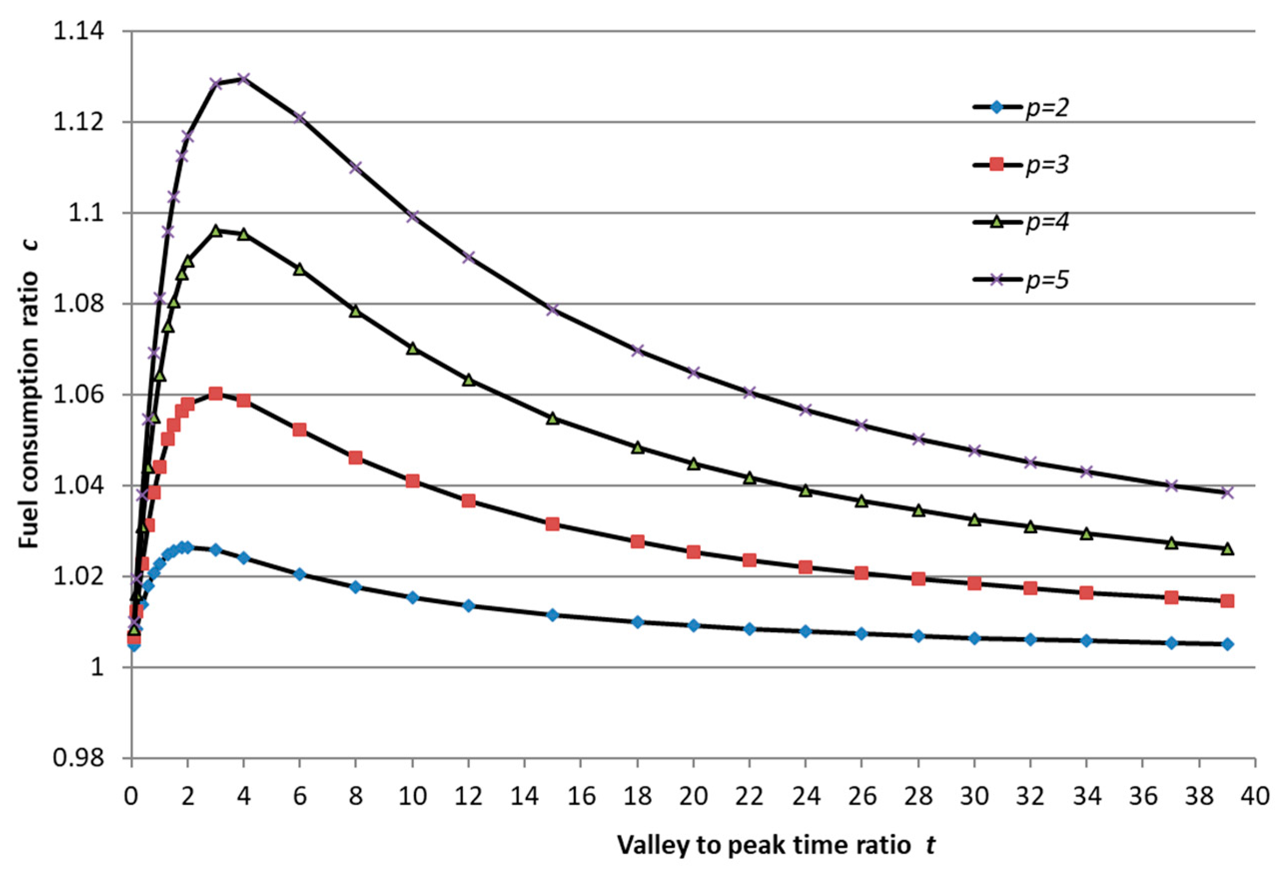
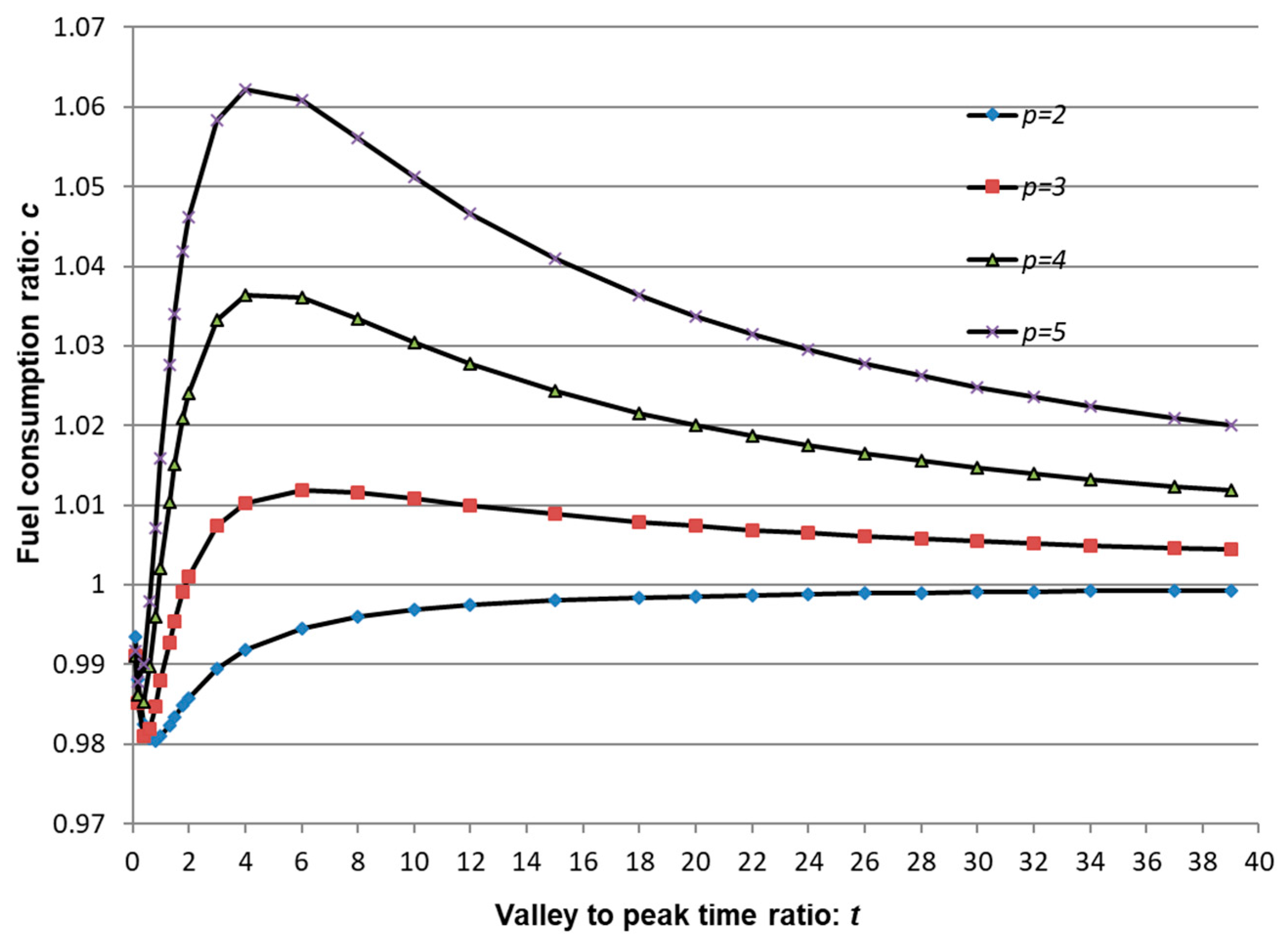
The maximum load is lower than 800 kW in one engine running mode. The speed of the diesel engine varies from 1300 to 1100 rpm frequently for putting out of the hole or running in the hole without peak load leveling. However, in the peak load-leveling mode, the engine output is nearly constant. The fuel consuming data are calculated under the assumption of the energy storage efficiency being 0.75 (; ). The energy storage load leveling system works as a power reducer at t < 1.3 and works as a power amplifier at t > 1.3.
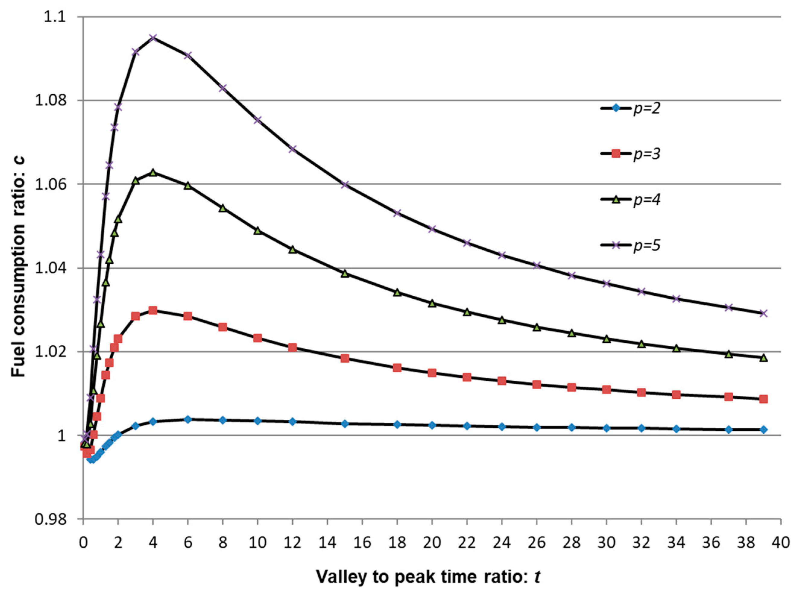
Figure 6 indicates that the fuel consumption ratio first increases and then decreases with the raising of the valley to the peak time duration ratio (
t), which arrives at its maximum valve when
t is equal to 2–4. The fuel consumption of the peak load-leveling mode is always greater than that of the traditional mode. The cost of the smooth running of the engine is more oil consumption. The fuel consumption becomes higher while the peak to valley power ratio increases. For example, the fuel consumption of the peak load leveling mode is 13% more than that of the traditional mode without peak load leveling in the case of
Pv = 160 kW and
t = 4. However, the fuel consumption increases only 2.5% if
Pv = 400 kW.
Figure 6 also indicates that the cost will fall off when the valley-peak time ratio is considerably large for the high peak-valley power ratio cases. For the cases in
Figure 6, the cost of fuel consumption raising 1% to 13% in the peak load leveling mode is paid for running a smooth engine.
The cost of peak load leveling becomes lower when the actual fuel consumption increases more than the theoretical value (
rt) for the low power output when the practical higher fuel consumption curve (
rr) is taken in the calculation. Improved energy storage efficiency also lowers the fuel cost of the peak-shaving mode. From
Figure 7, one can see that the fuel cost increase is smaller than 3% if the lower peak-valley power ratio (2 or 3) is selected in the peak load-leveling mode. Furthermore, the fuel may be saved for the case of
p = 2.0 (see
Figure 8) if the energy storage efficiency is 0.95.
The above discussion indicated that the higher fuel consumption was paid for the smooth output of the engine in most cases of the single engine with peak load leveling. However, the fuel may be saved if the energy storage efficiency is higher than 0.95 and the value of the peak-valley load ratio is 2.
3.2. Bi-Engines to Single Engine in the Peak Load Leveling
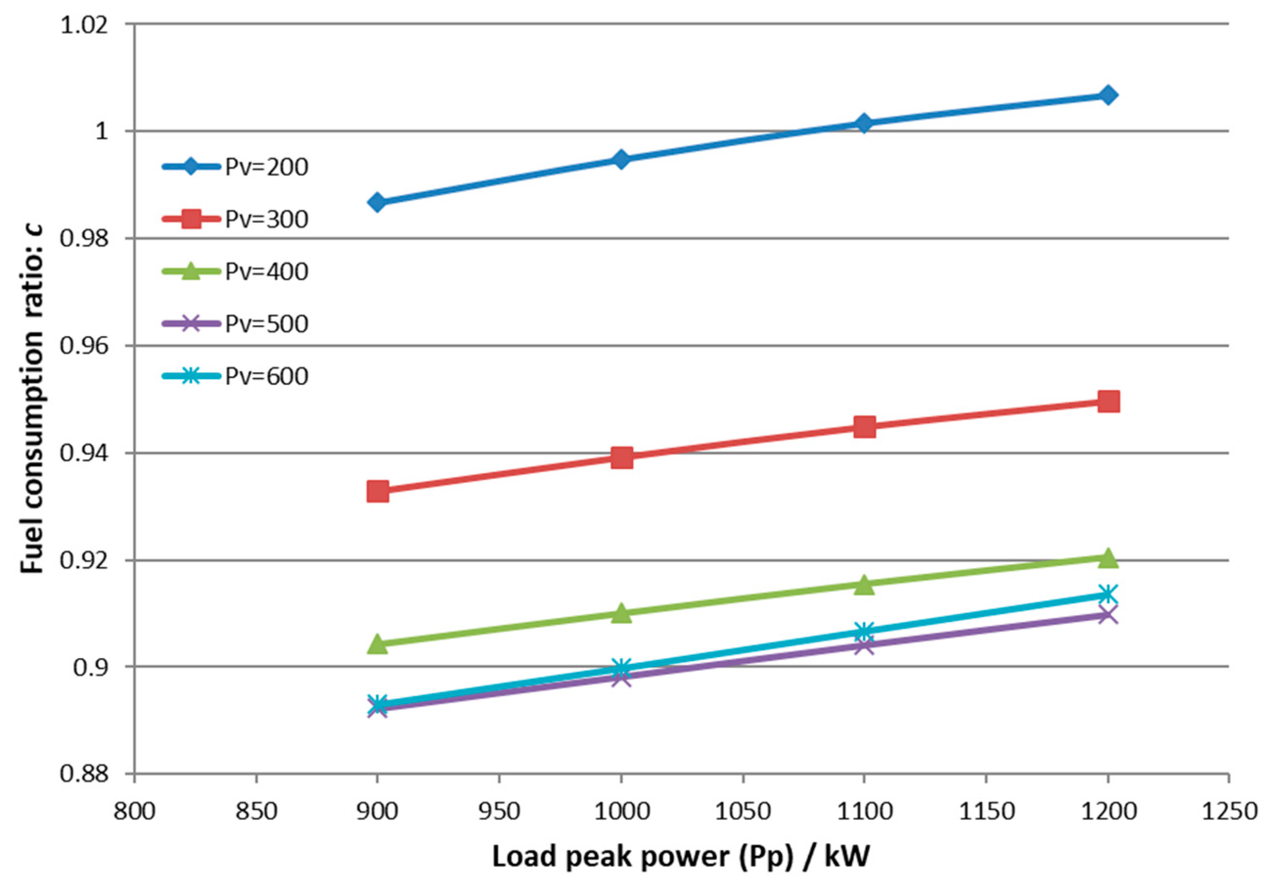
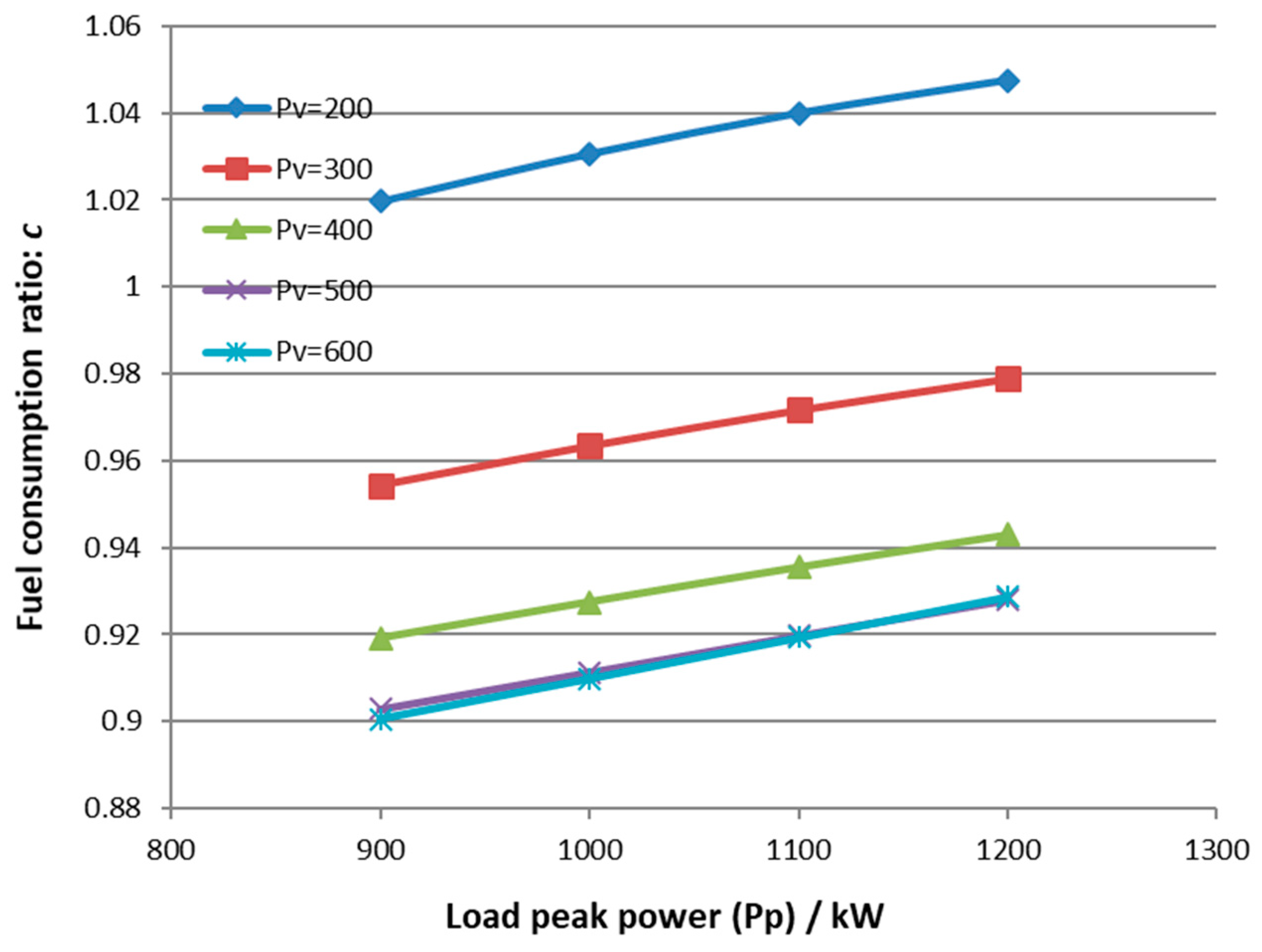
The two engines should run at the same time to share the heavy load if the maximum power exceeded 800 kW for the traditional mode. In the following analysis, the peak power varies from 900 kW to 1200 kW while the valley load varies from 200 kW to 600 kW.
The fuel consumption calculation in
Figure 9 depicts that the peak load-leveling mode not only makes the engine running stable but also leads to 1% to 8% fuel saving under the condition of the valley load being bigger than 350 kW.
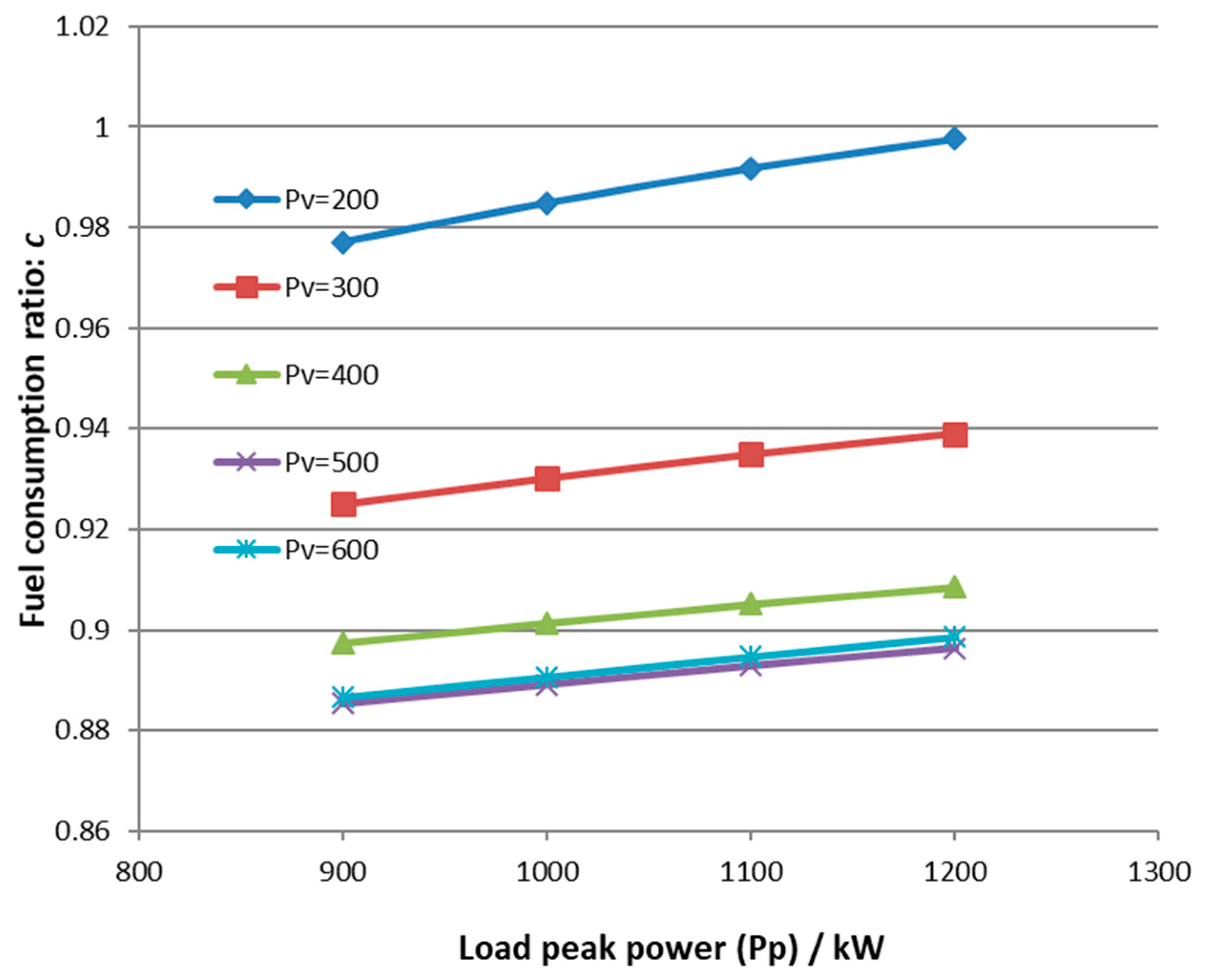
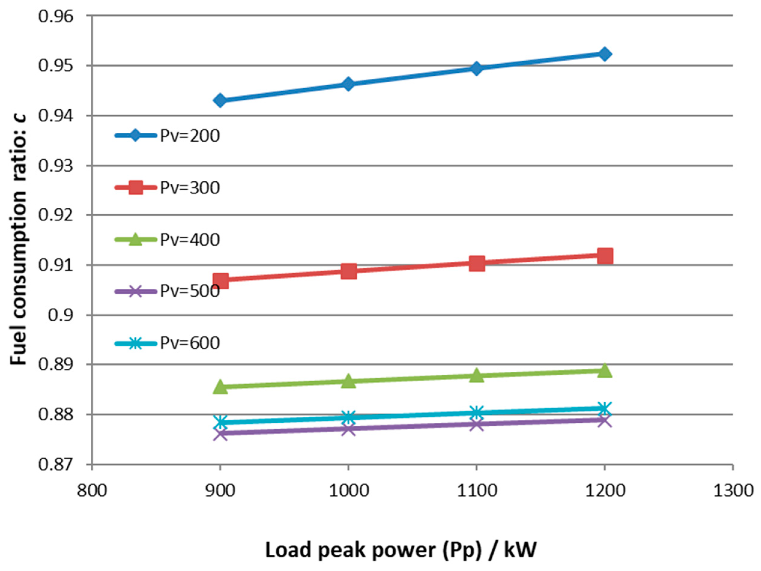
Figure 10 is the result of increasing the valley-peak time duration ratio, which means the sharp pulse characters of the load will lead to more fuel saving. Improving the efficiency of the energy storage set would also promote higher fuel saving as shown in
Figure 11 and
Figure 12. For the case of the sharp pulse load (
t = 39), the fuel save arrives at 10% since the valley load is 400 to 600 kW and the peak load is 900 to 1200 kW.
From
Figure 9,
Figure 10,
Figure 11 and
Figure 12, one can find that more fuel saving is possible with higher valley load, lower peak load, greater valley-peak time ratio, and higher energy storage efficiency. The analysis indicates that the fuel saving is realized by reducing the capacity of engine in the load leveling mode to half in the traditional mode for a pulse load condition. The small engine in the load-leveling mode should be competent to drive the hoister in coordination with the load leveling motor.
4. Experimental Verification of Peak Load-Leveling with FES
4.1. Parameters Selection
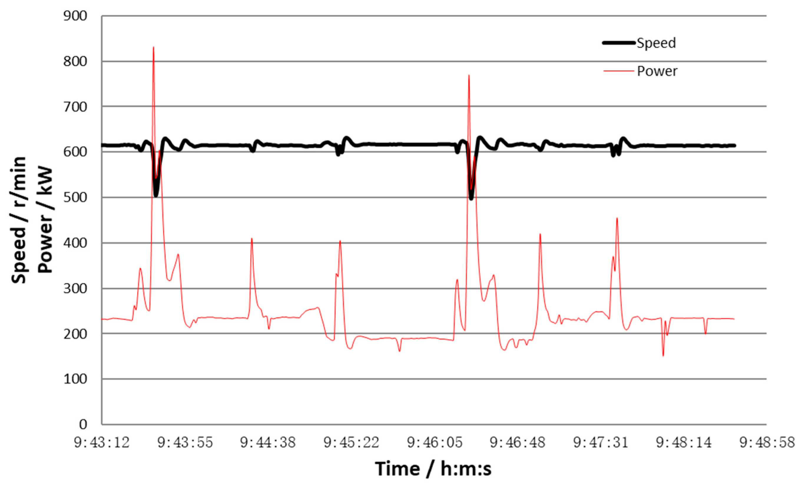
For the case of the oscillating load as shown in
Figure 2, the stable output of the diesel engine could be set to 350 kW. In the valley load time duration, the surplus power of 100 to 150 kW is stored by the FES system, which will discharge 400 to 450 kW to get a total of 750 to 800 kW peak output with the diesel engine to balance the peak load. The need energy is 8 to 9 MJ when the discharging time is set to 20 seconds. The kinetic energy of the flywheel should be 10 to 11 MJ, which is charging with 100 kW in 100 seconds. In the peak load-leveling running mode, the rated power of engine would be selected to 500 kW, which is smaller than about 40% of the normal power capacity of 800 kW. The case of running the drill rod in the hole is mainly considered in the experimental verification design. The available energy is set as 10 MJ. The charging power is 100 to 200 kW and the discharging power is 300 to 500 kW for the FES system [
19].
4.2. Flywheel Energy Storage System
The outline of the flywheel and motor is depicted in
Figure 13. The alloy steel flywheel with a diameter of 1200 mm and thickness of 140 mm has a moment of inertia as 222 kgm
2, weight of 1235 kg, and energy of 15.8 MJ at the speed of 3600 rpm [
20]. The flywheel motor is accelerated from 1800 rpm to 3600 rpm in the charging mode with a power of 150 kW. It is decelerated from 3600 rpm to 1800 rpm in a discharging mode with a power of 300 to 400 kW. The permanent magnetic bearing bears 90% to 95% of the weight of the flywheel generator shaft. Rolling bearings bear the radial load of the vertical flywheel and motor rotor shaft. A 400 kW permanent synchronous motor is employed for driving or generating. All the rotating parts of the FES system are sealed in the chamber, which is filled with helium for reducing the wind loss of rotating parts. The bi-directional converter controls the flywheel motor with IGBT power devices, which acts as the function of charging and discharging. The bi-directional converter is also connected to the load leveling motor with a DC 750 V Bus, working as the load or power source of the peak load leveling motor.
4.3. Peak Load Leveling Motor and its Controller
The peak load leveling motor is a DC motor (rated DC 750 V and power 400 kW) with electric excitation regulation and is connected to the compound chain box of the drill rig, as shown in
Figure 13. The peak load leveling motor works as a generator in the valley load to charge the FES system. The peak load leveling motor works as a motor to bear the peak load and obtain energy from the releasing of the FES system. The peak load leveling control system shown in
Figure 14 measures the power system data such as the speed of the engine, the peak load leveling motor speed, and suspending weight. It also calculates the power of peak load leveling and sends out the instruction of motor-driving, generating, charging, or discharging of the FES system.
4.4. Test Result of Peak Load Leveling
During running in the hole, the hoisting machine in braking, the engine had much spare power, and then charged the FES system up to the speed of 3000 to 3600 rpm. After the drilling rod was uncoupled from the hook block of the crane, the hoisting of the hook block to the top position (preparing for coupling with the drilling rod with an additional pipe) needed a pulse power of 500 to 800 kW. At that time, the FES system speed decreased from 3600–3000 rpm to 3000–1800 rpm and released power of about 300 kW instantly to the drive transmission system to mitigate the impact to the diesel engine.
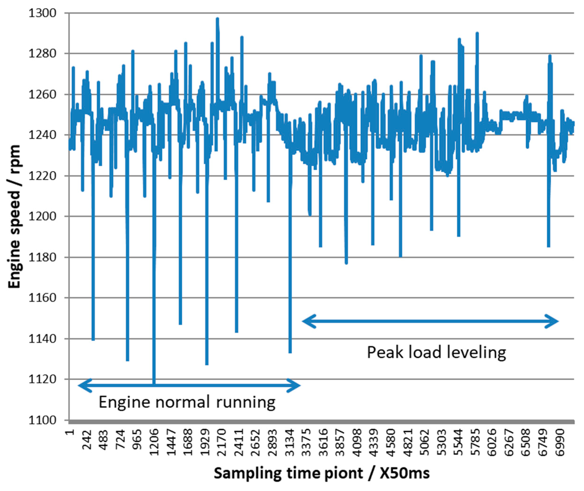
Figure 15 shows that the drop of the diesel engine speed was reduced by 50% in the peak load leveling running compared to that in the traditional running without peak load leveling. The emitting black smoke time duration also decreased to 1–2 seconds in the peak load-leveling run from 3–5 seconds in traditional running.
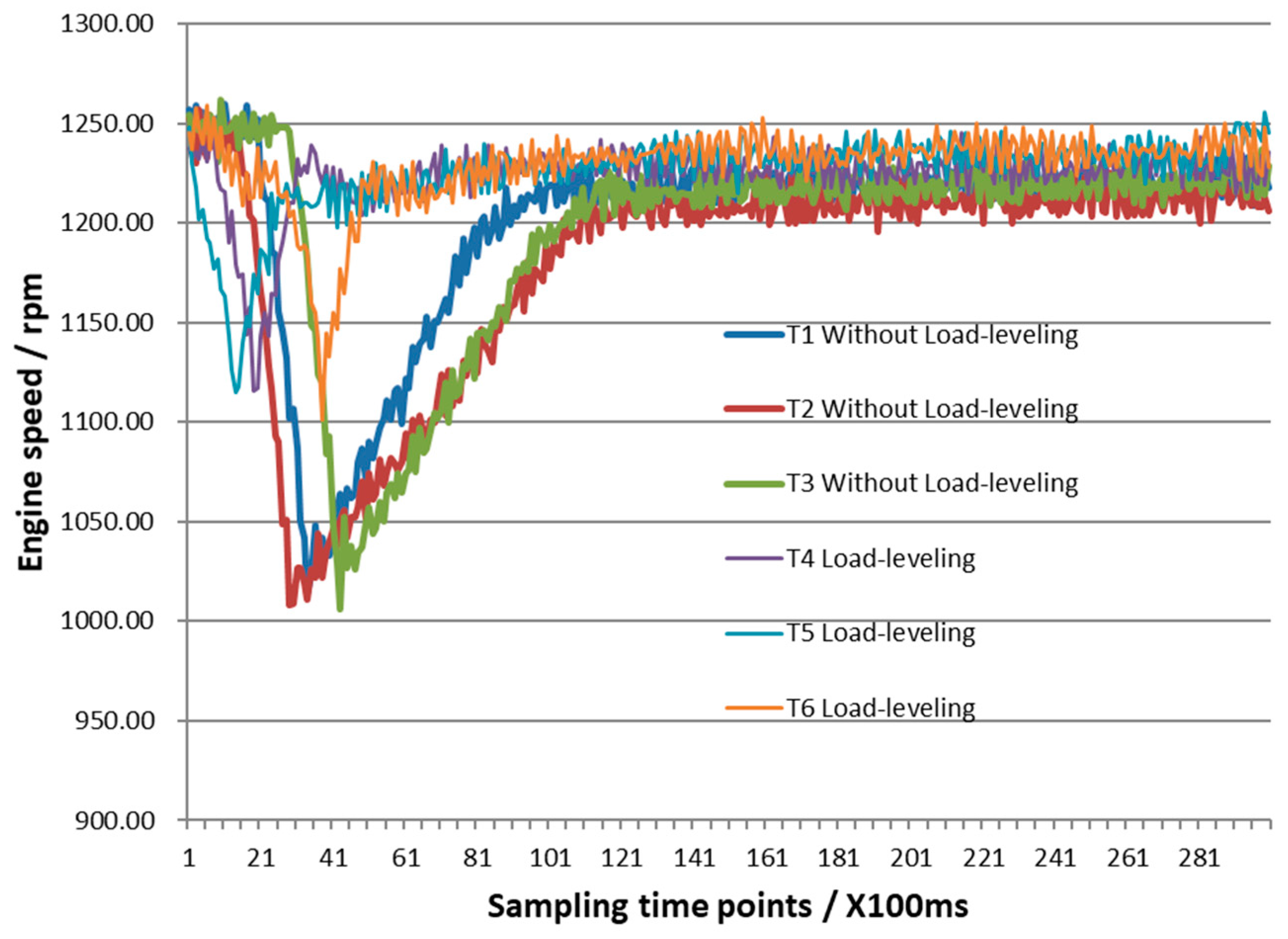
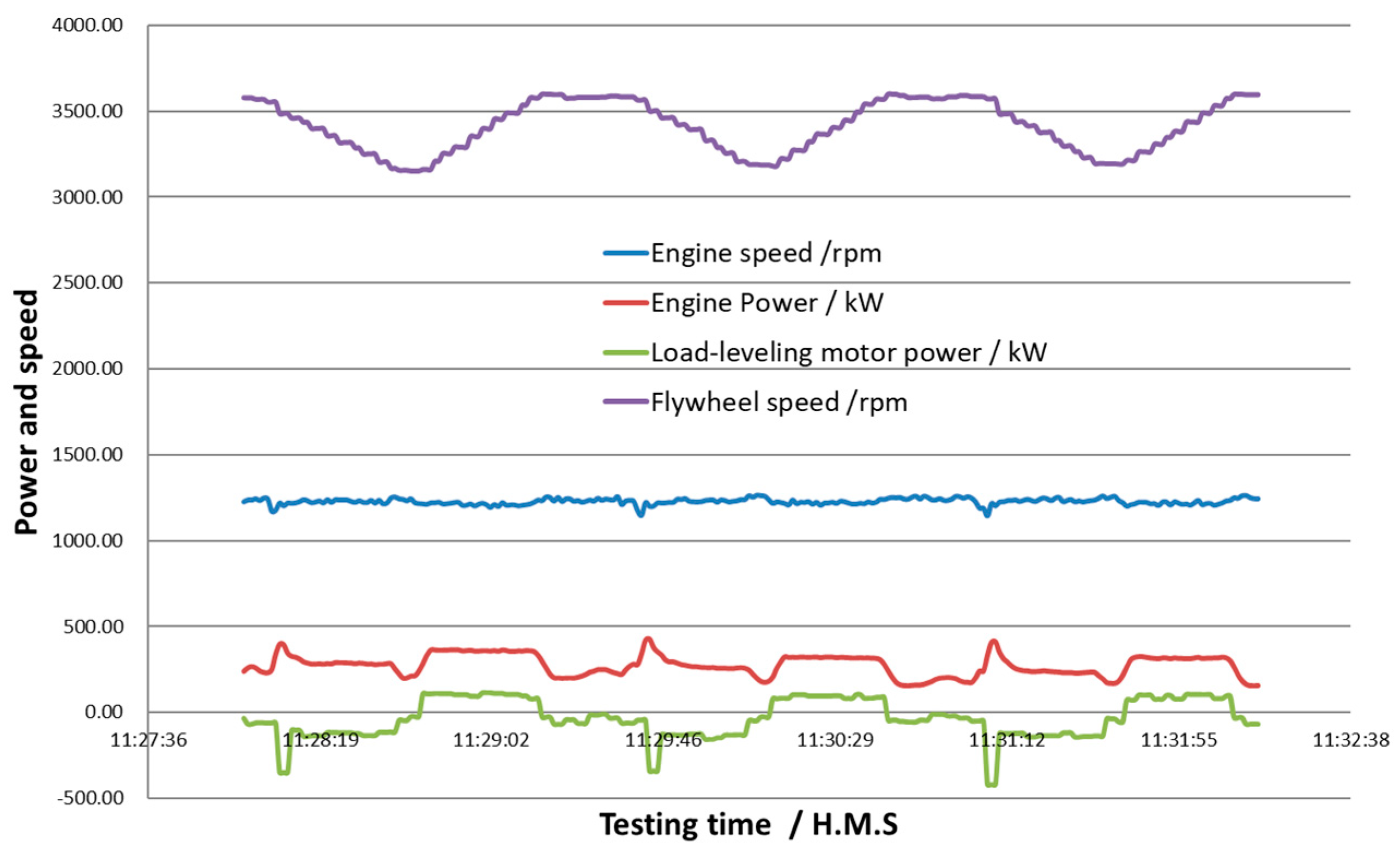
Six tests of lifting the hook block (with weight of 10 tons) were completed to obtain the engine power, speed, the flywheel speed, and the power of the peak load leveling motor. In the six tests, three tests (T4, T5, T6) were done in a peak load-leveling running mode and the other three tests (T1, T2, T3) were done without working of the peak load-leveling motor and FESS.
As shown in
Figure 16, for the case of tests T4, T5, and T6, the minus power of the peak load leveling motor means that the motor/generator worked as a motor to bear the load of hoisting the hook block together with the diesel engine using the discharged power from the flywheel energy storage system.
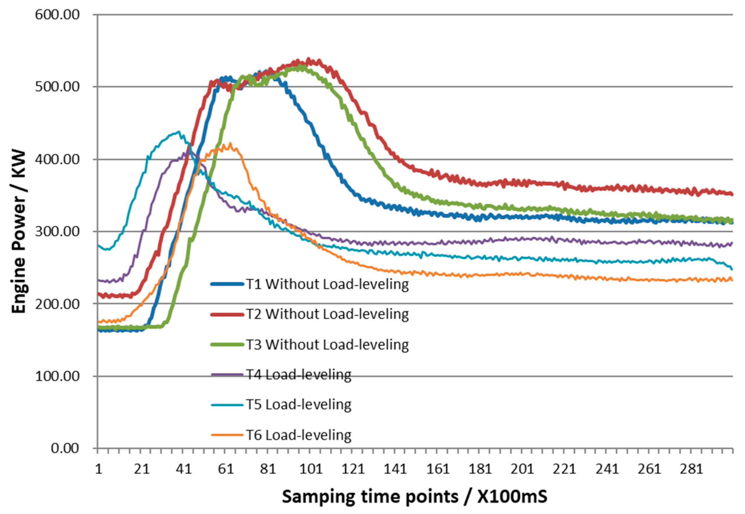
The comparison in
Figure 17 indicates that the output of the diesel engine became smaller and the power fluctuation duration became shorter when the peak load leveling motor/generator worked as a motor.
Figure 18 shows that the sharp drop of the engine speed with the load-leveling mode was only about 50% of that without a load leveling system. The detailed data verified that the peak load-leveling running made the engine work more smoothly under an impact load.
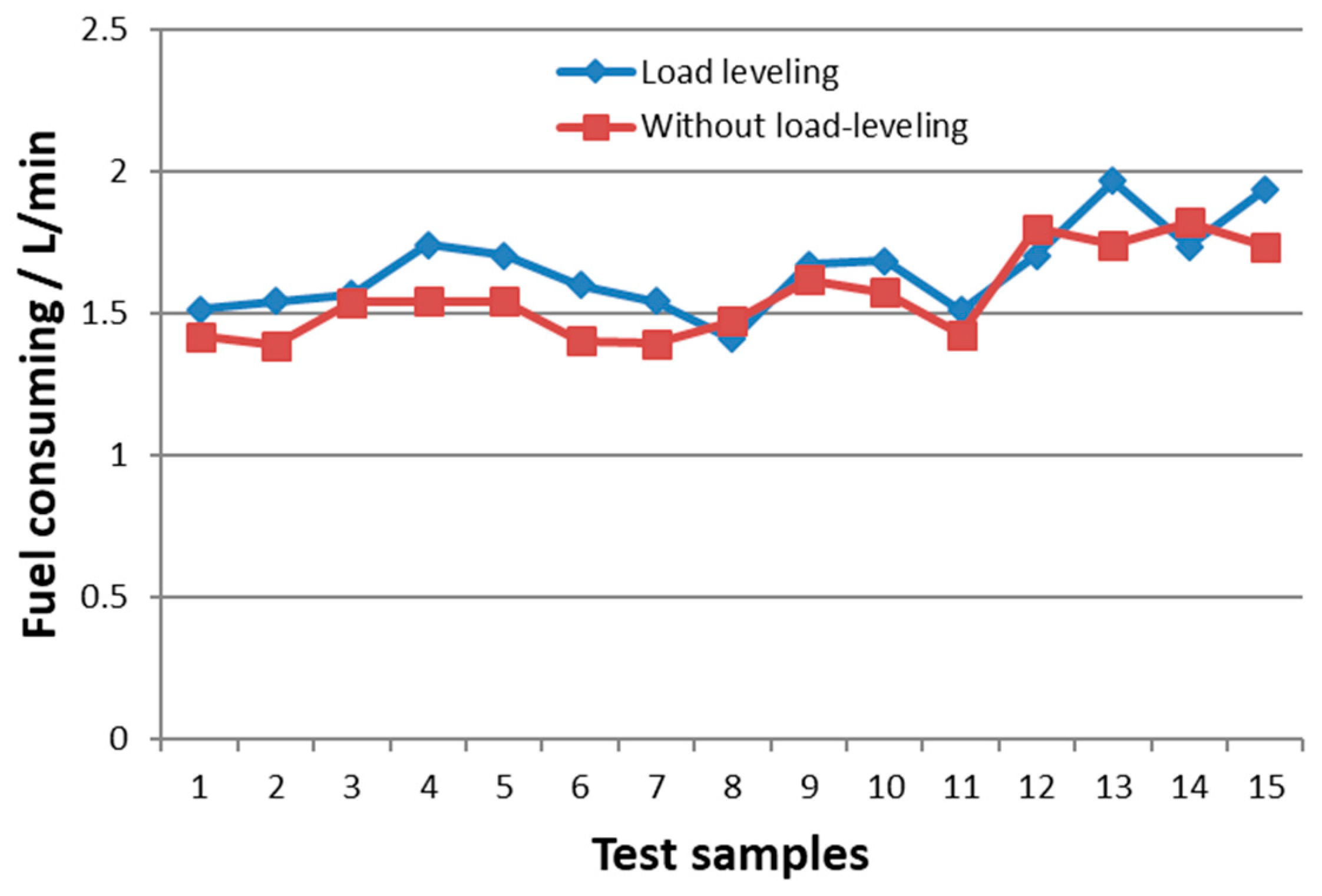
In the fuel consumption comparison test, the two modes in traditional power or in hybrid power run alternatively for the running in the hole. Ten drill strings (in three rods) were connected and lowering into the well in one fuel consumption test group.
Table 2 cited the fuel consumption data of 10 test groups. The results of the other 20 groups tested is also depicted in
Figure 19.
Table 2 and
Figure 19 indicates that the cost of the smooth running is more fuel consumption in 5–10%. The more fuel-consuming phenomenon was theoretically predicted in part 3.1 for the case of the single engine mode.
In order to save fuel, the load characters, the engines selection, the hybrid power configuration, and the load-leveling mode should be researched carefully. From the theoretical analysis in
Section 3.1 and
Section 3.2, it is estimated that the smaller diesel engine with power of 400 to 600 kW in load-leveling will consume less fuel than the 800 kW engine running in a traditional mode.
4.5. Fuel Saving Verification Test
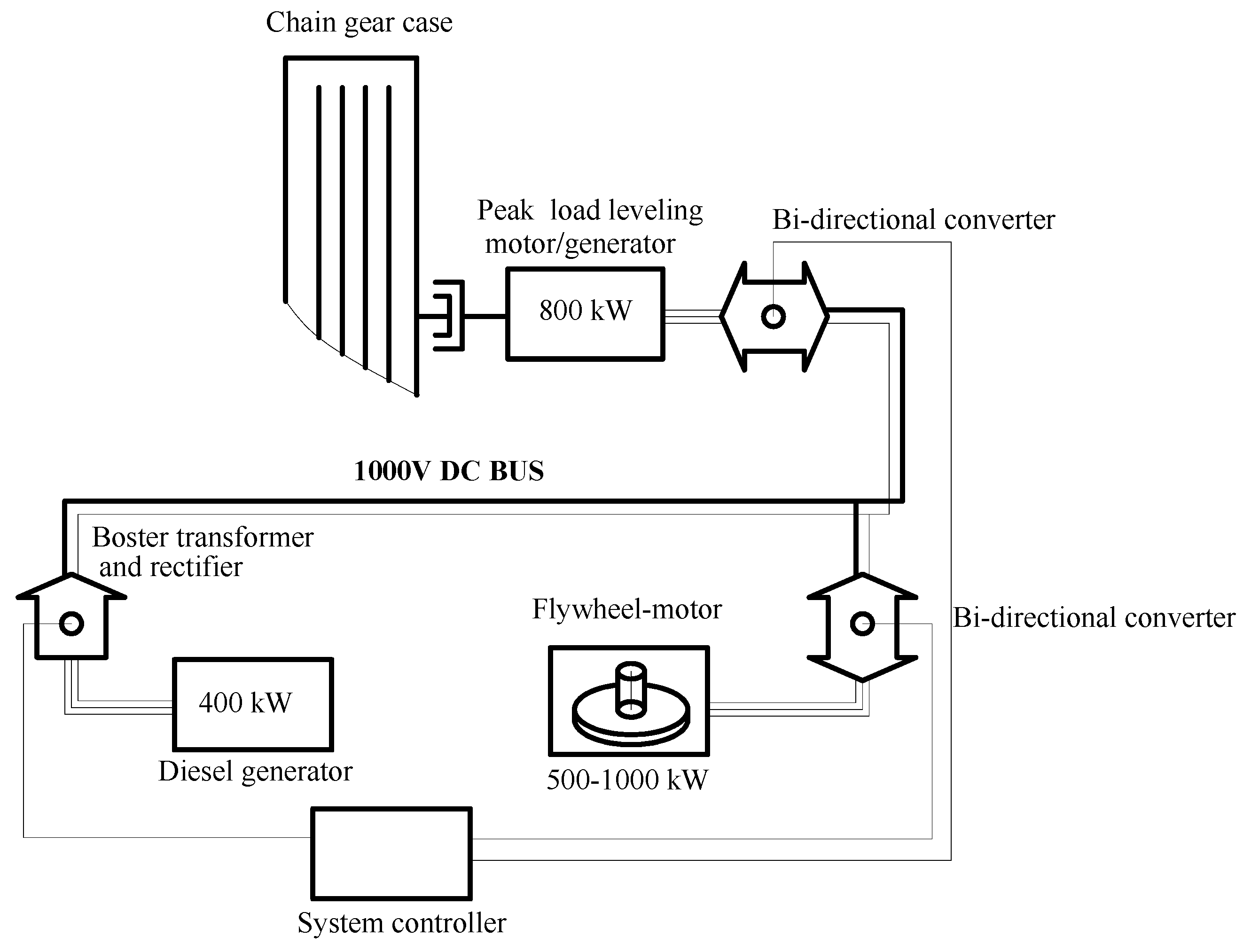
To check the possibility of fuel saving, a verification experiment was designed and carried out on another oil-drilling platform. In the smoothing running test in 4.4, the 400 kW loading leveling motor and 400 kW FESS seems to be smaller than the desired configuration for the engineering practice. Therefore, in the new verification project, the 800kW load leveling motor and 500–1000 kW/60 MJ FESS were developed. The 800 kW load leveling motor could work like the 800 kW diesel engine in short time with much better speed regulation being necessary to solve sticking of the drill tool.
The 400 kW diesel generator was configured in the drill machine for generating electricity when the 800 kW engines stopped in the main power system driving the chain transmission box. Smaller engine in smooth running with a load-leveling mode has the potential to save fuel from the above theoretical prediction. The configuration of the new hybrid power system is shown in
Figure 20. To use the 400 kW diesel generator as the only original power of the draw-works for lifting work through the load-leveling motor (with power of 800 kW) and the flywheel system (with power of 500 to 1000 kW and energy of 60 MJ), a step-up transformer and a rectifier was designed in our experiment study. Being the power source of the rectifier, the step-up transformer raised the voltage of AC 380 V generated by the 400 kW diesel generator to the AC 600 V. The rectifier in 300 kW generated the DC 1000 V power source for the flywheel energy storage. In this mode, the flywheel energy storage system works as an amplifier to bear the high impact load through the peak load leveling motor.
The lifting and lowering work in the load of 38 tons in the fuel consumption comparison experiments was repeated 50 times both in the load leveling mode and the traditional driving mode (one 800 kW diesel engine driving the chain box without load-leveling). A 21% fuel saving was obtained in the comparison test, as shown in
Table 3. The fuel saving is higher than the theoretical prediction because the load leveling motor drives the chain box in lower speed with less energy consumption than that of the 800 kW diesel engine running in higher speed.
5. Conclusions
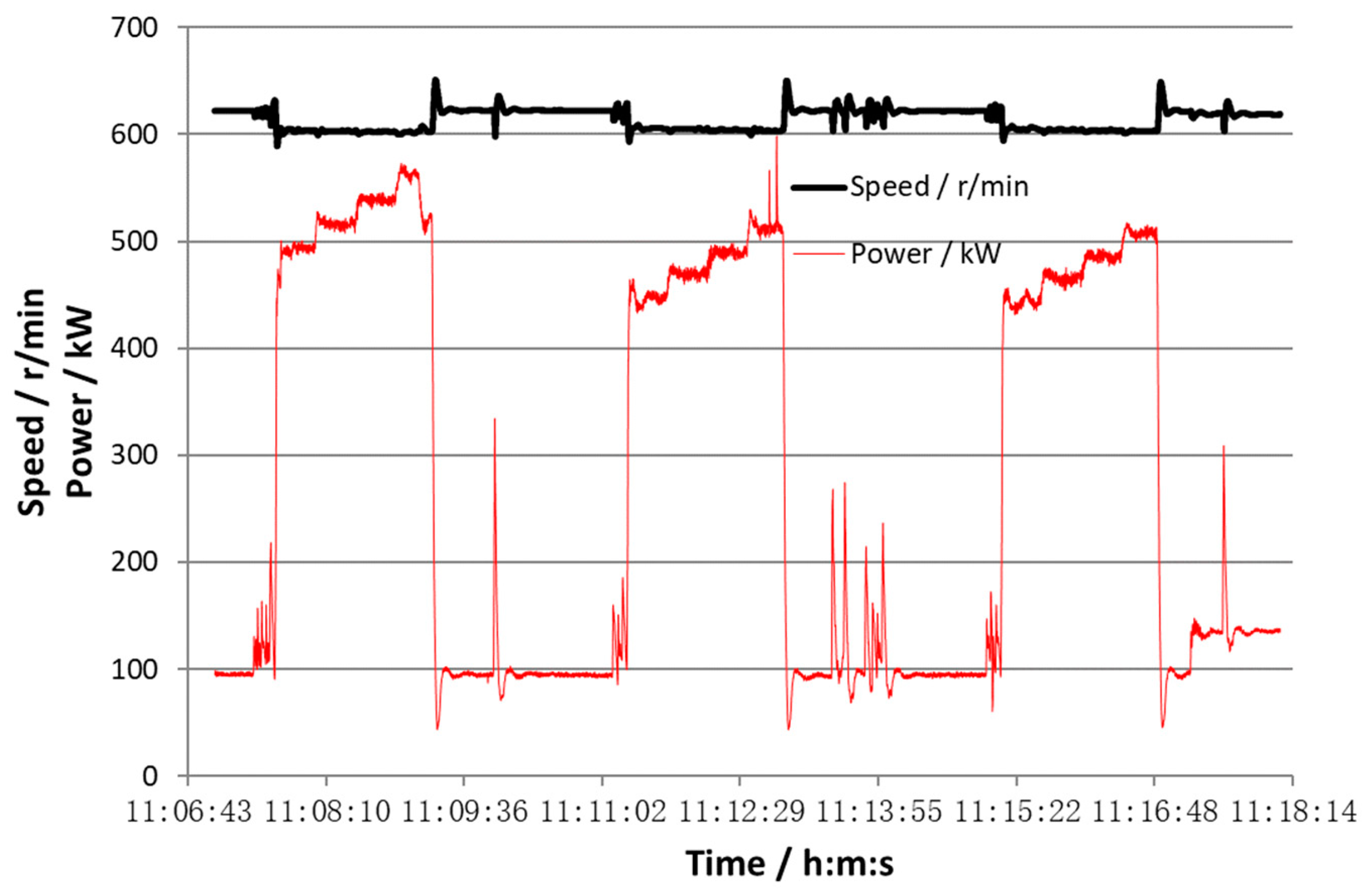
In our experimental case study, the peak load was 770 to 830 kW and the valley load was 200 to 250 kW when running in the hole. The peak load was 450 to 550 kW and the valley load was 100 to 150 kW for putting out of the hole. The diesel engine output varied in the cycle for 2 to 4 minutes.
The model of the hybrid power system with peak load leveling was built to get the fuel consumption in different load leveling running types. The theoretical results indicated that there should be 1%–13% more fuel consumed for the steady output of single engine in the load-leveling running mode. The fuel saving of 1%–12% is possible for the case of a single engine in the load-leveling running mode compared to Bi-engines in a traditional running mode when the peak load is 900–1200 kW and the valley load is 200–600 kW. There are many factors affecting the fuel consumption such as valley-peak time ratio, the oscillation power values, and the efficiency of peak load leveling. The smaller engine may be used for the peak load leveling running mode, which means greater fuel saving possibility.
The verification experiment of the peak load leveling with FES confirmed that the diesel engine worked more steadily with lower smoke emissions (due to incomplete combustion) in response to impact load with the cost of more fuel consumed. The quick drop of the engine in the impact load decreased by 50% and the peak output was about 80% in the case with a peak load leveling. In addition, 5% to 10% more fuel consumed in the load-leveling test compared to the traditional running mode with the driving of the 800 kW diesel engine. However, 21% fuel saving was obtained in the load-leveling test with the driving of the 400 kW diesel generator. Therefore, both the engine smooth running and fuel saving could be achieved in the hybrid power technology for the oil drilling rig.


