Article

Adaptive Sliding Mode Control for PMSG Wind Turbine Systems

Department of Electrical Engineering, Chungnam National University, Daejeon 34134, South Korea
*
Author to whom correspondence should be addressed.
Energies 2019, 12(4), 595; https://doi.org/10.3390/en12040595
Submission received: 30 November 2018 / Revised: 20 January 2019 / Accepted: 5 February 2019 / Published: 13 February 2019
(This article belongs to the Section F: Electrical Engineering)

Abstract

:
In this paper, variable speed PMSG wind turbine systems with unknown system parameters, such as vicious friction coefficient and total inertia, are considered. The errors and variations of wind speed are modeled as a disturbance in mechanical torque. In general, the optimum rotating speed is given based on the MPPT (Maximum Power Point Tracking) algorithm and the designed controller tracks the reference (optimum) rotating speed in spite of these parametric uncertainties and disturbances. In order to have a desired rotor speed, a sliding mode current controller is proposed to have robustly stabilizing torque input. From the robustly stabilizing q-axis current i q , q-axis voltage input u q is obtained. Additionally, the d-axis control input u d is designed to regulate the d-axis current i d . The adaptive estimator, for the total inertia J and the viscous friction coefficient F , is designed by a backstepping control technique. The robust stability of the closed-loop system is shown using a Lyapunov function. The proposed controller is verified via a simulation using MATLAB/Simulink.

1. Introduction

Wind turbines in wind power generation systems can be classified as inductive or synchronous depending on the rotor of the generator [1]. Initially, the wind power generation industry used doubly-fed induction generators, for which the operating speed of the generator can be controlled using a slip. However, permanent magnet synchronous generators are increasingly being adopted for scenarios requiring high generation capacity, easy maintenance management, and cost efficiency, such as offshore wind power generation complexes. Permanent magnet synchronous generators (PMSG) have the advantages of reduced production costs due to developments in processing technology, reduced operating noise due to the use of permanent magnets in the rotors, reduced generator weight, and reduced maintenance costs. They also have the advantage of being able to create high torque output compared to doubly-fed induction generators due to high magnetic flux density and efficiency [2,3,4,5,6,7].
Wind turbines can be designed to operate at fixed speed or at variable speed [2,8]. Fixed-speed operating systems transform wind energy into electrical energy using induction generators directly connected to a three-phase power grid. The rotor of the wind turbine is coupled to the generator shaft with a fixed ratio gearbox and operates at constant speed. By contrast, variable speed operating systems are systems which vary the rotation speed of the generator’s rotors, and they are mainly used in synchronous generators. Variable operating wind power generators do not connect directly with the grid, instead connecting with it through a converter, and the generator is operated through aerodynamic control to adjust the torque, speed, and power. This reduces the mechanical stress and aerodynamic noise, and the generator can be controlled such that the wind power turbine operates at the maximum output coefficient over a wider range of wind speeds [2,9].
Here, the control method for energy production at maximum efficiency is called maximum power point tracking (MPPT) [10]. An MPPT controller calculates the optimal rotor rotation speed for varying wind speeds. Therefore, the location and accuracy of the sensors which measure wind speed can be considered as important factors. To extract maximum power, linear controllers are designed based on an approximated linear model, such as conventional vector control with proportional-integral loops [3,9]. However, these control strategies may not provide satisfactory performances due to the system nonlinearity of the PMSG and wide-range operation points. To improve the performance, a feedback linearizing control based MPPT is proposed [11], where the mechanical rotation speed controller and current controllers are designed via linear control methods. However, this results in a complex control law and has weak robustness against parameter uncertainties and external disturbances. Generally, wind power turbine rotors have very large diameters, and wind speeds vary according to the location on the turbine from which wind speeds are measured, so wind speed measurements may not be a suitable value for maximum energy production, depending on the measurement location. Therefore, wind speed measurement is more suitable for systems with severe noise due to the environmental uncertainty caused by measurement location and by noise inherent in their sensors. Because wind power turbine systems have significant uncertainty in their mechanical elements, control techniques are required to overcome this problem.
Sliding mode control (SMC) has been frequently used as a robust control for disturbance and uncertainty among the various robust control methods. Some papers on the application of SMC to wind energy conversion system have been presented in recent decades [11,12,13,14,15,16,17,18,19,20,21,22]. In the early studies of [11,12], SMC is applied for MPPT in the wind energy conversion system with uncertainties. In [12], an optimal torque SMC strategy for a variable speed wind turbine system is proposed to implement MPPT tasks. In other words, SMC strategy was applied for controlling electromagnetic torque in MPPT for PMSG. In reference [11], an input-output linearization technique and SMC are applied to a wind energy conversion system with unstructured uncertainties. In [13], an SMC based on Enhanced Exponential Reaching Law was proposed and investigated on a grid-connected PMSG wind turbine system. In [14,15], SMC was used to improve robustness under various operating conditions such as parameter changes or load variation, and to reduce errors between desired command values and actual current for d- and q-axis currents. In [16], an induction generator (IG) speed drive was designed with the application of a sliding mode controller and a proposed artificial neural network controller. In [17], optimum torque and rotor speed were studied to be obtained by defining the appropriate sliding surface. In [18], an adaptive SMC was studied, first by designing an SMC for reducing the rotor speed error in PMSG, followed by a design for controller gain and mechanical torque estimation.
For uncertain nonlinear systems with known bounds, classical sliding mode control provides robustness. Recently, the adaptive SMC designs adapt the switching gain online without any predefined knowledge of the bound of uncertainty [23,24]. To avoid over-estimation of gain, super twisting controllers [25,26] and Time-Delayed controllers [27,28,29,30] are proposed. [31] tracked the control of a class of uncertain nonlinear systems where the upper bound of the system uncertainty has explicit dependency on the system states.
In this paper, an adaptive robust sliding mode controller is proposed for a wind turbine system with parametric uncertainties and external disturbance. In the real system, some parameters, such as, mechanical inertia, viscous friction, stator resistance, inductance, are affected by operating conditions and manufacturing tolerance managed within predefined bounds. To improve the robustness and remove the effect of the noise and uncertainty which exist in wind speed measurements, an adaptive sliding mode controller is proposed. The wind speed sensor error is translated to an external torque disturbance with amplitude bound. To reject the torque disturbance, an SMC is designed for the nominal plant using the q-axis current as a virtual input. Next, the real physical control inputs, q-axis voltage and d-axis voltage, are designed to track the designed q-axis current and to regulate the d-axis current, respectively. An adaptation law is designed based on back-stepping technique while accounting for unknown parameters of the wind turbine system. The proposed controller is a dynamic controller which is composed of an SMC controller and parameter adaptation. The rotation speed error of rotor exponentially converges to the reference speed in spite of the external disturbance and unknown parameters.
The remainder of this paper is organized as follows. Chapter 2 briefly describes the wind energy conversion system in wind power generation systems. Chapter 3 defines the problem of noise and uncertainty in controller design, and describes the design of a controller to resolve this problem. Chapter 4 verifies the controller through simulations using MATLAB/Simulink, and Chapter 5 concludes the paper.

2. Modeling of a Wind Energy Conversion System

The wind power generation system model is shown in Figure 1. It is a system that converts wind energy into mechanical energy, and creates electrical energy through a generator. This system can be broadly divided into two parts: the generator side and the electrical grid side. This study focuses on controlling the generator side.

2.1. Wind Turbine Modeling

The kinetic energy of wind and the power of the wind can be expressed by Equations (1) and (2),
E = 1 2 m v 2 = 1 2 ( ρ A v t ) v 2 = 1 2 ρ A v 3 t ,
P w = E t = 1 2 ρ A v 3 = 1 2 ρ ( π R b 2 ) v 3 = 1 2 ρ π R b 2 v 3 ,
where E is the wind’s kinetic energy, ρ is the air density, A is the area that the wind passes through, v is the velocity of the wind, t is the time, P w is the power of the wind which can potentially be used, and R b is the radius of the wind power turbine through which the wind passes. The power of the wind expressed in Equation (2) only shows the maximum potential power that the wind has. In actuality, only part of this potential power can be used as electricity via the wind power turbine. The ratio of the wind’s power and the mechanical power which can be generated by the turbine is the power coefficient C p . The maximum value of the output coefficient is 59.26%, which is referred to as Betz's limit; however, it actually exists in the range of approximately 25 to 45%, which can be expressed as follows [32,33]:
C p = P m P w ,
C p ( λ , β ) = c 1 ( c 2 1 λ i c 3 β c 4 ) e c 5 λ i , 1 λ i = 1 λ + 0.08 β 0.035 β 3 + 1 .
where P m is the output mechanical power, λ is the tip speed ratio, β is the blade pitch angle, c 1 = 0.5 , c 2 = 116 , c 3 = 0.4 , c 4 = 5 and c 5 = 21 . The wind power turbine mechanical energy that can be extracted from the wind can be expressed via Equations (2) and (3) as shown below:
P m = 1 2 ρ π R b 2 C p ( λ , β ) v 3 ,
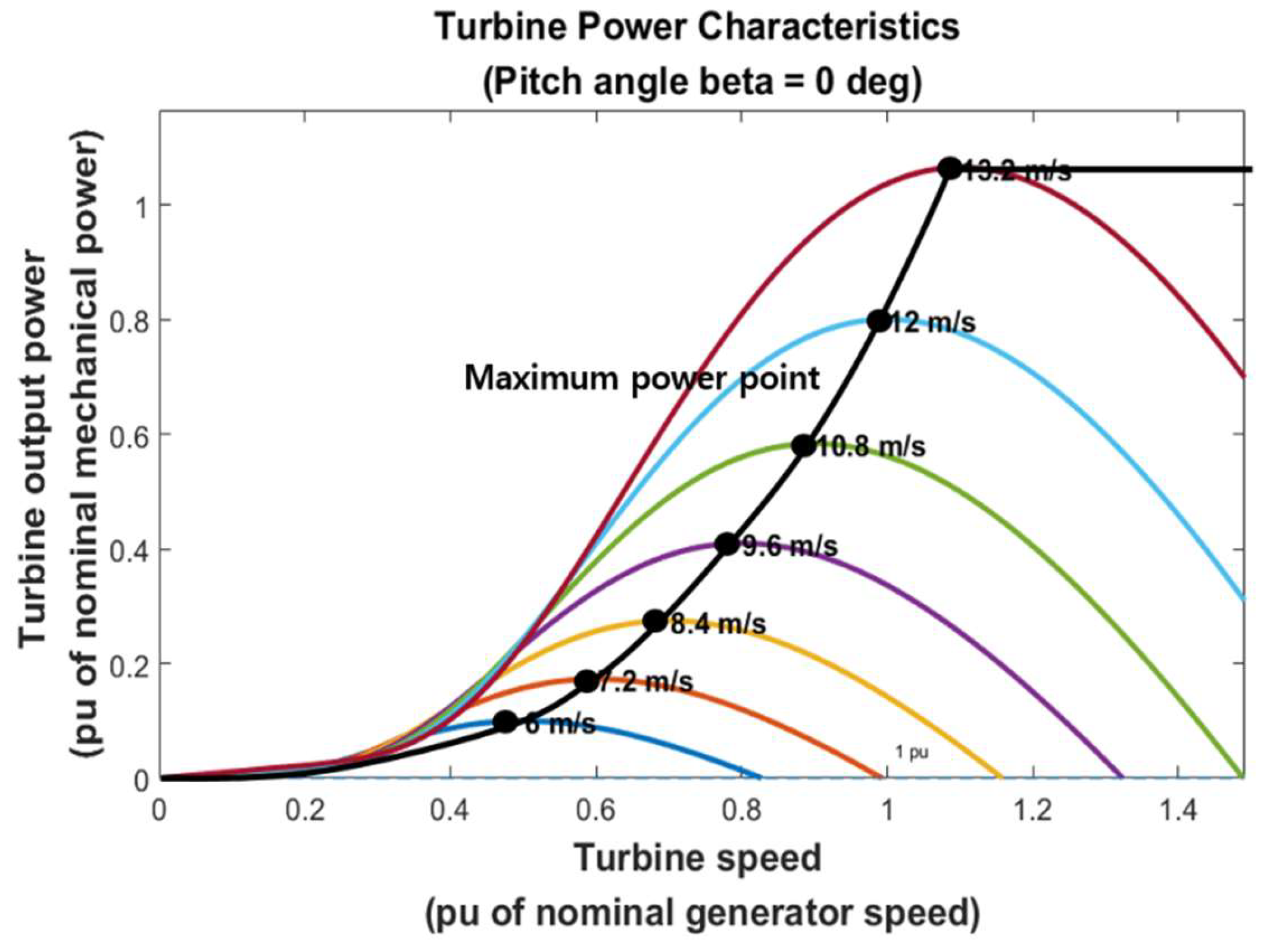
Output power according to the rotor rotation speed for each wind speed is shown in Figure 2.
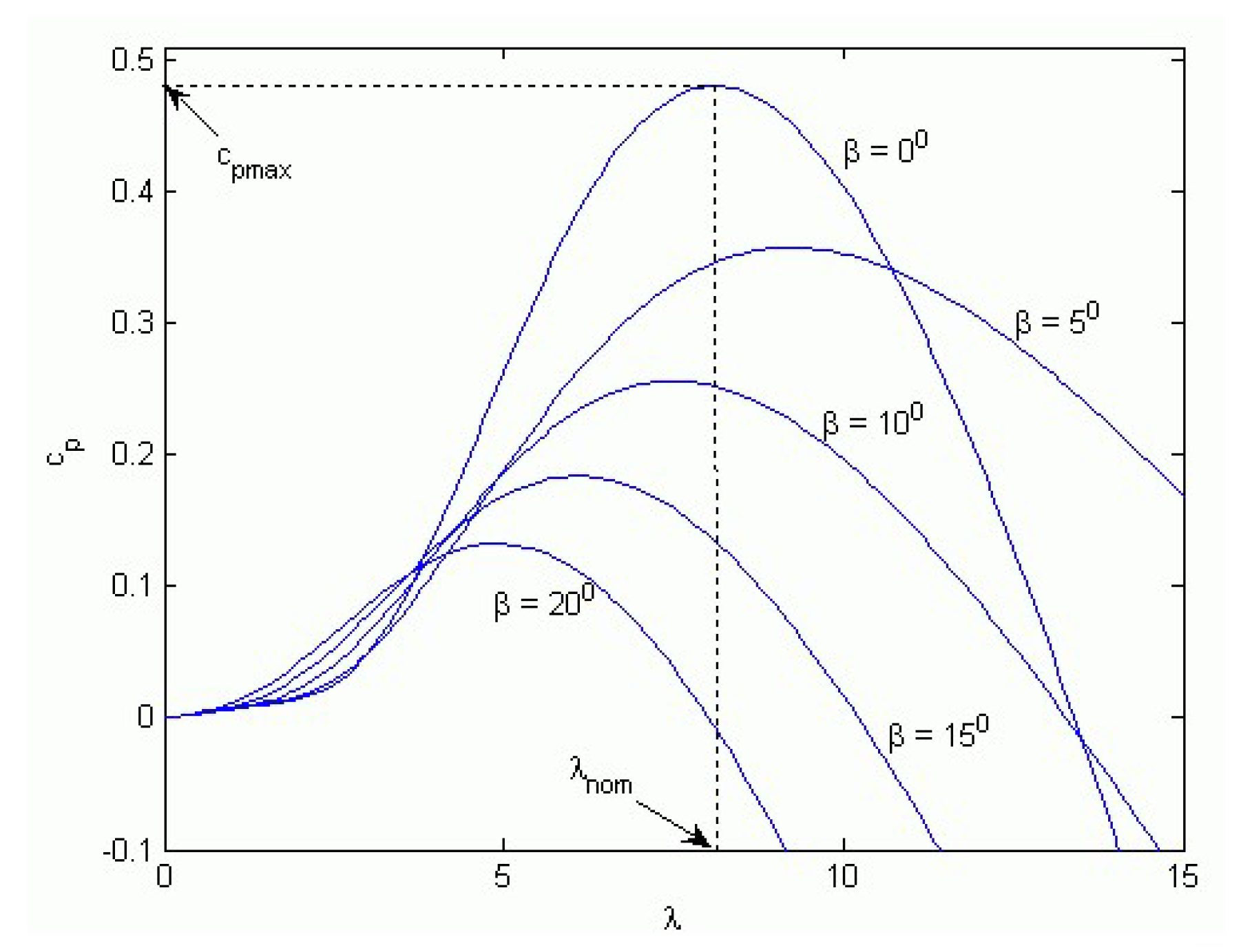
It can be seen that the maximum output energy in Figure 2 varies according to wind speed. The generator’s rotation speed at the maximum output energy is referred to as the optimal rotor speed ( ω o p t = ω r e f ), and the technique for maintaining this speed at each wind speed, obtaining maximum output energy, is MPPT (Maximum Power Point Tracking) [10,34]. According to the variation of β , typical characteristics of aerodynamic power coefficient correspond to tip speed ratio are illustrated in Figure 3. When β is maintained as a constant, we can see the power coefficient C p has only one maximum value C p max that corresponds to the optimal value of C p [34]. Therefore, C p max can be expressed as
C p o p t ( λ o p t , β ) = C p max , λ o p t = ω m o p t R b v ,
where λ o p t and ω m o p t are the optimal values of tip speed ratio and rotor speed, respectively. By choosing the optimal values of tip speed ratio for the maximum power coefficient, maximum power can be extracted from the optimal rotor speed.
The wind power turbine’s mechanical energy can be expressed as a product of the torque and rotation speed:
P m = T m ω m ,
where T m is the wind power turbine’s mechanical torque, and ω m is the wind power turbine rotor’s rotation speed. From Equations (5) and (7), the turbine’s torque is
T m = ρ π R 2 C p ( λ , β ) v 3 2 ω m .
The wind power generator’s basic dynamic equation is
T m = T e + F ω m + J d ω m d t ,
where F is the viscous friction coefficient, J is the total inertia, and T e is the electromagnetic torque.

2.2. PMSG Modeling

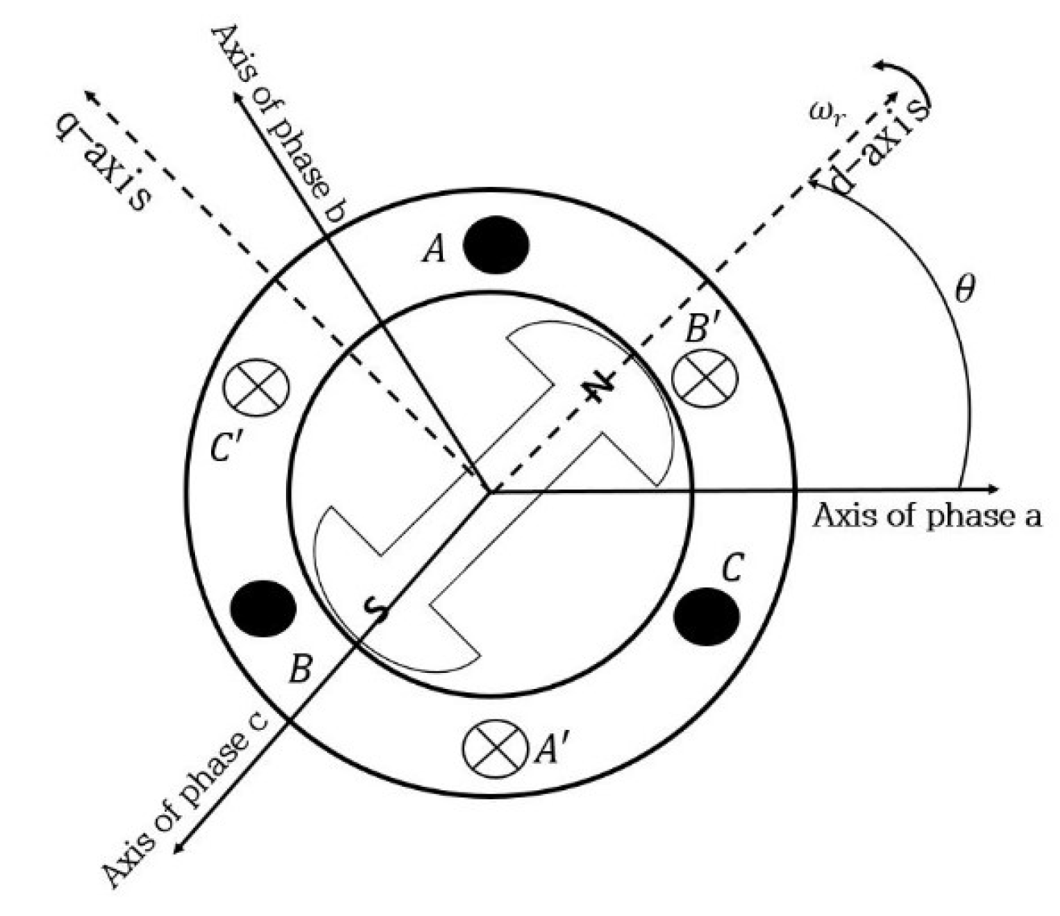
Normally, the currents and the voltages in 3-phase systems are represented in dq frame using dq transformation. In dq transformation, the d axis is set as the generator rotor’s N pole, and the q axis is perpendicular to the electrical angle, and according to the stator’s 3-phase current and the electrical elements in a synchronously rotating coordinate axis, are transformed as shown in Figure 4. The PMSG kinetic equation, having been dq transformed, is shown below [1,4,7,9]:
d i d d t = R L i d + P ω m i q + 1 L u d ,
d i q d t = R L i q P ω m i d + 1 L P ψ m ω m + 1 L u q ,
where i d is the d-axis current flowing to the stator, i q is the q-axis current flowing to the stator, u d is the input voltage for the stator’s d axis, u q is the input voltage for the stator’s q axis, ω m is the generator’s rotor speed, R is the resistance, L is the inductance, P is the number of pole pairs, and ψ m is the magnetic flux of the PMSG.
Then, the electromagnetic torque is
T e = 3 2 P ( ψ m i q + ( L d L q ) i q i d ) ,
where T e is the electromagnetic torque of the generator. If the inductance of each axis has the same value ( L = L d = L q ), then Equation (12) can be simplified as
T e = 1.5 P ψ m i q .
Substitute Equation (13) into Equation (9), then the dynamics of the wind turbine are represented as
d ω m d t = 1 J ( T m 1.5 P ψ m i q F ω m ) .
From Equations (10), (11), and (14), the whole model is
d ω m d t = 1 J 1.5 P ψ m i q F J ω m + 1 J ( T m + Δ T m ) , d i q d t = R L i q P ω m i d + 1 L P ψ m ω m + 1 L u q , d i d d t = R L i d + P ω m i q + 1 L u d .
In this model, the viscous friction coefficient F and the total inertia J are known a priori. However, in practical cases, the true values are not the same as the designed ones, because of production variation and changes according to time. Furthermore, the mechanical torque T m includes disturbances such as wind speed changes. In the steady state, the mechanical torque T m is obtained using wind speed v and rotating speed ω m from Equation (8). Thus, Δ T m represents the time varying signal with bounded amplitude, which is induced by the measurement error of v and the rotation speed error. For the stable and robust operation, we should consider the unknown parameters F and J in the controller design stage.

3. Controller Design

For the nominal turbine’s mechanical torque T m , we can obtain from the measured wind speed v and rotor rotation speed ω m given by MPPT algorithm. However, the measured wind speed has some errors due to sensor noise and may not represent the effective wind speed according to the measurement sensor’s location. When the torque input error is Δ T m , the actual mechanical torque input is expressed as the sum of the known nominal value T m and the disturbance Δ T m . Under these conditions, the controller should track the reference rotation speed ω m to generate the maximum power.
To have a robustly stabilizing controller, we find a reference current input to stabilize the speed error based on the sliding mode control technique. The obtained control is the reference signal of q-axis current i q to control the rotation speed. Since the q-axis current i q is not the control input, the q-axis voltage u q is designed to make i q track the reference signal. The other control input u q , the d-axis voltage, regulates the d-axis current i d . For the unknown parameters, a parameter estimator is designed based on backstepping.

3.1. Sliding Mode Controller Design for the Rotation Speed Error Regulation

A robust torque controller is designed based on the sliding mode control technique to overcome torque disturbances. In general, sliding mode controllers achieve excellent tracking performances and robustness against modeling uncertainty and disturbances. If we define the sliding surface S as a rotating speed error and the system satisfies stable sliding mode condition, then the rotating error slides on the sliding surface, i.e., rotating speed error remains 0. To make a system satisfy the condition of achieving a stable sliding mode, S S ˙ < 0 , where S is the sliding mode plane, and S ˙ is the time derivative of S [35,36,37,38].
If the uncertainties in the mechanical torque are taken into account, the wind turbine PMSG system is represented as
d ω m d t = 1 J 1.5 P ψ m i q F J ω m + 1 J ( T m + Δ T m ) .
Define the rotor’s rotation speed error (speed tracking error)
z 1 = ω m ω m * ,
where ω m * is the reference rotation speed which is obtained by MPPT algorithm based on the measured wind speed, which may include sensor noises and wind speed variation. To have a torque controller, take the time derivative of Equation (17)
z ˙ 1 = ω ˙ m ω ˙ m * , = 1 J 1.5 P ψ m i q F J ω m + 1 J ( T m + Δ T m ) ω ˙ m * , = 1 J u ( t ) F J ω m + 1 J ( T m + Δ T m ) ω ˙ m * .
For the simple notations, the quantity 1.5 P ψ m i q is defined as u τ ( t ) , which can be interpreted as torque control input to track the reference rotation speed ω m . To have a robustly stabilizing sliding mode controller, we define the sliding surface as the speed tracking error
S ( t ) = z 1 = ω ω m * .
Assumption 1.
For the mechanical torque disturbance Δ T m ( t ) , there exists a positive real number δ that satisfies Equation (20).
| Δ T m ( t ) | δ .
The Assumption 1 implies that the influence on the torque by wind speed variation, sensor noises, and model uncertainties is limited by a bounded magnitude. Given the practical environment, this assumption is reasonable and acceptable. Now, we propose a torque control input u τ ( t ) for a given δ ,
u τ ( t ) = F ω m + J ω ˙ m * T m γ sgn ( z 1 ) c 1 J z 1 ,
where c 1 > 0 , η > 0 , and γ = δ + η 2 .
Proposition 1.
Suppose that a system (18) satisfies assumption 1 for a positive real number δ . Then, the error system (18) is robustly exponentially stable by the feedback input u τ ( t ) given as (21).
Proof of Proposition 1.
Define a Lyapunov function candidate as
V 1 = 1 2 S 2 .
Take the time derivative and by Assumption 1, we have
V ˙ 1 = S S ˙ = z 1 z ˙ 1 , = z 1 ( 1 J u τ ( t ) F J ω m + 1 J ( T m + Δ T m ) ω ˙ m * ) , = z 1 ( 1 J ( F ω m + J ω ˙ m * T m γ sgn ( z 1 ) c 1 J z 1 ) F J ω m + 1 J ( T m + Δ T m ) ω ˙ m * ) , = z 1 ( c 1 z 1 + 1 J ( Δ T m γ sgn ( z 1 ) ) ) , c 1 z 1 2 η 2 | z 1 | .
Since V ˙ 0 , the rotation speed error z 1 converges to 0 exponentially as time goes to infinity.  □
As in the conventional SMC, if we choose u τ ( t ) = F ω m + J ω ˙ m * T m ( δ + η 2 ) sgn ( z 1 ) c 1 J z 1 for some positive constant α , then we can show that V ˙ 1 η V 1 1 2 and the control law u ( t ) drives the speed error z 1 to zero in finite time t r 2 α | z 1 ( 0 ) | .
Remark 1.
From Equation (21), we have the reference q-axis current i q * to control the torque of PMSG as in the following Equation.
i q * = 1 1.5 P ψ m ( F ω m + J ω ˙ m * T m γ sgn ( z 1 ) c 1 J z 1 ) .

3.2. Voltage Controller Design and Adaptative Estimation for Unknown Parameters

In practical cases, many parameters are different from the designed values or changes over time. In this subsection, we assume that the viscous friction coefficient F and the total inertia J in Equation (16) have unknown values due to manufacturing tolerance. If the coefficients F and J are substituted with estimated values, the torque control input Equation (20) is
u ^ τ ( t ) = F ^ ω m + J ^ ω ˙ m * T m γ sgn ( z 1 ) c 1 J ^ z 1 ,
where F ^ is the estimated viscous friction F , and J ^ is the estimated total inertia J .
Define the input error z 2 as
z 2 ( t ) = u τ ( t ) u ^ τ * ( t ) .
Substitute Equation (26) into Equation (18); we have
z ˙ 1 = ω ˙ m ω ˙ m * , = 1 J u τ ( t ) F J ω m + 1 J ( T m + Δ T m ) ω ˙ m * , = 1 J ( z 2 + u ^ τ ( t ) ) F J ω m + 1 J ( T m + Δ T m ) ω ˙ m * , = 1 J z 2 + 1 J ( F ^ ω m + J ^ ω ˙ m * T m γ sgn ( z 1 ) c 1 J ^ z 1 ) F J ω m + 1 J ( T m + Δ T m ) ω ˙ m * , = c 1 z 1 + 1 J ( z 2 + ( Δ T m γ sgn ( z 1 ) ) + J ˜ ( c 1 z 1 ω ˙ m * ) F ˜ ω m ) ,
where J ˜ = J J ^ , and F ˜ = F F ^ . Take derivative Equation (25),
d d t ( u ^ τ ( t ) ) = F ^ ˙ ω m + F ^ ω ˙ m + J ^ ˙ ω ˙ m * + J ^ ω ¨ m * 2 γ δ ( z 1 ) c 1 J ^ ˙ z 1 c 1 J ^ z ˙ 1 , = F ^ ˙ ω m + J ^ ˙ ω ˙ m * + J ^ ω ¨ m * + F ^ ω ˙ m * + ( F ^ J ^ ˙ + c 1 J ^ ) c 1 z 1 + ( F J c 1 ) z 2 + 1 J ( F ^ J ^ c 1 ) ( Δ T m γ sgn ( z 1 ) ) 2 γ δ ( z 1 ) + J ˜ J ( ( c 1 z 2 c 1 J ^ ( c 1 z 1 ω ˙ m * ) ) + F ^ ( c 1 z 1 ω ˙ m * ) ) + F ˜ J ( c 1 J ^ ω m ( z 2 + F ^ ω m ) ) .
From Equations (27) and (28), the time derivative of z 2 is
z ˙ 2 = u ˙ τ ( t ) u ^ ˙ τ ( t ) , = 1.5 P ψ m ( P ω m i d R L i q P ψ m L ω m + 1 L u q ) ( F ^ ˙ ω m + J ^ ˙ ω ˙ m * + J ^ ω ¨ m * + F ^ ω ˙ m * 2 γ δ ( z 1 ) ) ( ( F ^ J ^ ˙ + c 1 J ^ ) c 1 z 1 + ( F J c 1 ) z 2 + 1 J ( F ^ J ^ c 1 ) ( Δ T m γ sgn ( z 1 ) ) ) J ˜ J ( ( c 1 z 2 c 1 J ^ ( c 1 z 1 ω ˙ m * ) ) + F ^ ( c 1 z 1 ω ˙ m * ) ) F ˜ J ( c 1 J ^ ω m ( z 2 + F ^ ω m ) ) .
Remark 2.
In practical control systems, it is impossible to implement the signum function sgn ( · ) and a generalized function δ ( · ) . By replacing the signum function with sigmoid function tanh ( · ) , we obtain similar results. If we use a sigmoid function tanh ( · ) , the Dirac delta function δ ( · ) will not appear in u ^ ˙ τ ( t ) . However, because of this approximation, the states are absolutely bounded instead of displaying exponential convergence. Please refer to Appendix A.
Assumption 2.
The variation ranges for total inertia J and viscous friction coefficient F are known, i.e. J [ J min , J max ] and F [ F min , F max ] .
As observed in Equation (27) and (29), the error system contains control input voltage u q and time derivatives J ^ ˙ and F ^ ˙ . For some Lyapunov function, if we can make the time derivative of Lyapunov function be negative by choosing appropriate functions for u q , J ^ ˙ , and F ^ ˙ , then the error system is stable in the sense of Lyapunov. Additionally, since PMSG uses a permanent magnet, the d-axis current may be zero. Therefore, the -axis current is regulated by control input voltage u d . In other words, if d-axis current tracking error is z 3 such that z 3 = i d i d * then z 3 goes to zero as time goes to infinity.
Now we propose the d,q-axis control input voltage u d , u q , and the estimator of J ^ , F ^ as follows:
u q = L 1.5 P ψ m ( F ^ ˙ ω m J ^ ˙ ω ˙ m * J ^ ω ¨ m * + c 1 J ^ ˙ z 1 c 1 2 J ^ z 1 + 2 γ δ ( z 1 ) ) + L 1.5 P ψ m ( c 1 z 2 F ^ ( ω ˙ m * c 1 z 1 ) + 2 γ J min | F ^ J ^ c 1 | sgn ( z 2 ) + c 2 z 2 ) + P L ω m i d + R i q + P ψ m ω m ,
u d = R i d P L ω m i q c 3 z 3 ,
J ^ ˙ = c 1 z 2 2 + ( c 1 J ^ z 2 F ^ z 2 + z 1 ) ( c 1 z 1 ω ˙ m * ) ,
F ^ ˙ = z 2 ( c 1 J ^ ω m z 2 F ^ ω m ) z 1 ω m .
Proposition 2.
Suppose that Assumption 1 and Assumption 2 are satisfied. By the control inputs (30) and (31) and the parameter estimator (32) and (33), the tracking error states, z 1 , z 2 , z 3 exponentially decay to the origin and the estimated parameters J ^ , F ^ converge to some bounded values.
Proof of Proposition 2. Define a Lyapunov function candidate as
V 2 = 1 2 z 1 2 + 1 2 z 2 2 + 1 2 z 3 2 + 1 2 J J ˜ 2 + 1 2 J F ˜ 2 .
Equation (34) is differentiated as follows:
V ˙ 2 = z 1 z ˙ 1 + z 2 z ˙ 2 + z 3 z ˙ 3 J ˜ J J ^ ˙ F ˜ J F ^ ˙ , = z 1 ( c 1 z 1 + 1 J ( z 2 + ( Δ T m γ sgn ( z 1 ) ) + J ˜ ( c 1 z 1 ω ˙ m * ) F ˜ ω m ) ) + z 2 ( 1.5 P ψ m ( P ω m i d R L i q P ψ m L ω m + 1 L u q ) ( F ^ ˙ ω m + J ^ ˙ ω ˙ m * + J ^ ω ¨ m * + F ^ ω ˙ m * 2 γ δ ( z 1 ) ) ) + z 2 ( ( F ^ J ^ ˙ + c 1 J ^ ) c 1 z 1 ( F J c 1 ) z 2 1 J ( F ^ J ^ c 1 ) ( Δ T m γ sgn ( z 1 ) ) ) J ˜ J z 2 ( ( c 1 z 2 c 1 J ^ ( c 1 z 1 ω ˙ m * ) ) + F ^ ( c 1 z 1 ω ˙ m * ) ) F ˜ J z 2 ( c 1 J ^ ω m ( z 2 + F ^ ω m ) ) + z 3 ( R L i d + P ω m i q + 1 L u d ) J ˜ J J ^ ˙ F ˜ J F ^ ˙ .
By Assumption 1, we have
| Δ T m γ sgn ( z 1 ) | 2 γ .
Hence, V ˙ 2 can be written as:
V ˙ 2 z 1 ( c 1 z 1 + 1 J ( z 2 + ( Δ T m γ sgn ( z 1 ) ) + J ˜ ( c 1 z 1 ω ˙ m * ) F ˜ ω m ) ) + z 2 ( 1.5 P ψ m ( P ω m i d R L i q P ψ m L ω m + 1 L u q ) ( F ^ ˙ ω m + J ^ ˙ ω ˙ m * + J ^ ω ¨ m * + F ^ ω ˙ m * 2 γ δ ( z 1 ) ) ) + z 2 ( ( F ^ J ^ ˙ + c 1 J ^ ) c 1 z 1 ( F J c 1 ) z 2 + 2 γ J | F ^ J ^ c 1 | sgn ( z 2 ) ) + z 3 ( R L i d + P ω m i q + 1 L u d ) J ˜ J ( ( c 1 z 2 c 1 J ^ ( c 1 z 1 ω ˙ m * ) ) z 2 + F ^ ( c 1 z 1 ω ˙ m * ) z 2 + J ^ ˙ ) F ˜ J ( c 1 J ^ ω m z 2 ( z 2 + F ^ ω m ) z 2 + F ^ ˙ )
From Equations (30)–(33), Equation (37) is rewritten as
V ˙ 2 c 1 z 1 2 + 1 J z 1 z 2 + 1 J z 1 ( Δ T m γ sgn ( z 1 ) ) F J z 2 2 + 2 γ | F ^ J ^ c 1 | ( 1 J 1 J min ) sgn ( z 2 ) z 2 c 3 z 3 2 , 1 J ( γ | Δ T m | ) | z 1 | 2 γ | F ^ J ^ c 1 | ( 1 J min 1 J ) | z 2 | + 1 J z 1 z 2 c 1 z 1 2 F J z 2 2 c 2 z 2 2 c 3 z 3 2 .
By the Cauchy-Schwarz inequality,
V ˙ 2 1 J ( γ | Δ T m | ) | z 1 | 2 γ | F ^ J ^ c 1 | ( 1 J min 1 J ) | z 2 | ( c 1 1 J ) z 1 2 ( c 2 + F 1 J ) z 2 2 c 3 z 3 2 , ( c 1 1 J ) z 1 2 ( c 2 + F 1 J ) z 2 2 c 3 z 3 2 .
For c 1 , c 2 and c 3 such that c 1 > 1 J min , c 2 > max { 1 F max J min , 1 F min J min } , c 3 > 0 , V ˙ 2 0 .
Thus, the error states z 1 , z 2 and z 3 decay to zero exponentially. Furthermore, if the error state z = ( z 1 z 2 z 3 ) is zero, then J ^ ˙ and F ^ ˙ are also zero. By LaSalle’s Invariance Principle, we can say the estimator output J ^ , F ^ converges to some bounded point. □
Hence, it can be concluded that the proposed controller (30)–(33) of the model of the wind energy conversion system with uncertainties (10), (11) and (16) guarantees that the rotating speed converges to the reference rotating speed ω m * exponentially. However, the parameter estimation converges to some values which may not the true ones.

4. Simulation Results

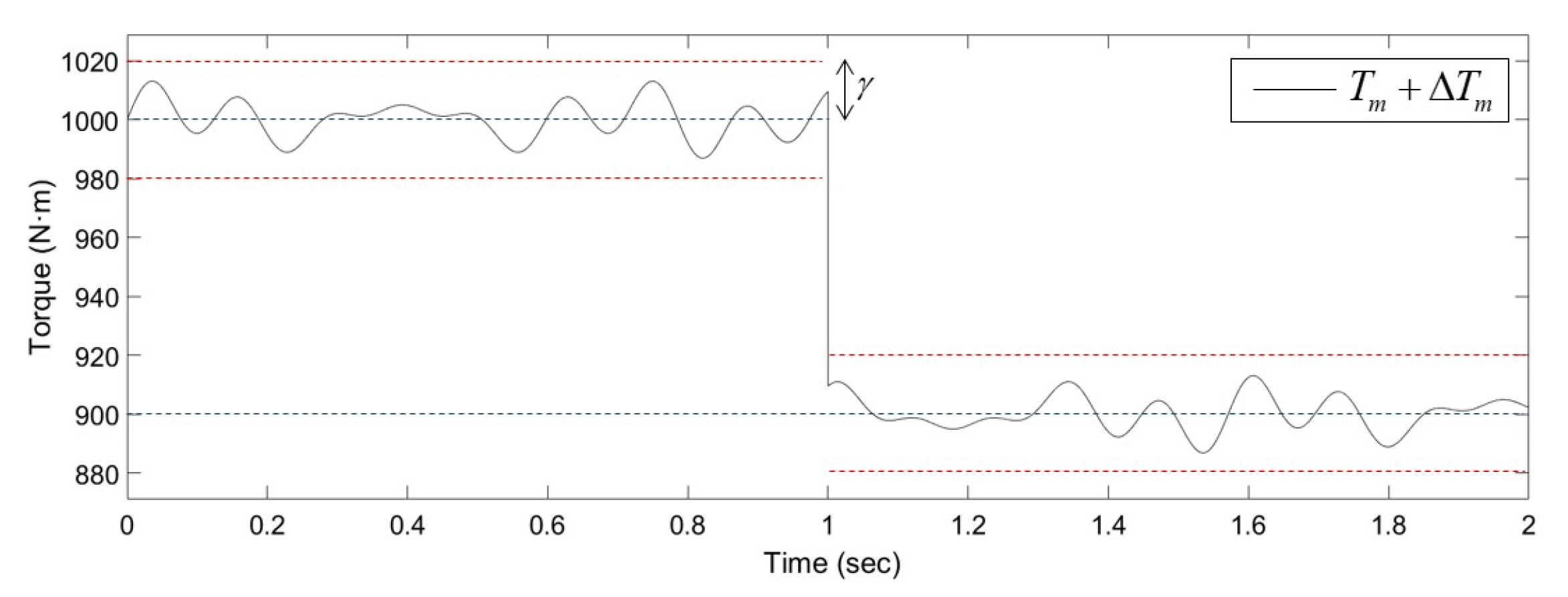
In order to verify the proposed adaptive sliding mode controller, a PMSG wind turbine system is simulated using MATLAB/Simulink, where the system parameters and the designed controller gains are presented in Table 1 and Table 2, respectively. The torque input used in the simulation is depicted in Figure 5, which starts at 1000 [ N m ] and drops to 900 [ N m ] at time t = 1 [ sec ] . The reference rotor speeds are 75[rad/s] and 70[rad/s] for each torque value. The sinusoidal input 5 sin ( 44 t ) + 5 sin ( 20 t ) + 5 sin ( 52 t ) is also applied as an external disturbance Δ T m which is bounded by δ = 17 . The initial values of the controller states F ^ and J ^ are assumed to be zero.
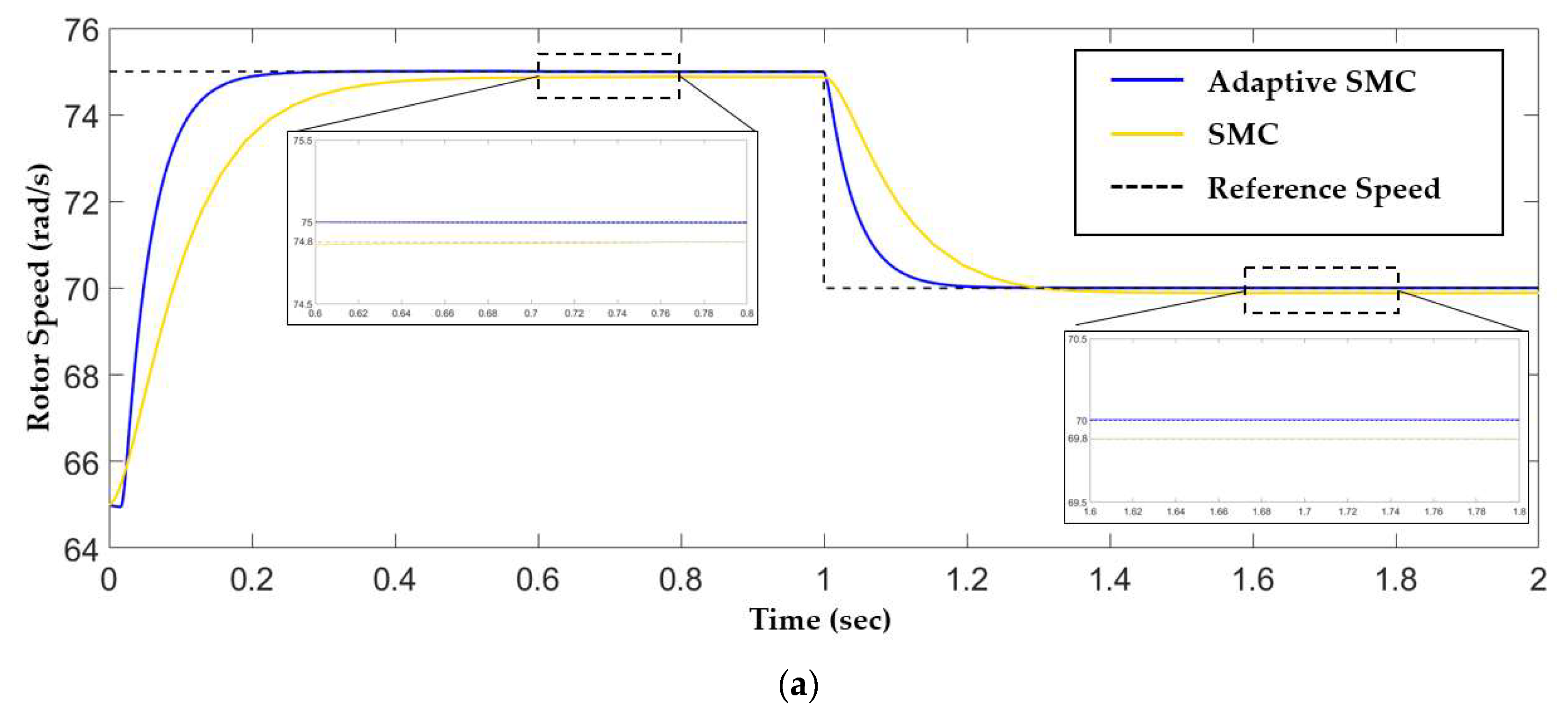
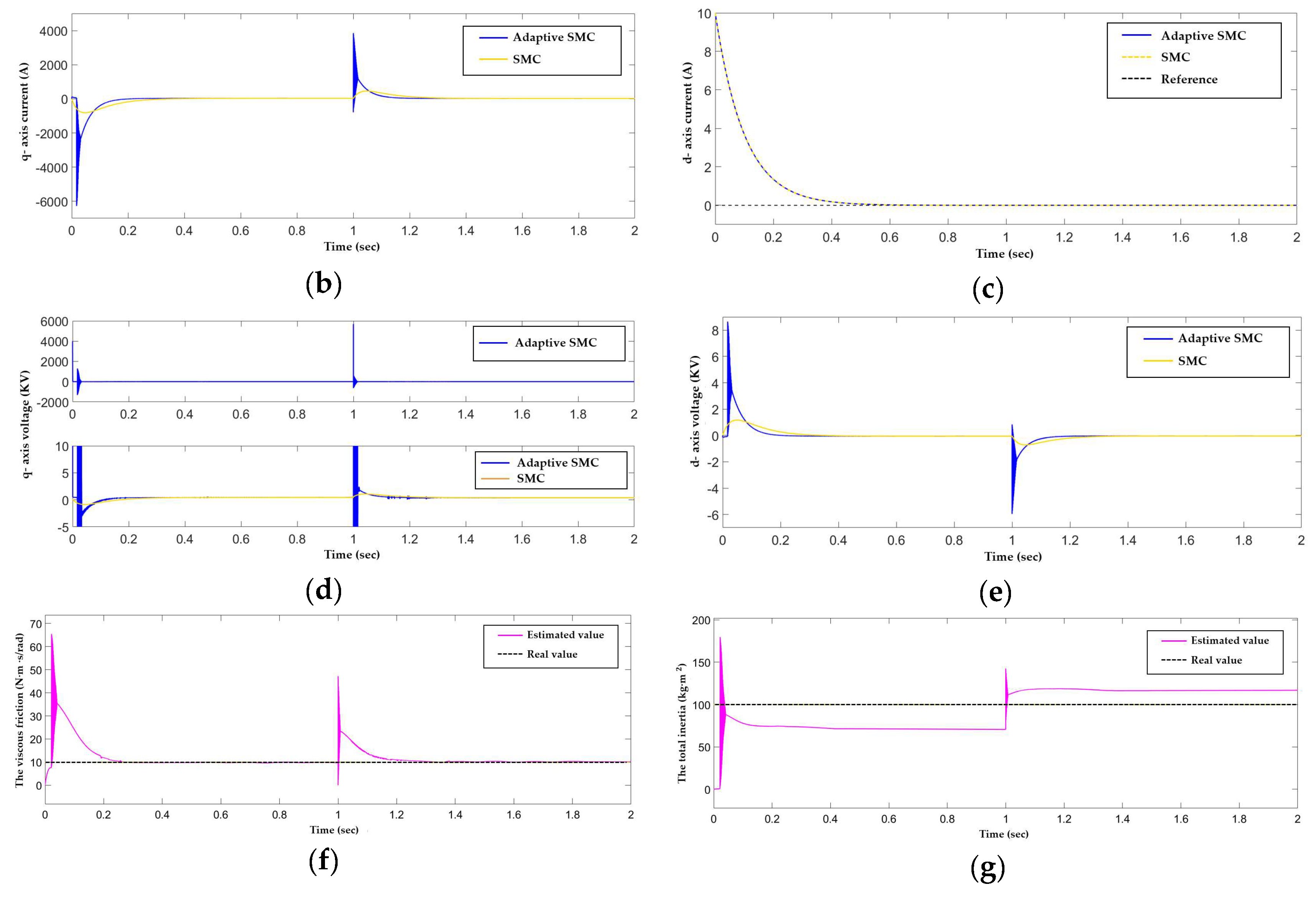
For the performance analysis, we use an SMC controller designed based on nominal values J n o m = 90 and F n o m = 9 without parameter adaption. As the simulation results, each of the system states and the estimated values are shown in Figure 6. In Figure 6a, the controller wind turbine rotor speeds ω m and the reference rotor speed ω m * are shown as a solid line and a dotted line, respectively. The reference rotor speed is initially 75[rad/s], and at time instant t = 1 [ sec ] , it changes to 70[rad/s]. In the presence of a torque disturbance and unknown parameters, the rotor rotating speed ω m exponentially converges to the reference speed ω m * in a short time using adaptive SMC. However, in the case of generic SMC, the rotor speed converged to 74.8[rad/s] and 69.8[rad/s] with remaining steady state error. The q- and d-axis currents i q , i d and reference values i q * , i d r e f are plotted in Figure 6b,c. The actual currents are solid lines, and the reference values are dotted lines. The q-, d-axis currents converge to the reference values in exponential way. The conversion rate is determined by choosing proper control parameters c 1 , c 2 , c 3 , as shown in the proof of Proposition 2. The control inputs q-axis voltage u q and d-axis voltage u d are depicted in Figure 6d,e. Due to the z 2 , chattering is observed during a reaching phase. The result of parameter estimator is shown in Figure 6d,e. As mentioned before, the estimated parameters converge to some bounded values which may different from the true ones.

5. Conclusions

An adaptive robust sliding mode controller is proposed for a PMSG wind turbine system which has parametric uncertainties and external torque disturbance. The torque disturbance includes the wind speed measurement error and mechanical vibrations, which influence the mechanical torque. The control purpose is to track the reference rotor speed which is given by the MPPT algorithm and to regulate the d-axis current. To obtain a robust controller, a q-axis current is used as virtual control input and q-axis voltage is designed for the q-axis current to track the designed virtual input using an adaptive SMC. Regarding the d-axis current, d-axis voltage is designed for d-axis current regulation. For the unknown parameters J and F, an adaptation law is designed to make the closed loop system be Lyapunov stable. The performance of the controller is verified through generator rotor speed tracking via a simulation using MATLAB/Simulink (R2017b, MathWorks). The error states converge to the origin exponentially, and estimated parameters converged to some bounded values. In addition, for a practical implementation sigmoid function, ultimate boundedness of error system is shown in Appendix A.
In the future, it will be necessary to extend to a complete wind power generation system including a grid side converter connected to a grid.

Author Contributions

Conceptualization, K-H.C.; Formal analysis, K-H.C.; Software, Sung-W.L.; Visualization, Sung-Won Lee; Writing – review & editing, K-H.C.

Funding

This research was funded by the Korea Electrical Power Corporation through the Korea Electrical Engineering and Science Research Institute, grant number R18XA06-56.

Conflicts of Interest

The authors declare no conflict of interest.

Appendix A

For the practical environments, all propositions are modified using sigmoid function tanh ( ) . The torque control input in Equation (21) is
u τ ( t ) = F ω m + J ω ˙ m * T m γ tanh ( z 1 ϕ ) c 1 J z 1 ,
where ϕ is the positive scalar to determine the boundary layer thickness.
Proposition A1.
Suppose that a system (18) satisfies assumption 1 for a positive real number δ . Then, the rotating speed error z 1 is ultimately bounded by the feedback input u ( t ) given as (A1).
Proof of Proposition A1.
Define a Lyapunov function candidate as
V 3 = 1 2 S 2 .
Take the time derivative; we have
V ˙ 3 = S S ˙ = z 1 z ˙ 1 , = z 1 ( 1 J u * ( t ) F J ω m + 1 J ( T m + Δ T m ) ω ˙ m * ) , = z 1 ( c 1 z 1 + 1 J ( Δ T m γ tanh ( z 1 ϕ ) ) ) , c 1 z 1 2 + 2 γ J | z 1 | .
Since V ˙ 3 0 for all z 1 , , | z 1 | 2 γ J c 1 , the solution z 1 is ultimately bounded. □
The control input Equation (25) is rewritten as the following equation:
u ^ τ ( t ) = F ^ ω m + J ^ ω ˙ m * T m γ tanh ( z 1 ) c 1 J ^ z 1
Substitute Equation (A4) into Equation (27), we have
z ˙ 1 = ω ˙ m ω ˙ m * , = 1 J z 2 + 1 J ( F ^ ω m + J ^ ω ˙ m * T m γ tanh ( z 1 ϕ ) c 1 J ^ z 1 ) F J ω m + 1 J ( T m + Δ T m ) ω ˙ m * , = c 1 z 1 + 1 J ( z 2 + ( Δ T m γ tanh ( z 1 ϕ ) ) + J ˜ ( c 1 z 1 ω ˙ m * ) F ˜ ω m ) .
Take derivative Equation (A4),
d d t ( u ^ τ ( t ) ) = F ^ ˙ ω m + F ^ ω ˙ m + J ^ ˙ ω ˙ m * + J ^ ω ¨ m * γ ϕ ( 1 tanh 2 ( z 1 ϕ ) ) z ˙ 1 c 1 J ^ ˙ z 1 c 1 J ^ z ˙ 1 , = F ^ ˙ ω m + J ^ ˙ ( ω ˙ m * c 1 z 1 ) + J ^ ω ¨ m * + c 1 2 J ^ z 1 c 1 z 2 + F J z 2 + F ^ ω ˙ m * F ^ c 1 z 1 γ ϕ ( 1 tanh 2 ( z 1 ϕ ) ) ( c 1 z 1 + 1 J z 2 + 1 J ( Δ T m γ tanh ( z 1 ϕ ) ) ) ( Δ T m γ tanh ( z 1 ϕ ) ) ( J ^ J c 1 F ^ J ) + F ˜ J ( c 1 J ^ ω m z 2 F ^ ω m + ω m γ ϕ ( 1 tanh 2 ( z 1 ϕ ) ) ) + J ˜ J ( c 1 z 2 c 1 J ^ ( c 1 z 1 ω ˙ m * ) + F ^ ( c 1 z 1 ω ˙ m * ) γ ϕ ( 1 tanh 2 ( z 1 ϕ ) ) ( c 1 z 1 ω ˙ m * ) )
From Equations (A5) and (A6), the time derivative of z 2 is
z ˙ 2 = u ˙ ( t ) u ^ ˙ τ ( t ) , = 1.5 P ψ m ( P ω m i d R L i q P ψ m L ω m + 1 L u q ) F ^ ˙ ω m J ^ ˙ ( ω ˙ m * c 1 z 1 ) J ^ ω ¨ m * F ^ ω ˙ m * + F ^ c 1 z 1 c 1 2 J ^ z 1 + c 1 z 2 F J z 2 + γ ϕ ( 1 tanh 2 ( z 1 ϕ ) ) ( c 1 z 1 + 1 J z 2 + 1 J ( Δ T m γ tanh ( z 1 ϕ ) ) ) + 1 J ( Δ T m γ tanh ( z 1 ϕ ) ) ( J ^ c 1 F ^ ) F ˜ J ( c 1 J ^ ω m z 2 F ^ ω m + ω m γ ϕ ( 1 tanh 2 ( z 1 ϕ ) ) ) J ˜ J ( c 1 z 2 c 1 J ^ ( c 1 z 1 ω ˙ m * ) + F ^ ( c 1 z 1 ω ˙ m * ) γ ϕ ( 1 tanh 2 ( z 1 ϕ ) ) ( c 1 z 1 ω ˙ m * ) ) .
Now we propose the d,q-axis control input voltage u d , u q , and the estimator of J ^ , F ^ as follows:
u q = L 1.5 P ψ m ( F ^ ˙ ω m J ^ ˙ ( ω ˙ m * c 1 z 1 ) J ^ ω ¨ m * c 1 2 J ^ z 1 + c 1 z 2 F ^ ω ˙ m * + F ^ c 1 z 1 γ ϕ ( 1 tanh 2 ( z 1 ϕ ) ) c 1 z 1 ) + L 1.5 P ψ m ( 2 γ J min | J ^ c 1 F ^ + γ ϕ ( 1 tanh 2 ( z 1 ϕ ) ) | tanh ( z 2 θ ) + c 2 z 2 ) + P L ω m i d + R i q + P ψ m ω m ,
u d = R i d P L ω m i q c 3 z 3 ,
J ^ ˙ = c 1 z 2 2 + c 1 J ^ z 2 ( c 1 z 1 ω ˙ m * ) F ^ z 2 ( c 1 z 1 ω ˙ m * ) + z 2 γ ϕ ( 1 tanh 2 ( z 1 ϕ ) ) ( c 1 z 1 ω ˙ m * ) + c 1 z 1 2 ω ˙ m * z 1 ,
F ^ ˙ = z 2 2 ( c 1 J ^ F ^ + γ ϕ ( 1 tanh 2 ( z 1 ϕ ) ) ) ω m z 2 z 1 ω m ,
where ϕ and θ are positive scalars to determine each boundary layer thickness.
Proposition A2.
Suppose that Assumption 1 and Assumption 2 are satisfied. By the control inputs (A8) and (A9) and the parameter estimator (A10) and (A11), the tracking error states, z 1 , z 2 , z 3 are ultimately bounded.
Proof of Proposition A2.
Define a Lyapunov function candidate as
V 4 = 1 2 z 1 2 + 1 2 z 2 2 + 1 2 z 3 2 + 1 2 J J ˜ 2 + 1 2 J F ˜ 2
Equation (A12) is differentiated as follows:
V ˙ 4 = z 1 z ˙ 1 + z 2 z ˙ 2 + z 3 z ˙ 3 J ˜ J J ^ ˙ F ˜ J F ^ ˙ , = z 1 ( c 1 z 1 + 1 J ( z 2 + ( Δ T m γ tanh ( z 1 ϕ ) ) + J ˜ ( c 1 z 1 ω ˙ m * ) F ˜ ω m ) ) + z 2 ( 1.5 P ψ m ( P ω m i d R L i q P ψ m L ω m + 1 L u q ) F ^ ˙ ω m J ^ ˙ ( ω ˙ m * c 1 z 1 ) ) + z 2 ( J ^ ω ¨ m * F ^ ω ˙ m * + F ^ c 1 z 1 c 1 2 J ^ z 1 + c 1 z 2 F J z 2 + γ J ϕ ( 1 tanh 2 ( z 1 ϕ ) ) z 2 ) + z 2 ( γ ϕ ( 1 tanh 2 ( z 1 ϕ ) ) ( c 1 z 1 + 1 J ( Δ T m γ tanh ( z 1 ϕ ) ) ) ) + z 2 1 J ( Δ T m γ tanh ( z 1 ϕ ) ) ( J ^ c 1 F ^ ) F ˜ J z 2 ( c 1 J ^ ω m z 2 F ^ ω m + ω m γ ϕ ( 1 tanh 2 ( z 1 ϕ ) ) ) J ˜ J z 2 ( c 1 z 2 c 1 J ^ ( c 1 z 1 ω ˙ m * ) + F ^ ( c 1 z 1 ω ˙ m * ) γ ϕ ( 1 tanh 2 ( z 1 ϕ ) ) ( c 1 z 1 ω ˙ m * ) ) + z 3 ( R L i d + P ω m i q + 1 L u d ) J ˜ J J ^ ˙ F ˜ J F ^ ˙ .
By using the Equation (36), V ˙ 4 can be written as:
V ˙ 4 c 1 z 1 2 + 1 J z 1 z 2 + 1 J ( Δ T m γ tanh ( z 1 ϕ ) ) z 1 + ( F J + γ J ϕ ( 1 tanh 2 ( z 1 ϕ ) ) ) z 2 2 + z 2 ( 1.5 P ψ m ( P ω m i d R L i q P ψ m L ω m + 1 L u q ) ) + z 2 ( F ^ ˙ ω m J ^ ˙ ( ω ˙ m * c 1 z 1 ) J ^ ω ¨ m * c 1 2 J ^ z 1 + c 1 z 2 F ^ ω ˙ m * + F ^ c 1 z 1 γ ϕ ( 1 tanh 2 ( z 1 ϕ ) ) c 1 z 1 ) + | z 2 | J 2 γ | γ ϕ ( 1 tanh 2 ( z 1 ϕ ) ) + J ^ c 1 F ^ | + z 3 ( R L i d + P ω m i q + 1 L u d ) F ˜ J ( c 1 J ^ ω m z 2 z 2 2 F ^ ω m z 2 + ω m z 2 γ ϕ ( 1 tanh 2 ( z 1 ϕ ) ) + z 1 ω m + F ^ ˙ ) J ˜ J ( c 1 z 2 2 c 1 J ^ z 2 ( c 1 z 1 ω ˙ m * ) + F ^ z 2 ( c 1 z 1 ω ˙ m * ) z 2 γ ϕ ( 1 tanh 2 ( z 1 ϕ ) ) ( c 1 z 1 ω ˙ m * ) c 1 z 1 2 + ω ˙ m * z 1 + J ^ ˙ )
From Equations (A8)–(A11), Equation (A14) is rewritten as:
V ˙ 4 1 J ( Δ T m γ tanh ( z 1 ϕ ) ) z 1 c 1 z 1 2 + 1 J z 1 z 2 + ( γ J ϕ ( 1 tanh 2 ( z 1 ϕ ) ) F J c 2 ) z 2 2 c 3 z 3 2 + 2 γ | γ ϕ ( 1 tanh 2 ( z 1 ϕ ) ) + J ^ c 1 F ^ | ( 1 J sgn ( z 2 ) 1 J min tanh ( z 2 θ ) ) z 2 , 1 J ( Δ T m γ tanh ( z 1 ϕ ) ) z 1 c 1 z 1 2 + 1 J z 1 z 2 + ( γ J ϕ F J c 2 ) z 2 2 c 3 z 3 2 + 2 γ | γ ϕ + J ^ c 1 F ^ | ( 1 J + 1 J min ) | z 2 | , 2 γ J | z 1 | + 2 γ | γ ϕ + J ^ c 1 F ^ | ( 1 J + 1 J min ) | z 2 | c 1 z 1 2 + 1 J z 1 z 2 + ( γ J ϕ F J c 2 ) z 2 2 c 3 z 3 2 .
By the Cauchy-Schwarz inequality,
V ˙ 4 ( c 1 1 J ) z 1 2 + 2 γ J | z 1 | ( c 2 1 J ( γ ϕ + F 1 ) ) z 2 2 + 2 γ | γ ϕ + J ^ c 1 F ^ | ( 1 J + 1 J min ) | z 2 | c 3 z 3 2 .
Let α 1 = c 1 1 J , β 1 = 2 γ J , α 2 = c 2 1 J ( γ ϕ + F 1 ) , β 2 = 2 γ | γ ϕ + J ^ c 1 F ^ | ( 1 J + 1 J min ) . Then we can rewrite Equation (A16) as
V ˙ 4 α 1 z 1 2 + β 1 | z 1 | α 2 z 2 2 + β 2 | z 2 | c 3 z 3 2 .
Therefore, the states are ultimately bounded. □

References

  1. Kundur, P. Power System Stability and Control; McGraw-Hill: New York, NY, USA, 1994. [Google Scholar]
  2. Chen, Z.; Guerrero, J.M.; Blaabjerg, F. A review of the state of the art of power electronics for wind turbines. IEEE Trans. Power Electron. 2009, 24, 1859–1875. [Google Scholar] [CrossRef]
  3. Li, S.; Haskew, T.A.; Swatloski, R.P.; Gathings, W. Optimal and direct-surrent vector control of direct-driven PMSG wind turbines. IEEE Trans. Power Electron. 2012, 27, 2325–2337. [Google Scholar] [CrossRef]
  4. Chinchilla, M.; Arnaltes, S.; Burgos, J.C. Control of permanent-magnet generators applied to variable-speed wind energy systems connected to the grid. IEEE Trans. Energy Convers. 2006, 21, 130–135. [Google Scholar] [CrossRef]
  5. Grauers, A. Efficiency of three wind energy generator systems. IEEE Trans. Energy Convers. 1996, 11, 650–657. [Google Scholar] [CrossRef] [Green Version]
  6. Chen, Y.; Pillay, P.; Khan, A. PM wind generator topologies. IEEE Trans. Ind. Appl. 2005, 41, 1619–1626. [Google Scholar] [CrossRef] [Green Version]
  7. Michalke, G.; Hansen, A.D.; Harkopf, T. Control strategy of a variable speed wind turbine with multipole permanent magnet synchronous generator. In Proceedings of the 2007 European Wind Energy Conference and Exhibition, Milan, Italy, 7–10 May 2007. [Google Scholar]
  8. Zavadil, R.; Miller, N.; Ellis, A.; Muljadi, E. Making connections: Wind generation challenges and progress. IEEE Power Energy. Mag. 2005, 3, 26–37. [Google Scholar] [CrossRef]
  9. Li, S.; Haskew, T.A.; Xu, L. Conventional and novel control designs for direct driven PMSG wind turbines. Electr. Power Syst. Res. 2010, 80, 328–338. [Google Scholar] [CrossRef]
  10. Abdullah, M.A.; Yatim, A.H.M.; Tan, C.W. A study of maximum power point tracking algorithms for wind energy system. In Proceedings of the IEEE First Conference on Clean Energy and Techonology (CET), Kuala Lumpur, Malaysia, 27–29 June 2011; pp. 321–326. [Google Scholar]
  11. Delfino, F.; Pampararo, F.; Procopio, R.; Rossi, M. A Feedback Linearization Control Scheme for the Integration of Wind Energy Conversion Systems into Distribution Grids. IEEE Syst. J. 2012, 6, 85–93. [Google Scholar] [CrossRef]
  12. Mao, J.; Wu, A.; Wu, G.; Zhang, X. Maximum power point tracking in variable speed wind turbine system via optimal torque sliding mode control strategy. In Proceedings of the 34th Chinese Control Conference (CCC), Hangzhou, China, 28–30 July 2015; pp. 7967–7971. [Google Scholar]
  13. Mozayan, S.M.; Saad, M.; Vahedi, H.; Fortin-Blanchette, H.; Soltani, M. Sliding mode control of PMSG wind turbine based on enhanced exponential reaching law. IEEE Trans. Ind. Electron. 2016, 63, 6148–6159. [Google Scholar] [CrossRef]
  14. Merzoug, M.S.; Banalla, H.; Louze, L. Sliding mode control (SMC) of permanent magnet synchronous generators (PMSG). Energy Procedia 2012, 18, 43–52. [Google Scholar] [CrossRef]
  15. Ciampichetti, S.; Corradini, M.L.; lppoliti, G. Sliding Mode Control of Permanent Magnet Synchronous Generator for Wind Turbines. In Proceedings of the 37th Annual Conference on IEEE Industrial Electronics Society, Melbourne, Australia, 7–10 November 2011; pp. 740–745. [Google Scholar]
  16. Hong, C.-M.; Huang, C.-H.; Cheng, F.-S.; Chih-Ming, H.; Cong-Hui, H.; Fu-Sheng, C. Sliding mode control for variable-speed wind turbine generation system using artificial neural network. Energy Procedia 2014, 61, 1626–1629. [Google Scholar] [CrossRef]
  17. Beltran, B.; Ahmed-Ali, T.; El Hachemi Benbouzid, M. Sliding mode power control of variable-speed wind energy conversion systems. IEEE Trans. Energy Convers. 2008, 23, 551–558. [Google Scholar] [CrossRef]
  18. Merabet, A.; Beguenane, R.; Thongam, J.S.; Hussein, I. Adaptive Sliding Mode Speed Control for Wind Turbine Systems. In Proceedings of the on 37th annual conference on IEEE Industrial Electronics Society, Melbourne, Australia, 7–10 November 2011; pp. 2461–2466. [Google Scholar]
  19. Sungwon, L.; Kwanho, C. Adaptive sliding mode controller design for MPPT control in wind turbine PMS generator with torque uncertainties and unknown parameter. J. Inst. Control Robot. Syst. 2018, 24, 532–539. [Google Scholar]
  20. Barambones, O. Sliding mode control strategy for wind turbine power maximization. Energies 2012, 5, 2310–2330. [Google Scholar] [CrossRef]
  21. El Magri, A.; Giri, F.; El Fadili, A.; Dugard, L. Adaptive nonlinear control of wind energy conversion system with PMS generator. In Proceedings of the 11th IFAC International Workshop on Adaptation and Learning in Control and Signal Processing, Caen, France, 3–5 July 2013; pp. 318–325. [Google Scholar]
  22. Tohidi, A.; Hajieghrary, H.; Hsieh, M.A. Adaptive disturbance rejection control scheme for DFIG-based wind turbine: Theory and experiments. IEEE Trans. Ind. Appl. 2016, 52, 2006–2015. [Google Scholar] [CrossRef]
  23. Plestan, F.; Shtessel, Y.; Bregeault, V.; Poznyak, A. New methodologies for adaptive sliding mode control. Int. J. Control 2010, 83, 1907–1919. [Google Scholar] [CrossRef] [Green Version]
  24. Plestan, F.; Shtessel, Y.; Bregeault, V.; Poznyak, A. Sliding mode control with gain adaptation—Application to an electropneumatic actuator. Control Eng. Pract. 2013, 21, 679–688. [Google Scholar] [CrossRef]
  25. Utkin, V.I.; Poznyak, A.S. Adaptive sliding mode control with application to super-twist algorithm: Equivalent control method. Automatica 2013, 49, 39–47. [Google Scholar] [CrossRef]
  26. Moreno, J.A.; Negrete, D.Y.; Torres-González, V.; Fridman, L. Adaptive continuous twisting algorithm. Int. J. Control 2016, 89, 1798–1806. [Google Scholar] [CrossRef]
  27. Roy, S.; Kar, I.N. Adaptive robust control of uncertain Euler-Lagrange systems with past data: A time-delayed approach. In Proceedings of the 2016 IEEE International Conference on Robotics and Automation (ICRA), Stockholm, Sweden, 16–21 May 2016; pp. 5715–5720. [Google Scholar]
  28. Roy, S.; Kar, I.N. Adaptive sliding mode control of a class of nonlinear systems with artificial delay. J. Frankl. Inst. 2017, 345, 8156–8179. [Google Scholar] [CrossRef]
  29. Roy, S.; Kar, I.N.; Jinoh, L.; Tsagarakis, N.G.; Caldwell, D.G. Adaptive-robust control of a class of EL systems with parametric variations using artificially delayed input and position feedback. IEEE Trans. Control Syst. Technol. 2017, 1–13. [Google Scholar] [CrossRef]
  30. Roy, S.; Kar, I.N.; Jinoh, L.; Maolin, J. Adaptive-Robust Time-Delay Control for a Class of Uncertain Eular-Lagrange Systems. IEEE Trnas. Ind. Electron. 2017, 64, 7109–7119. [Google Scholar] [CrossRef]
  31. Roy, S.; Roy, S.B.; Kar, I.N. A new design methodology of adaptive sliding mode control for a class of nonlinear systems with state dependent uncertainty bound. In Proceedings of the 15th International Workshop on Variable Structure Systems (VSS), Graz, Austria, 9–11 July 2018; pp. 414–419. [Google Scholar]
  32. Hau, E. Wind Turbines—Fundamentals, Technologies, Application and Economics, 2nd ed.; Springer: Berlin/Heidelberg, Germany, 2006. [Google Scholar]
  33. Heier, S. Grid Integration of Wind Energy: Onshore and Offshore Conversion Systems; John Wiley & Sons: Hoboken, NJ, USA, 2014. [Google Scholar]
  34. Abdullah, M.A.; Yatim, A.H.M.; Tan, C.W.; Saidur, R. A review of maximum power point tracking algorithms for wind energy systems. Renew. Sustain. Energy Rev. 2012, 16, 3220–3227. [Google Scholar] [CrossRef]
  35. Khalil, H.K. Nonlinear Systems, 3rd ed.; Prentice Hall: Upper Saddle River, NJ, USA, 2002. [Google Scholar]
  36. Perruquetti, W.; Barbot, J.P. Sliding Mode Control in Engineering; CRC Press: Boca Raton, FL, USA, 2002. [Google Scholar]
  37. Utkin, V.; Guldner, J.; Jingxin, S. Sliding Mode Control in Electro-Mechanical Systems; CRC Press: Boca Raton, FL, USA, 2009; pp. 325–355. [Google Scholar]
  38. Krstic, M.; Kanelakopoulos, I.; Kokotovic, P. Nonlinear and Adaptive Control Design; Wiley: New York, NY, USA, 1995. [Google Scholar]
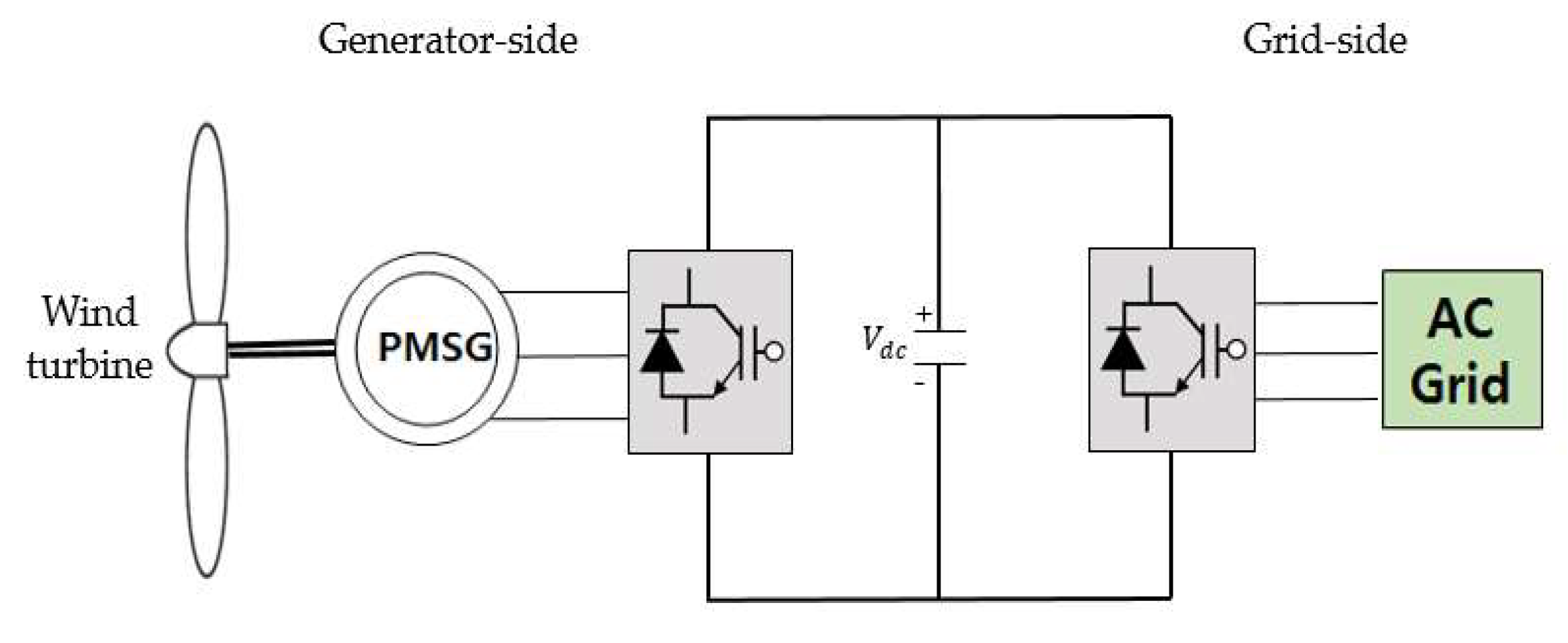
Figure 1. Wind Energy Conversion System.
Energies 12 00595 g001
Figure 2. Maximum Power Point Tracking with variable wind speeds.
Energies 12 00595 g002
Figure 3. Characteristics of Power coefficient versus Tip speed ratio for different blade pitch angles.
Energies 12 00595 g003
Figure 4. Schematic diagram of the Permanent Magnet Synchronous Generator.
Energies 12 00595 g004
Figure 5. The mechanical torque with external disturbance.
Energies 12 00595 g005
Figure 6. The Simulation results of the proposed adaptive SMC and SMC: (a) The rotor speed ω m and the reference rotor speed ω m * ; (b) The q-axis current i q and reference value i q * ; (c) The d-axis current i d and reference value i d r e f ; (d) The q-axis voltage input u q ; (e) The d-axis voltage input u d and reference value i d r e f ; (f) The real value of the total inertia J and estimator J ^ ; (g) The real value of the viscous friction coefficient F and estimator F ^ .
Energies 12 00595 g006aEnergies 12 00595 g006b
Table 1. The parameters of the wind turbine and the PMSG.
ParameterValueUnit
The resistance of the PMSG ( R ) 0.15 Ω
The inductance of the PMSG ( L ) 5.3 m H
The magnetic flux of the PMSG ( ψ m ) 1.314 w b
The number of pole pairs ( P ) 4-
The total inertia ( J ) 100 k g m 2
The minimum of inertia ( J min ) 80 k g m 2
The viscous friction coefficient ( F ) 10 N m s / r a d
The upper bound of disturbance ( δ )17-
Table 2. The control parameters.
ParameterValue
γ 20
c 1 20
c 2 20
c 3 10