Analysis of the Flow Field from Connection Cones to Monolith Reactors


Abstract
1. Introduction
2. Experiment Procedure
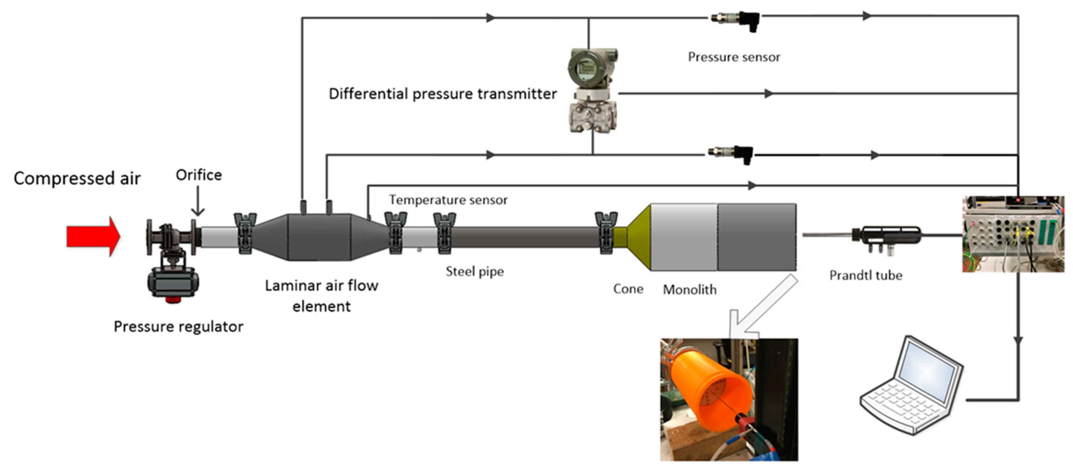
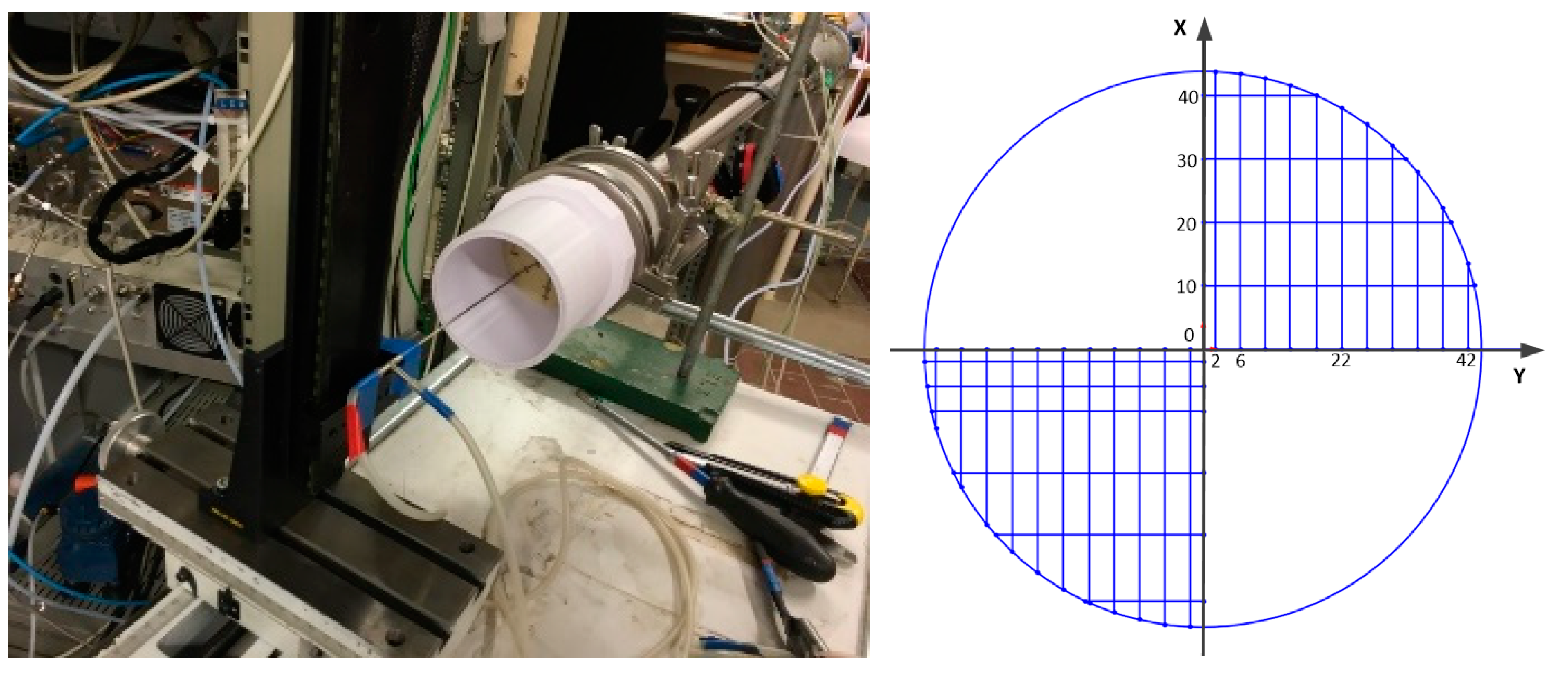
2.1. Experimental Equipment
2.2. Velocity Measurements
3. Model Formulation
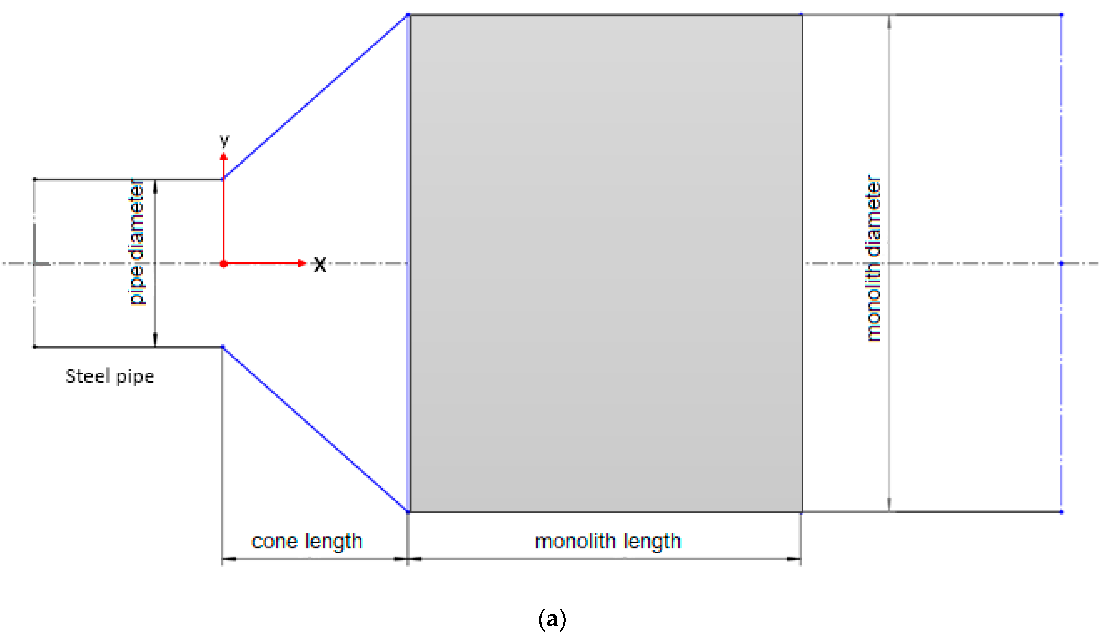
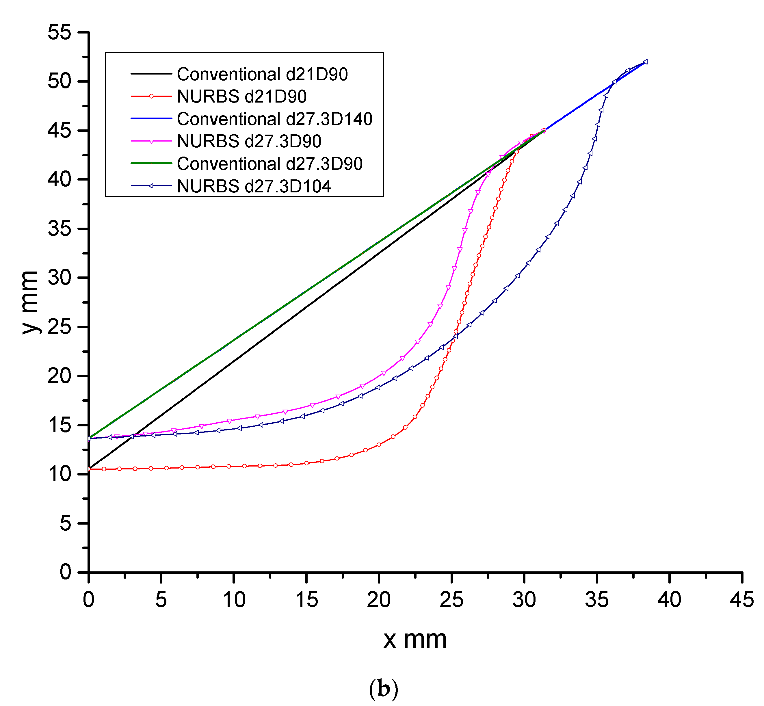
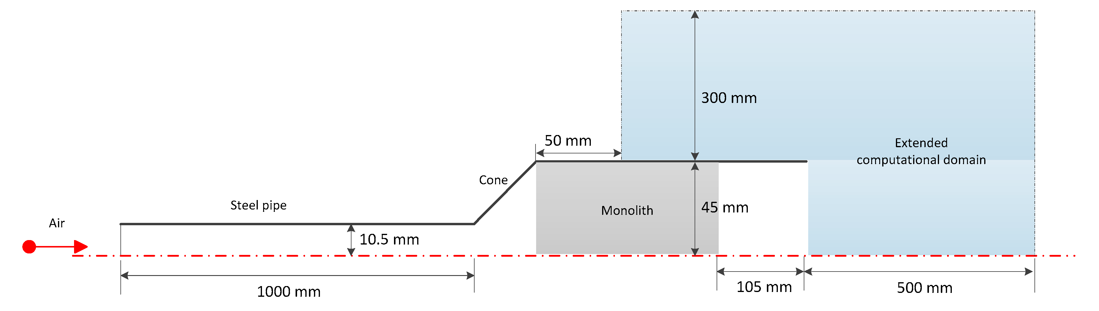
3.1. Modeling of the Open Section
3.2. Modeling of the Monolith
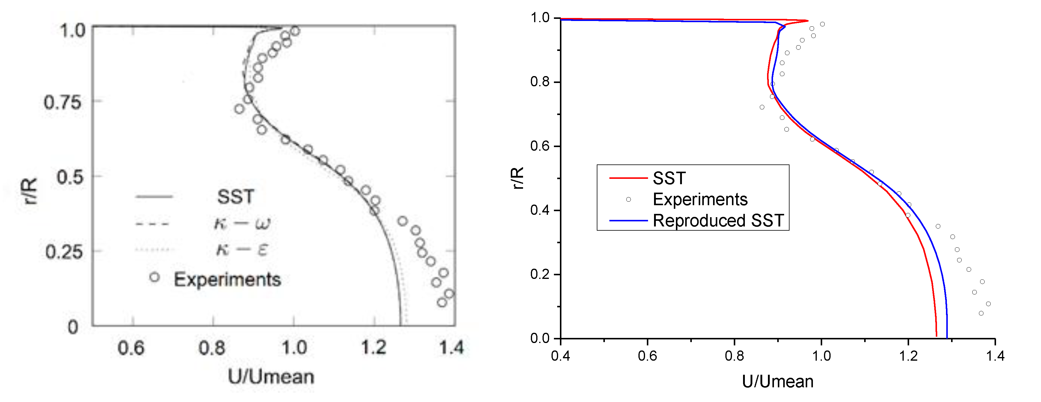
3.3. Grid Refinement and Validation
4. Results and Discussion
4.1. Pressure Drop
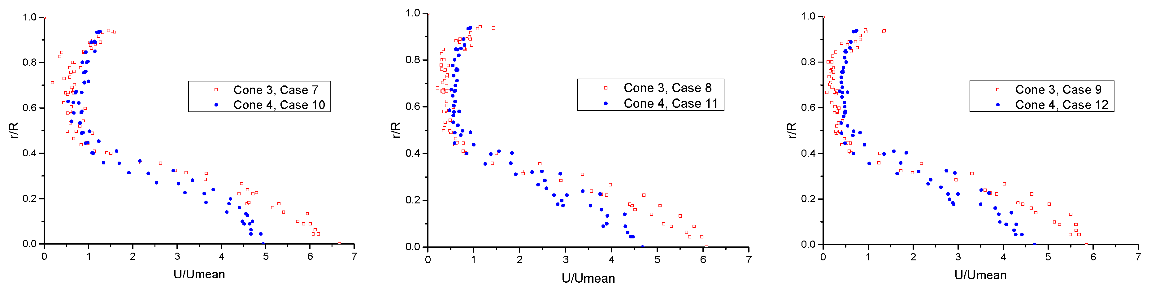
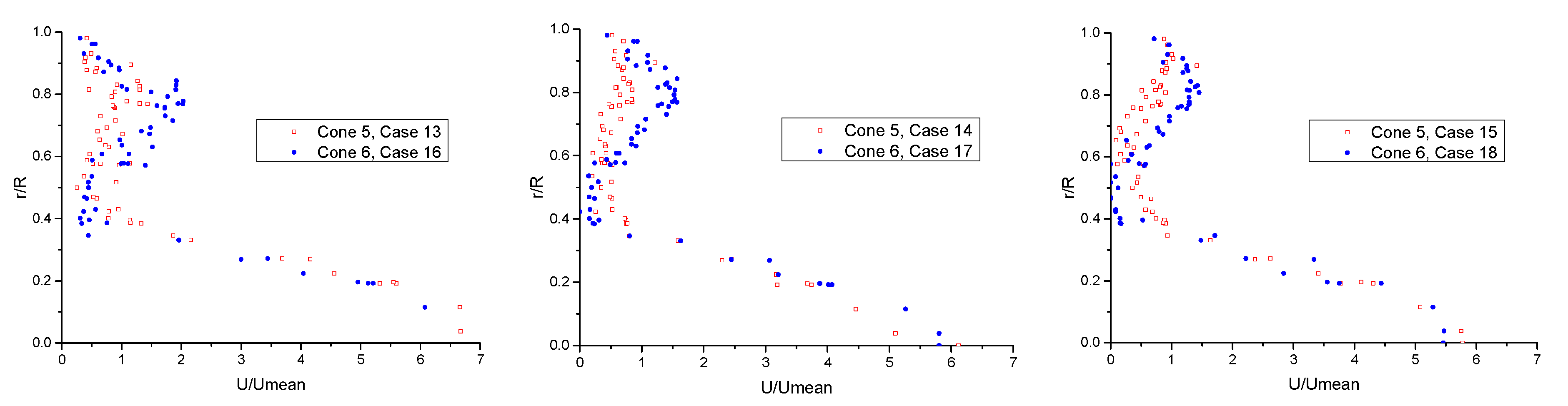
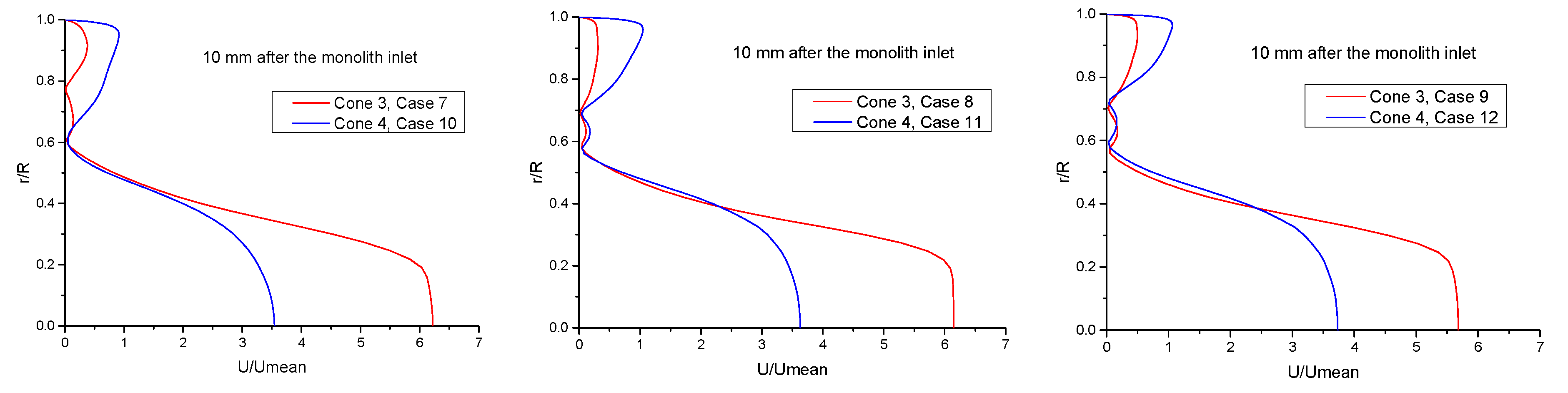
4.2. Velocity Profile
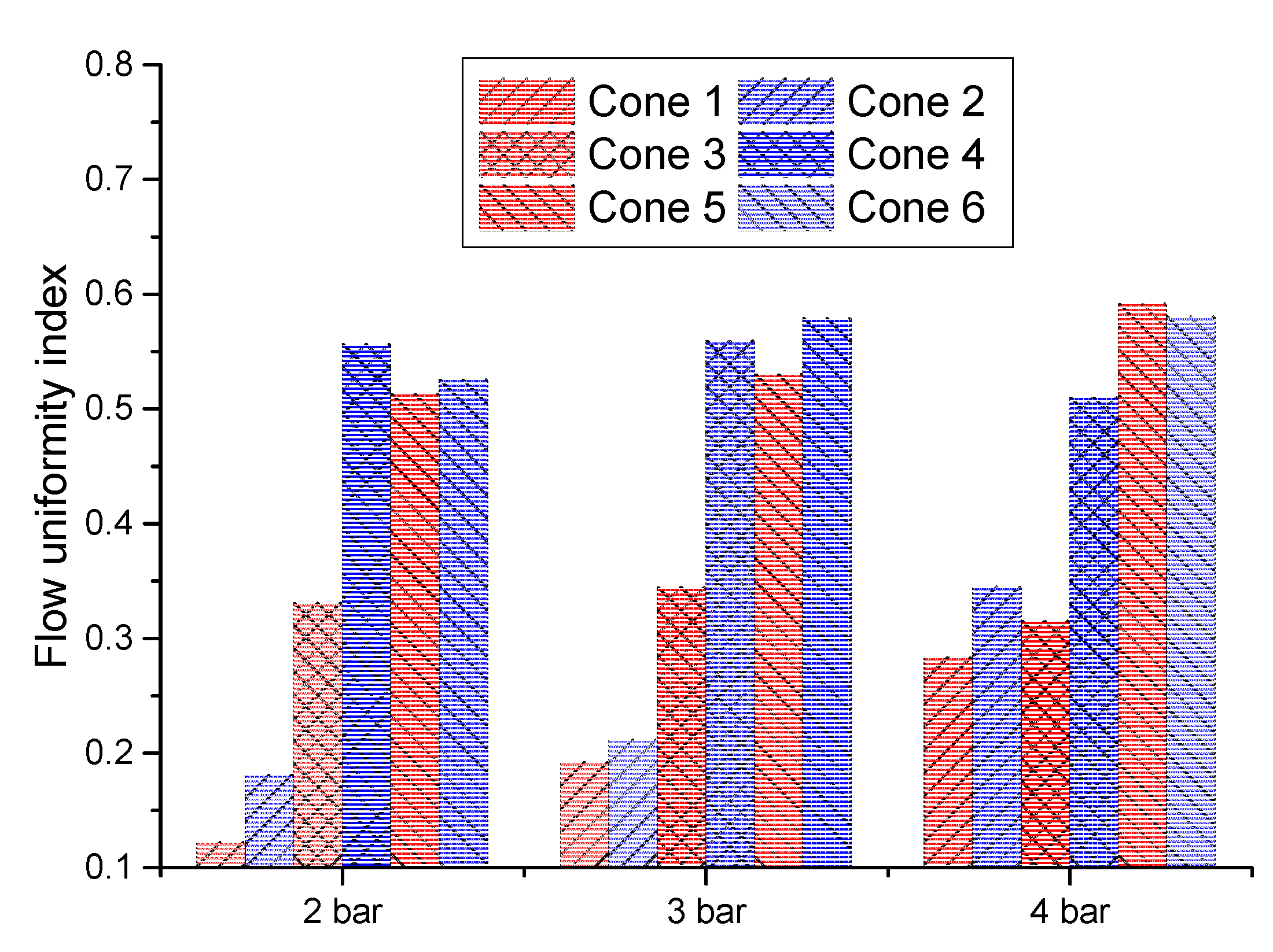
4.3. Flow Uniformity
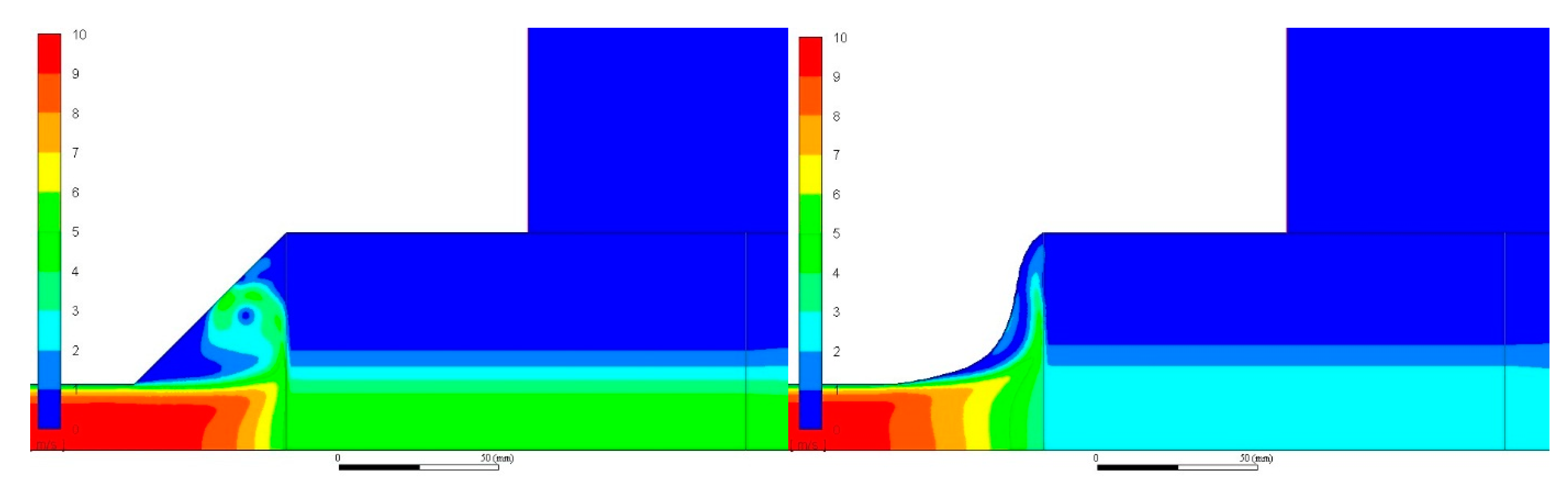
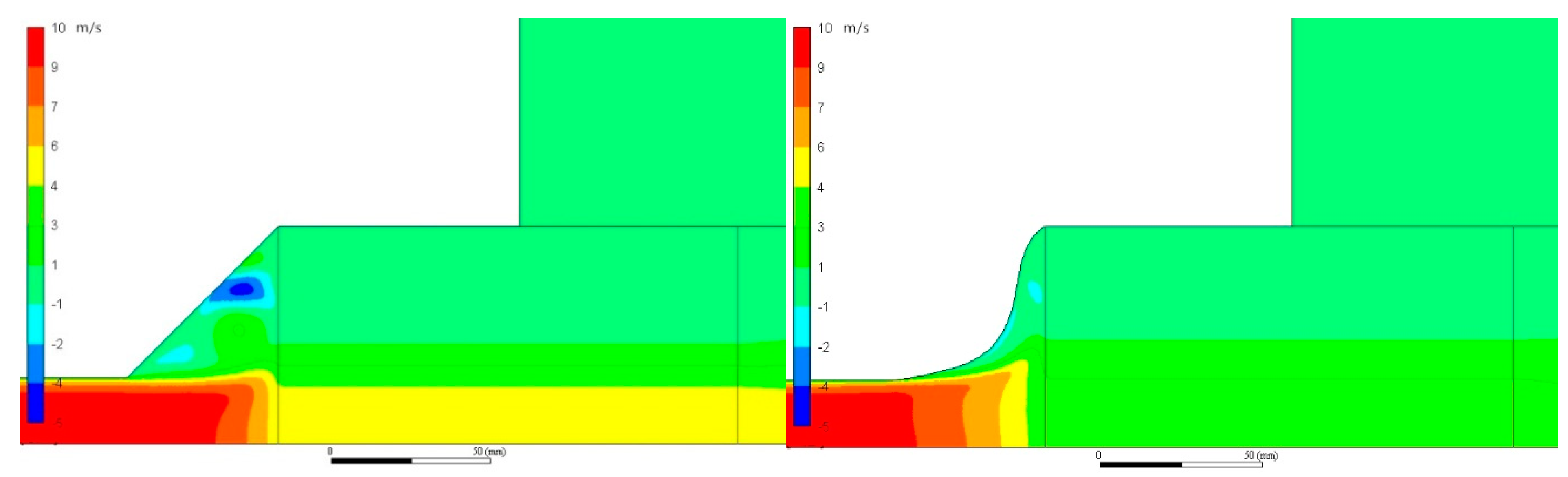
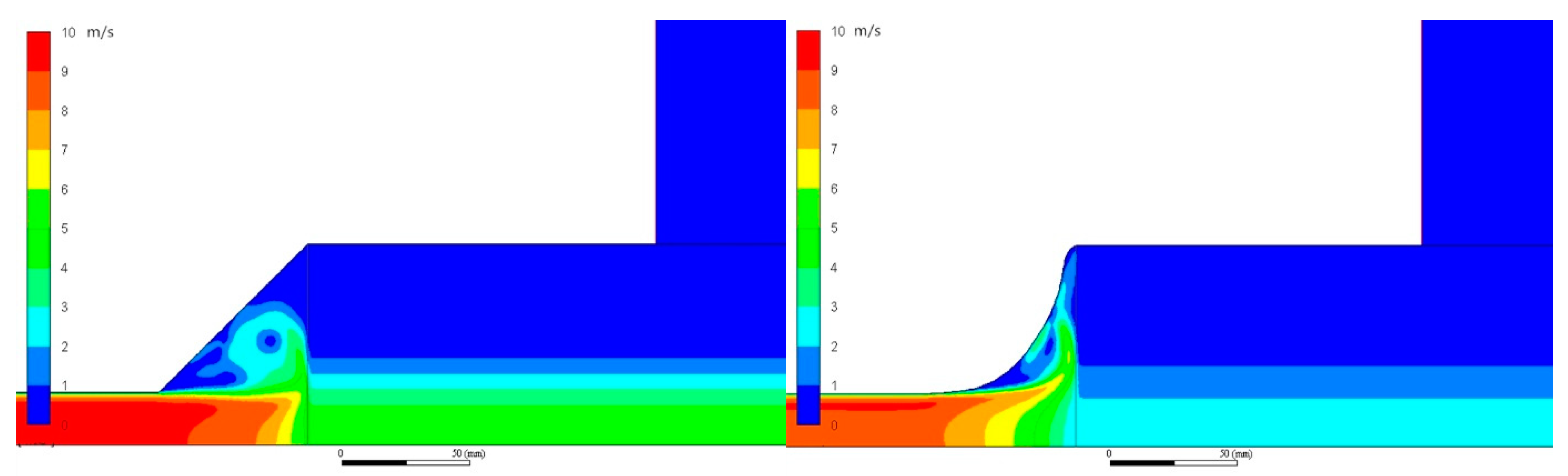
4.4. CFD Velocity Profiles
4.5. Future Work
5. Conclusions
Author Contributions
Funding
Acknowledgments
Conflicts of Interest
Nomenclature
| Reynolds-averaged velocity (m/s) | |
| Time (s) | |
| Pressure (Pa) | |
| Strain tensor (1/s) | |
| Inertial resistance factor | |
| Identity matrix | |
| Channel hydraulic diameter (m) | |
| Permeability (m2) | |
| Wilcox —ω model parameter | |
| Wilcox —ω model parameter | |
| Wilcox —ω model parameter | |
| Rate of viscous dissipation (m2/s2) | |
| Turbulence kinetic energy (m2/s2) | |
| Viscosity (Pa) | |
| Turbulence viscosity (Pa·s) | |
| Density (kg/m3) | |
| Turbulence Prandtl number for ω | |
| Turbulence Prandtl number for | |
| Monolith porosity | |
| Specific dissipation ratio |
Abbreviations
| EATS | Exhaust after-treatment system |
| DOC | Diesel oxidation catalyst |
| DPF | Diesel particulate filter |
| GPF | Gasoline particulate filter |
| SCR | Selective catalytic reduction |
| LNT | Lean NOx trap |
| PM | Particulate matter |
| RANS | Reynolds-averaged Navier–Stokes equations |
| VANS | Volume-averaged Navier–Stokes equations |
References
- Meloni, R.; Naso, V. An insight into the effect of advanced injection strategies on pollutant emissions of a heavy-duty diesel engine. Energies 2013, 6, 4331–4351. [Google Scholar] [CrossRef]
- Raza, M.; Chen, L.F.; Leach, F.; Ding, S.T. A review of Particulate Number (PN) emissions from Gasoline Direct Injection (GDI) engines and their control techniques. Energies 2018, 11, 1417. [Google Scholar] [CrossRef]
- Okubo, M.; Kuroki, T.; Kawasaki, S.; Yoshida, K.; Yamamoto, T. Continuous regeneration of ceramic particulate filter in stationary diesel engine by Nonthermal-Plasma-Induced ozone injection. IEEE Trans. Ind. Appl. 2009, 45, 1568–1574. [Google Scholar] [CrossRef]
- Wang, D.; Liu, Z.C.; Tian, J.; Liu, J.W.; Zhang, J.R. Investigation of particle emission characteristics from a diesel engine with a diesel particulate filter for alternative fuels. Int. J. Automot. Technol. 2012, 13, 1023–1032. [Google Scholar] [CrossRef]
- Zhang, B.E.J.; Gong, J.; Yuan, W.; Zhao, X.; Hu, W. Influence of structural and operating factors on performance degradation of the diesel particulate filter based on composite regeneration. Appl. Therm. Eng. 2017, 121, 838–852. [Google Scholar] [CrossRef]
- Laurell, M.; Sjörs, J.; Ovesson, S.; Lundgren, M. The innovative exhaust gas aftertreatment system for the new Volvo 4 Cylinder Engines; a unit catalyst system for gasoline and diesel cars. In Proceedings of the 22nd Aachen Colloquium Automobile and Engine Technology, Aachen, Germany, 2–3 July 2015. [Google Scholar]
- Konstandopoulos, A.G.; Skaperdas, E.; Masoudi, M. Inertial contributions to the pressure drop of diesel particulate filters. SAE Tech. Pap. 2001. [Google Scholar] [CrossRef]
- Haralampous, O.A.; Kandylas, I.P.; Koltsakis, G.C.; Samaras, Z.C.; Haralampous, O.A. Diesel particulate filter pressure drop Part 1: Modelling and experimental validation. Int. J. Engine Res. 2004, 5, 149–162. [Google Scholar] [CrossRef]
- Masoudi, M. Pressure drop of segmented diesel particulate filters. SAE Tech. Pap. 2005. [Google Scholar] [CrossRef]
- Torregrosa, A.J.; Serrano, J.R.; Arnau, F.J.; Piqueras, P. A fluid dynamic model for unsteady compressible flow in wall-flow diesel particulate filters. Energy 2011, 36, 671–684. [Google Scholar] [CrossRef]
- Myung, C.L.; Kim, J.; Jang, W.; Jin, D.; Park, S.; Lee, J. Nanoparticle filtration characteristics of advanced metal foam media for a spark ignition direct injection engine in steady engine operating conditions and vehicle test modes. Energies 2015, 8, 1865–1881. [Google Scholar] [CrossRef]
- Shuja, S.Z.; Habib, M.A. Fluid flow and heat transfer characteristics in axisymmetric annular diffusers. Comput. Fluids 1996, 25, 133–150. [Google Scholar] [CrossRef]
- Ubertini, S.; Desideri, U. Experimental performance analysis of an annular diffuser with and without struts. Exp. Therm. Fluid Sci. 2000, 22, 183–195. [Google Scholar] [CrossRef]
- Neve, R.S. Computational fluid dynamics analysis of diffuser performance in gas-powered jet pumps. Int. J. Heat Fluid Flow 1993, 14, 401–407. [Google Scholar] [CrossRef]
- Forrester, S.E.; Evans, G.M. Computational modelling study of the hydrodynamics in a sudden—Tapered contraction reactor geometry. Chem. Eng. Sci. 1997, 52, 3773–3785. [Google Scholar] [CrossRef]
- Karvounis, E.; Assanis, D.N. The effect of inlet flow distribution on catalytic conversion efficiency. Int. J. Heat Mass Transf. 1993, 36, 1495–1504. [Google Scholar] [CrossRef]
- Ozhan, C.; Fuster, D.; Da Costa, P. Multi-scale flow simulation of automotive catalytic converters. Chem. Eng. Sci. 2014, 116, 161–171. [Google Scholar] [CrossRef]
- Ma, L.; Paraschivoiu, M.; Yao, J.; Blackman, L. Improving flow uniformity in a diesel particulate filter system. SAE Tech. Pap. 2001. [Google Scholar] [CrossRef]
- Lai, M.C.; Kim, J.Y.; Cheng, C.Y.; Li, P.; Chui, G.; Pakko, J.D. Three-dimensional simulations of automotive catalytic converter internal flow. SAE Trans. 1991, 100, 241–250. [Google Scholar]
- Chakravarthy, V.K.; Conklin, J.C.; Daw, C.S.; D’Azevedo, E.F. Multi-dimensional simulations of cold-start transients in a catalytic converter under steady inflow conditions. Appl. Catal. A-Gen. 2003, 241, 289–306. [Google Scholar] [CrossRef]
- Howitt, J.S.; Sekella, T.C. Flow effects in monolithic honeycomb automotive catalytic converters. SAE. Tech. Pap. 1974. [Google Scholar] [CrossRef]
- Bella, G.; Rocco, V.; Maggiore, M. A study of inlet flow distortion effects on automotive catalytic converters. J. Eng. Gas Turbines Power 1991, 113, 419. [Google Scholar] [CrossRef]
- Wendland, D.W.; Matthes, W.R. Visualization of automotive catalytic converter internal flows. SAE. Tech. Pap. 1986. [Google Scholar] [CrossRef]
- Kulkarni, G.S.; Singh, S.N.; Seshadri, V.; Mohan, R. Optimum diffuser geometry for the automotive catalytic converter. Indian J. Eng. Mater. Sci. 2003, 10, 5–13. [Google Scholar]
- Stratakis, G.A.; Stamatelos, A.M. Mow maldistribution measurements in wall-flow diesel filters. Proc. Inst. Mech. Eng. Part D-J. Automob. Eng. 2004, 218, 995–1009. [Google Scholar] [CrossRef]
- Weltens, H.; Bressler, H.; Terres, F.; Neumaier, H.; Rammoser, D. Optimisation of catalytic converter gas flow distribution by CFD prediction. SAE. Tech. Pap. 1993. [Google Scholar] [CrossRef]
- Badami, M.; Millo, F.; Zuarini, A.; Gambarotto, M. CFD analysis and experimental validation of the inlet flow distribution in close coupled catalytic converters. SAE Tech. Pap. 2003. [Google Scholar] [CrossRef]
- Salasc, S.; Barrieu, E.; Leroy, V. Impact of manifold design on flow distribution of a close-coupled catalytic converter. SAE Tech. Pap. 2005. [Google Scholar] [CrossRef]
- Jiaqiang, E.; Liu, M.; Deng, Y.; Zhu, H.; Gong, J. Influence analysis of monolith structure on regeneration temperature in the process of microwave regeneration in the diesel particulate filter. Can. J. Chem. Eng. 2016, 94, 168–174. [Google Scholar]
- Wang, X.R.; Wang, Z.Q.; Wang, Y.S.; Lin, T.S.; He, P. A bisection method for the milling of NURBS mapping projection curves by CNC machines. Int. J. Adv. Manuf. Technol. 2017, 91, 155–164. [Google Scholar] [CrossRef]
- Zhou, W.; Liu, B.; Wang, Q.; Cheng, Y.; Ma, G.; Chang, X.; Chen, X. NURBS-enhanced boundary element method based on independent geometry and field approximation for 2D potential problems. Eng. Anal. Bound. Elem. 2017, 83, 158–166. [Google Scholar] [CrossRef]
- Coelho, M.; Roehl, D.; Bletzinger, K.U. Material model based on NURBS response surfaces. Appl. Math. Model. 2017, 51, 574–586. [Google Scholar] [CrossRef]
- Mu, M.; Li, X.; Aslam, J.; Qiu, Y.; Yang, H.; Kou, G.; Wang, Y. A study of shape optimization method on connection cones for diesel particulate filter (DPF). In Proceedings of the ASME 2016 International Mechanical Engineering Congress and Exposition, Phoenix, AZ, USA, 11–17 November 2016; p. V012T16A001. [Google Scholar]
- Strom, H.; Sasic, S.; Andersson, B. Design of automotive flow-through catalysts with optimized soot trapping capability. Chem. Eng. J. 2010, 165, 934–945. [Google Scholar] [CrossRef]
- Versteeg, H.K.; Malalasekera, W. An Introduction to Computational Fluid Dynamics: The Finite Volume Method; Pearson Education Limited: Essex, UK, 2007. [Google Scholar]
- Menter, F.R. Two-equation eddy-viscosity turbulence models for engineering applications. Aiaa J. 1994, 32, 1598–1605. [Google Scholar] [CrossRef]
- Menter, F.R. Eddy viscosity transport equations and their relation to the k-ɛ model. J. Fluids Eng. 1997, 119, 876. [Google Scholar] [CrossRef]
- Ishak, M.H.H.; Ismail, F.; Che Mat, S.; Abdullah, M.Z.; Aziz, M.S.A.; Idroas, M.Y. Numerical analysis of nozzle flow and spray characteristics from different nozzles using diesel and biofuel blends. Energies 2019, 12, 281. [Google Scholar] [CrossRef]
- Wilcox, D.C. Reassessment of the scale-determining equation for advanced turbulence models. Aiaa J. 1988, 26, 1299–1310. [Google Scholar] [CrossRef]
- Wilcox, D.C. Turbulence Modeling for CFD; DCW Industries: Flintridge, CA, USA, 2006; pp. 363–367. [Google Scholar]
- Masoudi, M. Hydrodynamics of diesel particulate filters. SAE Tech. Pap. 2002. [Google Scholar] [CrossRef]
- Jiao, G.; Liu, H.; Yang, L.; Li, C. Simulation of catalytic combustion flows in honeycomb reactors. J. Beijing Univ. Chem. Technol. 2004, 2, 1–5. [Google Scholar]
- Hayes, R.E.; Fadic, A.; Mmbaga, J.; Najafi, A. CFD modelling of the automotive catalytic converter. Catal. Today 2012, 188, 94–105. [Google Scholar] [CrossRef]
- Ekström, F.; Andersson, B. Pressure drop of monolithic catalytic converters experiments and modeling. SAE Tech. Pap. 2003. [Google Scholar] [CrossRef]
- Cornejo, I.; Nikrityuk, P.A.; Hayes, R.E. Turbulence decay inside the channels of an automotive catalytic converter monolith. Emiss. Control Sci. Technol. 2017, 3, 302–309. [Google Scholar] [CrossRef]
- Cornejo, I.; Nikrityuk, P.A.; Hayes, R.E. Multiscale RANS-based modeling of the turbulence decay inside of an automotive catalytic converter. Chem. Eng. Sci. 2018, 175, 377–386. [Google Scholar] [CrossRef]


| Criteria | Cone 1 | Cone 2 | Cone 3 | Cone 4 | Cone 5 | Cone 6 |
|---|---|---|---|---|---|---|
| Pipe Diameter d, mm | 21 | 21 | 27.3 | 27.3 | 27.3 | 27.3 |
| Monolith Diameter D, mm | 90 | 90 | 90 | 90 | 104 | 104 |
| Cone Length L, mm | 31.35 | 31.35 | 31.35 | 31.35 | 38.35 | 38.35 |
| Cone Type | Conventional | NURBS | Conventional | NURBS | Conventional | NURBS |
| Monolith Type | DOC | DOC | DOC | DOC | GPF | GPF |
| Cone # | Monolith Type | Case # | Pressure Regulator, bar | Volumetric Flow, L/s |
|---|---|---|---|---|
| Cone 1 | DOC | Case 1 | 2 | 4.32 |
| Case 2 | 3 | 7.7 | ||
| Case 3 | 4 | 11.19 | ||
| Cone 2 | DOC | Case 4 | 2 | 4.53 |
| Case 5 | 3 | 7.83 | ||
| Case 6 | 4 | 11.19 | ||
| Cone 3 | DOC | Case 7 | 2 | 4.81 |
| Case 8 | 3 | 8.79 | ||
| Case 9 | 4 | 12.86 | ||
| Cone 4 | DOC | Case 10 | 2 | 4.65 |
| Case 11 | 3 | 8.43 | ||
| Case 12 | 4 | 12.12 | ||
| Cone 5 | GPF | Case 13 | 2 | 4.89 |
| Case 14 | 3 | 8.59 | ||
| Case 15 | 4 | 12.19 | ||
| Cone 6 | GPF | Case 16 | 2 | 4.76 |
| Case 17 | 3 | 8.46 | ||
| Case 18 | 4 | 12.17 |
| Material | Value | |
|---|---|---|
| Fluid | Air-Incompressible | |
| Porous Medium Specifications | Axial permeability, m2 | 1.835 × 10⁻⁷ |
| Radial permeability, m2 | 1.835 × 10⁻¹⁰ | |
| Converter Boundary Conditions | Inlet-Velocity inlet, m/s | 8.22 |
| Inlet-Turbulence intensity, % | 5 | |
| Inlet-Hydraulic diameter, mm | 27.3 | |
| Outlet | 0 Pa | |
| Walls | No-slip wall | |
| Symmetry axis | Axial symmetry | |
| Settings | Viscous model | k-omega |
| Pressure-Velocity coupling | SIMPLE | |
| Momentum scheme | QUICK | |
| Turbulence kinetic energy scheme | QUICK | |
| Specific dissipation rate scheme | QUICK | |
| d mm | D mm | Length mm | Monolith type | Monolith Volume, L | Space Velocity, ×104 h−1 | Pressure Drop Per Flow Volume of Conventional Cone, Pa·s/L | Pressure Drop Per Flow Volume of NURBS Cone, Pa·s/L | Reduction Ratio |
|---|---|---|---|---|---|---|---|---|
| 21 | 90 | 95 | DOC | 0.604 | 2.6 | 148.58 | 135.34 | 0.09 |
| 4.6 | 147.08 | 133.30 | 0.09 | |||||
| 6.6 | 157.89 | 142.82 | 0.10 | |||||
| 27.3 | 90 | 95 | DOC | 0.604 | 2.81 | 51.81 | 45.67 | 0.12 |
| 5.1 | 49.07 | 43.43 | 0.11 | |||||
| 7.4 | 52.14 | 45.63 | 0.12 | |||||
| 27.3 | 104 | 140 | GPF | 1.189 | 1.4 | 51.63 | 50.80 | 0.02 |
| 2.58 | 50.43 | 48.96 | 0.03 | |||||
| 3.69 | 53.77 | 52.15 | 0.03 |
© 2019 by the authors. Licensee MDPI, Basel, Switzerland. This article is an open access article distributed under the terms and conditions of the Creative Commons Attribution (CC BY) license (http://creativecommons.org/licenses/by/4.0/).
Share and Cite
Mu, M.; Sjöblom, J.; Ström, H.; Li, X. Analysis of the Flow Field from Connection Cones to Monolith Reactors. Energies 2019, 12, 455. https://doi.org/10.3390/en12030455
Mu M, Sjöblom J, Ström H, Li X. Analysis of the Flow Field from Connection Cones to Monolith Reactors. Energies. 2019; 12(3):455. https://doi.org/10.3390/en12030455
Chicago/Turabian StyleMu, Mingfei, Jonas Sjöblom, Henrik Ström, and Xinghu Li. 2019. "Analysis of the Flow Field from Connection Cones to Monolith Reactors" Energies 12, no. 3: 455. https://doi.org/10.3390/en12030455
APA StyleMu, M., Sjöblom, J., Ström, H., & Li, X. (2019). Analysis of the Flow Field from Connection Cones to Monolith Reactors. Energies, 12(3), 455. https://doi.org/10.3390/en12030455