Performance Analysis of a Hybrid System Consisting of a Molten Carbonate Direct Carbon Fuel Cell and an Absorption Refrigerator


Abstract
1. Introduction
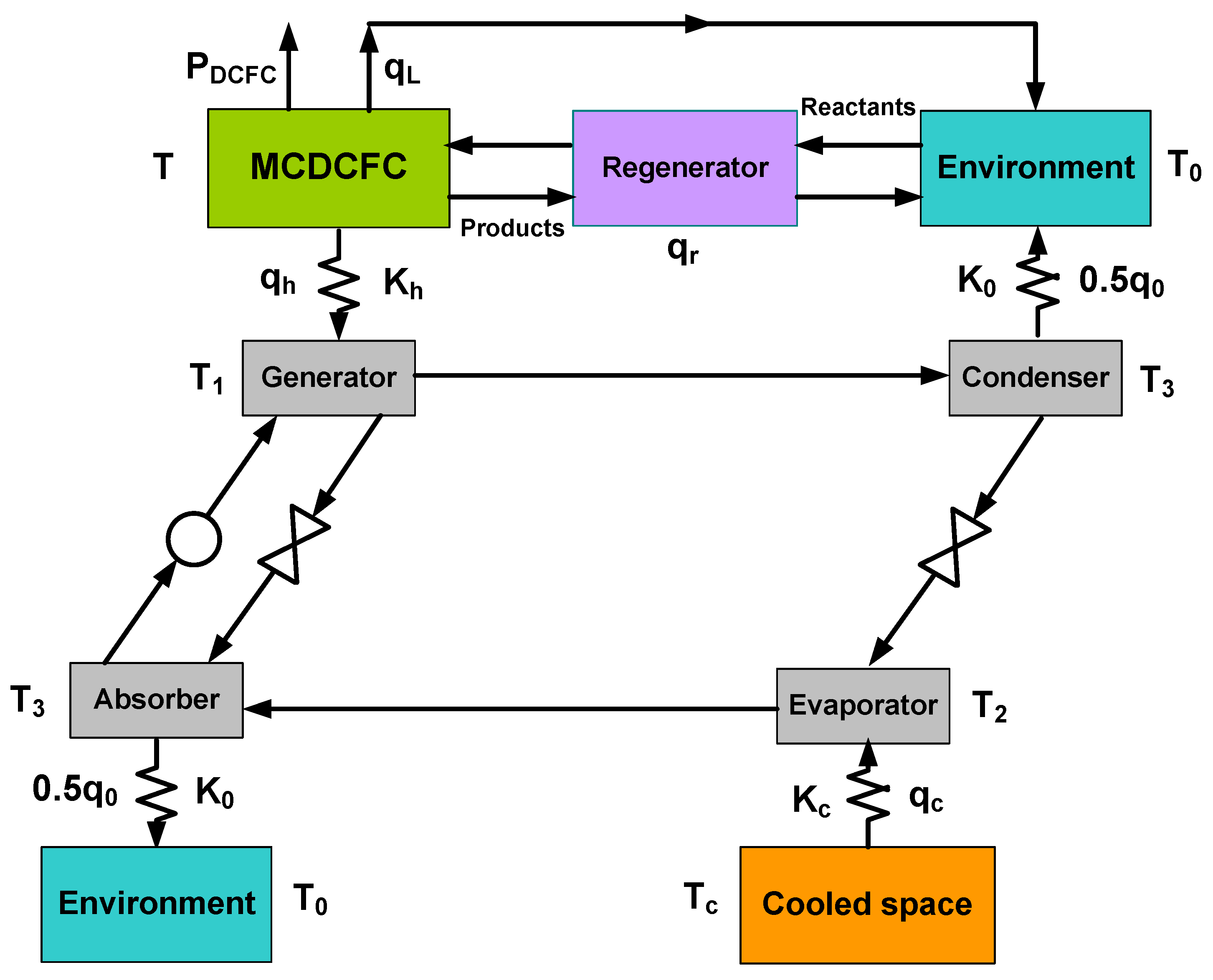
2. System Description
- Both the MCDCFC and the AR are operated under steady-state conditions;
- Operating temperature and pressure are uniform and constants in the MCDCFC;
- Chemical reactions involved are complete;
- All gases involved are ideal gases;
- Carbon fuel is regarded as a rigid sphere and packed with a simple hexagonal pattern;
- Electrical power required to compress the reactants is excluded in the calculations;
- Working fluid in the AR constantly flows and continuously exchanges heat with the three heat reservoirs;
- Heat transfers within the system obey Newton’s law.
2.1. MCDCFC
2.2. Absorption Refrigerator
2.3. Regenerator
2.4. Performance Parameter of the Hybrid System
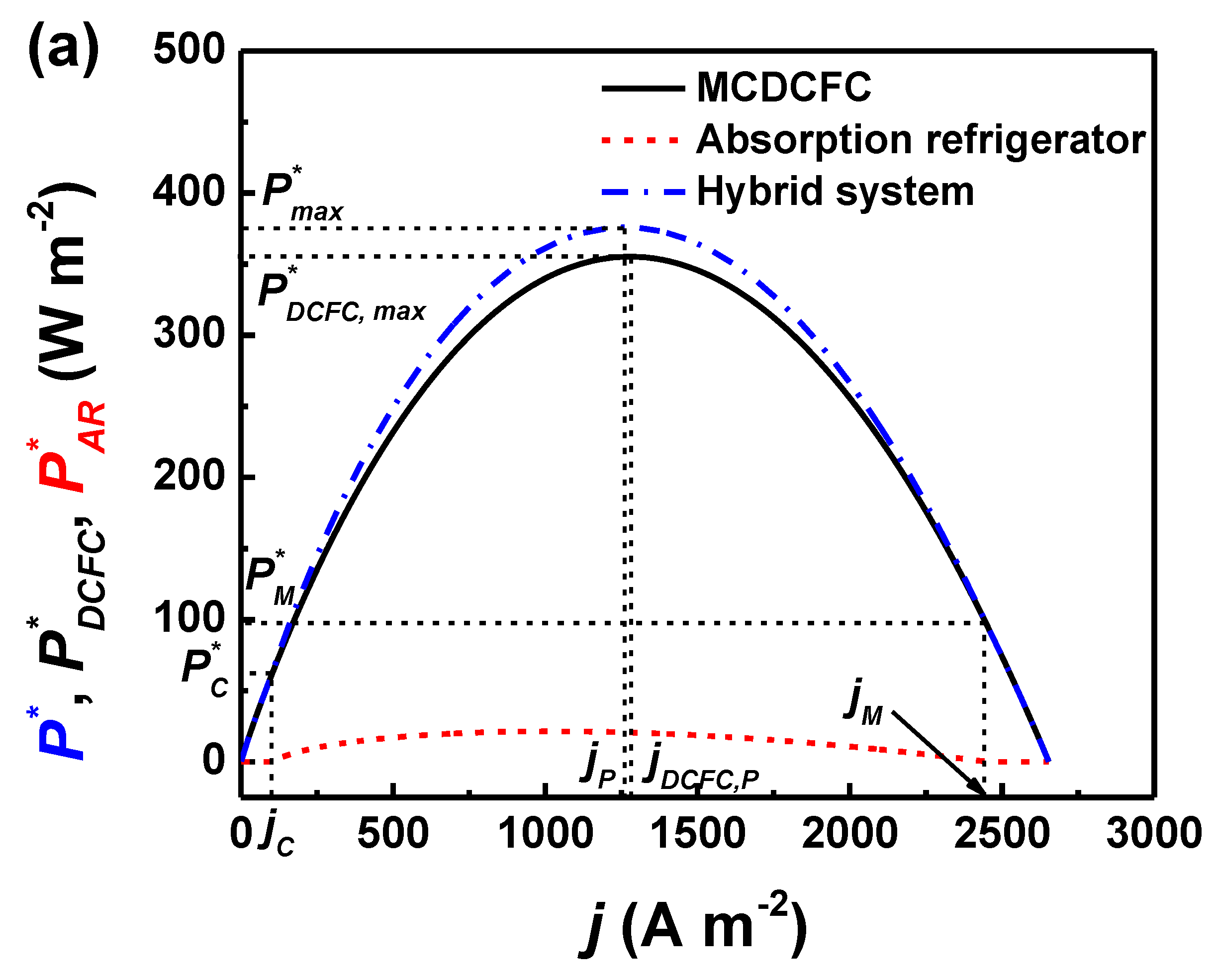
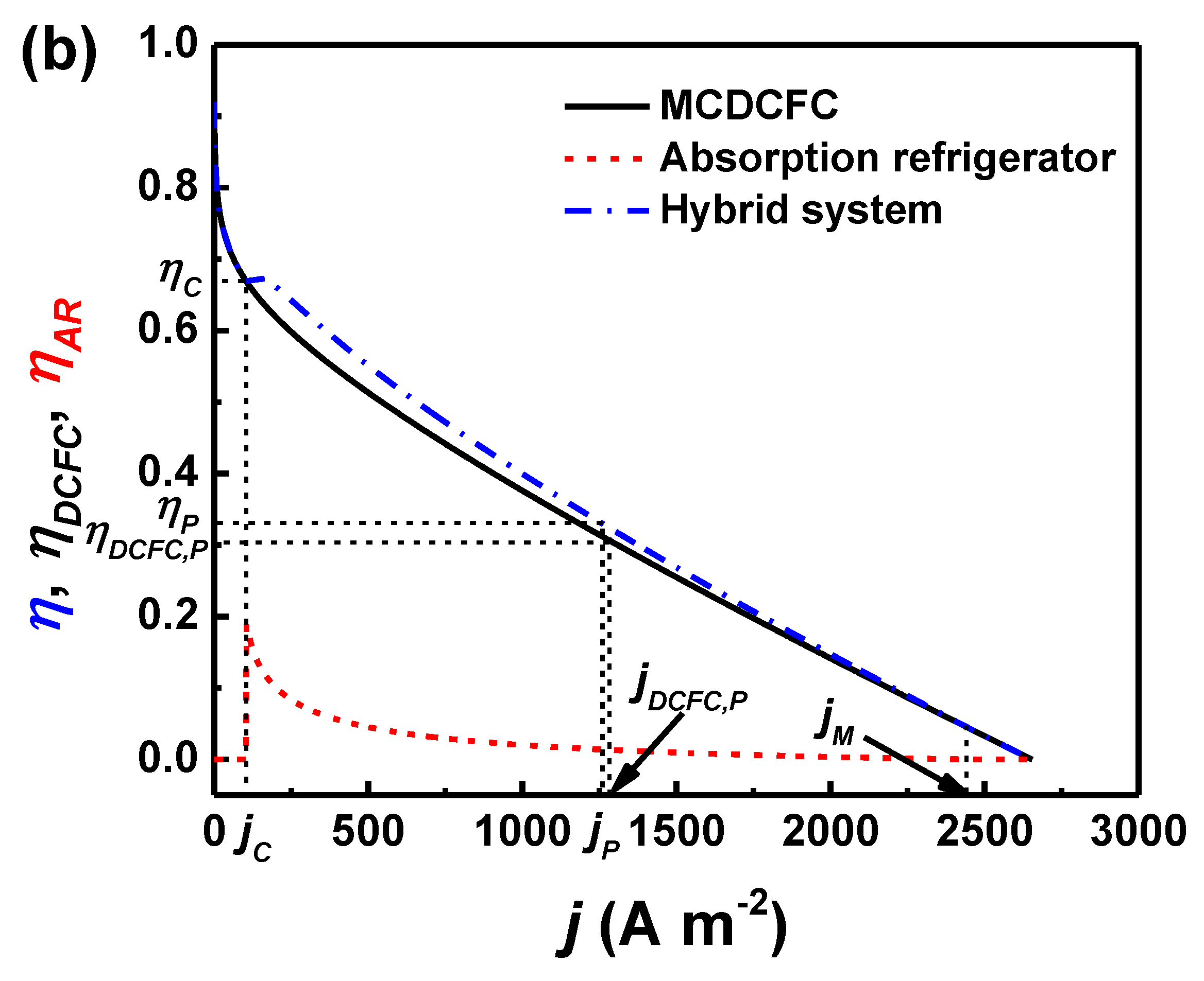
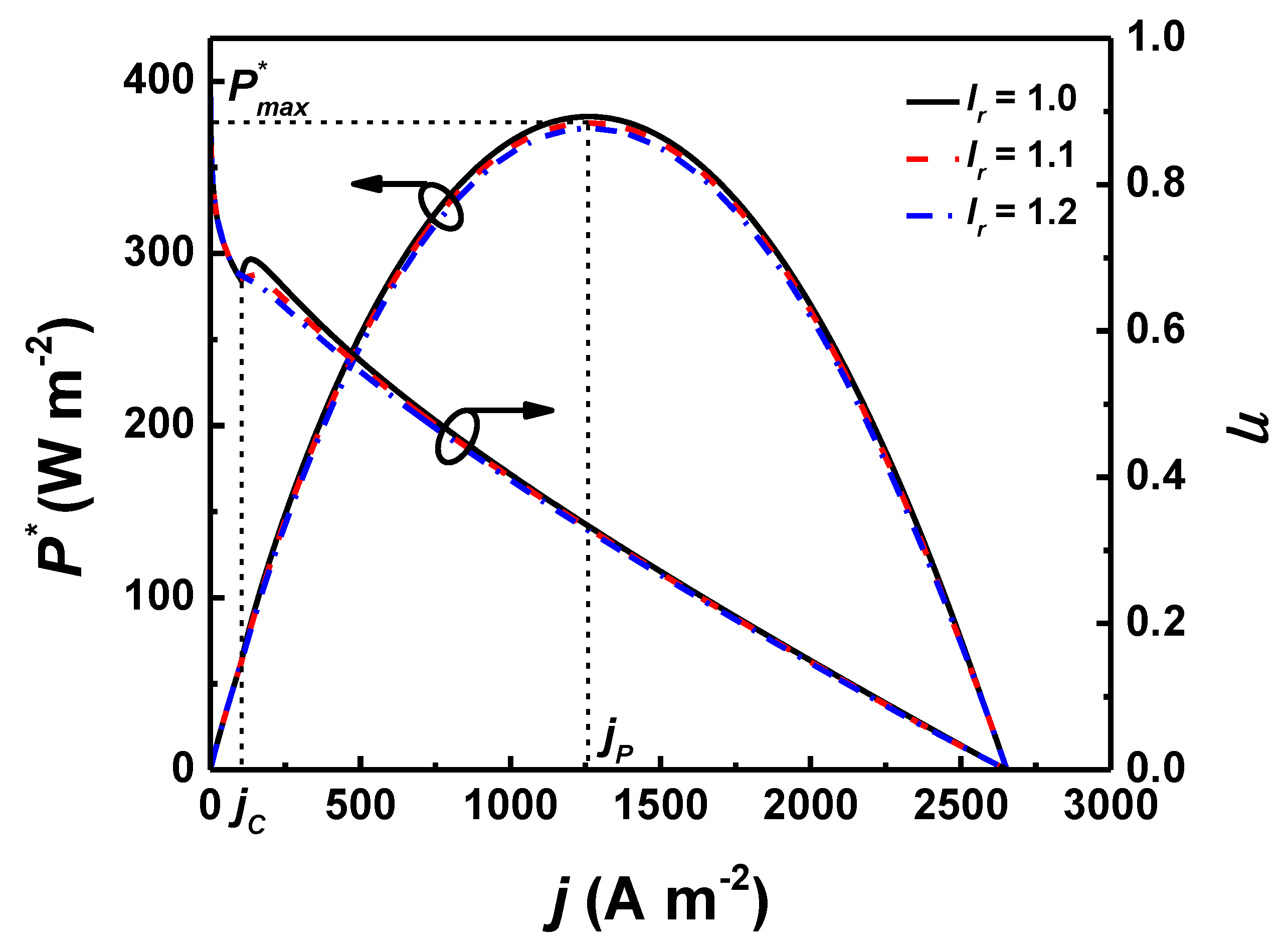
3. Performance Characteristic and Optimum Operating Region
4. Results and Discussion
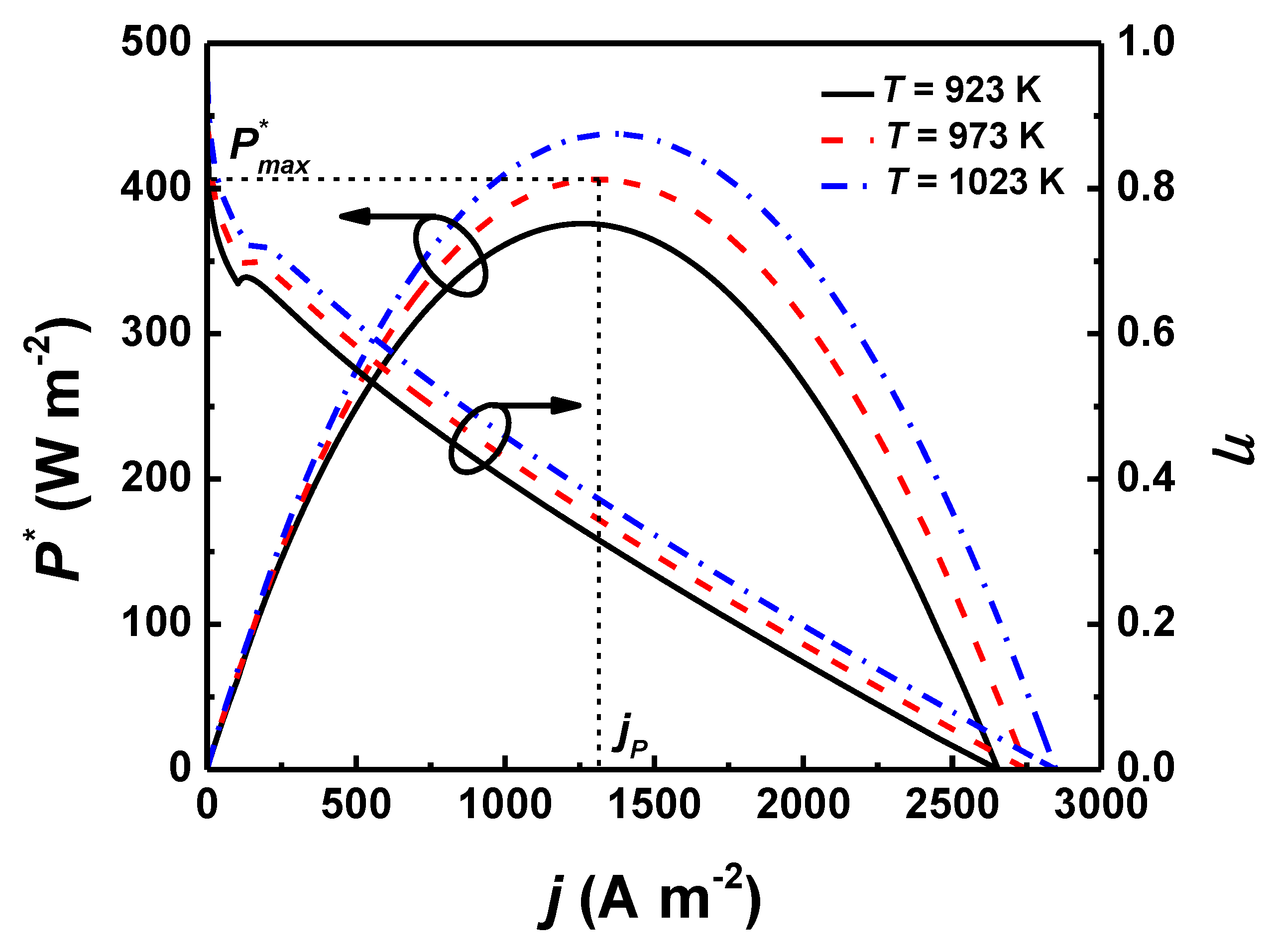
4.1. Effects of
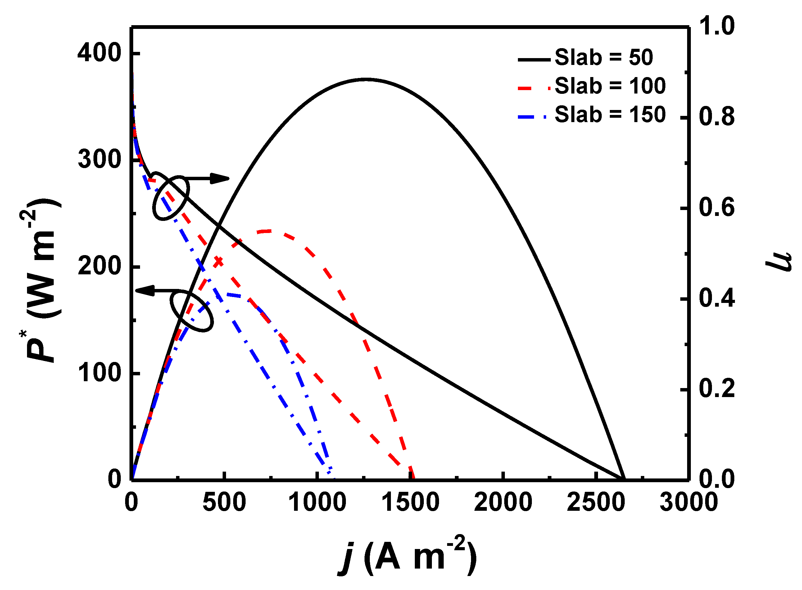
4.2. Effects of Anode Thickness
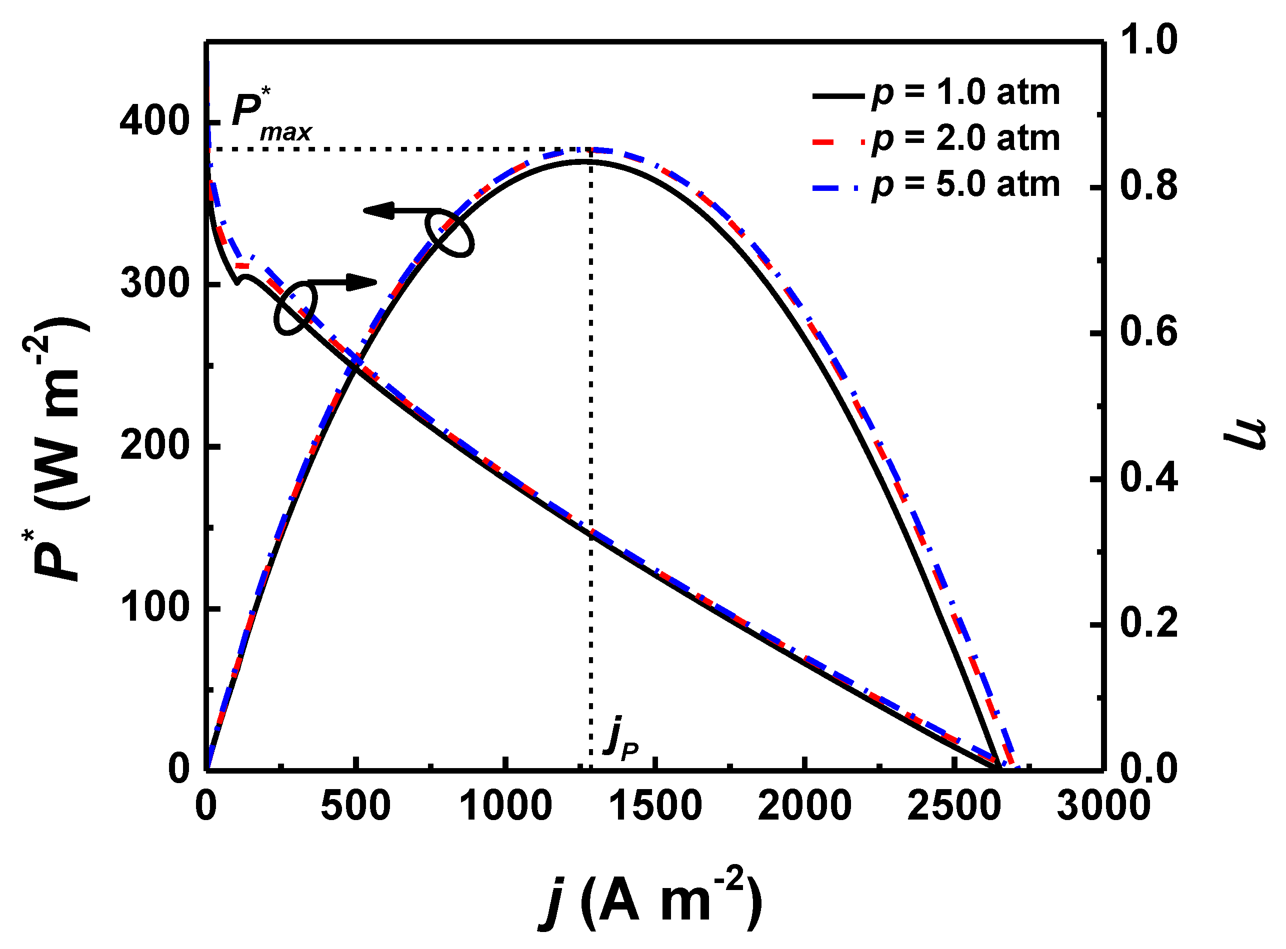
4.3. Effects of
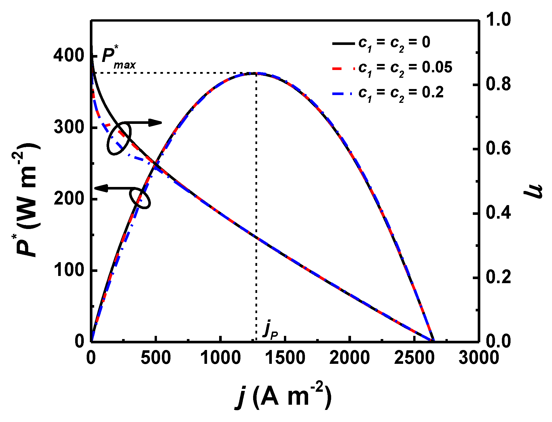
4.4. Effects of and/or
4.5. Effects of
5. Conclusions
Author Contributions
Funding
Conflicts of Interest
References
- Asif, M.; Muneer, T. Energy supply, its demand and security issues for developed and emerging economics. Renew. Sust. Energy Rev. 2007, 11, 1388–1413. [Google Scholar] [CrossRef]
- Jiang, C.; Ma, J.; Corre, G.; Jain, S.; Irvine, J.T.S. Challenges in developing direct carbon fuel cells. Chem. Soc. Rev. 2017, 46, 2889–2912. [Google Scholar] [CrossRef] [PubMed]
- Cao, D.; Sun, Y.; Wang, G. Direct carbon fuel cell: Fundamentals and recent developments. J. Power Sources 2007, 167, 250–257. [Google Scholar] [CrossRef]
- Bischoff, M. Molten carbonate fuel cells: A high temperature fuel cell on the edge to commercialization. J. Power Sources 2006, 160, 842–845. [Google Scholar] [CrossRef]
- Cai, W.; Zhou, Q.; Xie, Y.; Liu, J.; Long, G.; Cheng, S.; Liu, M. A direct carbon solid oxide fuel cell operated on a plant derived biofuel with natural catalyst. Appl. Energy 2016, 179, 1232–1241. [Google Scholar] [CrossRef]
- Cai, W.; Zhou, Q.; Xie, Y.; Liu, J. A facile method of preparing Fe-loaded activated carbon fuel for direct carbon solid oxide fuel cells. Fuel 2015, 159, 887–893. [Google Scholar] [CrossRef]
- Zhang, H.; Chen, J.; Zhang, J. Performance analysis and parametric study of a solid oxide fuel cell fueled by carbon monoxide. Int. J. Hydrog. Energy 2013, 38, 16354–16364. [Google Scholar] [CrossRef]
- Kacprzak, A.; Kobylechi, R.; Bis, Z. Influence of temperature and composition of NaOH-KOH and NaOH-LiOH electrolytes on the performance of a direct carbon fuel cell. J. Power Sources 2013, 239, 409–414. [Google Scholar] [CrossRef]
- Guo, L.; Calo, J.M.; DiCocco, E.; Bain, E.J. Development of a low temperature, molten hydroxide direct carbon fuel cell. Energy Fuels 2013, 27, 1712–1719. [Google Scholar] [CrossRef]
- Zhang, H.; Chen, L.; Zhang, J.; Chen, J. Performance analysis of a direct carbon fuel cell with molten carbonate electrolyte. Energy 2014, 68, 292–300. [Google Scholar] [CrossRef]
- Cooper, J.F.; Selman, J.R. Analysis of the carbon anode in direct carbon conversion fuel cells. Int. J. Hydrog. Energy 2012, 37, 19319–19328. [Google Scholar]
- Cherepy, N.J.; Krueger, R.; Fiet, K.J.; Jankowski, A.F.; Cooper, J.F. Direct conversion of carbon fuels in a molten carbonate fuel cell. J. Electrochem. Soc. 2005, 152, A80–A87. [Google Scholar] [CrossRef]
- Li, X.; Zhu, H.; De Marco, R.; Dicks, A.; Bradley, J.; Liu, S.; Lu, G.Q. Factors that determine the performance of carbon fuels in the direct carbon fuel cell. Ind. Eng. Chem. Res. 2008, 47, 9670–9677. [Google Scholar] [CrossRef]
- Glenn, M.J.; Allen, J.A.; Donne, S.W. Thermal investigation of a doped alkali-metal carbonate ternary eutectic for direct carbon fuel cell applications. Energy Fuels 2015, 29, 5423–5433. [Google Scholar] [CrossRef]
- Watanabe, H.; Kimura, A.; Okazaki, K. Impact of ternary carbonate composition on the morphology of the carbon/carbonate slurry and continuous power generation by direct carbon fuel cells. Energy Fuels 2016, 30, 1835–1840. [Google Scholar] [CrossRef]
- Bonaccorso, A.D.; Irvine, J.T.S. Development of tubular hybrid direct carbon fuel cell. Int. J. Hydrog. Energy 2012, 37, 19337–19344. [Google Scholar] [CrossRef]
- Hao, W.; Mi, Y. Evaluation of waste paper as a source of carbon fuel for hybrid direct carbon fuel cells. Energy 2016, 107, 122–130. [Google Scholar] [CrossRef]
- Elleuch, A.; Boussetta, A.; Halouani, K.; Li, Y. Experimental investigation of Direct Carbon Fuel Cell fueled by almond shell biochar: Part II. Improvement of cell stability and performance by a three-layer planar configuration. Int. J. Hydrog. Energy 2013, 38, 16605–16614. [Google Scholar] [CrossRef]
- Jiang, C.; Ma, J.; Arenillas, A.; Bonaccorso, A.D.; Irvine, J.T.S. Comparative study of durability of hybrid direct carbon fuel cells with anthracite coal and bituminous coal. Int. J. Hydrog. Energy 2016, 41, 18797–18806. [Google Scholar] [CrossRef]
- Giddey, S.; Badwal, S.P.S.; Kulkarni, A.; Munnings, C. A comprehensive review of direct carbon fuel cell technology. Prog. Energy Comb. Sci. 2012, 38, 360–399. [Google Scholar] [CrossRef]
- Steinberg, M. Conversion of fossil and biomass fuels to electric power and transportation fuels by high efficiency integrating plasma fuel cell (IPFC) energy cycle. Int. J. Hydrog. Energy 2006, 31, 405–411. [Google Scholar] [CrossRef]
- Zhao, M.; Zhang, H.; Hu, Z.; Zhang, Z.; Zhang, J. Performance characteristics of a direct carbon fuel cell/thermoelectric generator hybrid system. Energy Convers. Manag. 2015, 89, 683–689. [Google Scholar] [CrossRef]
- Liu, Q.; Tian, Y.; Li, H.; Jia, L.; Xia, C.; Thompson, L.T.; Li, Y. High efficiency chemical energy conversion system based on a methane catalytic decomposition reaction and two fuel cells: Part I. Process modeling and validation. J. Power Sources 2010, 195, 6539–6548. [Google Scholar] [CrossRef]
- Liu, Q.; Tian, Y.; Li, H.; Jia, L.; Xia, C.; Thompson, L.T.; Li, Y. High efficiency chemical energy conversion system based on a methane catalytic decomposition reaction and two fuel cells: Part II. Exergy analysis. J. Power Sources 2010, 195, 6532–6538. [Google Scholar] [CrossRef]
- Chen, L.; Zhang, H.; Gao, S. An available method utilizing the waste heat in a direct carbon fuel cell. Int. J. Electrochem. Sci. 2014, 9, 5788–5802. [Google Scholar]
- Srikhirin, P.; Aphornratana, S.; Chungpaibulpatana, S. A review of absorption refrigeration technologies. Renew. Sust. Energy Rev. 2001, 5, 343–373. [Google Scholar] [CrossRef]
- Ngouateu Wouagfack, P.A.; Tchinda, R. Optimal performance of an absorption refrigerator based on maximum ECOP. Int. J. Refrig. 2014, 40, 404–415. [Google Scholar] [CrossRef]
- Kim, Y.J.; Gonzalez, M. Exergy analysis of an ionic-liquid absorption refrigeration system utilizing waste-heat from datacenters. Int. J. Refrig. 2014, 48, 26–37. [Google Scholar] [CrossRef]
- Medjo Nouadje, B.A.; Ngouateu Wouagfack, P.A.; Tchinda, R. Finite-time thermodynamic optimization of an irreversible parallel flow double-effect absorption refrigerator. Int. J. Refrig. 2016, 67, 433–444. [Google Scholar] [CrossRef]
- Silveira, J.L.; Leal, E.M.; Ragonha, L.F., Jr. Analysis of a molten carbonate fuel cell: Cogeneration to produce electricity and cold water. Energy 2001, 26, 891–904. [Google Scholar] [CrossRef]
- Yang, P.; Zhang, H. Parametric analysis of an irreversible proton exchange membrane fuel cell/absorption refrigerator hybrid system. Energy 2015, 85, 458–467. [Google Scholar] [CrossRef]
- Zhao, M.; Zhao, H.; Wu, M.; Zhang, H.; Hu, Z.; Zhao, Z. Thermodynamic Analysis of a Hybrid System Integrating an Alkaline Fuel Cell with an Irreversible Absorption Refrigerator. Int. J. Electrochem. Sci. 2015, 10, 10045–10060. [Google Scholar]
- Yang, P.; Zhang, H.; Hu, Z. Parametric study of a hybrid system integrating a phosphoric acid fuel cell with an absorption refrigerator for cooling purposes. Int. J. Hydrog. Energy 2016, 41, 3579–3590. [Google Scholar] [CrossRef]
- Elleuch, A.; Boussetta, A.; Halouani, K. Analytical modeling of electrochemical mechanisms in CO2 and CO/CO2 producing direct carbon fuel cell. J. Electroanal. Chem. 2012, 668, 99–106. [Google Scholar] [CrossRef]
- Prins-Jansen, J.A.; Hemmes, K.; De Wit, J.H.W. An extensive treatment of the agglomerate model for porous electrodes in molten carbonate fuel cells-I. Qualitative analysis of the steady-state model. Electrochim. Acta 1997, 42, 3585–3600. [Google Scholar] [CrossRef]
- Liu, Q.; Tian, Y.; Xia, C.; Thompson, L.T.; Liang, B.; Li, Y. Modeling and simulation of a single direct carbon fuel cell. J. Power Sources 2008, 185, 1022–1029. [Google Scholar] [CrossRef]
- Arato, E.; Bosio, B.; Costa, P.; Parodi, F. Preliminary experimental and theoretical analysis of limit performance of molten carbonate fuel cell. J. Power Sources 2001, 102, 74–81. [Google Scholar] [CrossRef]
- Ngouateu Wouagfack, P.A.; Tchinda, R. Performance optimization of three-heat-source irreversible refrigerators based on a new thermo-ecological criterion. Int. J. Refrig. 2011, 34, 1008–1015. [Google Scholar] [CrossRef]
- Lin, G.; Yan, Z. The optimal performance of an irreversible absorption refrigerator. J. Phys. D Appl. Phys. 1997, 2006–2011. [Google Scholar] [CrossRef]
- Lin, G.; Yan, Z. The optimal operating temperature of the collector of an irreversible solar-driven refrigerator. J. Phys. D Appl. Phys. 1999, 32, 94–98. [Google Scholar] [CrossRef]
- Qin, X.; Chen, L.; Ge, Y.; Sun, F. Finite time thermodynamic studies on absorption thermodynamic cycles: A state-of-the-art review. Arab J. Sci. Eng. 2013, 38, 405–419. [Google Scholar] [CrossRef]
- Chen, X.; Wang, Y.; Zhao, Y.; Zhou, Y. A study of double functions and load matching of a phosphoric acid fuel cell/heat-driven refrigerator hybrid system. Energy 2016, 101, 359–365. [Google Scholar] [CrossRef]
- Wu, S.; Zhang, H.; Ni, M. Performance assessment of a hybrid system integrating a molten carbonate fuel cell and a thermoelectric generator. Energy 2016, 112, 520–527. [Google Scholar] [CrossRef]
- Ahmadi, M.H.; Ahmadi, M.A. Multi objective optimization of performance of three-heat-source irreversible refrigerators based algorithm NSGAII. Renew. Sust. Energy Rev. 2016, 60, 784–794. [Google Scholar] [CrossRef]


| Parameter | Value |
|---|---|
| Ideal gas constant, R (J mol−1 K−1) | 8.314 |
| Operating pressure, p (atm) | 1.0 |
| Faraday constant, F (C mol−1) | 96,485 |
| Number of electrons involved per reaction, ne | 4 |
| Height of packed bed anode, H (m) | 5.0 × 10⁻⁴ |
| Diameter of spherical graphite particle, Dc (m) | 1.0 × 10⁻⁵ [10] |
| Polar plate area of the MCDCFC, A (m2) | 0.04 |
| Cathode exchange current density, (A m−2) | 5.0 × 10² [10] |
| Pre-exponential factor of the backward reaction, KB (A m−2) | 5.8 × 10⁹ [34] |
| Mass transport coefficient of CO2, (m s−1) | 3.5 × 10⁻² [10] |
| Temperature activation of the backward reaction, EB (K−1) | 22,175 [34] |
| Constant, r1 | −1.250 [10,36] |
| Constant, r2 | 0.375 [10] |
| Temperature of environment, (K) | 303 |
| Operating temperature, (K) | 923 |
| Internal irreversibility of AR, | 1.1 |
| Temperature of cooled space, (K) | 290 |
| HTC of the generator, (W K−1 m−2) | 1163 [44] |
| HTA of AR, (m2) | 5.0 × 10⁻⁴ |
| Constant, (W K−1 m−2) | 5.0 × 10⁻² |
| Constant, (W K−1 m−2) | 5.0 × 10⁻² |
| Constant, | 1.0 |
| Constant, | 1.0 |
© 2019 by the authors. Licensee MDPI, Basel, Switzerland. This article is an open access article distributed under the terms and conditions of the Creative Commons Attribution (CC BY) license (http://creativecommons.org/licenses/by/4.0/).
Share and Cite
Zhang, H.; Wang, J.; Zhao, J.; Wang, F.; Miao, H.; Yuan, J. Performance Analysis of a Hybrid System Consisting of a Molten Carbonate Direct Carbon Fuel Cell and an Absorption Refrigerator. Energies 2019, 12, 357. https://doi.org/10.3390/en12030357
Zhang H, Wang J, Zhao J, Wang F, Miao H, Yuan J. Performance Analysis of a Hybrid System Consisting of a Molten Carbonate Direct Carbon Fuel Cell and an Absorption Refrigerator. Energies. 2019; 12(3):357. https://doi.org/10.3390/en12030357
Chicago/Turabian StyleZhang, Houcheng, Jiatang Wang, Jiapei Zhao, Fu Wang, He Miao, and Jinliang Yuan. 2019. "Performance Analysis of a Hybrid System Consisting of a Molten Carbonate Direct Carbon Fuel Cell and an Absorption Refrigerator" Energies 12, no. 3: 357. https://doi.org/10.3390/en12030357
APA StyleZhang, H., Wang, J., Zhao, J., Wang, F., Miao, H., & Yuan, J. (2019). Performance Analysis of a Hybrid System Consisting of a Molten Carbonate Direct Carbon Fuel Cell and an Absorption Refrigerator. Energies, 12(3), 357. https://doi.org/10.3390/en12030357