Article

Multifunctional Distributed MPPT Controller for 3P4W Grid-Connected PV Systems in Distribution Network with Unbalanced Loads

1
Department of Electrical Engineering, Faculty of Engineering, Jouf University, Sakaka 2014, Saudi Arabia
2
Department of Electrical Engineering, Faculty of Engineering, Aswan University, Aswan 81542, Egypt
3
Solar Energy Research Center (SERC-Chile), Uni. Técnica Federico Santa María, Valparaiso 2390123, Chile
4
Department of Electrical Engineering, College of Engineering at Wadi Addawasir, Prince Sattam Bin Abdulaziz University, Wadi Addawasir 11991, Saudi Arabia
*
Author to whom correspondence should be addressed.
Energies 2019, 12(24), 4799; https://doi.org/10.3390/en12244799
Submission received: 9 November 2019 / Revised: 11 December 2019 / Accepted: 13 December 2019 / Published: 16 December 2019

Abstract

:
The integration of photovoltaic (PV) systems with three-phase four-wire (3P4W) distribution networks has imposed several challenges related to existing unbalanced loads, reactive power generation and harmonics content. In this paper, a multifunctional distributed maximum power point (MPPT) controller for grid integration of PV systems is proposed. The proposed distributed MPPT controller is developed based on employing a four-leg three-level T-type multilevel inverter. The proposed inverter performs multifunctionalities, including distributed MPPT, neutral current compensation for the unbalanced loads, supplying reactive power into the grid and the grid integration. Moreover, the proposed inverter overcomes the stochastic behavior of both the PV generation with partial shading problems and its operation with unbalanced loads as well. Furthermore, the new proposed controller injects sinusoidal output currents with decreased levels of total harmonic distortion (THD) into the grid. The tested case study is investigated for the various operating scenarios of PV generation and load demands. The results and tabulated performance comparisons have proven the superior performance of the proposed multifunctional PV generation system. The results show the ability of the proposed controller to efficiently extract distributed MPPT for all PV modules at all the tested scenarios. Additional improvement of the energy efficiency is achieved through the elimination of the neutral current due to existing unbalanced loads.

Graphical Abstract

1. Introduction

In recent years, utilization of renewable energy technologies has been found to have a significant role in electrical power generation systems. Among the various renewable energy systems, solar photovoltaic (PV) energy systems are employed in several applications, such as residential power supplies, battery charging, etc. [1,2]. The PV generation systems are anticipated to become the biggest renewable energy source by the year 2040 [3]. The continuous increase of the installed PV systems in electrical power systems is a direct benefit of their inherent features of having low maintenance cost, no moving parts, low noise, and being eco-friendly technology [4,5]. However, research and field experience have addressed that installations of PV systems are subject to many challenges such as partial shading, stochastic behavior, harmonics content, and grid integration problems [6,7,8]. Another challenge exists for PV systems in their integration with future smart home microgrids [9]. In addition, economical operation has imposed challenges on PV systems to compete with conventional energy resources [10,11].
The efficiency of the PV system is highly dependent on various atmospheric conditions. In practical operating scenarios, the performance of the PV cells are non-uniform due to the partial shading problems that are related to the different weather conditions [12]. The partial shading conditions cause an extreme reduction in the maximum extracted power of the PV system [13]. In partial shading situations, the output PV power of the partially shaded array is less than the algebraic sum of the total output powers of the connected PV modules in the array. In [12], there are several attempts to decrease the degradation of power in partially shaded systems, wherein the distributed maximum power point tracking (MPPT) methods have shown a good performance.
On another side, multilevel inverters (MLIs) are widely utilized in various applications of power electronics. MLIs have the ability to cover the growing demands of high-power ratings and to deliver enhanced power quality and decreased total harmonic distortion (THD) as well. Moreover, MLIs have the advantages of reduced voltage stresses across the power switches and minimized electromagnetic interference (EMI) [14]. In PV applications, MLIs can generate output voltage and inject near sinusoidal output current waveform to the utility grid compared to the traditional two-level voltage source inverters (VSIs). There are several structures and topologies of MLIs in the literature with various arrangements of semiconductor switches and DC-link capacitors for generating N-number of levels in the inverter output voltage.
Basically, MLIs can be classified into three main categories, namely neutral-point clamped (NPC), flying capacitor (FC), and cascaded H-bridge (CHB) MLI topologies [15]. Amongst the addressed topologies, the T-type category of NPC MLIs has demonstrated itself as a cost effective, efficient, and reliable solution for the PV system grid integration. Therefore, the grid integration of the PV system in this manuscript is performed using T-type MLI topology [16].
Essentially, distribution networks using three-phase four-wire (3P4W) are extremely utilized worldwide for supplying electrical power to the distribution loads, including single/three-phase and different types of commercial and residential loads [17]. The asymmetrical distribution of loads in the distribution networks causes unequal grid currents, which give rise to overheating the neutral conductors as a direct result from the unbalanced line currents [18]. Further, the neutral currents of commercial and residential loads can significantly harm not only neutral conductors but also distribution transformers as well. Almost all of the PV inverters are designed while considering balanced conditions, which makes the designed control approach applicable and effective only for three-wire balanced systems [19]. Therefore, these strategies fail to manage the unbalanced loadings. The unbalanced loadings cause neutral currents to flow between the load and the utility grid. This in turn causes additional power losses through the transmission lines and distorts the output voltage waveforms. Moreover, these currents can also cause overheating of copper windings of the distribution transformers (DTs), which may lead to severe damage [20].
Several phase-balancing techniques are presented in the literature, including delta-wye transformers, zigzag transformers, series active filters, passive filters, shunt active power filters [21,22], and neutral conductor cross section resizing. The zigzag transformer generates additional neutral currents with unbalanced voltage. However, it requires installation of an additional converter in the fourth wire. Moreover, different phase-balancing devices are introduced to mitigate the effects of the increased neutral currents in the LV distribution network based on active and passive controlling functions [18].
On another hand, three-phase four-leg voltage source inverters (3P4L-VSIs) were utilized to compensate for the unbalanced loading and improve system performance using the active and passive methods [23]. In addition, research has been done with four-leg inverters, wherein the added extra switches were used to compensate for the neutral current, and consequently decreased the zero sequence current resulting from the unbalanced distribution systems [24]. In [25], the 3P4L-VSI was integrated with PV installations to compensate the neutral currents. Nevertheless, it did not ensure the compensation with different scenarios of the network interaction with various loads. Another method was presented in [26]. It used 3P4L-VSI with fixed neutral-current compensation capacity by considering various possible load scenarios in distribution networks. In [27], a control method for four-leg VSI was employed for compensating the neutral current using a proportional-integral (PI) controller with zero neutral-current reference. It had an improved active filtering operation, however the neutral current of the unbalanced load was not compensated. In [28], an adaptive droop control technique for controlling active and reactive power participation considering the positive sequence R+/X+ ratio of transmission line in LV distribution networks was presented. However, the reactive capability of the PV inverter combined with droop based battery energy storage system was difficult to be evaluated for rural and urban scenarios.
From another side, model predictive control (MPC) has been widely employed for controlling four-wire inverters [29,30,31,32]. However, MPC methods require precise models and estimation of the power system parameters for stable and efficient control. In addition, distribution grids are subjected to a wide range of variations that limit the applicability of MPC in these systems. Another four-wire three-phase inverter system has been constructed in [33] through series connected inverters. However, an increased number of components and a complex control are the main disadvantages of this system. A space vector modulation-based controller has been presented in [34], however, PV side and grid side control issues have not been considered.
Hence, from the above discussion, it is concluded that conventional inverters have several drawbacks with unbalanced load operation in PV systems. In addition, the PV mismatches and partial shading represent crucial issues in the integration of the PV system with the utility grid. This paper presents a new multifunctional inverter with distributed MPPT controller for 3P4W distribution systems. The proposed system and controller are designed for compensating the neutral currents in the unbalanced LV distribution networks. In addition, an individual distributed MPPT controller is provided for the series connected DC-DC boost converters for achieving global peak power extraction from the PV system at different irradiation levels. The proposed PV inverter keeps improved operation and integration of the PV system with the unbalanced distribution network even with considering the fluctuated nature challenges of the generation side and load demand side. Thence, the main contributions of the paper can be summarized as following:
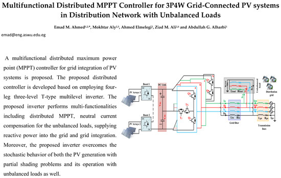
  • A new multifunctional distributed MPPT controller is proposed for integrating PV systems with distribution networks. The proposed inverter performs multifunctionalities including distributed MPPT, neutral current compensation for the existing unbalanced loads, and reactive power compensation.
  • The proposed controller is capable of injecting balanced sinusoidal currents with low output total harmonic distortion (THD) into the utility grid, regardless of the combined fluctuations of the PV generation and load demand.
  • An effective compensation method for the neutral currents is provided for four-wire distribution systems, which improves the energy efficiency and reliability of the whole distribution system and components.
The new proposed controller can provide a multifunctional operation of PV systems, while preserving simple implementation and lower number of components compared to [33], eliminating the need for precise modelling compared to the controllers in [29,30,31,32], and being suitable for low-cost microcontroller implementation. From another side, the new proposed system and controller can provide a more efficient and reliable power system operation through the achieved multifunctionalities of neutral current compensation, maximum energy extraction, and local reactive power supply.
The rest of the paper is organized as follows: Section 2 presents a detailed description of the 3P4W PV system. The modeling of various components in the 3P4W system is explained in detail in Section 3. The proposed controller and its implementation are provided in Section 4. Section 5 presents the simulation results and controller performance with different scenarios during PV partial shading and load unbalance. Finally, the paper is concluded in Section 6.

2. 3P4W Distribution System

2.1. Grid-Connected Four-Leg Inverter

Figure 1 shows a 3P4W grid-connected PV system using four-leg T-type multilevel inverter systems. The PV generation side is composed of PV panels, connected in series and parallel configuration. A DC-DC boost converter is employed by a MPPT for extracting the maximum power from PV panels. The DC-DC boost converter is followed by a DC-link capacitor, which is functioning as a decoupling stage between the PV system and the utility grid. The T-type inverter is employed in this manuscript for integrating the DC output voltage of the PV generation system into the utility grid. The L type filter is utilized as the filtering stage of the harmonics at the PV generation side. In addition, a fourth leg is included in the inverter for the neutral current compensation with the unbalanced loads. The selected case study employs unbalanced single-phase home loads at the output of the PV generation system. For simplicity, each PV panel is connected to an individual boost converter with individual MPPTs. However, the proposed system and analysis are valid for any number of individual PV systems. The selected case study contains double 7.5 kW PV generation system with a DC-DC boost converter, which corresponds to the total PV generation output power of 15 kW. The perturb and observe (P&O) MPPT method is selected for its simplicity and effectiveness [35]. The P&O MPPT method is integrated with the two boost converters for extracting the maximum available power from the PV modules. While this paper provides a real-time controller for 3P4W PV generation systems, the impacts of power systems are considered through modelling the grid impedance and considering the behavior of unbalanced single-phase loads.

2.2. Issues of PV Generation Side

The PV systems are sensitive to ambient conditions, such as atmospheric temperature, dust, and irradiance. The partial shading problem represents one of the main challenges to large-scale PV generation systems, wherein PV arrays are subjected to different irradiance levels. The current-voltage (I-V) and power-voltage (P-V) characteristics of PV systems with partial shading problems are shown in Figure 2 [36]. The presence of shadowed PV modules causes multi-peaks on the P-V curve, in which there is only one global peak. Defining the global peak MPPT of a shadowed PV system is tackled in several research articles. However, the developed techniques in the literature suffer from inaccurate MPPT, continuous search, low speed, and complex calculations [37]. Moreover, the power mismatches between series-connected PV modules represent another issue that decreases the output power of the PV systems. These mismatches may result from the losses in the array due to different specifications of PV modules and/or possessing different levels of irradiance by series-connected modules. The developed methods in [26] have not covered the partial shading problems of the PV generation systems at low voltage distribution network with the unbalanced loads.

2.3. Issues of Distribution Utility Side

The LV distribution network contains usually single-phase home loads, which are unbalanced loads and represent the main source for unbalanced operation in the three-phase distribution networks. These unbalanced single-phase loads cause the presence of neutral current in the utility grid. The presence of neutral current in LV distribution networks generates additional power losses, which increase the temperature of conductors and reduce the transmission line capacity. In addition, neutral currents may affect the operation of the power cables [38]. From the distribution transformer’s side, neutral currents cause their windings to overheat, energy losses to increase, and capacity, efficiency and lifetime to reduce [38]. In the 3P4L inverter system, the additional fourth leg is employed to achieve neutral current compensation and their corresponding zero sequence currents at the point of common coupling (PCC) [26]. The neutral current ILN, and zero sequence current IL0 in a 3P4W system are expressed as follows [39]:
I L N   =   I L a   +   I L b   + I L c
I L 0 = I L a +   I L b + I L c 3 =   I L N 3      
where ILa, ILb, ILc represent the three-phase load currents of a, b, and c phases respectively.

3. Modelling of Four-Leg PV-VSI System

3.1. Modeling of PV Generation Side

Figure 3 shows the equivalent model of a single PV cell. The electrical model contains the current source Iph with its parallel diode, series-connected resistance Rs, and shunt-connected resistance Rsh [40]. The series-connected resistance Rs denotes the losses due to the ohmic resistance, including semiconductor material resistance, metal contact, and resistance between contacts. Shunt-connected resistance Rsh denotes leakage currents of the junction through the edges of the PV cell. The mathematical relation relating voltage and current in the model of PV cell is constructed using the circuit model in Figure 3 and Kirchhoff’s laws [41]. In Figure 3, Ish and Id denote currents through shunt-connected resistance and the parallel diode, respectively. The dependence of the output current of the PV cell on ambient conditions is expressed as follows:
I p h = I p h , n ( K 1   ( T m T n ) )   ( G G n )
where Iph and Is denote the photocurrent of the PV cell and the saturation reverse current of diode, respectively, whereas Iph,n, Vtn, Gn represent the nominal parameters of the PV cell datasheet of photocurrent (A), the voltage (V), and nominal solar irradiance (equals to 1000 W/m2), respectively. K1 denotes the temperature coefficient of the cell short-circuit current (AK−1). Tm and Tn represent module temperature (°C), and nominal module temperature (equal to 25 °C), respectively. Moreover, VPV is denoting the PV cell output voltage. The output current of the PV module with Np parallel-connected PV cells is equal to the multiplying of IPV of a single cell with Np. The output voltage of the PV module with Ns series- PV cells is equal to multiplying VPV of a single cell with Ns.

3.2. Modeling of DC-DC Boost Converter

The main functionality of the DC-DC converter at the PV generation side is boosting the output voltage and extracting the MPPT of the PV system [42]. The boost converter is often employed at this stage as it has a continuous current at the PV side. Figure 4 shows the power circuit of the boost converter with the PV system at its input. The conversion ratio between input voltage VPV and output voltage Vo of the ideal boost converter is dependent on the duty cycle D of the power switch and the design of the inductor Lb and capacitor Cb with output load resistance Rof the boost converter [42]. The boost conversion ratio is calculated as follows [42]:
V o   =   1 ( 1 D ) V P V  

3.3. Modeling and Operation of T-Type Multilevel Inverter

A single-phase representation of the grid-connected T-type three-level inverter is shown in Figure 5 [43]. Each leg in the T-type inverter contains four power semiconductor switches (Sx1, Sx2, Sx3, Sx4, where x = a, b, or c phase). The three-level T-type inverter produces three levels of positive (P), negative (N) and zero (O) voltages. The P and N states are generated using the power switches Sx1 and Sx4, respectively. The positive current during these states flows through the switch, whereas the negative current passes through their freewheeling diodes. The output current passes through the switches at unity power factor and no current passes through the freewheeling diodes of switches Sx1 and Sx4. In addition, the bidirectional power switches Sx2 and Sx3 generate the zero voltage level of the inverter. The positive current passes through the switch Sx2 and the freewheeling diode of Sx3, however the negative current passes through the switch Sx3 and the freewheeling diode of Sx2.
Figure 6a shows the level-shift pulse width modulation (PWM) method for generating the gating pulses of three-level T-type inverter. For n number of levels, the level shift PWM requires (n − 1) carriers with levels shift. In each switching cycle Ts, the modulating signal Vmx is compared to the carrier signals and the corresponding gating pulses are produced. The output-phase voltage, current and the gating pulses of the switches are shown in Figure 6b,c, respectively. It is seen that the switch Sx1 is turned on in the positive half-cycle of Vmx, and the switch Sx4 is turned on in negative half-cycle, whereas the bidirectional switches Sx2 and Sx3 are gated for generating the zero level during the line period. The power switches Sx1 and Sx4 in T-type inverter are designed with full DC-link voltage rating, whereas the switches Sx2 and Sx3 are designed with half DC-link voltage rating.

3.4. Modeling of Distribution Network Side.

A single-phase representation of the four-wire distribution system with L filter is shown in Figure 7. The generated power and current of the PV system are transferred into AC power using the inverter system according to the modulation command dx of the inverter. The L filter and the transmission line are modeled using inductances (Lf, Lg) and series resistances (Rf, Rg), respectively, whereas the neutral filter and the neutral conductor are modeled using (Lfn, Lgn) for inductances and (Rfn, Rgn) for resistances, respectively [26].
The averaged single-phase model of the four-wire system shown in Figure 7 is represented as follows:
L f d d t I f x =   V d c d i x R f I f x V P C C x + L f n d d t I f n + R f n I f n
L g d d t I g x =   V P C C x R g I g x V g x + L g n d d t I g n + R g n I g n
I g = I f x I L x
C d c d d t V d c =   I p v I d c = I p v   d i x d i x
where the currents of three phase system for x phase (x = a, b, or c) are represented with I f x = [ I f a I f b I f c ] T , I g x = [ I g a I g b I g c ] T , V P C C x = [ V P C C a V P C C b V P C C c ] T , V g x = [ V g a V g b V g c ] T , and d i x = [ d i a k i b k i c ] T .

4. The Proposed Controller for 3P4W System

4.1. The Proposed System

The main functionality of the proposed controller is extracting the peak available output power from the PV panels. This is done by adding an individual boost type DC-DC converter with each PV panel, where the boost converter is responsible for achieving MPPT control. In addition, the proposed PV system employs a three-phase T-type multilevel inverter with additional fourth leg neutral current compensation. The T-type PV inverter feeds the energy to the unbalanced loads and the AC utility grid through the L filter circuit. The 3P4W T-type multilevel inverter with an additional fourth leg is utilized to compensate the zero sequence currents due to the unbalanced distribution load at the point of common-coupling (PCC), which can noticeably reduce overloading and power losses of the neutral conductors. Figure 8 shows the complete proposed system and controller for the 3P4W PV system. For simplicity, the PV system is considered equally divided on two boost converters; however, the proposed system can be adapted to any number of series PV modules. The proposed controller will be divided into two main parts: the distributed MPPT algorithm, and the grid-connected inverter control. The main operation and structure of each part is explained in the following subsections.

4.2. The Distributed MPPT Algorithm

The proposed distributed MPPT system is based on employing the widely used perturb and observe (P&O) MPPT algorithm [44]. The flowchart implementation of the P&O MPPT algorithm is shown in Figure 9, wherein the calculation of PV output power varies according to the output voltage and current of the PV array. The P&O technique for MPPT employs the measured current and voltage of each PV array to perturb the converter duty cycle and observe the measured quantities to track the MPP of the PV system. The duty cycle of the boost DC-DC converter is perturbed positively or negatively according to the increase/decrease of the PV terminal voltage and output power. At the beginning of each switching cycle, the dP/dV slope is obtained, and the increase/decrease operation is defined. If the slope dP/dV > 0, the converter is directed towards the maximum operating power and the converter continues to perturb the PV array voltage in the same direction. On the other hand, if the slope dP/dV < 0, the change in the voltage point and actual power point of PV array moves far from the MPP, and the P&O algorithm changes the direction of the perturbation.
For the proposed distributed MPPT controller, each PV array possesses an individual MPPT algorithm. Therefore, mismatched losses in MPPTs due to the partial shading between the PV modules are mitigated. According to the PV systems configurations, the distributed MPPT control can be realized to extend the multistring of the DC-DC converter.

4.3. The Grid-Connected Inverter Control

The grid-tied PV inverter is employed for injecting the generated solar power into the utility grid. The d-q synchronous reference frame control method is used for implementing the PV inverter controller. The active power control is achieved through controlling the DC link voltage of the inverter, whereas the reactive current control is performed using the AC voltage control of the PCC. Firstly, the measured voltages and currents at the PCC are transformed from the a-b-c reference frame into the d-q reference frame. The synchronization process of the proposed controller is achieved by using the phase locked loop (PLL) system. The details of the design method for the PV inverter controller can be found in [45]. Entirely, the d-q control method consists of two control loops: the d-axis control loop, and the q-axis control loop.
In the proposed control system shown in Figure 8, the output voltage and current of each PV array are sensed and fed to the individual MPPT algorithm, which is functioning to control the duty cycles of the adjacent boost DC-DC converter according to the required maximum power point operation. The demanded duty cycles of each power converter are transferred into gating pulses to the power switches through the pulse width modulation (PWM) block. The multilevel T-type inverter is synchronized with the utility distribution grid by employing the angle θ, which is generated using the inverter PLL block. The decoupled d-q current controller is employed in the proposed controller for controlling the injected active and reactive power from the PV inverter. The load currents are utilized in the proposed controller for generating the reference current for the fourth leg of the inverter. Moreover, an additional separate zero-sequence compensation loop is used in the proposed controller for enhancing the performance of the system. Finally, the generated modulation signals are compared with the carrier signals in the sinusoidal PWM to generate the gating pulses for the switches in the inverter leg as in [46].

5. Results and Discussion

The proposed system and controller parameters for the case study are shown in Table 1. The proposed distributed MPPT and grid-connected 3P4W T-type PV inverter based on four-wire distribution networks with unbalanced loads is implemented and simulated in the PSIM environment. The total PV system is 15 kW PV system. It is divided into two 7.5 kW PV arrays with two individual boost DC-DC converters. Each PV array consists of 5 modules in series and 6 modules in parallel from the selected PV panel model SUNTECH STP250S-20/Wd. The inverter is operated with 10 kHz switching frequency in the selected case study.

5.1. Performance Evaluation of the Proposed Controller

5.1.1. Single Array Partial Shading

The proposed inverter and controller are tested with the case of partial shading of a single PV array, keeping the irradiance on the first array constant at 1000 W/m2. The irradiance of the second array is shaded at 500 W/m2 at time 0.4 s as shown in Figure 10. It is clear from Figure 10a that the proposed controller is capable of extracting the MPPT of each PV array even if there is a mismatch in their individual irradiance levels. The non-shaded PV array is operated at its maximum power of 7.5 kW, whereas the shaded PV array is operating at its maximum power of 3.75 kW that corresponds to 500 W/m2 irradiance. Moreover, the proposed distributed MPPT method is capable of harvesting the maximum power of the PV arrays, regardless of the load condition of balanced or unbalanced cases. The result confirms the improved MPPT efficiency of the new proposed controller at partial shading conditions. Therefore, the levelized cost of energy (LCOE) of PV systems is improved through the new proposed controller.
From another side, Figure 10b shows the output currents of the PV inverter (Ia, Ib, Ic), grid injected/absorbed currents (Iga, Igb, Igc), load currents (ILa, ILb, ILc), and neutral conductor currents (Ign, Ifn, ILN). The selected case study is tested at balanced and unbalanced load scenarios as listed in Table 1, wherein the load unbalance occurs at time 0.75 s. It is seen that the proposed system and controller preserve sinusoidal output currents with compensating the load unbalance. The fourth leg of the inverter injects zero current at a balanced load scenario, whereas the proposed inverter injects neutral current at the point of common coupling through the fourth leg with an equal magnitude and opposite direction to the neutral wire of the load. Therefore, the absorbed neutral current from the distribution grid equals to zero, which leads to improving the efficiency of the distribution system. Moreover, the cost of the neutral conductor can be reduced through the use of conductors with smaller cross-sectional area.
In addition, the proposed controller can extract the individual MPPT of each PV array using the DC-DC boost converters and inject it with balanced output currents to the utility grid at both scenarios of balanced and unbalanced load conditions. Figure 10c shows the total harmonic distortion (THDs) analysis of the inverter currents (Ia, Ib, Ic) for the selected case study at balanced and unbalanced load conditions. It is seen that the THD components represent 1.27% during the period from 0.2 to 0.4 s at a balanced load scenario, whereas the THD of the inverter currents at unbalanced loads during the time period from 1.1 to 1.2 s is 1.29%. The THD of the output currents is preserved under the specified limits by the grid codes using the proposed controller at balanced and unbalanced load conditions as well. Therefore, the superiority of the proposed system and controller has become clear at achieving distributed MPPT of PV systems with compensating the load unbalance while injecting high-quality currents into the utility grid.

5.1.2. Two Arrays Partial Shading

The proposed controller is also tested using the selected case study with partial shading on the two arrays at the same time, wherein the upper and lower PV arrays are operated at 500 W/m2. Figure 11a shows the simulation results of the output power of the PV arrays, and the total output PV power. It is seen that the proposed controller has the ability to extract the MPPT of each PV array at normal and partial shading conditions. Both of the PV arrays are operated at their maximum power of 3.75 kW at 500 W/m2 solar irradiance level, whereas each PV generates an output power of 7.5 kW at 1000 W/m2 irradiance.
Figure 11b shows the current waveforms of the PV inverter, grid side, load side, and neutral conductors. It is seen that the proposed controller is capable of balancing the load through injecting current from the fourth leg that is equal in magnitude and opposite in direction to the neutral current. Hence, the proposed controller eliminates the absorbed neutral current from the distribution grid. In addition, the proposed system and controller injects sinusoidal currents into the utility grid, regardless of the unbalanced load. Figure 11c shows the THDs spectrum of inverter output currents (Ia, Ib, Ic) at balanced and unbalanced load conditions. It is seen that the THD is 1.30% at balanced load condition, whereas the THD is 1.31% at unbalanced load condition. Therefore, the proposed controller preserves the THD components under the specified limits of the grid-connected PV system. It is concluded that the proposed controller can successfully extract the individual MPPT of each PV array, inject balanced output currents to the utility grid and compensate the neutral current in the 3P4W distribution system.

5.2. Performance Comparison

The performance of the proposed distributed MPPT controller with four-wire distribution systems is compared with the other conventional methods in the literature. The central MPPT method is selected as a case study for the comparison, wherein a single boost DC-DC converter is employed for MPPT extraction. The simulation results of the central MPPT controller under balanced and unbalanced load scenarios are shown in Figure 12. In the selected case study, only the lower array is shaded at 500 W/m2, whereas the upper PV array is kept at 1000 W/m2. The extracted PV output power of both arrays and the total output power are shown in Figure 12a. It is seen that the conventional controller fails in extracting the maximum power from the upper array, and the performance of the PV system is limited by the array with the lowest irradiance level. The unshaded PV array outputs only 4500 W under the conventional MPPT method, whereas the proposed controller outputs 7.5 kW at the same condition. Hence, the conventional MPPT method can extract only about 8.1 kW, which is lower than the 11.25 kW with the proposed controller. From another side, the conventional control method can achieve sinusoidal current injection into the utility grid as shown in Figure 12b. Moreover, the fourth inverter leg can achieve neutral current compensation with the unbalanced load condition. Figure 12c shows the THD components of the inverter output currents under the conventional control method. It is seen that the THD is under the defined limits by the utility grids at both balanced and unbalanced load scenarios. However, the conventional control method fails to keep the maximum power point of the PV system. Hence, deterioration of the output power is caused by the conventional control method.

5.3. Energy Efficiency Comparison

The performance of the proposed controller and the conventional central MPPT method is compared in Figure 13. The two PV systems are compared with single array partial shading at various shading levels. The irradiation level on the lower PV array is varied, whereas the irradiance of the upper PV array is kept constant at 1000 W/m2. As shown in the previous analysis, the proposed controller is capable of extracting individual MPPT of each of the PV arrays, whereas the conventional controller limits the output power according to the shaded array level. The result in Figure 13 shows that effective performance can be achieved using the proposed controller in comparison to the conventional one. The energy efficiency of the proposed controller increases proportionally with increased shading levels compared to the conventional one. It is seen that the proposed controller enables each PV array to operate at MPPT, while the conventional controller is incapable of achieving individual MPPT of the PV arrays. The superiority of the proposed controller becomes clear with regard to achieving individual MPPT, injecting sinusoidal currents into the utility grid, compensating neutral current of the unbalanced load, and achieving a high-power quality PV grid-tied system.

6. Conclusions

A multifunctional four-leg three-level T-type inverter system and controller are presented in this paper for enhancing the performance of grid-connected PV systems in distribution networks. The proposed system and controller possess several enhanced performance criteria for PV system integration with unbalanced loads. The proposed controller is capable of injecting high-power quality sinusoidal currents from the PV system. Moreover, the proposed controller achieves distributed MPPT under various conditions of irradiation and unbalanced load current scenarios. The performance of the proposed controller is tested using a 15 kW PV generation system at various fluctuating PV generation and unbalanced load demand conditions. In addition, a performance comparison with the conventional central MPPT methods is provided. The proposed controller achieves advantageous MPPT of the PV system compared to conventional central MPPT architecture, especially at scenarios of high shading levels. The enhanced performance of the proposed controller is verified in the paper regarding the high-energy efficiency, low THD components and load unbalance compensation. The results also show the success of the proposed systems and controller in completely compensating the neutral currents. Moreover, the THD of the injected current into the utility grid by the new proposed controller is kept under 1.31% for all the tested scenarios.

Author Contributions

Conceptualization, E.M.A.; M.A.; A.E.; Methodology, E.M.A.; M.A.; Software, M.A.; Z.M.A.; Validation, E.M.A.; Z.M.A.; A.G.A.; Formal Analysis, E.M.A. and M.A.; Investigation, A.E.; Resources, Z.M.A. and A.G.A.; Data Curation, A.E.; Writing—Original Draft Preparation, A.E.; Writing—Review & Editing, E.M.A. and M.A.; Visualization, A.E.; Supervision, E.M.A; M.A.; Funding Acquisition, A.G.A. All authors have read and agreed to the published version of the manuscript.

Funding

This work is supported by the research project No. 324/40, sponsored by the Deanship of Scientific Research at Jouf University, Aljouf, Saudi Arabia.

Conflicts of Interest

The authors declare no conflict of interest.

Abbreviations

The following abbreviations are used in this manuscript:
3P4WThree-phase four-wire distribution system
MPPTMaximum Power Point Tracking
THDTotal Harmonic Distortion
DMPPTDistributed Maximum Power Point Tracking
PCCPoint of Common Coupling
PLLPhase Locked Loop

References

  1. Balathandayuthapani, S.; Edrington, C.S.; Henry, S.D.; Cao, J. Analysis and control of a photovoltaic system: Application to a high-penetration case study. IEEE Syst. J. 2012, 6, 213–219. [Google Scholar] [CrossRef]
  2. Yang, Y.; Yeh, H.-G.; Doan, S. Optimal control methods for photovoltaic enabled grid with abnormal power loads. IEEE Syst. J. 2019, 1–10. [Google Scholar] [CrossRef]
  3. Elmelegi, A.; Aly, M.; Ahmed, E.M. Developing Phase-Shift PWM-Based Distributed MPPT Technique for Photovoltaic Systems. In Proceedings of the 2019 International Conference on Innovative Trends in Computer Engineering (ITCE), Aswan, Egypt, 2–4 February 2019; pp. 492–497. [Google Scholar]
  4. Aly, M.; Ahmed, E.; Shoyama, M. A new single phase five-level inverter topology for single and multiple switches fault tolerance. IEEE Trans. Power Electron. 2018, 33, 9198–9208. [Google Scholar] [CrossRef]
  5. Baghaee, H.R.; Mirsalim, M.; Gharehpetian, G.B. Performance improvement of multi-DER microgrid for small- and large-signal disturbances and nonlinear loads: Novel complementary control loop and fuzzy controller in a hierarchical droop-based control scheme. IEEE Syst. J. 2018, 12, 444–451. [Google Scholar] [CrossRef]
  6. Priyadarshi, N.; Padmanaban, S.; Kiran Maroti, P.; Sharma, A. An extensive practical investigation of FPSO-based MPPT for grid integrated PV system under variable operating conditions with anti-islanding protection. IEEE Syst. J. 2018, 1–11. [Google Scholar] [CrossRef] [Green Version]
  7. Mirzaei, M.A.; Yazdankhah, A.S.; Mohammadi-Ivatloo, B.; Marzband, M.; Shafie-khah, M.; Catalão, J.P.S. Stochastic network-constrained co-optimization of energy and reserve products in renewable energy integrated power and gas networks with energy storage system. J. Clean. Prod. 2019, 223, 747–758. [Google Scholar] [CrossRef] [Green Version]
  8. Sagha, H.; Mokhtari, G.; Arefi, A.; Nourbakhsh, G.; Ledwich, G.; Ghosh, A. A new approach to improve PV power injection in LV electrical systems using DVR. IEEE Syst. J. 2018, 12, 3324–3333. [Google Scholar] [CrossRef]
  9. Marzband, M.; Azarinejadian, F.; Savaghebi, M.; Pouresmaeil, E.; Guerrero, J.M.; Lightbody, G. Smart transactive energy framework in grid-connected multiple home microgrids under independent and coalition operations. Renew. Energy 2018, 126, 95–106. [Google Scholar] [CrossRef]
  10. Valinejad, J.; Barforoshi, T.; Marzband, M.; Pouresmaeil, E.; Godina, R.; Catalão, J.P.S. Investment Incentives in Competitive Electricity Markets. Appl. Sci. 2018, 8, 1978. [Google Scholar] [CrossRef] [Green Version]
  11. Monfared, H.J.; Ghasemi, A.; Loni, A.; Marzband, M. A hybrid price-based demand response program for the residential micro-grid. Energy 2019, 185, 274–285. [Google Scholar] [CrossRef]
  12. Chen, K.; Tian, S.; Cheng, Y.; Bai, L. An improved MPPT controller for photovoltaic system under partial shading condition. IEEE Trans. Sustain. Energy 2014, 5, 978–985. [Google Scholar] [CrossRef]
  13. Kofinas, P.; Doltsinis, S.; Dounis, A.I.; Vouros, G.A. A reinforcement learning approach for MPPT control method of photovoltaic sources. Renew. Energy 2017, 108, 461–473. [Google Scholar] [CrossRef]
  14. Kumar, N.; Saha, T.K.; Dey, J. Multilevel inverter (MLI)-based stand-alone photovoltaic system: Modeling, analysis, and control. IEEE Syst. J. 2019, 1–7. [Google Scholar] [CrossRef]
  15. Eshwar Gowd, G.; Sekhar, P.C.; Sreenivasarao, D. Real-time validation of a sliding mode controller for closed-loop operation of reduced switch count multilevel inverters. IEEE Syst. J. 2019, 13, 1042–1051. [Google Scholar] [CrossRef]
  16. Aly, M.; Ahmed, E.M.; Shoyama, M. Thermal stresses relief carrier-based PWM strategy for single phase multilevel inverters. IEEE Trans. Power Electron. 2017, 32, 9376–9388. [Google Scholar] [CrossRef]
  17. Cherian, E.; Bindu, G.R.; Chandramohanan Nair, P.S. Pollution impact of residential loads on distribution system and prospects of DC distribution. Eng. Sci. Technol. Int. J. 2016, 19, 1655–1660. [Google Scholar] [CrossRef] [Green Version]
  18. Sreenivasarao, D.; Agarwal, P.; Das, B. Neutral current compensation in three-phase, four-wire systems: A review. Electr. Power Syst. Res. 2012, 86, 170–180. [Google Scholar] [CrossRef]
  19. Vechiu, I.; Curea, O.; Camblong, H. Transient operation of a four-leg inverter for autonomous applications with unbalanced load. IEEE Trans. Power Electron. 2010, 25, 399–407. [Google Scholar] [CrossRef]
  20. Gruzs, T.M. A survey of neutral currents in three-phase computer power systems. IEEE Trans. Ind. Appl. 1990, 26, 719–725. [Google Scholar] [CrossRef]
  21. Nassif, A.B.; Xu, W.; Freitas, W. An investigation on the selection of filter topologies for passive filter applications. IEEE Trans. Power Deliv. 2009, 24, 1710–1718. [Google Scholar] [CrossRef]
  22. Vodyakho, O.; Mi, C.C. Three-level inverter-based shunt active power filter in three-phase three-wire and four-wire systems. IEEE Trans. Power Electron. 2009, 24, 1350–1363. [Google Scholar] [CrossRef]
  23. Pattnaik, M.; Kastha, D. Harmonic compensation with zero-sequence load voltage control in a speed-sensorless DFIG-based stand-alone VSCF generating system. IEEE Trans. Ind. Electron. 2013, 60, 5506–5514. [Google Scholar] [CrossRef]
  24. Wu, J.-C.; Jou, H.-L.; Wu, K.-D.; Xiao, S.-T. Single-phase inverter-based neutral-current suppressor for attenuating neutral current of three-phase four-wire distribution power system. IET Gener. Transm. Distrib. 2012, 6, 577–583. [Google Scholar] [CrossRef]
  25. Singh, M.; Khadkikar, V.; Chandra, A.; Varma, R.K. Grid interconnection of renewable energy sources at the distribution level with power-quality improvement features. IEEE Trans. Power Deliv. 2011, 26, 307–315. [Google Scholar] [CrossRef]
  26. Rafi, F.H.M.; Hossain, M.J.; Lu, J. Improved neutral current compensation with a four-leg PV smart VSI in a LV residential network. IEEE Trans. Power Deliv. 2017, 32, 2291–2302. [Google Scholar] [CrossRef]
  27. Wang, X.; Zhuo, F.; Li, J.; Wang, L.; Ni, S. Modeling and control of dual-stage high-power multifunctional PV system in d–q–o Coordinate. IEEE Trans. Ind. Electron. 2013, 60, 1556–1570. [Google Scholar] [CrossRef]
  28. Kabir, M.N.; Mishra, Y.; Ledwich, G.; Dong, Z.Y.; Wong, K.P. Coordinated control of grid-connected photovoltaic reactive power and battery energy storage systems to improve the voltage profile of a residential distribution feeder. IEEE Trans. Ind. Inform. 2014, 10, 967–977. [Google Scholar] [CrossRef]
  29. Bayhan, S.; Trabelsi, M.; Abu-Rub, H.; Malinowski, M. Finite-control-set model-predictive control for a quasi-Z-source four-leg inverter under unbalanced load condition. IEEE Trans. Ind. Electron. 2017, 64, 2560–2569. [Google Scholar] [CrossRef]
  30. Yaramasu, V.; Rivera, M.; Narimani, M.; Wu, B.; Rodriguez, J. Model predictive approach for a simple and effective load voltage control of four-leg inverter with an output LC filter. IEEE Trans. Ind. Electron. 2014, 61, 5259–5270. [Google Scholar] [CrossRef]
  31. Chen, Q.; Luo, X.; Zhang, L.; Quan, S. Model predictive control for three-phase four-leg grid-tied inverters. IEEE Access 2017, 5, 2834–2841. [Google Scholar] [CrossRef]
  32. Bayhan, S.; Abu-Rub, H.; Balog, R.S. Model predictive control of quasi-Z-source four-leg inverter. IEEE Trans. Ind. Electron. 2016, 63, 4506–4516. [Google Scholar] [CrossRef]
  33. Mello, J.P.R.A.; Jacobina, C.B.; de Rossiter Correa, M.B. Three-phase four-wire inverters based on cascaded three-phase converters with four and three legs. IEEE Trans. Ind. Appl. 2017, 53, 5539–5552. [Google Scholar] [CrossRef]
  34. Rojas, F.; Kennel, R.; Cardenas, R.; Repenning, R.; Clare, J.C.; Diaz, M. A new space-vector-modulation algorithm for a three-level four-leg NPC inverter. IEEE Trans. Energy Convers. 2017, 32, 23–35. [Google Scholar] [CrossRef]
  35. Hussein, K.H. Maximum photovoltaic power tracking: An algorithm for rapidly changing atmospheric conditions. IEE Proc. Gener. Transm. Distrib. 1995, 142, 59–64. [Google Scholar] [CrossRef]
  36. Dileep, G.; Singh, S.N. An improved particle swarm optimization based maximum power point tracking algorithm for PV system operating under partial shading conditions. Sol. Energy 2017, 158, 1006–1015. [Google Scholar] [CrossRef]
  37. Mahmoud, Y.; El-Saadany, E.F. Enhanced reconfiguration method for reducing mismatch losses in PV systems. IEEE J. Photovolt. 2017, 7, 1746–1754. [Google Scholar] [CrossRef]
  38. Tofoli, F.L.; Sanhueza, S.M.R.; deOliveira, A. On the Study of Losses in Cables and Transformers in nonsinusoidal conditions. IEEE Trans. Power Deliv. 2006, 21, 971–978. [Google Scholar] [CrossRef]
  39. Md Rafi, F.H.; Hossain, M.J.; Rahman, M.S.; Lu, J. Impact of controlling zero sequence current in a three-phase four-wire LV network with PV units. In Proceedings of the 2016 IEEE Power and Energy Society General Meeting (PESGM), Boston, MA, USA, 17–21 July 2016; pp. 1–5. [Google Scholar]
  40. Patel, H.; Agarwal, V. MATLAB-based modeling to study the effects of partial shading on PV array characteristics. IEEE Trans. Energy Convers. 2008, 23, 302–310. [Google Scholar] [CrossRef]
  41. Elmelegi, A.; Aly, M.; Ahmed, E.M.; Alharbi, A.G. A simplified phase-shift PWM-based feedforward distributed MPPT method for grid-connected cascaded PV inverters. Sol. Energy 2019, 187, 1–12. [Google Scholar] [CrossRef]
  42. Roman, E.; Alonso, R.; Ibanez, P.; Elorduizapatarietxe, S.; Goitia, D. Intelligent PV Module for Grid-Connected PV Systems. IEEE Trans. Ind. Electron. 2006, 53, 1066–1073. [Google Scholar] [CrossRef]
  43. Aly, M.; Dousoky, G.M.; Shoyama, M. Design and Validation of SVPWM Algorithm for Thermal Protection of T-Type Three-Level Inverters. In Proceedings of the 2015 IEEE International Telecommunications Energy Conference (INTELEC), Osaka, Japan, 18–22 October 2015; pp. 1074–1079. [Google Scholar]
  44. Esram, T.; Chapman, P.L. Comparison of photovoltaic array maximum power point tracking techniques. IEEE Trans. Energy Convers. 2007, 22, 439–449. [Google Scholar] [CrossRef] [Green Version]
  45. Teodorescu, R.; Liserre, M.; Rodriguez, P. Grid Converters for Photovoltaic and Wind Power Systems; IEEE Wiley: Piscataway, NJ, USA; Chichester, UK; Hoboken, NJ, USA, 2011; ISBN 978-0-470-05751-3. [Google Scholar]
  46. Ramadan, D.; Aly, M.; Ahmed, E.M. Practical performance analysis and device selection for photovoltaic multilevel inverters installations. In Proceedings of the 2019 International Conference on Innovative Trends in Computer Engineering (ITCE), Aswan, Egypt, 2–4 February 2019; pp. 559–563. [Google Scholar]
Figure 1. Power circuit of the proposed three-phase four-wire (3P4W) grid-connected photovoltaic (PV) system.
Energies 12 04799 g001
Figure 2. Current-voltage (I-V) and power-voltage (P-V) characteristics of the PV array with partial shading.
Energies 12 04799 g002
Figure 3. The electrical equivalent circuit model of single PV cell.
Energies 12 04799 g003
Figure 4. Power circuit diagram of an ideal boost DC-DC converter.
Energies 12 04799 g004
Figure 5. Single-phase representation of grid-connected T-type PV inverter.
Energies 12 04799 g005
Figure 6. Level shift modulation and its corresponding gating pulses of the three-level T-type inverter.
Energies 12 04799 g006aEnergies 12 04799 g006b
Figure 7. The averaged single-phase equivalent model of the four-wire system.
Energies 12 04799 g007
Figure 8. Control block diagram of designed four-leg T-type multilevel inverter with LV distribution network grid-connected PV system.
Energies 12 04799 g008
Figure 9. Perturb and observe (P&O) maximum power point tracking (MPPT) method for the proposed 3P4W system.
Energies 12 04799 g009
Figure 10. The simulation results of proposed control performance with single array partial shading.
Energies 12 04799 g010aEnergies 12 04799 g010b
Figure 11. The simulation results of proposed control performance with two arrays partial shading.
Energies 12 04799 g011
Figure 12. The simulation results of the conventional central MPPT performance with single array partial shading.
Energies 12 04799 g012aEnergies 12 04799 g012b
Figure 13. Comparison of the total output power between the proposed distributed MPPT method and the conventional central MPPT method with single array partial shading.
Energies 12 04799 g013
Table 1. System parameters for the selected case study.
ParametersValues
Capacitor of DC-link3000 μF
DC-link bus voltage615 V
Filter inductor Lf7 mH
Resistance of filter inductor Rf0.5 Ω
Grid rms voltage Vgrid220 V
Grid line frequency Fl50 Hz
Transmission lines parameters L, R7 mH, 0.05 Ω
Distribution system grounding resistance RGND10 Ω
Switching frequency of the inverter Fsw10 kHz
Input inductance of boost converters0.5284 mH
Output capacitor of boost converters13.232 μF
Balanced loadsLoad a, b, c resistance10 Ω, 10 Ω, 10 Ω
Load a, b, c inductance500 mH, 500 mH, 500 mH
Unbalanced loadsLoad a, b, c resistance10 Ω, 10 Ω, 5 Ω
Load a, b, c inductance500 mH, 500 mH, 250 mH

