Article

Overcharge Cycling Effect on the Surface Layers and Crystalline Structure of LiFePO4 Cathodes of Li-Ion Batteries

by
Evgenii V. Beletskii
1,
Elena V. Alekseeva
1,
Dar’ya V. Spiridonova
2,
Andrei N. Yankin
3 and
Oleg V. Levin
1,*
1
Institute of Chemistry, St. Petersburg State University, St. Petersburg 199034, Russia
2
Research Park, St. Petersburg State University, St. Petersburg 199034, Russia
3
Department of Nanophotonics and Metamaterials, ITMO University, St. Petersburg 197101, Russia
*
Author to whom correspondence should be addressed.
Energies 2019, 12(24), 4652; https://doi.org/10.3390/en12244652
Submission received: 5 November 2019 / Revised: 2 December 2019 / Accepted: 4 December 2019 / Published: 7 December 2019
(This article belongs to the Section D1: Advanced Energy Materials)

Abstract

:
Electrochemical cells using LiFePO4 cathode material are considered one of the safest and most resistant to overcharging among Li-ion batteries. However, if LiFePO4-based electrodes are exposed to high potentials, surface and structural changes may occur in the electrode material. In this study Li/LiFePO4 half-cells were overcharged under different modes with variable cut-off voltages and charge currents. The change in voltage profile, discharge capacity, surface layers composition, and crystalline structure were characterized after overcharge cycles. It was demonstrated that the cathode material is resistant to short-term overcharging up to 5 V, but undergoes irreversible changes with increasing overcharge time or potential. Thus, despite the well-known tolerance of LiFePO4-based batteries to overcharge, a long overcharge time or high cut-off voltage leads to destructive changes in the cathode and should be avoided.

1. Introduction

Lithium-ion batteries (LIB) and electrochemical capacitors (EC) are currently the most important energy storage devices. EC have high power density and can sustain thousands of charge/discharge cycles [1,2,3]. However, the high energy and power density of LIB made them a preferable power source for electronic devices and electrical vehicles (EV). Despite the existence of various breakthrough technologies in both LIB [4,5,6,7] and EC [8,9] areas, commercially available lithium-ion batteries are currently based on traditional “high-voltage” materials, such as LiCoO2 and LiNi1−x−yCoxMnyO2, and “low-voltage” material LiFePO4 [10,11,12,13]. LiCoO2 (LCO), developed by Goodenough [5], is the first and most commercially successful example of cathode material based on layered transition metal oxides. This material was commercialized by SONY back in 1991 and still is the most common material for the cathodes of lithium-ion batteries, as it has a relatively large theoretical capacity (274 mAh·g−1), high theoretical volumetric capacity (1363 mAh·cm−3), high discharge voltage and good stability [14]. However, this material also has some fundamental shortcomings—a high price, low thermal stability, and the impossibility of a full charge to the theoretical capacity due to the destruction of the crystal structure at high cell voltages [15,16,17]. Another cathode material, nickel rich-layered oxide LiNi1−x−yCoxMnyO2 has a high specific capacity, but due to the high discharge voltage, its stability and safety still require substantial improvement [10,18,19,20,21]. The structural changes were detected in the anode and the cathode of the overcharged cells, indicating migration of the transition metals to the anode, loss of electrodes integrity, and irreversible Li loss from the cathode [22,23,24,25]. As a result, the market share of the low-voltage cathode material LiFePO4 (LFP) is currently growing [11,26,27,28]. Low cost, high thermal stability, non-toxicity, and the safety of this material makes it promising for various types of LIB [18,29]. Although, the plateau of the discharge voltage (3.4 V vs. Li+/Li) of this material is lower than that of LiCoO2, the discharge voltage is very stable and is located in the electrochemical stability window of the existing commercially available electrolyte system, preventing electrolyte decomposition on the charged cathode and ensuring the absence of the formation of the solid electrolyte interface layer (SEI). The stability of LFP itself results from the olivine structure and the stable P-O bonds [30,31]. This allows positioning LFP as the safest and most resistant to overcharge electrode material [32]. LFP has a wide application in areas where a stable and safe storage of significant amounts of energy is required, such as in hybrid electric vehicles. LFP is characterized by low diffusion coefficient of lithium ions, low electron conductivity, and as a consequence, lower specific discharge power of the material, which limits its application. Several strategies have been proposed to improve the energy storage properties of the material, of which, the commercially successful were particle size reduction, carbon coating, and doping [33]. Although, electrodes based on stable low voltage cathode materials, such as LiFePO4 are considered stable during overcharging [12,13,15,16], the small size of LiFePO4 nanoparticles increase the surface area of the material. As a result of adverse reactions during charge and discharge can lead to the formation of SEI, a layer with a complex composition and morphology, at the contact boundary of electrode materials and electrolyte [10]. On carbonaceous anodes, SEI is a necessary component of the normal operation of a lithium-ion battery. It provides passivation of the anode, preventing further decomposition of the electrolyte. The formation of SEI on cathode materials occurs at sufficiently high potentials and is critical when the nominal charge voltage of the electrodes is exceeded [10]. In such cases, thick layers of decomposition products are formed on the surfaces both of the cathode and anode materials. It leads to increase in the internal resistance, decrease of lithium diffusion rate, and significant LIB performance degradation [10,11]. The abuse of operation produces a local heating (>200 °C), resulting in cell destruction with possible ignition. Only the Li-ion batteries based on lithium iron phosphate/titanate (LiFePO4/Li4Ti5O12) are considered highly secure [32]. Despite the complicated nature of processes leading to battery degradation, overcharge tests of LFP cells were focused mostly on integrity and thermal behavior of the commercial or custom large full cells with graphite [12,34,35,36,37] or Li4Ti5O12 anodes.
In the studies focused on the deeper investigation of the failure mechanism of LiFePO4 cells during overcharge conditions, authors control the overcharge by the fixed state of charge of the full cell, which gives less possibility to control the cathode potential. For example, in LFP/graphite 18,650 cell, charged up to 5.5 V, cathode potential hardly reaches 5 V [12]. All of the described experiments were accompanied by dominant anodic adverse processes and temperature increase in the initial stage of cell thermal runaway. The cells with polymer electrolyte adverse processes appear at even lower cell potentials, and the cell voltage did not exceed 4.4 V [38]. It means that cathode voltage and temperature are not fully controlled during such type of overcharge tests, thereby introducing uncertainties into the origin of observed changes in the cathode material and imposing restrictions in using the obtained results for other types of cells and charge patterns. Therefore, despite the examples on the effect of overcharge of LiFePO4 already reported elsewhere, we could not find any appropriate data on the LiFePO4 surface and crystalline structure changes at low-temperature overcharge with controlled cut-off potential and rate in the literature.
In this work we performed charge-discharge tests of LiFePO4-based half-cells at various overcharge modes, different by cut-off potential and overcharge rate. X-ray photoelectron spectroscopy (XPS) and X-ray diffraction (XRD) study of overcharged LiFePO4 cathodes allowed detecting surface and structural changes of the material, caused by the overcharge potential. The results showed that this material is resistant to short-term overcharging up to 5 V, but undergoes irreversible changes with increasing overcharge time or potential.

2. Materials and Methods

Electrode preparation. A slurry of 80% LiFePO4 (Enam Optoelectronic Material Co., Ltd., Changsha China, typical particle size 200 nm), 10% carbon black Super-P (Alfa Aesar, Tewksbury, USA), and 10% polyvinylidene difluoride (PVDF) (Solef® 6010, Solvay, Brussels, Belgium ) was prepared by mixing the calculated amounts of the components in N-methylpyrrolidone (Vecton, St. Peterburg, Russia) for 10 min at a speed of 10,000 rpm using the FSH-2A homogenizer (Ningbo Hinotek Instriment Co., Ningbo Hi-Tech Zone, Ningbo, China). Then slurry was cast onto aluminum foil (22 µm, MTI Corp., New York, NY, USA) using the Doctor Blade applicator with the gap adjusted to obtain a coating density of about 5.7–8.6 mg cm−2 (0.8–1.2 mAh·cm−2). The electrodes were dried in a vacuum at a temperature of 80 °C for 24 h. After drying, the electrodes were compressed by roll press. The final thickness of the electrode with foil was 60 µm.
Coin cell assembly. The electrodes were cut out by 16 mm disc cutter and put in CR 2032 type cases inside a glove box filled with argon (<1 ppm H2O) according to the standard procedure. The electrolyte is 1 mol dm−3 LiPF6 in 1:1 ethylene carbonate: diethyl carbonate (EC:DEC, Sigma-Aldrich, battery grade). To protect the cells against drying out during overcharge, the excess of electrolyte (100 µL) was used. The counter electrode is lithium foil (0.6 mm thick, Sigma-Aldrich). Separator is Celgard 2325 (Celgard LLC, Charlotte, NC, USA), thickness 25 µm. Two separator disks were used in every cell to accept the excess of electrolyte.
Electrochemical tests. Before overcharging, 3 forming cycles were performed in a voltage range of 2.5–4.0 V with a current of 0.25 C or 1 C, coinciding with the planned overcharge pattern. Three overcharge patterns, each comprising 25 overcharge cycles, were used:
(1)
Voltage range: 2.5–5.0 V, current: 0.25 C (set 1, average loading of active material 7.8 mg cm−2).
(2)
Voltage range: 2.5–5.0 V, current: 1 C (set 2, average loading of active material 7.8 mg cm−2).
(3)
(Voltage range: 2.5–6.0 V, current: 1 C (set 3, average loading of active material 8.5 mg cm−2).
(4)
Voltage range: 2.5–4.0 V, current: 0.25 C (Reference set, average loading of active material 5.8 mg cm−2).
For normal cycling and each of the 5 V tests three identical cells were assembled, and five cells were used for the 6 V overcharge test. 1 C corresponds to 140 mA g−1 current. Capacities are normalized to the content of active material.
Characterization. Overcharged cells were disassembled in air. The extracted electrodes were washed with acetonitrile for 30 min to remove all electrolyte components. Then, they were placed in a vacuum oven and dried at room temperature in vacuum for 1 day. After that, the electrodes were removed, cut into pieces and sealed. Samples were characterized using XRD powder X-ray diffraction (Bruker D2 Phaser with the following conditions: CoKα1 + 2 radiation with 30 kV/10 mA, λCoKα1 = 1.78897 Å and λCoKα2 = 1.79285 Å, the position sensitive detector, the Bragg-Brentano parafocusing geometry, rotation speed = 20 rpm, range of difraction angles (2Θ) = 5–75° with a step size of 0.02°, point exposure = 0.5 s, air, T = 25 °C). XPS spectra of the studied samples were recorded by using a Thermo Fisher Scientific Escalab 250Xi spectrometer with non-monochromatic AlKα radiation (photon energy 1486.6 eV). A total energy resolution of the experiment was about 0.3 eV. Spectra of the samples were recorded in the constant pass energy mode at 20 eV, using a 650 micron diameter analysis area. During data processing of the XPS spectra, binding energy values have been referenced to the C 1s peak (284.8 eV) of adventitious carbon. Investigations were carried out at room temperature in an ultrahigh vacuum of the order of 1 × 10⁻⁹ mbar. Peak fitting was performed by Origin 9.0 software with the fixed full width at half-maximum in the peaks of the same element in all analyzed data. In XRD and XPS tests an electrode which was not treated electrochemically, was used as LFP reference material.

3. Results and Discussion

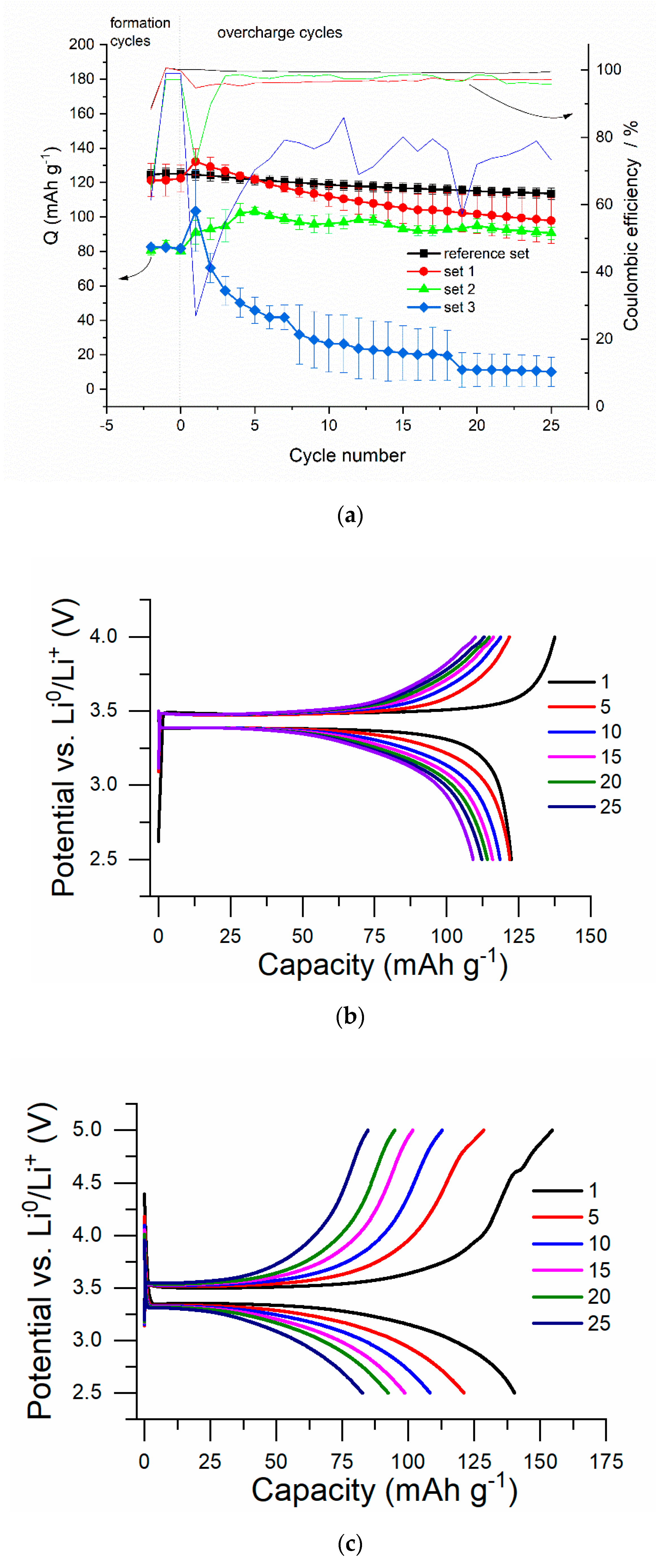
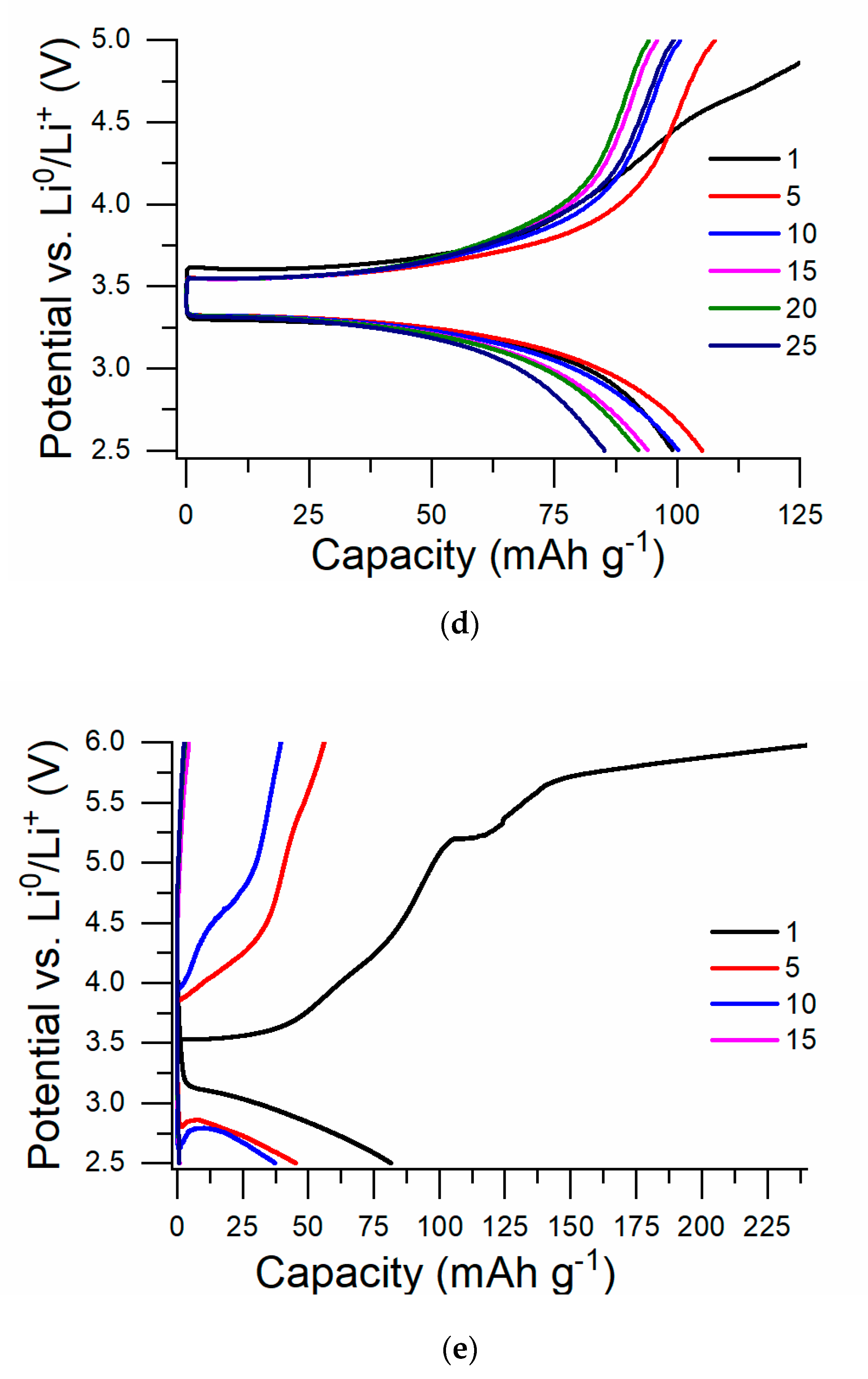
3.1. Results of Overcharging

For testing, the regimes and voltage ranges were selected to simulate a long over-charge (2.5–5.0 V with a current of 0.25 C (set 1)), short-time overcharge (2.5–5.0 V with a current of 1 C (set 2)) and a short overcharge with an excess of the cut-off voltage of the chargers (2.5–6.0 V with a current of 1C (set 3)). Such a choice of overcharge patterns allowed us to investigate the effect of maximum voltage and charge speeds on the stability of the material and to identify the most critical risk factors. For each of the modes, we studied the effect of overcharging on the surface state of the material using XPS, to determine the products of electrolyte decomposition and destruction of electrode components. The changes in the internal crystal structure of LiFePO4 were revealed using XRD.
Charge-discharge test results demonstrated a strong influence of the overcharge mode on the cycling performance of the cells. As seen in Figure 1a,b the cells from the reference set, charged by 0.25 C current to 4.0 V, demonstrated excellent cycling performance and columbic efficiency, close to unity. An increase in the cut-off potential to 5 V, whereby a charge current of 0.25 C is maintained, leads to severe capacity drop from 141 mAh·g−1 to 83 mAh·g−1 after 25 cycles (set 1, Figure 1a,c). As seen from the charge-discharge curves, recorded during several successive cycles of overcharging, the capacity drop is accompanied by small increase in polarization, defined as the difference between the potentials of the plateau of charge and discharge voltages (Figure 1c). It indicates that the increase of the ohmic resistance of the cell is not the main reason of the capacity degradation. The charge voltage profile has the sloped region at overcharge potentials less than 5 V, which is mostly pronounced on the first overcharge cycle. Together with low columbic efficiency of the first overcharge cycle it indicates electrolyte decomposition and cathode interface layer (CEI) formation on the surface of active material. The cells from set 2, overcharged to the same cut-off of 5 V by the higher current (1 C, Figure 1a,d), demonstrated moderate drop of discharge capacity, decreasing from 108 mAh·g−1 in the 1st cycle to 86 mAh·g−1 in the 25th one. The changes on the discharge curve are less pronounced. A comparison of the adverse effects of overcharge on the cycle performance of the cells from set 1 and set 2 allowed us to conclude that the formation of the CEI layer is a slow process, formed to a much lesser extent if the overcharge to 5 V is quick. However, the most drastic capacity loss is observed when overcharging by 1 C current to 6 V (set 3, Figure 1a,e). The overcharge of such potential resulted in both, a polarization increase and change in discharge curve shape. In this case the potential is high enough for oxidation of PO43− ions (5.4 V, [32]), which results in the flattening of the overcharge plateau and consumption of more than 100% of excessive irreversible capacity on the first overcharge cycle. After several overcharge cycles, the shape of the discharge curves of the overcharged cells change from flat, typical for LiFePO4, to inclined. This effect is crucial for sets 1 and 3, and is less pronounced for set 2. An increase in the slope of the discharge voltage profile with an increase in extracted capacity is strong evidence of mass transfer limitations, raised after the overcharge [39]. To confirm the kinetic origin of the observed capacity drop, we have performed C/100 discharge test of one of the cells from set 3 and we were able to discharge the cell to 92% of its theoretical capacity with excellent flat discharge profile. Further confirmation of the absence of mechanical degradation of the cell and the electrode was obtained after the cells were disassembled. The components of all cells were found to be wet by the electrolyte, and the electrodes demonstrated good integrity. It means that the loss in capacity is related to the active material and is not related to the possible dry out of the cell after electrolyte oxidation or electrode exfoliation.

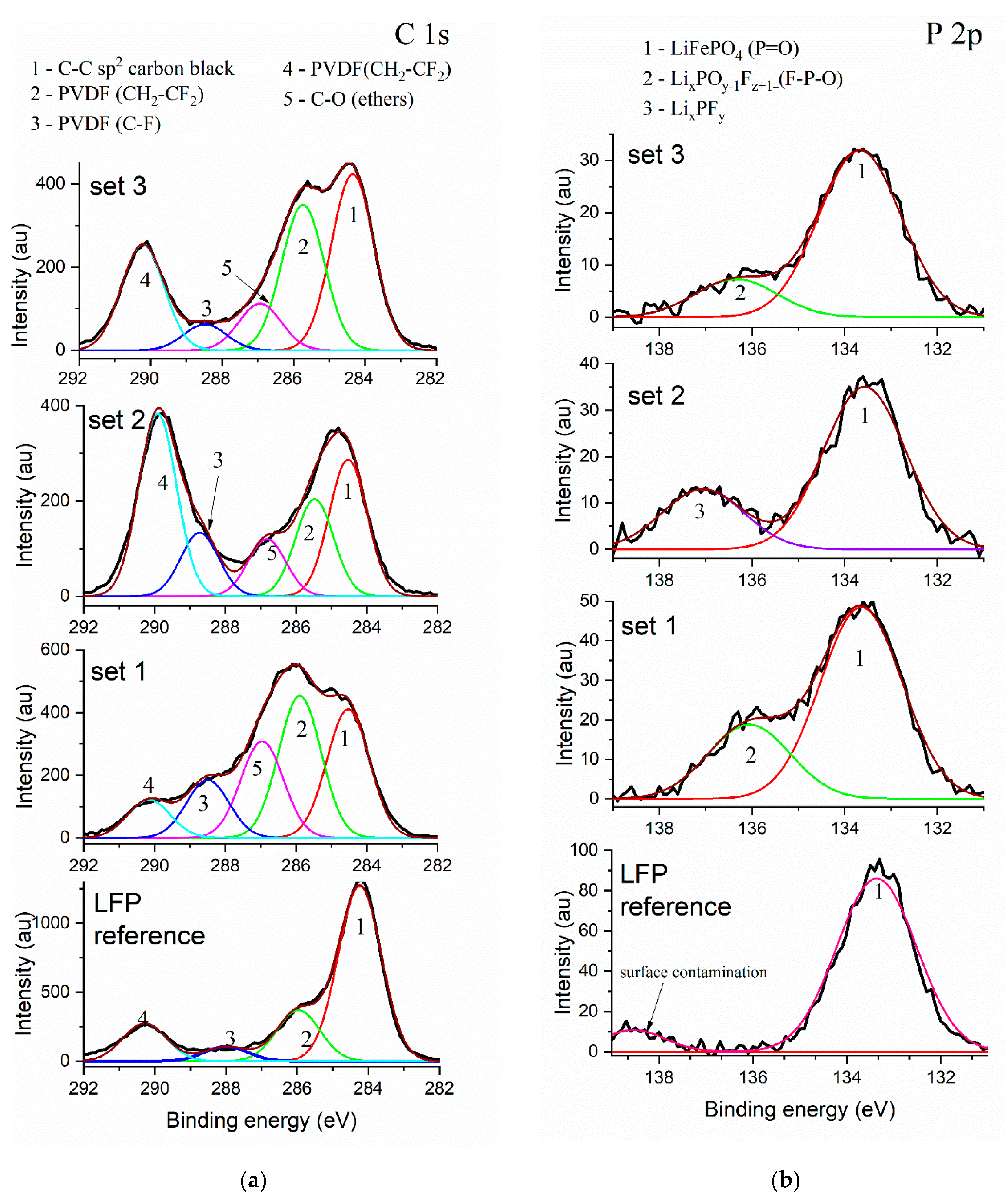
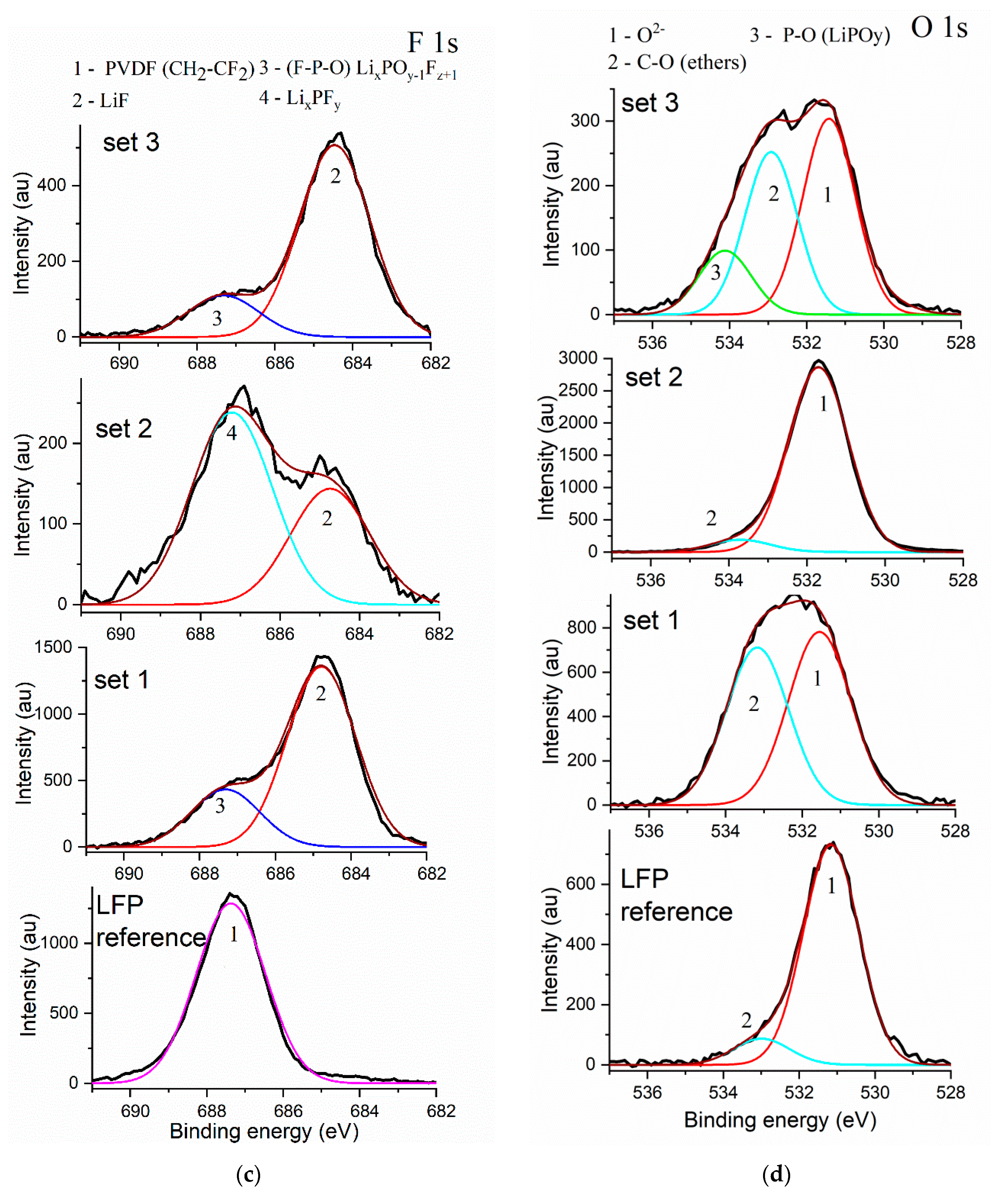
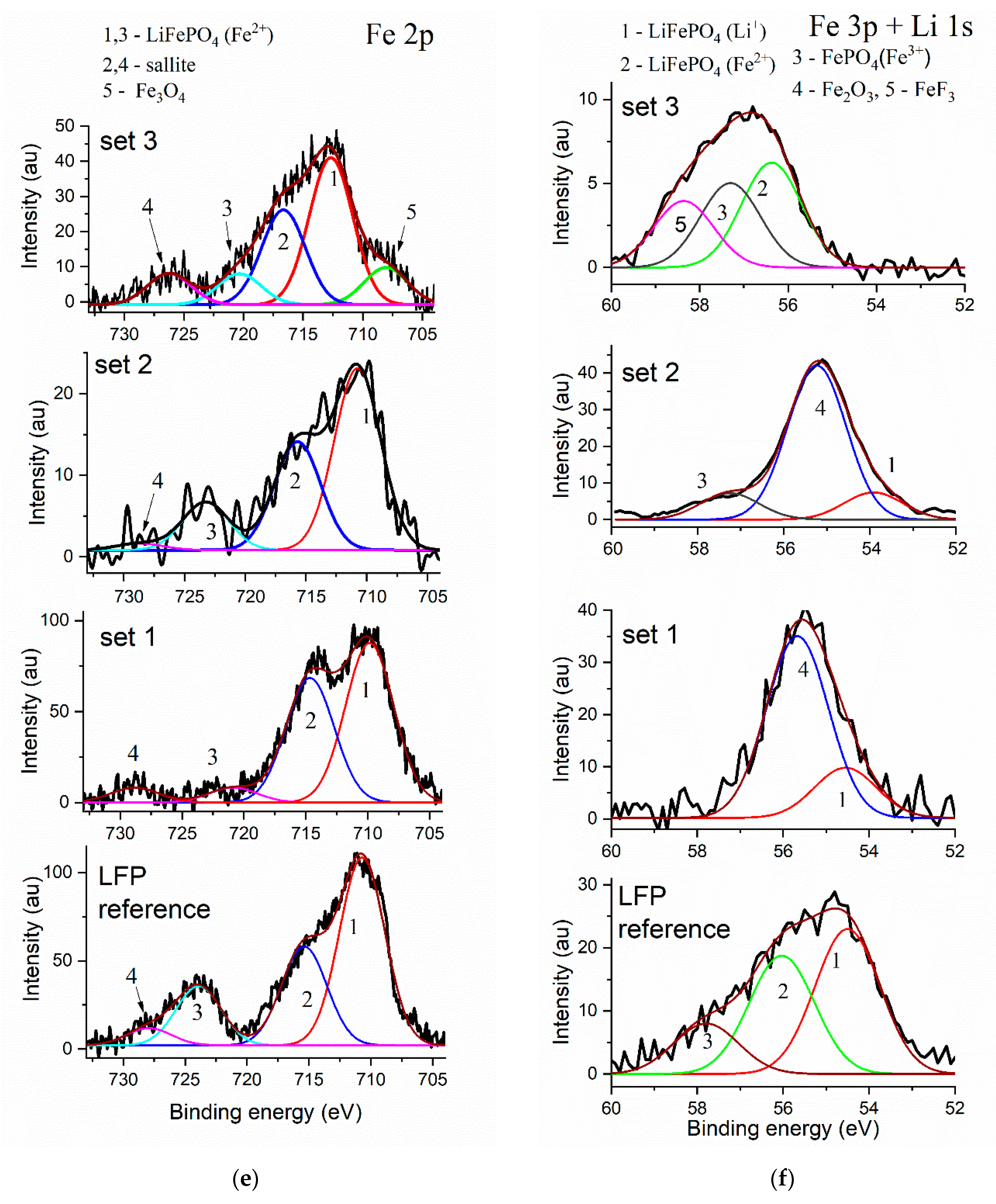
3.2. XPS Measurements

To study changes in the surface of a material during the overcharge, XPS spectra were obtained on a clean reference electrode and sets 1, 2, and 3 after overcharging (Figure 2).
The C 1s spectra of all samples (Figure 2c) contain bands characteristic of the C-C sp2 bond, which indicate the presence of a free surface of carbon black in the sample. In addition, these spectra contain peaks of C-H and C-F bonds in the CH2-CF2 group [10], which correspond to the presence of PVDF. The carbon black and binder peaks persist after overcharging, however, the ratio of their intensities changes (Figure 2a). In contrast to the spectrum of the LFP reference a peak of ethers is detected in all overcharged sets (C-O, about 286.9 eV) [10]. Possibly, appearance of the peak corresponds to the oxidation of the electrolyte under overcharging conditions in case of sets 1, 2, and 3.
In the P 2p spectrum of the LFP reference, the main peak is observed at 133.31 eV, which corresponds to phosphorus P5+ in the PO43− [18,19] (Figure 2b). In overcharged sets, this peak is retained and remains dominant. For sets 1 and 3, a second peak of the F-P-O bond appears at about 136.00 eV (Figure 2b), which can be attributed to fluorine-rich fluorophosphates LixPOy−1Fz+1 [10]. A new peak (137.06 eV) appears on the P 2p spectrum of set 3. It can be assigned to the P-F bond and probably indicates the presence of LixPFy on the surface [10,20].
In the F 1s spectrum of the reference sample (Figure 2c) the only peak at 687.34 eV correspond to the C-F bond in CH2-CF2 binder group [21]. Overcharging of the samples leads to a significant change in the F 1s spectra (Figure 2c). A shoulder appears on the spectra of samples from sets 1 and 3, located for both samples at the same binding energy (686.88–687.05 eV). Based on the results published in [10] this shoulder band can be related to the F-P bond in LixPOy−1.Fz+1. The presence of this component is also confirmed by the P 2p spectrum of these samples (Figure 2b).
A peak of 531.20 eV on the O 1s spectra of all studied sets is ascribed to the lattice oxygen and additional peak position at 533.1 eV is assigned to C-O, corresponding to the functional group absorbed on the electrodes [40,41] (Figure 2d). The O1s spectra of set 3 contains peak at 534.1 corresponding to P-O bond in LiPOy [10], which is produced by the electrode over-oxidation.
The Fe 2p spectra of all sets show two peaks at 710.6 eV and 720.8 eV, corresponding to Fe2p3/2 and Fe2p1/2 [42,43]. Two satellite peaks at higher binding energy (715.3 eV and 728.6 eV) are typical of the transition metal ions with partially filled d-orbitals. Fe ion energy levels multiply split [18,44]. The Fe 2p spectra of set 3 contain additional peak at 708.04 eV corresponding to Fe-O bond in Fe3O4 [45]. The peak appears from the destruction of the cathode material in the severe overcharging conditions, applied to set 3. The small deviation of the main peak position, in this case, also indicates the changes in the cathode material after overcharging.
Analysis of the spectrum of the reference electrode in the range of Fe 3p and Li 1s bands (Figure 2f) reveals the three peaks, corresponding to Fe 3p (Fe2+) at 55.74 eV and Li 1s (Li+) at 54.70 eV in composition of LiFePO4 [19] and 3p (Fe2+) in FePO4 at 57.8 eV [46]. In the similar spectrum of set 1, Fe 3p bands are absent, but a new peak at 55.7 eV is observed, which refers to Fe3+ in Fe2O3 [47]. On Li 1s spectrum of set 2, in addition to these two peaks, peak at 57.8 eV is observed, which can be attributed to 3p (Fe2+) in FePO4 [46]. Set 3 has different spectrum. The peak of Li+ disappears. Peaks corresponding to Fe2+ and Fe3+ are still distinguishable, and a new peak at 58.4 eV, corresponding to Fe3+ in FeF3, appears.
Based on the analysis of XPS data in Table 1, we list the compounds that were found on the surface of LFP samples after overcharging the cells in different modes. As seen from the table, only the main components of the electrode are present on the surface of the LFP reference: LiFePO4, carbon black and PVDF (with the exception of a small amount of contaminants). A comparison of sets 1 and 2 shows that the surface of set 2 is less affected by overcharge, and its surface layer composition remains close to the reference one. In the case of set 1, the carbon black fraction decreases due to the appearance of new products and an increase in their signals on the surface, and the proportion of LiFePO4 becomes comparable with contaminations, which indicates the formation of layers of electrolyte decomposition products, both on the surface of the active material and on the surface of carbon particles. The qualitative difference between the two samples overcharged by different currents is the formation of Fe2O3 as over-oxidation product. In the case of set 2, the dominant components of the surface layer are LixPFy and Fe2O3. On the surface of set 1 overcharged by 0.25 C rate, the main component of SEI is LiF, and ethers.
The appearance of bands corresponding to LixPFy is observed in the F spectrum for this sample. Here we can conclude that the overcharge in the 1 C mode (set 2) is less critical for the half cell, either, due to the sluggish kinetics of product formation, or due to the greater polarization and the influence of internal resistance on the overall voltage. This conclusion is confirmed by the more stable charge-discharge characteristics of set 2 (Figure 1b).
A comparison between the Fe 2p spectra of sets 2 and 3 demonstrates appearance of a new peak corresponding to Fe3O4, which is a product of the cathode over-oxidation. Additionally, only for set 3, another product of high-voltage overcharge, FeF3, is indicated and the peak corresponding to Li+ in LiFePO4 disappears.
From a comparison of XPS and charge-discharge curves it is clear that the increase in the charge voltage and the decrease in the charge current lead to the appearance of surface layers that increase the polarization of the electrode (Table 1). At the same time, a quick overcharge (as in the case of set 2) proceeds practically without consequences for the cathode. We can arrange the overcharge patterns in a row from higher to lover destructive effect as follows:
1 C, 2.5–6 V > 0.25 C, 2.5–5 V > 1 C, 2.5–5 V

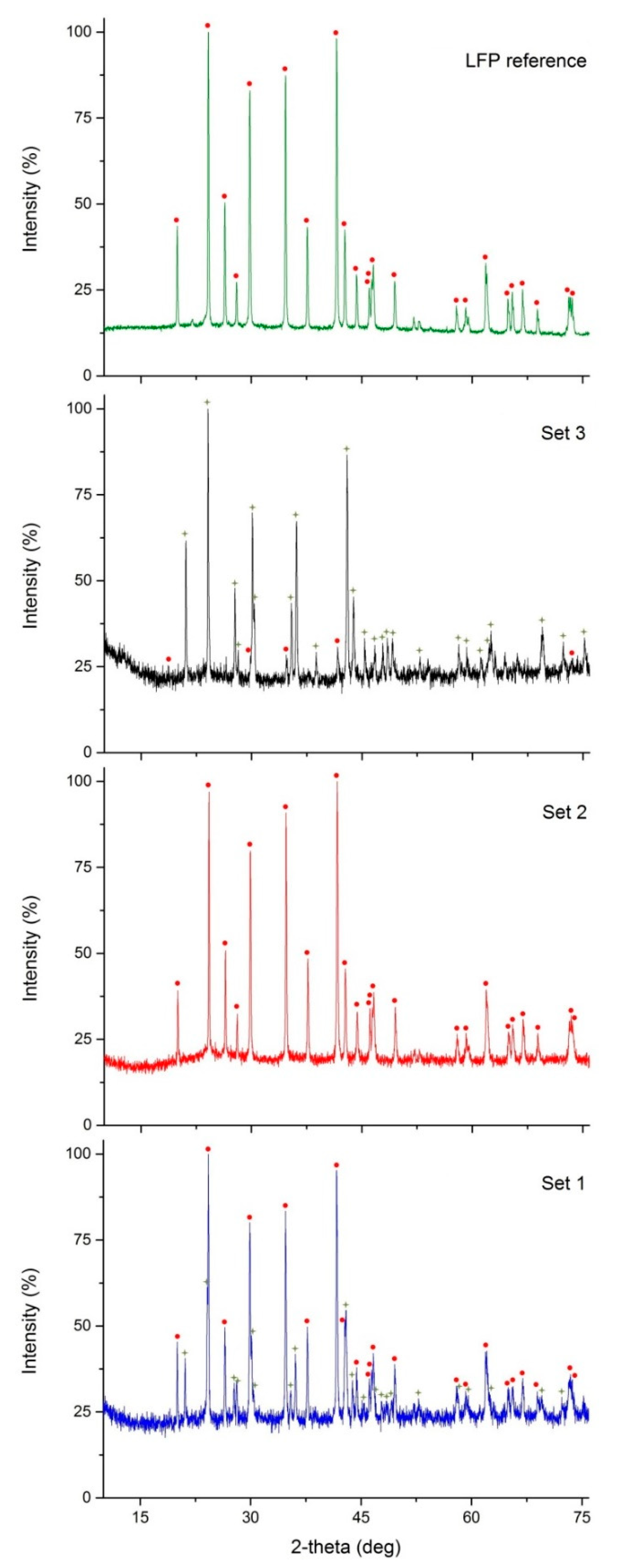
3.3. XRD Measurements

The samples LFP reference, set 1, set 2, set 3 were investigated using powder X-ray diffraction. The phase identification of the XRD-pattern was performed using the software PDXL2 (PDXL2 Software Version 2.7.2.0 Copyright 2007–2016 Rigaku Corporation, Tokyo, Japan), coupled with the database Powder Diffraction File (PDF-2 ICDD Release 2016 RDB). Quantitative phase analysis was performed with Rietveld method using TOPAS program (TOPAS Version 5 Copyright 1999–2014 Bruker AXS, Karlsruhe, Germany. www.bruker.com) coupled with the database ICSD 2019/1 (Inorganic Crystal Structure Database) for each phase (Table 2).
The XRD-patterns with phase determination of LFP reference, set 1, set 2, set 3 are reported in Figure 3.
The analysis of the XRD powder patterns of the electrodes after overcharging (Figure 3) showed that set 2 undergoes the smallest destruction of electrode components. It correlates with XPS data, which means that LFP-based cathodes can withstand fast and short-term overcharge to 5 V. Set 3 has the most significant changes, which indicates the destruction of the active material. Despite that, the cell was disassembled in the discharged state, the electrode contains mostly delithiated FePO4 phase, which indicates that overcharging makes reversible the lithiation of LFP cathode impossible. A similar destruction of the material is observed when overcharging by small current to 5 V (set 1, Figure 3).
These results correlate with the obtained electrochemical data, demonstrating that LFP set 3, together with forming the surface layers and changing the diffraction pattern, which showed the lowest discharge capacity at the 25th cycle (Figure 1c).
Quantitative phase analyses of LFP reference and sets 13 (Table 2) also comfirmed the total irreversibility of set 3 delithiation and the significant change of set 1 phase composition.
The combined results of XPS, XRD, and electrochemical tests can be used to describe the behavior of LFP electrodes at different overcharging modes. The fast overcharging of the cell in 25 cycles in a 1 C current to 5.0 V (set 2) leads to minor changes in the cathode surface layer compared to reference LFP sample. The appearance of small amounts of LiF and fluorophosphates is observed, while the main XPS signals belong to LiFePO4. The carbon black signal prevails over the PVDF and carboxylate signals. Accordingly, such overcharge patterns will not lead to battery failure, even if several overcharges occur over the life of the battery. However, in the case of repeated overcharging at low current (0.25 C) to the same potential (5.0 V, set 1), the electrolyte decomposition products form an insulating layer, containing ether groups, on the electrode surface. The situation is worse for set 3, overcharged with a current of 1 C to 6.0 V. This overcharge potential is high enough for destruction of the material itself. The same electrolyte decomposition process, together with partial destruction of LFP lattice and Fe migration to surface layer in form of FeF3 and Fe3O4, leads to deterioration in electrical conductivity and diffusion rate of lithium ions. A small amount of active material and constant temperature of the coin cells avoids thermal runaway and adverse processes, caused by cell heating. However, most decomposition products, attributed to high-temperature reactions (e.g., LiF and iron polyphosphates [34]) are found on the surface of the sample, charged to 6 V and, to a less extent, on the sample, charged to 5 V by low rate. It indicates that the potential of the cathode is the critical parameter for the failure of the overcharged cell, even if the good thermal management of the cell prevents it thermal runaway.

4. Conclusions

The study of the electrochemical properties, crystal structures, and surfaces of electrodes, based on lithium iron phosphate, revealed the effect of the battery overcharge mode on the degree of the destructive changes in the electrode. Experiments that were performed in coin half-cells enabled focus on the electrode potential effects and exclude thermal runaway, typical for overcharge tests of commercial cells, as well as the influence of anode material on cell voltage. It was demonstrated that a short-time overcharge of up to 5.0 V by high currents is the least destructive and does not lead to an irreversible changes in the cathode material. However, an increase in the upper limit of the potential to 6.0 V or a decrease in the charge current to 0.25 C leads to, both, the formation of surface layers of electrolyte decomposition products, an increase in the polarization of the battery, and to irreversible slowdown of the lithiation kinetics of the active material. Thus, despite the well-known tolerance of LiFePO4-based batteries to overcharge, a long overcharge time or high cut-off voltage leads to destructive changes in the cathode, and should be avoided.

Author Contributions

Conceptualization, O.V.L., E.V.A., E.V.B.; methodology, E.V.B., D.V.S.; validation, O.V.L.; investigation, E.V.B., D.V.S.; resources, O.V.L.; data curation, E.V.B.; writing—original draft preparation, E.V.B.; writing—review and editing, O.V.L., E.V.A., A.N.Y.; visualization, E.V.A., E.V.B.; supervision, O.V.L.

Funding

This research was funded by the Russian Science Foundation, grant number 19-19-00175.

Acknowledgments

Scientific research was partially performed at the Research park of Saint Petersburg State University: Centre for X-ray Diffraction Studies, Chemistry Educational Centre, Centre for Physical Methods of Surface Investigation, Centre for Optical and Laser Materials Research.

Conflicts of Interest

The authors declare no conflict of interest.

References

  1. Simon, P.; Gogotsi, Y.; Dunn, B. Where Do Batteries End and Supercapacitors Begin? Science 2014, 343, 1210–1211. [Google Scholar] [CrossRef] [Green Version]
  2. Béguin, F.; Presser, V.; Balducci, A.; Frackowiak, E. Carbons and Electrolytes for Advanced Supercapacitors. Adv. Mater. 2014, 26, 2219–2251. [Google Scholar] [CrossRef]
  3. Frackowiak, E. Carbon materials for supercapacitor application. Phys. Chem. Chem. Phys. 2007, 9, 1774–1785. [Google Scholar] [CrossRef]
  4. Sun, Y.; Zheng, G.; Seh, Z.W.; Liu, N.; Wang, S.; Sun, J.; Lee, H.R.; Cui, Y. Graphite-Encapsulated Li-Metal Hybrid Anodes for High-Capacity Li Batteries. Chem 2016, 1, 287–297. [Google Scholar] [CrossRef]
  5. Sun, Y.; Lee, H.-W.; Seh, Z.W.; Zheng, G.; Sun, J.; Li, Y.; Cui, Y. Lithium Sulfide/Metal Nanocomposite as a High-Capacity Cathode Prelithiation Material. Adv. Energy Mater. 2016, 6. [Google Scholar] [CrossRef]
  6. Sun, Y.; Lee, H.-W.; Zheng, G.; Seh, Z.W.; Sun, J.; Li, Y.; Cui, Y. In Situ Chemical Synthesis of Lithium Fluoride/Metal Nanocomposite for High Capacity Prelithiation of Cathodes. Nano Lett. 2016, 16, 1497–1501. [Google Scholar] [CrossRef] [PubMed]
  7. Sun, Y.; Lee, H.-W.; Seh, Z.W.; Liu, N.; Sun, J.; Li, Y.; Cui, Y. High-capacity battery cathode prelithiation to offset initial lithium loss. Nat. Energy 2016, 1, 15008. [Google Scholar] [CrossRef]
  8. Jeżowski, P.; Fic, K.; Crosnier, O.; Brousse, T.; Béguin, F. Lithium rhenium(vii) oxide as a novel material for graphite pre-lithiation in high performance lithium-ion capacitors. J. Mater. Chem. A 2016, 4, 12609–12615. [Google Scholar] [CrossRef]
  9. Jezowski, P.; Crosnier, O.; deunf, E.; Poizot, P.; Beguin, F.; Brousse, T. Safe and recyclable lithium-ion capacitors using sacrificial organic lithium salt. Nat. Mater. 2018, 17. [Google Scholar] [CrossRef] [PubMed]
  10. Schulz, N.; Hausbrand, R.; Wittich, C.; Dimesso, L.; Jaegermann, W. XPS-Surface Analysis of SEI Layers on Li-Ion Cathodes: Part II. SEI-Composition and Formation inside Composite Electrodes. J. Electrochem. Soc. 2018, 165, A833–A846. [Google Scholar] [CrossRef]
  11. Peled, E.; Menkin, S. Review - SEI: Past, present and future. J. Electrochem. Soc. 2017, 164, A1703–A1719. [Google Scholar] [CrossRef]
  12. Xu, F.; He, H.; Liu, Y.; Dun, C.; Ren, Y.; Liu, Q.; Wang, M.; Xie, J. Failure Investigation of LiFePO 4 Cells under Overcharge Conditions. J. Electrochem. Soc. 2012, 159, A678–A687. [Google Scholar] [CrossRef]
  13. Ouyang, D.; Liu, J.; Chen, M.; Wang, J. Investigation into the fire hazards of lithium-ion batteries under overcharging. Appl. Sci. 2017, 7, 1314. [Google Scholar] [CrossRef] [Green Version]
  14. Du Pasquier, A.; Plitz, I.; Menocal, S.; Amatucci, G. A comparative study of Li-ion battery, supercapacitor and nonaqueous asymmetric hybrid devices for automotive applications. J. Power Sources 2003, 115, 171–178. [Google Scholar] [CrossRef]
  15. Kikkawa, J.; Terada, S.; Gunji, A.; Nagai, T.; Kurashima, K.; Kimoto, K. Chemical states of overcharged LiCoO2 particle surfaces and interiors observed using electron energy-loss spectroscopy. J. Phys. Chem. C 2015, 119, 15823–15830. [Google Scholar] [CrossRef]
  16. Yang, Z.; Yang, W.; Evans, D.G.; Li, G.; Zhao, Y. Enhanced overcharge behavior and thermal stability of commercial LiCoO2 by coating with a novel material. Electrochem. commun. 2008, 10, 1136–1139. [Google Scholar] [CrossRef]
  17. Dahn, J.; Fuller, E.; Obrovac, M.; Vonsacken, U. Thermal stability of LixCoO2, LixNiO2 and λ-MnO2 and consequences for the safety of Li-ion cells. Solid State Ionics 1994, 69, 265–270. [Google Scholar] [CrossRef]
  18. Castro, L.; Dedryvère, R.; El Khalifi, M.; Lippens, P.-E.; Bréger, J.; Tessier, C.; Gonbeau, D. The Spin-Polarized Electronic Structure of LiFePO4 and FePO4 Evidenced by in-Lab XPS. J. Phys. Chem. C 2010, 114, 17995–18000. [Google Scholar] [CrossRef]
  19. Xiong, W.; Hu, Q.; Liu, S. A novel and accurate analytical method based on X-ray photoelectron spectroscopy for the quantitative detection of the lithium content in LiFePO4. Anal. Methods 2014, 6, 5708–5711. [Google Scholar] [CrossRef]
  20. Chagnes, A.; Światowska, J. Electrolyte and Solid-Electrolyte Interphase Layer in Lithium-Ion Batteries; IntechOpen: London, UK, 2012; ISBN 978-953-51-0077-5. [Google Scholar]
  21. Dedryvère, R.; Maccario, M.; Croguennec, L.; Le Cras, F.; Claude, D.; Gonbeau, D. X-Ray Photoelectron Spectroscopy Investigations of Carbon-Coated LixFePO4 Materials. Chem. Mater. 2008, 20, 7164–7170. [Google Scholar] [CrossRef]
  22. Bloom, I.; Dietz Rago, N.; Sheng, Y.; Li, J.; Wood, D.L.; Steele, L.A.; Lamb, J.; Spangler, S.; Grosso, C.; Fenton, K. Effect of overcharge on lithium-ion cells: Silicon/graphite anodes. J. Power Sources 2019, 432, 73–81. [Google Scholar] [CrossRef]
  23. Bareño, J.; Dietz Rago, N.; Dogan, F.; Graczyk, D.G.; Tsai, Y.; Naik, S.R.; Han, S.-D.; Lee, E.; Du, Z.; Sheng, Y.; et al. Effect of overcharge on Li(Ni0.5Mn0.3Co0.2)O2/graphite lithium ion cells with poly(vinylidene fluoride) binder. III — Chemical changes in the cathode. J. Power Sources 2018, 385, 165–171. [Google Scholar] [CrossRef]
  24. Bloom, I.; Bareño, J.; Dietz Rago, N.; Dogan, F.; Graczyk, D.G.; Tsai, Y.; Naik, S.R.; Han, S.-D.; Lee, E.; Du, Z.; et al. Effect of overcharge on Li(Ni0.5Mn0.3Co0.2)O2 cathodes: NMP-soluble binder. II — Chemical changes in the anode. J. Power Sources 2018, 385, 156–164. [Google Scholar] [CrossRef]
  25. Dietz Rago, N.; Bareño, J.; Li, J.; Du, Z.; Wood, D.L.; Steele, L.A.; Lamb, J.; Spangler, S.; Grosso, C.; Fenton, K.; et al. Effect of overcharge on Li(Ni0.5Mn0.3Co0.2)O2/Graphite lithium ion cells with poly(vinylidene fluoride) binder. I - Microstructural changes in the anode. J. Power Sources 2018, 385, 148–155. [Google Scholar] [CrossRef]
  26. Grosvenor, A.P.; Kobe, B.A.; Biesinger, M.; Mcintyre, N. Investigation of Multiplet Splitting of Fe 2p XPS Spectra and Bonding in Iron Compounds. Surf. Interface Anal. 2004, 36, 1564–1574. [Google Scholar] [CrossRef]
  27. Wang, Y. Iron(III) phosphate (FePO4) by XPS. Surf. Sci. Spectra 2002, 9. [Google Scholar] [CrossRef]
  28. Anishchenko, D.V.; Levin, O.V.; Malev, V.V. Quasi-equilibrium voltammetric curves of polaron-conducting polymer films. Electrochim. Acta 2016, 188, 480–489. [Google Scholar] [CrossRef]
  29. Ellis, B.L.; Makahnouk, W.R.M.; Makimura, Y.; Toghill, K.; Nazar, L.F. A multifunctional 3.5 V iron-based phosphate cathode for rechargeable batteries. Nat. Mater. 2007, 6, 749–753. [Google Scholar] [CrossRef]
  30. Chen, G.; Richardson, T.J. Thermal instability of Olivine-type LiMnPO4 cathodes. J. Power Sources 2010, 195, 1221–1224. [Google Scholar] [CrossRef]
  31. Yuan, L.-X.; Wang, Z.-H.; Zhang, W.-X.; Hu, X.-L.; Chen, J.-T.; Huang, Y.-H.; Goodenough, J.B. Development and challenges of LiFePO4 cathode material for lithium-ion batteries. Energy Environ. Sci. 2011, 4, 269–284. [Google Scholar] [CrossRef]
  32. Julien, M.C.; Mauger, A.; Zaghib, K.; Groult, H. Comparative Issues of Cathode Materials for Li-Ion Batteries. Inorganics 2014, 2. [Google Scholar] [CrossRef] [Green Version]
  33. Hu, G.; Xie, X.; Peng, Z.; Du, K.; Gan, Z.; Xu, L.; Wang, Y.; Cao, Y. Novel synthesis of FePO4·2H2O nanoparticles as a precursor of LiFePO4/C cathode material for lithium ion batteries by microreaction technology. Solid State Ionics 2019, 340, 115014. [Google Scholar] [CrossRef]
  34. Golubkov, A.W.; Scheikl, S.; Planteu, R.; Voitic, G.; Wiltsche, H.; Stangl, C.; Fauler, G.; Thaler, A.; Hacker, V. Thermal runaway of commercial 18650 Li-ion batteries with LFP and NCA cathodes—Impact of state of charge and overcharge. RSC Adv. 2015, 5, 57171–57186. [Google Scholar] [CrossRef] [Green Version]
  35. Larsson, F.; Mellander, B.-E. Abuse by External Heating, Overcharge and Short Circuiting of Commercial Lithium-Ion Battery Cells. J. Electrochem. Soc. 2014, 161, A1611–A1617. [Google Scholar] [CrossRef]
  36. Liu, Y.; Xie, J. Failure Study of Commercial LiFePO4 Cells in Overcharge Conditions Using Electrochemical Impedance Spectroscopy. J. Electrochem. Soc. 2015, 162, A2208–A2217. [Google Scholar] [CrossRef]
  37. Cui, W.; He, Y.-B.; Tang, Z.-Y.; Yang, Q.-H.; Xu, Q.; Su, F.-Y.; Ma, L. Improvement of overcharge performance using Li4Ti5O12 as negative electrode for LiFePO4 power battery. J. Solid State Electrochem. 2012, 16, 265–271. [Google Scholar] [CrossRef]
  38. Li, J.; Dong, S.; Wang, C.; Hu, Z.; Zhang, Z.; Zhang, H.; Cui, G. A study on the interfacial stability of the cathode/polycarbonate interface: implication of overcharge and transition metal redox. J. Mater. Chem. A 2018, 6, 11846–11852. [Google Scholar] [CrossRef]
  39. Nazri, G.-A.; Pistoia, G. Lithium Batteries: Science and Technology; Springer: Berlin, Germany, 2009. [Google Scholar]
  40. Rybachuk, M.; Bell, J.M. The effect of sp2 fraction and bonding disorder on micro-mechanical and electronic properties of a-C:H films. Thin Solid Films 2007, 515, 7855–7860. [Google Scholar] [CrossRef] [Green Version]
  41. Fedorková, A.; Oriňáková, R.; Oriňák, A.; Kupková, M.; Wiemhöfer, H.-D.; Audinot, J.N.; Guillot, J. Electrochemical and XPS study of LiFePO4 cathode nanocomposite with PPy/PEG conductive network. Solid State Sci. 2012, 14, 1238–1243. [Google Scholar] [CrossRef]
  42. Saravanan, K.; Reddy, M. V; Balaya, P.; Gong, H.; Chowdari, B.V.R.; Vittal, J.J. Storage performance of LiFePO4 nanoplates. J. Mater. Chem. 2009, 19, 605–610. [Google Scholar] [CrossRef]
  43. Muruganantham, R.; Sivakumar, M.; Subadevi, R. Synthesis and electrochemical characterization of olivine-type lithium iron phosphate cathode materials via different techniques. Ionics 2016, 22, 1557–1565. [Google Scholar] [CrossRef]
  44. Bhuvaneswari, M.S.; Bramnik, N.N.; Ensling, D.; Ehrenberg, H.; Jaegermann, W. Synthesis and characterization of Carbon Nano Fiber/LiFePO4 composites for Li-ion batteries. J. Power Sources 2008, 180, 553–560. [Google Scholar] [CrossRef]
  45. McIntyre, N.S.; Zetaruk, D.G. X-ray photoelectron spectroscopic studies of iron oxides. Anal. Chem. 1977, 49, 1521–1529. [Google Scholar] [CrossRef]
  46. Barbaux, Y.; Dekiouk, M.; Le Maguer, D.; Gengembre, L.; Huchette, D.; Grimblot, J. Bulk and surface analysis of a Fe-P-O oxydehydrogenation catalyst. Appl. Catal. A Gen. 1992, 90, 51–60. [Google Scholar] [CrossRef]
  47. Allen, G.C.; Harris, S.J.; Jutson, J.A.; Dyke, J.M. A study of a number of mixed transition metal oxide spinels using X-ray photoelectron spectroscopy. Appl. Surf. Sci. 1989, 37, 111–134. [Google Scholar] [CrossRef]
Figure 1. (a) Cycle performance (each point is averaged by three samples) and (be) charge and discharge curves of the representative sample of the Li/LiFePO4 cells with 1 M LiPF6 in EC/DEC (1:1 v/v) electrolyte, normally charged by 1 C current in the voltage range 2.5–4.0 V (reference set) and overcharged by: current 0.25 C in the voltage range 2.5–5.0 V (set 1); current 1 C in the voltage range 2.5–5.0 V (set 2); current 1 C in the voltage range 2.5–6.0 V (set 3).
Energies 12 04652 g001aEnergies 12 04652 g001b
Figure 2. XPS-spectra of (a) C 1s, (b) P 2p, (c) F 1s, (d) O 1s, (e) Fe 2p, (f) Li 1s + Fe 3p of the surface of LiFePO4 (LFP) electrodes after overcharging by 0.25 C current to 5.0 V (set 1); by 1C current to 5.0 V (set 2); by 1C current to 6.0 V (set 3), and LFP reference, which has the same composition, but not treated electrochemically.
Energies 12 04652 g002aEnergies 12 04652 g002bEnergies 12 04652 g002c
Figure 3. The XRD powder patterns of LFP reference, set 1, set 2, set 3 with phase determination. Red circles—reflections of LiFePO4 (PDF-2 ICDD 01-072-7845). Green stars—reflections of FePO4 (PDF-2 ICDD 01-070-6685).
Energies 12 04652 g003
Table 1. The products identified by X-ray photoelectron spectroscopy (XPS) on the surface of the reference and the overcharged samples.
ElementLFP ReferenceSet 1 (LFP Overcharged by 0.25 C Current to 5.0 V)Set 2 (LFP Overcharged by 1 C Current to 5.0 V)Set 3 (LFP Overcharged by 1 C Current to 6.0 V)
CCarbon black > PVDFPVDF > Carbon black > ethersCarbon black > PVDF > ethersCarbon black > PVDF > ethers
PLiFePO4 >> surface contaminationLiFePO4 > LixPOy−1Fz+1LiFePO4 > LixPFyLiFePO4 > LixPOy−1Fz+1
FPVDFLiF > LixPOy−1Fz+1LixPFy > LiFLiF > LixPOy−1Fz+1
OLiFePO4 >> ethersLiFePO4 > ethersLiFePO4 >> ethersLiFePO4 > ethers > LiPOy
Li + FeLiFePO4 > FePO4Fe2O3 > LiFePO4Fe2O3 > LiFePO4 > FePO4LiFePO4 ≥ FePO4 ≥ FeF3
FeLiFePO4LiFePO4LiFePO4LiFePO4>Fe3O4
Table 2. Quantitative phase analyses of LFP reference, set 1, set 2, set 3 (wt. %) using Rietveld method.
PhaseLFP ReferenceSet 1Set 2Set 3
LiFePO4100.074.6 (6)100.09.2 (12)
FePO4-25.4 (6)-90.8 (12)
Rp (%) 3.384.574.134.85
Notes: * R P = Σ | y i o b s y i c a l c | y i o b s —reliability factor between the experimental and calculated XRD pattern, yi– intensity at each experimental point of XRD pattern.

