Article

Analysis of a PM Linear Generator with Double Translators for Complementary Energy Generation Platform

1
Department of Electrical Engineering, Jinling Institute of Technology, Nanjing 211169, China
2
School of Electrical Engineering, Southeast University, Nanjing 210096, China
*
Author to whom correspondence should be addressed.
Energies 2019, 12(24), 4606; https://doi.org/10.3390/en12244606
Submission received: 7 November 2019 / Revised: 28 November 2019 / Accepted: 30 November 2019 / Published: 4 December 2019

Abstract

:
This paper presents a tubular permanent magnet (PM) linear generator (TPMLG) with one single stator and double translators for complementary energy generation platform. Moreover, groups of Halbach PM magnetized structure for double translators is applied to increase the radial air gap flux density and to decrease the axial air gap flux density in the TPMLG. Based on the linear generator model and finite element method (FEM), the radial air gap flux density and axial air gap flux density in the two translator of the TPMLG is calculated and analyzed comparatively. Magnet field distribution of the TPMLG with groups of Halbach PM magnetized structure is illustrated, no-load performance at constant velocity and at sine velocity is analyzed, respectively, and comparing with the radial magnetization PM, the detent force is analyzed contrastively. Finally, this study proposed an experiment system consisting of a TPMLG with a single translator, a cylindrical float and wave flume to verify the analysis results. Through comparative analyses, the proposed TPMLG with double translators and groups of Halbach PM magnetized structure fulfill the requirements of complementary energy generation platform systems.

1. Introduction

In the last few decades, fossil fuels have been the main energy source, and most of electric power in the world has been generated from it [1]. With the increase demand of clean and renewable energy sources, many new types of energy power generation appear in the last 10 years [2]. Wave energy converter systems (WECs) have been studied by scholars in the world, such as in the UK, Portugal, the Netherlands, Denmark, etc. According to the installation position of the WECs, the system can be divided into on-shore type and offshore type (at sea), such as Pelamis and wave dragon are offshore type, and Oscillating Water Column (OWC) is on-shore type [3,4]. The former is placed in deep sea, where the density of wave energy is high; however, it is easily damaged in the storm. The latter has a large capacity and high conversion efficiency, but the volume is large and the investment cost is high.
Based on the theory of energy conversion, the WEC system is divided into two types that three stages energy conversion WECs and direct-drive WECs (D-DWECs) [5,6]. The operation process of the former type is that the wave energy obtained by the first stage conversion is firstly converted into mechanical energy by the second stage conversion, such as turbines and the hydraulic gear. Then, the mechanical energy is converted into electrical power in the last stage conversion by rotary generator [7]. In D-DWECs, the middle structure of WECs is abandoned and the conversion efficiency of D-DWECs is improved, with, for example, the Archimedes Wave Swing (AWS) and Point-absorber WECs. However, the conversion efficiency of such single energy power generation systems is low, and energy cost is high.
As energy generation technology develops, lots of types of linear generators for D-DWECs have aroused wide attention and discussion, such as switched reluctance linear generator, magnetic flux switching linear generator, PM synchronous linear generator, etc. In reference [8], a PM linear model with electrical damping circuits was proposed and applied in point-absorber WECs, which suit the region with low wave density. The authors of reference [9] proposed a new magnetic flux switching linear generator for AWS, and the generator is more efficient than other rotational generators. In reference [10], the authors proposed a tubular PM linear generator for D-DWECs, the average power of 2 kW can be obtained in the experiment. In reference [11], a PM linear generator applied in D-DWECs was studied by the British scientist Mueller. A hollow winding and iron coreless structure were adopted to decrease the detent force, and the modular structure is adopted to increase the conversion efficiency of generator. In reference [12], the authors proposed a buoy D-DWECs with a TPMLG, and the characteristics were studied in the condition of no-load and load. However, for when wave power density is low, there have been some challenges for the generators adopted in D-DWECs, such as larger volume of the device, lower energy conversion efficiency and special motor structure to match the energy conversion system.
This work proposes an energy complementary generation floating platform consisting of wind energy and wave energy. A TPMLG with double translators is installed on the D-DWECs of the energy complementary platform. This platform can provide better power quality and higher energy density than single D-DWECs or single wind system. Firstly, the configuration of the complementary platforms and operation principle of the generator are introduced. Magnetic field analysis model for TPMLG with the groups of Halbach PM magnetized structure is proposed, and then, the double translators with PM arrays are analyzed and optimized. Secondly, the principle of the radial magnetic flux density increase is studied to improve magnetic energy density and output voltage amplitude, to decrease the total harmonic distortion (THD) of electromotive force (EMF) waveform of the generator. The axial magnetic flux density and the axial detent force are reduced by using different PM structures. Then, the performance parameters consisting of magnet field distribution, the radial air gap flux density and axial air gap flux density, EMF, and the detent force are calculated and analyzed contrastively. Finally, the analysis results and test results show that compared with traditional linear generator, double translators structure with groups of Halbach PM magnetized structure can meet demands such as enough air-gap flux density, low detent force ripple, high peak of EMF and flexible structure. For the contrastive analysis results agree with the finite element method (FEM) results, the TPMLG model with double translators structure is accurate. Furthermore, the proposed model meets the requirements of wind and wave complementary energy generation platform.

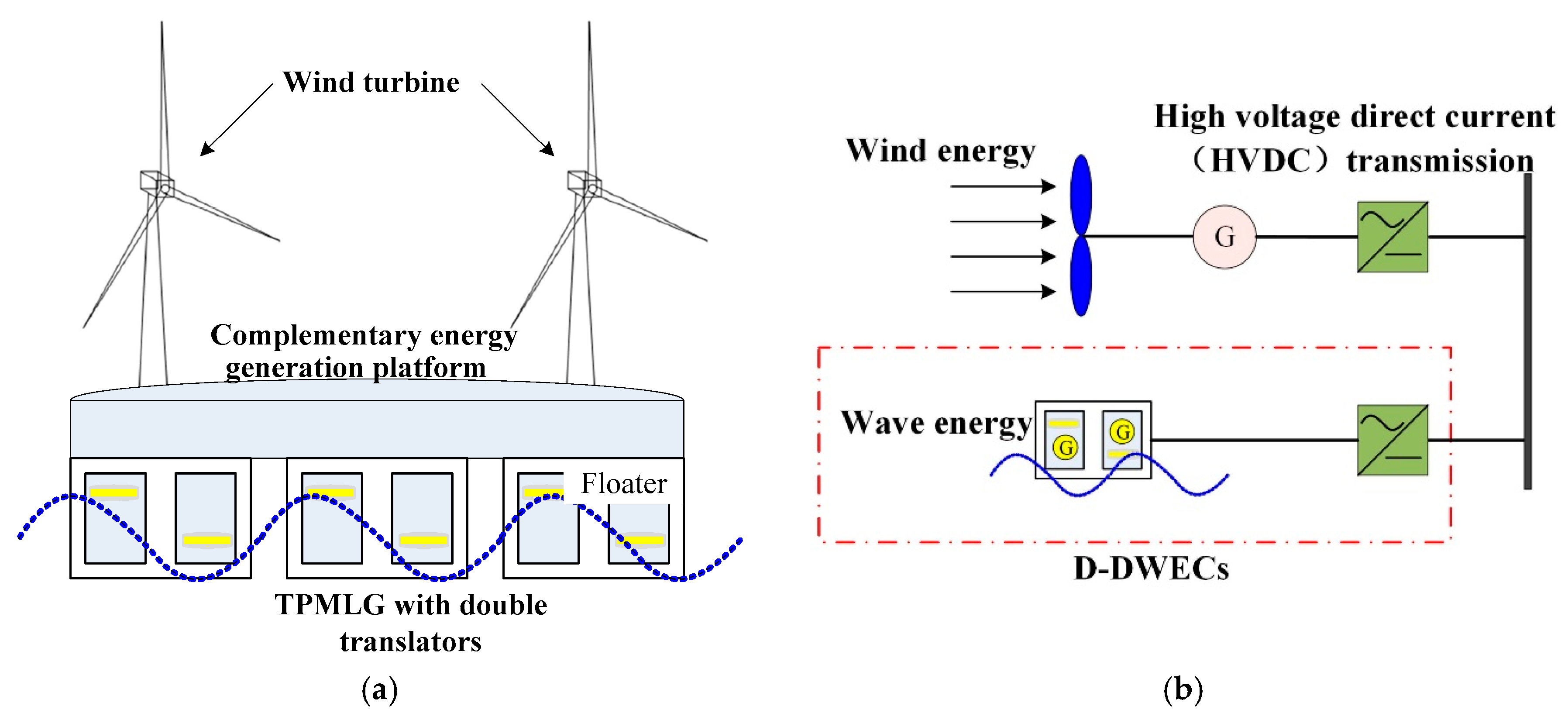
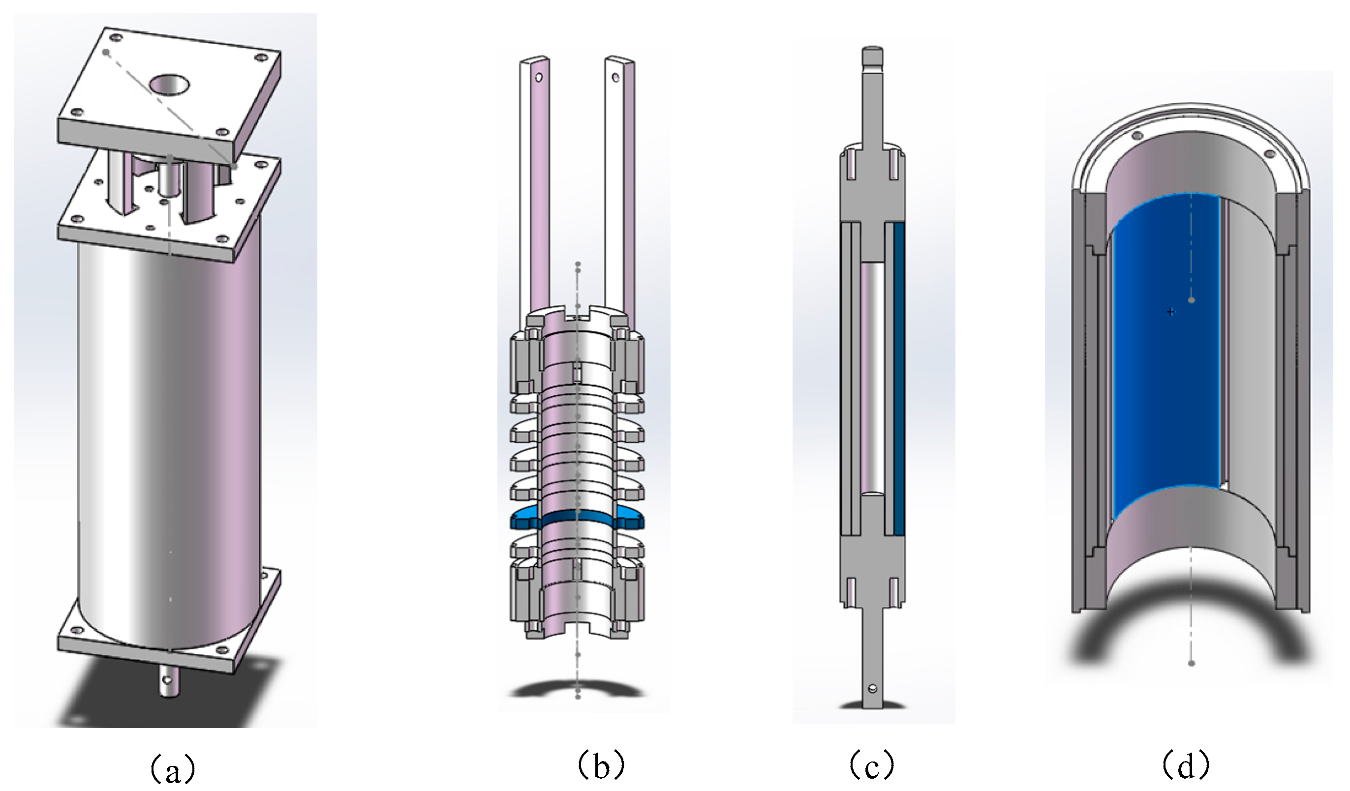
2. Platform Configuration and Generator Structure

2.1. Platform Configuration

Figure 1a shows the wind and wave complementary energy generation platform that consists of the TPMLGs with double translators, the wind turbines, floaters, and power processing modules. Figure 1b shows the schematic of power take-off (PTO) using high voltage direct current (HVDC) transmission system. In the D-DWECs of the platform, the two translators of TPMLGs are connected with the floaters under the platform. With the synchronous movement of the two translators driven by the sea wave, the EMF of the TPMLG can be obtained by Faraday’s law of magnetic induction in Equation (1):
e = N d Ψ d t = N B Z d s d t = 2 π N B Z d R d t
where N is the number of turns of the winding, ψ is the flux linkage of the winding and BZ is the radial air gap flux density.

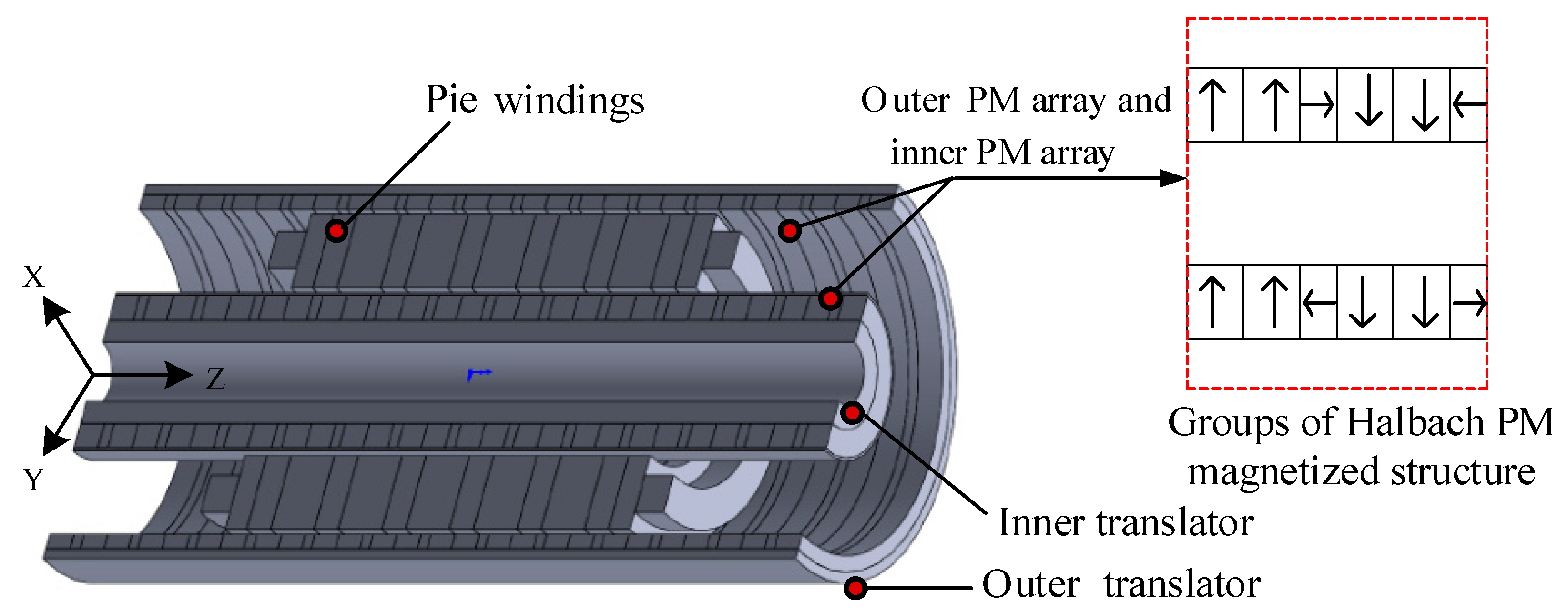
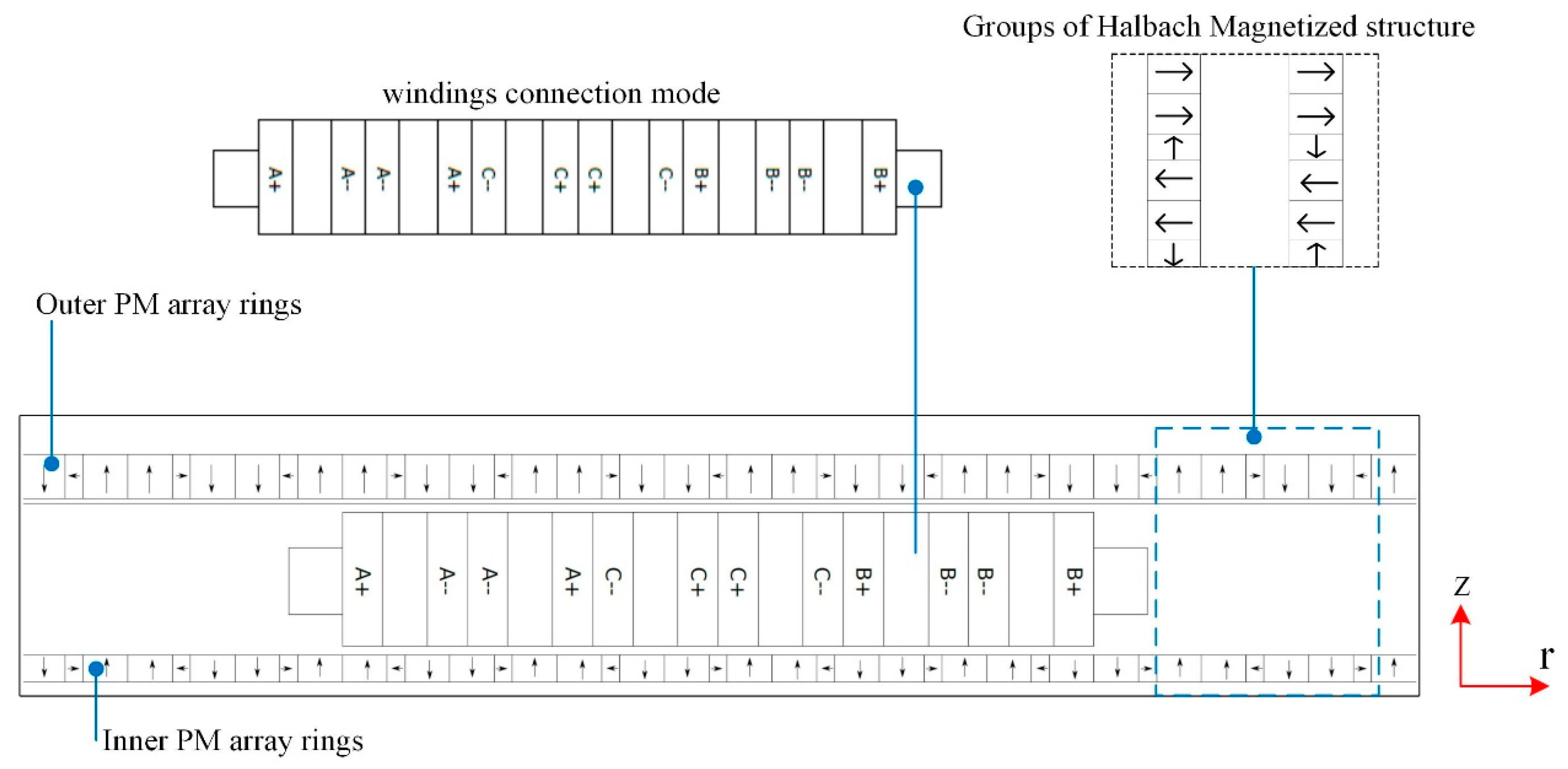
2.2. Generator Configuration

Firstly, according to the average wave height and wave speed, the motion stroke of the generator is determined, and then, the internal structure of the generator is determined according to the electromagnetic load, such as stator length, translator length, PM thickness, PM Pole pitch, Stator radius, length of air gap, the number of turns of the coils and so on. The basic parameters of TPMLG with double translators are listed in Table 1. Finally, the parameters of the generators are analyzed and optimized according to the Genetic Algorithm.
Figure 2 shows the optimized structure of the TPMLG with double translators applied in the complement energy generation platform. The TPMLG consists of one stator with the pie windings, a toothless structure and two translators (the inner translator and the outer translator) made of steel, on which the groups of Halbach PM magnetized structure of neodymium iron boron (NdFeB) are mounted on. The two structure rings are placed outside the inner translator and inside the outer translator, respectively.
As we known according to the literature [13], Halbach PM arrays has the characteristics of single side magnetic accumulation. In this paper, the double translators with groups of Halbach PM magnetized structure are optimized to increase the magnetic energy density of TPMLG. Then, the detailed analyses of the magnetic field distribution, air gap flux density of inner translator and outer translator, the detent force fluctuation, and EMF at constant velocity or sine speed conducted by FEM are based on the TPMLG model.

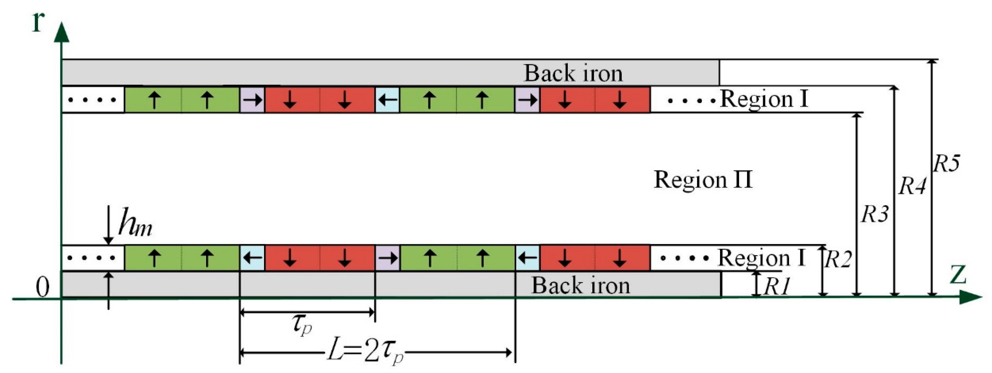
2.3. Groups of Halbach PM Magnetized Structure

In 1979, Halbach, an American scholar, discovered the special magnetizing structure of PM when he accelerated his electronic experiments, which are now called Halbach PM arrays [14]. It arranges PMs with different magnetization directions in a certain order, so that the magnetic flux density on one side of the PM array is enhanced significantly, while that on the other side is weakened. Therefore, a magnetic field with sinusoidal distribution can be obtained.
The angle of Halbach PM arrays of the TPMLG proposed is calculated by the Equation (2):
θ i = ( 90 θ ( t + 1 ) ) ( 90 θ ( t ) ) = 180 / n
where θi is the angle between the adjacent magnet, n is the number of per pole, θt and θ(t + 1) are the magnetizing angles of the t th and (t + 1) th and t is integer. The magnetization of the ith magnet can be obtained by the Equation (3) and Equation (4), where Mr is radial component of magnetization, and Mz is axial component of magnetization:
M z ( i ) = M cos [ θ i ± ( i 1 ) 360 2 n ]
M r ( i ) = M sin [ θ i ± ( i 1 ) 360 2 n ]
Figure 3 shows the analysis the results for the four PM arrays structure model only by FEM. In the condition of n = 1, the value of θi is 180°, as are shown in Figure 3(a1,a2, b1,b2), where Figure 3a1 is radial magnetization PM structure and Figure 3b1 is axial magnetization PM structure. In the condition of n = 2, the value of θi is 90°, Figure 3c1 is PM structure and Figure 3c2 is the flux density curve. In the condition of n = 3, the value of θi is 60°, Figure 3d1 is PM structure and Figure 3d2 is the flux density curve.
By applying Halbach PM arrays in TPMLG, the peak of gap flux density is increased and better sinusoidal waveforms can be obtained. Therefore, it can reduce the yoke thickness of TPMLG, decrease the volume and weight of TPMLG and improve the power of TPMLG. Moreover, with the refinement of magnetizing direction, the processing technic for Halbach PM arrays will be more demanding.
Figure 4 shows the THD percentage composition of EMF when the four PM arrays structures are applied in the linear generator with single translator by Fourier analysis. The generator has the same structure and parameters as the TPMLG with double translators in the matter of the stator and windings. The operation velocity of the generator in the four case is 0.4 m/s, and the partial stator parameters of the TPMLG with single translator are listed in Table 1. From Figure 4, THD for n = 3 Halbach PM structure is minimum in the four structure.
The groups of Halbach magnetized structure and windings connection mode of the TPMLG with two translators are shown in Figure 5. As can be seen, the magnetization pattern of the two structure rings is different, the axial magnetization direction of the inner PM array rings and the outer PM array rings is opposite and the radial magnetization direction of the inner PM array rings and the outer PM arrays rings is same. The magnetization arrangement of above can increase the radial air gap flux density, and decrease the axial air gap flux density.

3. Generator Magnetic Field Analysis

3.1. Assumptions

The TPMLG with double translators is symmetric structure along the z-axis, and half of the structure is selected as the analysis area. As shown in Figure 6, the region consists of region I and region II. Region I is groups of Halbach PM magnetized structure rings on the two translators, region II is consists of air gap and the windings and the symbolic meaning in Figure 6 is listed in Table 1.
In order to establish magnetic field equation, the following four assumptions are made in the analysis process:
The length of the TPMLG in the axial direction is infinite; thus, the magnetic field of the generator can be considered as symmetric along the translator. However, there is a relationship between the edge-end effect and the length of the stator; the edge-end effect is considered in this study.
The slotless structure topology is applied in this TPMLG, and the permeability of translator core and stator core is infinite.
The material NdFeB is used in the TPMLG, the recovery curve almost coincides with the demagnetization curve and the magnet is magnetized uniformly.
For the analysis process is in the matter of no-load, the magnetic field generated by the windings is not considered.

3.2. Magnetic Field Governing Equations

In Figure 7, region I is filled PM with rare-earth magnetic material, and region II consists of air and coil space with a relative permeability of 1.0.
Assuming that the windings current is zero, the governing equations of magnetic field in terms of A(θ) in cylindrical coordinators are presented as follows:
2 A ( θ ) Z 2 + r [ ( 1 r r ( r A ( θ ) ) ) ] = 0               region   II
2 A ( θ ) Z 2 + r [ ( 1 r r ( r A ( θ ) ) ) ] = - μ 0 ( × M )       region   I
where M is the intensity magnetization vector, and μ0 is the permeability of free space, and A(θ) is a function of r and z.
The calculation process of electromagnetic field model is to solve differential equations, such as solving Equation (5) and Equation (6) in differential boundary conditions by this model above. Therefore, the boundary conditions are necessary to determine the specific solution of the calculation region. The boundary conditions in the model to be satisfied by Equation (7) as follows:
B I Z | r = R 4 = μ 0 M Z             B I Z | r = R 1 = μ 0 M Z                 B II r | r = R 3 = B I r | r = R 3 B II r | r = R 2 = B I r | r = R 2       H II Z | r = R 3 = H I Z | r = R 3       H II Z | r = R 2 = H I Z | r = R 2

4. Analysis of Performance

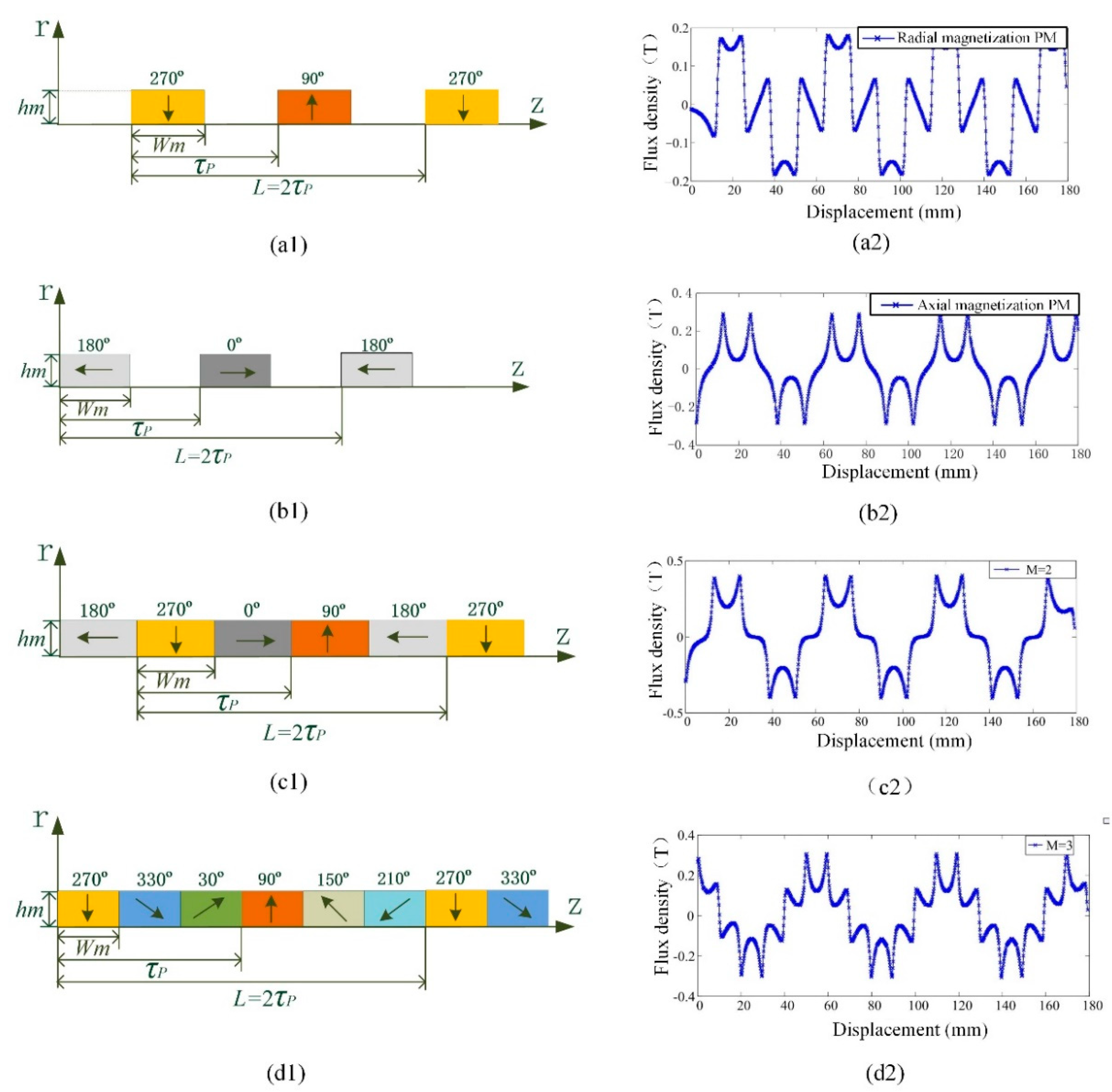
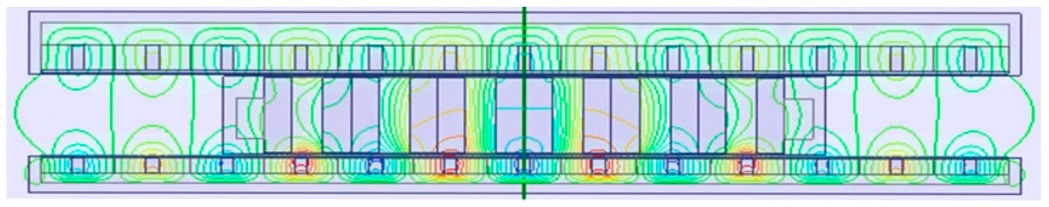
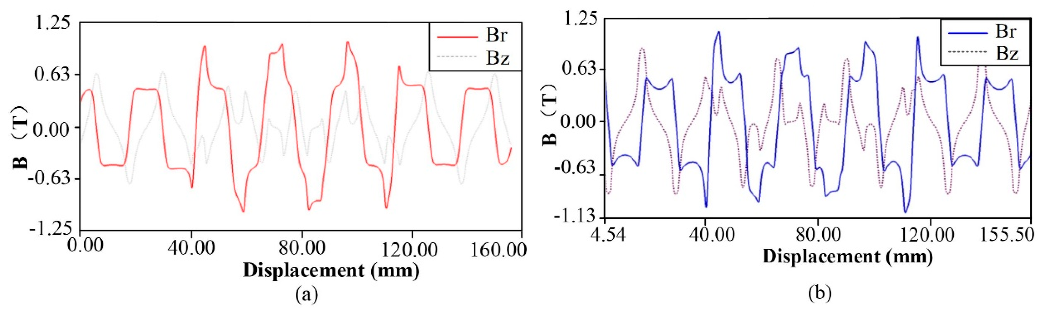
4.1. Magnetic Field Distribution

Figure 7 depicts the static magnetic field distribution of the TPMLG with two translators in no-load operation. Based on the TPMLG topology and finite element method (FEM), the air gap flux density between the inner translator and the outer translator are calculated in Figure 8. It shows the air gap flux density of the inner translator, and that the peak value of radial flux density can reach 1.23 T in Figure 8a. Figure 8b shows that the peak value of radial flux density in the outer air gap can reach 1.21 T. It is observed that the groups of Halbach magnetized structure can increase the radial flux density and decrease the axial flux density in TPMLG with double translators.

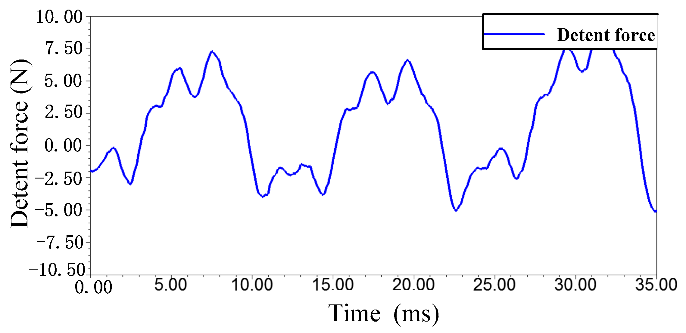
4.2. Analysis of Detent Force

There are two main reasons for the detent force in the TPMLG: one is the edge-end force formed by the interaction between the edge teeth of stator and the magnets, the other is cogging force formed by the interaction between the middle teeth of stator and the magnets of translator [15,16]. The detent force seriously affects the performance of TPMLG, especially in the matter of low velocity. It makes the system oscillated and decrease the stability of the system. In reference [17], the authors adopted the structure of no PM at the end sides of the stator and the translator in the tubular primary-PM linear generator, and the edge-end force is at a minimum. In reference [18], the authors proposed a one-tooth model to reduce the cogging force, and the method of a one-tooth model is suitable for the analysis of tooth motors.
In this paper, for the axial magnetic flux density of TLPMG is reduced by using double translators with PM structure in the design, the detent force is decreased. Moreover, a reasonable design of the stator length of linear generator can also reduce the detent force of the generator. In this paper, considering the moving distance of the low-speed D-DWECs and the design requirements of the experimental platform, the stator length of linear generator is optimized to be 84 mm. The detent force of the TPMLG with two translators is reduced by optimizing structural parameters of the two-side Halbach PM arrays. The groups of Halbach PM magnetized structure are proposed as shown in Figure 4. The total width of the radial magnetization PM is 8 mm, which is divided into the two parallel PM rings of 4 mm. The width of the axial magnetization PM ring is 1.6 mm.
In this work, two translator structures and the groups of Halbach PM magnetized structures are applied in this TPMLG. In Figure 9, the ripple peak of the detent force is decreased to 7.0 N. It can improve the stability of the TPMLG at low speed effectively and increase the energy conversion efficiency of D-DWECs.
Figure 10 shows that ripple peak of the detent force is reduced to 7.0 N in the condition of the groups of Halbach PM magnetized structure. Comparing with the radial magnetization PM, the ripple peak of the detent force can be reduced by 50%.

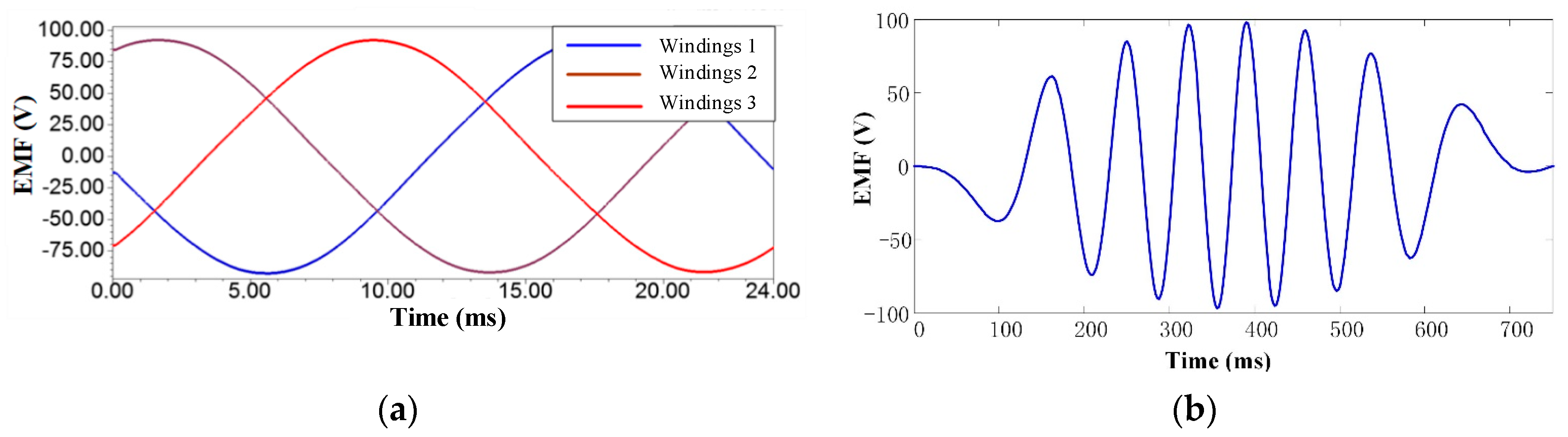
4.3. No-Load Performances

When the TPMLG runs in the condition of no-load, and the velocity of the translator is 0.8 m/s, the dynamic characteristics of the generator is analyzed. For the pole pitch of the magnet is 9.6 mm, f = v/2τ, the period of EMF is 24 ms. Based on FEM, the three-phase EMF waveform of the generator is obtained in Figure 11a, it shows that the peak value of EMF is 95 V. When the velocity of the translator is a sine velocity of 0.8 sin (4πt/3) m/s, the EMF waveforms of the TPMLG is obtained in Figure 11b. It shows that an EMF peak of 98 V is obtained.

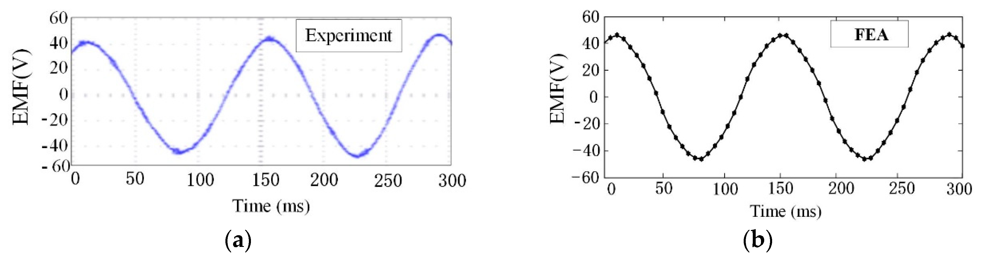
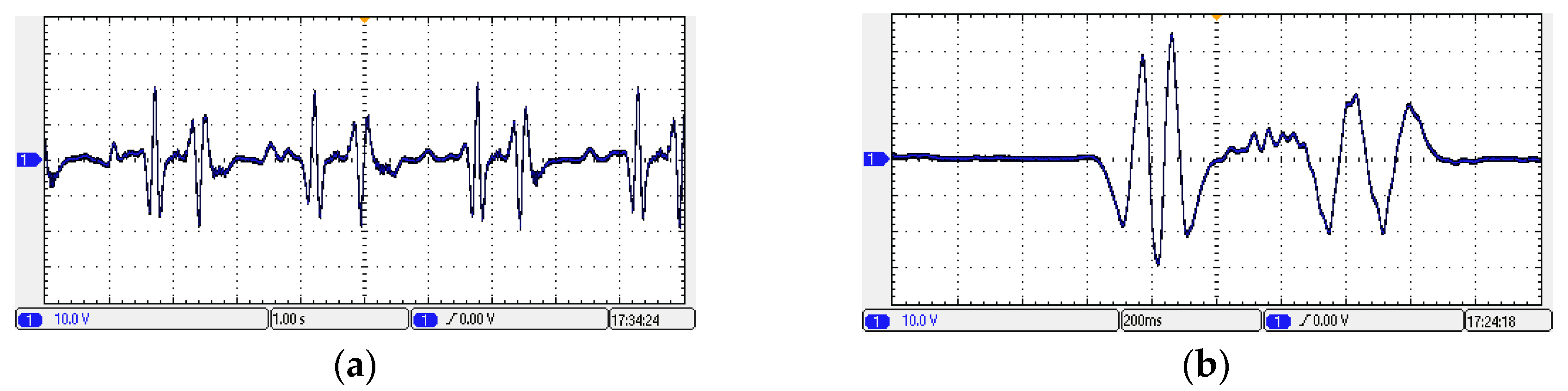
5. Experiment and Comparative Analysis

In order to test the validity of the TPMLG with double translators, this study adopts a tubular PM linear generator with single translator, as shown in the Figure 12. The generator has the same structure and parameters as the TPMLG with double translators in the matter of the stator and windings. And partial stator parameters of the TPMLG with single translator are listed in Table 1.

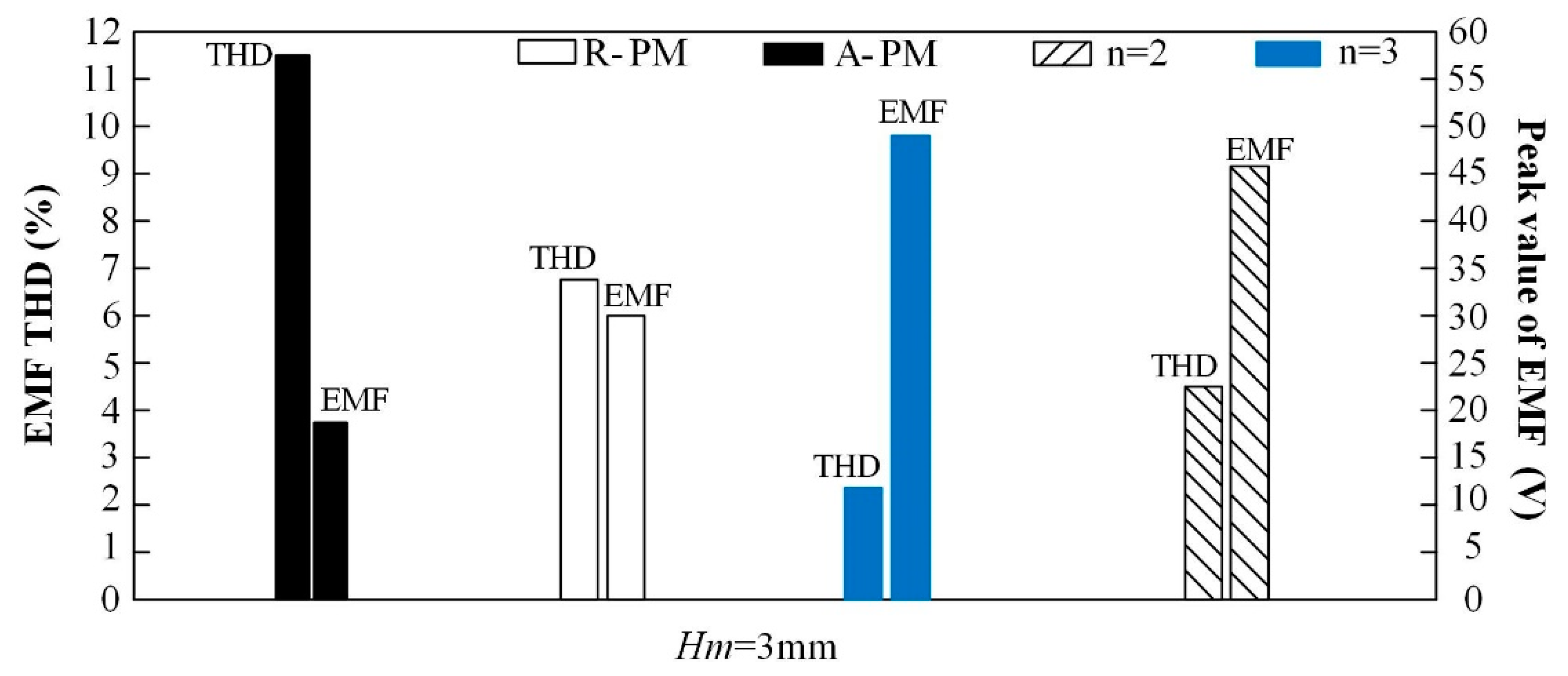
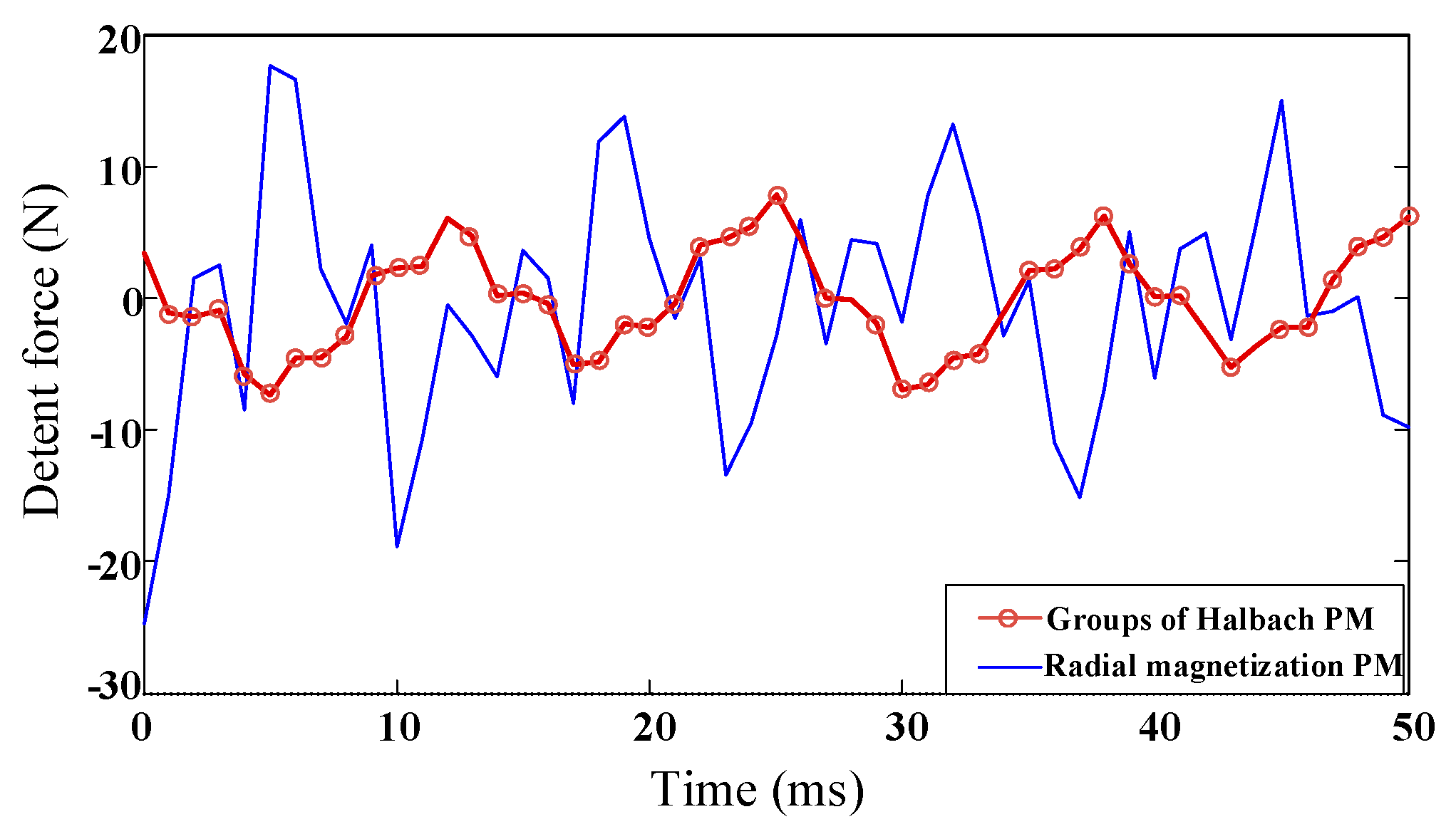
5.1. Comparative Analysis

Figure 13 shows that the TPMLG with double translators comprises the stator, the inner translator and the outer translator. In the process of comparison and analysis, the linear running speed of both motors is 0.4 m/s.
Table 2 shows the performances consisting of EMF, air gap magnetic density peak, detent force and efficiency for the two generators. It can be seen from Table 2 that the EMF peak of linear generator with single translator is 45 V less than 72 V of TPMLG with double translators. The peak magnetic density of linear generator with single translator is 0.72 T, while that of TPMLG with double translators is 1.20 T. The detent force amplitude of linear generator with single translator is 45 N larger than 7.5 N of TPMLG with double translators. The maximum efficiency of linear generator with single translator is 77% less than 87.2% of TPMLG with double translators.
The analysis results show that the TPMLG with double translators with high radial magnetic flux density, high conversion efficiency and low detent force fluctuation are significant to meet better performance for the wind and wave complementary energy generation platform.

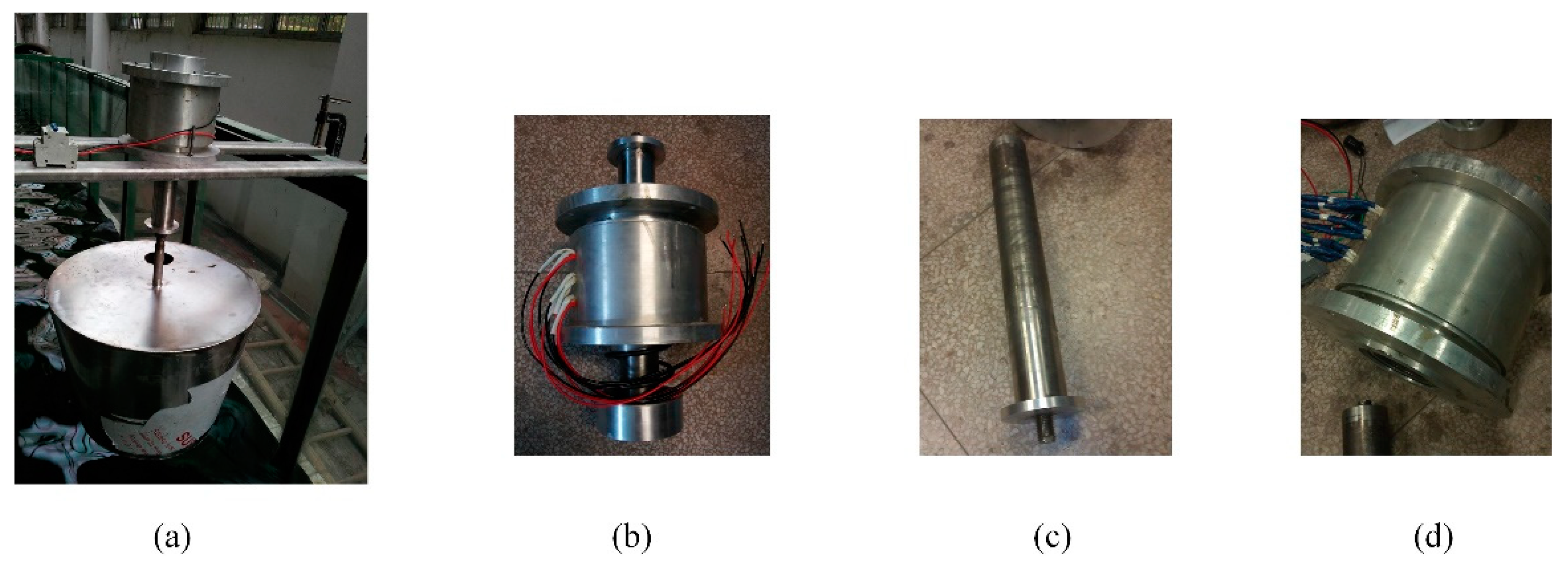
5.2. Experiment Analysis

When the generator with single translator runs at a constant velocity, the test results of EMF is shown in Figure 14. When the constant velocity is 0.4 m/s, the peak value of 40 V can be obtained by experiment in Figure 14a, and the peak value of 45 V can be obtained by FEM in Figure 14b.
Figure 12a shows the experimental platform of D-DWECs. It consists of a TPMLG with single translators, a support structure, measuring instrument, a hollow floater, linkage and so on. Figure 15 shows the output voltage waveform in no load for the experimental platform of the D-DWECs. From Figure 15a, when wave height of input wave is 0.15 m and wave period of input wave is 1.5 s, the peak voltage of 35 V can be obtained. From Figure 15b, when the wave height of input wave is 0.2 m and the wave period of input wave is 2 s, the peak voltage of 22 V can be obtained.
According to the results of the experimental platform of D-DWECs above, the tubular PM linear generator with single translators can convert wave energy into electric energy with D-DWECs. However, the peak value of the output voltage is low in low-speed operation; moreover, the waveform of the output voltage has a lot of harmonics. According to the theoretical calculation and comparative analysis of the two linear generators, the proposed TPMLG with double translators and groups of Halbach magnetized structure has some advantages in terms of detent force, high magnetic energy density and high voltage amplitude.

6. Conclusions

This paper proposed a TPMLG with double translators applied in wind and wave complementary energy generation platform. The performance of TPMLG with double translators is assessed by magnetic field analysis model and axi-symmetrical transient FEM. Three conclusions can be drawn by the analysis results of the model analysis and test as follows:
(1)
The groups of Halbach PM magnetized structure can increase the radial flux density. Magnetic energy density of the TPMLG is increased by optimizing the structure of the two translators.
(2)
The groups of Halbach PM magnetized structure can decrease the axial flux density, and the detent force in the TPMLG is reduced. Thus, the stability and conversion efficiency of the systems is obviously improved.
(3)
The TPMLG with double translators have the advantages of high flux density, high output efficiency and low detent force fluctuation. Moreover, better performance of the TPMLG is obtained by the D-DWECs in wind and wave complementary energy generation platform.

Author Contributions

All the authors offer the best efforts to ensure that the paper becomes qualified for publishing. H.Y. provided test platform, J.Z. designed and supervised the work. Z.S. completed the simulations and experiments.

Funding

This work was supported by the Postdoctoral Foundation of China under Grant 2015M570396, Jiangsu Province Natural Science Foundation of Youth under Grant BK20150115, and Natural Science Foundation incubation project under Grant JIT-fhxm-201702.

Conflicts of Interest

The authors declare no conflict of interest.

References

  1. Melikoglu, M. Current status and future of ocean energy sources: A global review. Ocean Eng. 2018, 148, 563–573. [Google Scholar] [CrossRef]
  2. Drew, B.; Plummer, A.R.; Sahinkaya, M.N. A review of wave energy converter technology. Proc. Inst. Mech. Eng. Part A J. Power Energy 2009, 223, 887–902. [Google Scholar] [CrossRef] [Green Version]
  3. Polinder, H.; Mattia, S. Wave energy converters and their impact on power systems. In Proceedings of the International Conference on Future Power Systems, Amsterdam, The Netherlands, 16–18 November 2005; pp. 1–9. [Google Scholar]
  4. Ozkop, E.; Altas, I.H. Control, power and electrical components in wave energy conversion systems: A review of the technologies. Renew. Sustain. Energy Rev. 2017, 67, 106–115. [Google Scholar] [CrossRef]
  5. Ahn, K.K.; Truong, D.Q.; Tien, H.H.; Yoon, J., II. An innovative design of wave energy converter. Renew. Energy 2012, 42, 186–194. [Google Scholar] [CrossRef]
  6. Gao, Y.; Shao, S.; Zou, H.; Tang, M.; Xu, H.; Tian, C. A fully floating system for a wave energy converter with direct-driven linear generator. Energy 2016, 95, 99–109. [Google Scholar] [CrossRef] [Green Version]
  7. Brekken, T.K.A.; von Jouanne, A.; Han, H.Y. Ocean wave energy overview and research at Oregon State University. In Proceedings of the Power Electronics and Machines in Wind Applications, Lincoln, NE, USA, 24–26 June 2009; IEEE: New York, NY, USA, 2009. [Google Scholar]
  8. Ekström, R.; Ekergård, B.; Leijon, M. Electrical damping of linear generators for wave energy converters—A review. Renew. Sustain. Energy Rev. 2015, 42, 116–128. [Google Scholar] [CrossRef]
  9. Polinder, H.; Mecrow, B.C.; Jack, A.G.; Dickinson, P.G.; Mueller, M.A. Conventional and TFPM Linear Generators for Direct-Drive Wave Energy Conversion. IEEE Trans. Energy Convers. 2005, 20, 260–267. [Google Scholar] [CrossRef]
  10. Prudell, J.; Stoddard, M.; Amon, E.; Brekken, T.K.A.; Jouanne, A. A permanent-Magnet Tubular Linear Generator for Ocean Wave Energy Conversion. IEEE Trans. Ind. Appl. 2010, 46, 2392–2400. [Google Scholar] [CrossRef]
  11. Mueller, M.A. Electrical generators for direct drive wave energyconverters. IET Gener. Transm. Distrib. 2002, 149, 446–456. [Google Scholar] [CrossRef]
  12. Leijon, J.; Sjölund, J.; Ekergård, B.; Boström, C.; Eriksson, S.; Temiz, I.; Leijon, M. Study of an Altered Magnetic Circuit of a Permanent Magnet Linear Generator for Wave Power. Energies 2018, 11, 84. [Google Scholar] [CrossRef] [Green Version]
  13. Shen, Y.; Zhu, Z.Q. Analysis of Electromagnetic Performance of Halbach PM Brushless Machines Having Mixed Grade and Unequal height of Magnets. IEEE Trans. Magn. 2013, 49, 1461–1469. [Google Scholar] [CrossRef]
  14. Halbach, K. Strong rare-earth cobalt quadrupoles. Bull. Am. Phys. Soc. 1979, 26, 3882–3884. [Google Scholar] [CrossRef]
  15. Feng, N.; Yu, H.; Hu, M.; Huang, L.; Shi, Z. A Study on a Linear Magnetic-Geared Interior Permanent Magnet Generator for Direct-Drive Wave Energy Conversion. Energies 2016, 9, 487. [Google Scholar] [CrossRef] [Green Version]
  16. Youn, S.W.; Lee, J.J.; Yoon, H.S.; Koh, C.S. A new cogging-free permanent-magnet linear motor. IEEE Trans. Magn. 2008, 44, 1785–1790. [Google Scholar] [CrossRef]
  17. Huang, L.; Yu, H.; Hu, M.; Liu, C.; Yuan, B. Research on a Tubular Primary Permanent-Magnet Linear Generator for Wave Energy Conversions. IEEE Trans. Magn. 2013, 49, 1917–1920. [Google Scholar] [CrossRef]
  18. Zhou, S.; Yu, H.; Hu, M.; Jiang, C.; Hao, L. Reduction of Cogging Force in a Linear Flux-Switching Permanent-Magnet Brushless AC Machine for Direct-Drive Applications. IEEE Trans. Magn. 2011, 47, 3252–3255. [Google Scholar] [CrossRef]
Figure 1. The complementary energy generation platform: (a) the configuration of platform; (b) the configuration of power take-off (PTO).
Energies 12 04606 g001
Figure 2. Structure of TPMLG with double translators.
Energies 12 04606 g002
Figure 3. PM arrays structure model and flux density curve: (a1) radial magnetization PM structure, (b1) axial magnetization PM structure, (c1) n = 2 Halbach PM structure, (d1) n = 3 Halbach PM structure, (a2), (b2), (c2) and (d2) are the gap flux densities of Figure 3a1, Figure 3b1, Figure 3c1 and Figure 3d1, respectively.
Energies 12 04606 g003
Figure 4. THD and EMF of the linear generator with the four PM structure.
Energies 12 04606 g004
Figure 5. Two-dimensional (2D) mode with groups of Halbach PM magnetized structure and windings connection.
Energies 12 04606 g005
Figure 6. Analysis region with groups of Halbach PM magnetized structure.
Energies 12 04606 g006
Figure 7. Magnet field distribution of generator.
Energies 12 04606 g007
Figure 8. Air gap flux density curves of generator: (a) air gap flux density of inner translator and (b) air gap flux density of outer translator.
Energies 12 04606 g008
Figure 9. Detent force of the TPMLG with double translators.
Energies 12 04606 g009
Figure 10. Detent force of TPMLG with groups of Halbach PM magnetized structure and radial magnetization PM.
Energies 12 04606 g010
Figure 11. Electromotive force (EMF) waveforms of the TPMLG: (a) at constant velocity (b) at sine velocity.
Energies 12 04606 g011
Figure 12. Tubular PM linear generator with single translators for comparison: (a) experimental platform of D-DWECs; (b) prototype; (c) translator; (d) stator and windings.
Energies 12 04606 g012
Figure 13. Proposed tubular linear PM generator (TPMLG) with double translators for D-DWECs: (a) three-dimensional (3D) schematic; (b) stator; (c) inner translator; (d) outer translator.
Energies 12 04606 g013
Figure 14. EMF waveform of the generator with single translator: (a) in the experiment, (b) with the finite element method (FEM).
Energies 12 04606 g014
Figure 15. Output voltage waveform of experimental platform of D-DWECs. (a) Wave height is 0.15 m, wave period is 1.5 s. (b) Wave height is 0.2 m, wave period is 2 s.
Energies 12 04606 g015
Table 1. Parameters of the stator and the two translators.
SymbolItemValue
HgAir gap length1 mm
LSStator length84 mm
LTTranslator length156 mm
hmPM thickness3 mm
τpPM Pole pitch9.6 mm
R1Back iron thickness2 mm
R2Inner translator radius5 mm
R3Stator radius23 mm
R5Outer translator radius28 mm
NTurns of coils280
Table 2. Performance data of the two generators.
Motor TypePeak Value of EMF (V)Peak Value of B (T)Minimum Value of F (N)Maximum of η
Generator with single translator450.724577%
TPMLG with double translators721.207.5087.2%

