Article

New Curved Reflectors for Significantly Enhanced Solar Power Generation in Four Seasons †

1
School of Electrical Engineering, KAIST, Daejeon 34141, Korea
2
School of Integrated Technology, GIST, Gwangju 61005, Korea
*
Author to whom correspondence should be addressed.
This paper is an extended version of our paper published in 2017 IEEE Workshop on Control and Modeling for Power Electronics (COMPEL), Stanford, CA, USA, 9–12 July 2017; pp. 1–6.
Energies 2019, 12(23), 4602; https://doi.org/10.3390/en12234602
Submission received: 4 October 2019 / Revised: 17 November 2019 / Accepted: 1 December 2019 / Published: 3 December 2019
(This article belongs to the Section A2: Solar Energy and Photovoltaic Systems)

Abstract

:
A new curved-type reflector for solar power generation is proposed. By adopting the curved-type reflector between consecutive solar panel arrays, all incoming sunlight can be utilized and thus, the generated power is significantly increased. Furthermore, the proposed curved-type reflector can be generally used in four seasons regardless of the altitude or angle of the installation environment. The optimum design rule for the curved-reflector, comparing to a plane-type reflector, is completely developed in this paper. A new solar cell configuration best fit for the proposed curved-reflector is also provided. Experimental results showed that the curved-type reflector improves the spatial average solar power by 61% compared to no reflector case, which is even 11% higher than the plane-type reflector. Reflectors, especially curved-type reflectors, are found to be one of promising solutions for highly efficient solar power generation.

1. Introduction

Solar power is rapidly replacing existing power sources such as fossil fuels in an effort to address issues mostly related to global climate change, economy, and safety [1,2,3,4,5,6,7,8]. However, solar power has a few limitations, including large fluctuations of the output power depending on weather conditions and angle of sunlight incidence as well as low power generation efficiency [8,9]. Many studies have attempted to improve the efficiency of solar power generation by: improving solar cell efficiency [10], a maximum power point tracking (MPPT) operation method [11,12], a cooling system for solar panels [13], and, optimization of photovoltaic inverters [14,15,16]. However, the impacts of these methods on efficiency have remained limited due to the seasonal-, time- or weather-varying intensity levels of sunlight incidence on the solar panels.
As the highest elevation angle of the sun is high in summer and low in winter, the seasonal efficiency of the fixed-type solar panel system varies depending on the installation angle of the panels. Generally, in solar power generation, solar panels are arranged consecutively, as shown in Figure 1. However, if two or more panels are installed, additional efficiency loss can arise due to shadows created by the variation of the elevation angle of the sun, especially in winter. Thus, the distance between neighboring panels is often elongated to minimize the efficiency decrement due to the shadows, as shown in Figure 2a. However, this elongated distance increases investment costs, such as land and management costs. Furthermore, it causes waste of sunlight in summer when the unused area is widened, as shown in Figure 2b.
In an effort to overcome these problems, a bifacial solar panel that uses both sides of the panel was suggested [17,18]. Although it enables the use of the reflected sunlight from the ground or the water surface, the amount of increased power generation is merely about 10%. Therefore, using a reflector with high reflectivity is generally more desirable to increase the efficiency of solar power generation.
Thus, reflectors are installed between neighboring panels, as shown in Figure 2c, to increase the solar power efficiency by nearly 50% in summer compared to no reflector case [19,20,21,22,23,24]. However, some reflected sunlight cannot enter the solar panel when the elevation angle of the sun is high.
A curved-type reflector, also known as a parabolic-shaped collector, is often used to reflect the incident sunlight onto its focal line, which raises the temperature of the fluid inside the convergence point [25]. However, the curved-reflector has never been used to increase the generated power by consecutive solar panel array. As reflectors are one of the highly promising solutions for an additional efficiency increase in solar power generation, its potential contributions and limitations should be studied in more detail. Not enough analysis and design guidelines on the reflector type have been proposed so far.
In this paper, a new solar panel array using a curved-type reflector by which all incoming sunlight can enter the solar panel regardless of the elevation angle of the sun is proposed, as shown in Figure 2d. Efficiency comparisons with no reflector and a plane-type reflector are provided with explicit analysis results [26].

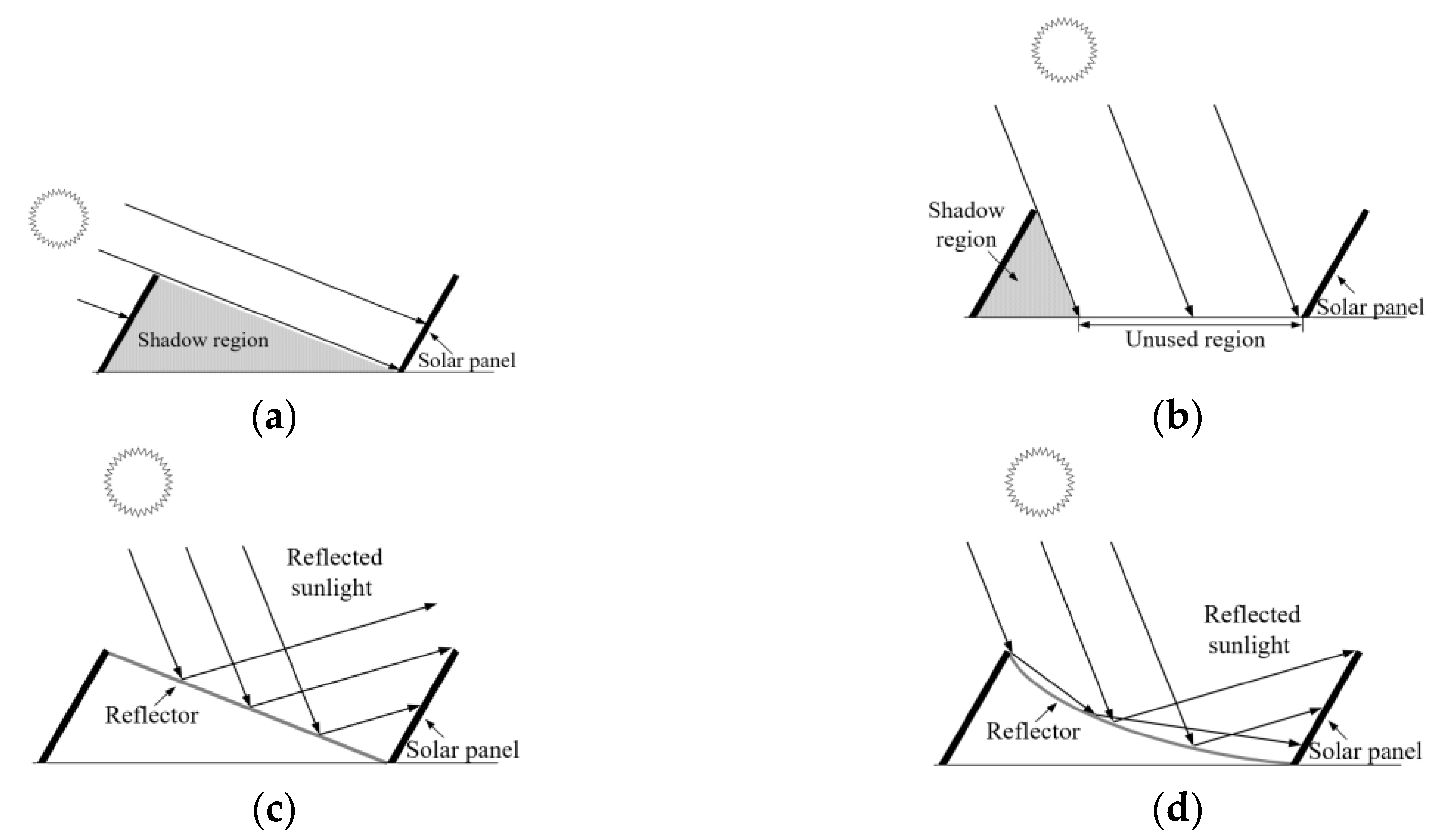
2. Analysis of the Incidence Power for Different Reflector Types

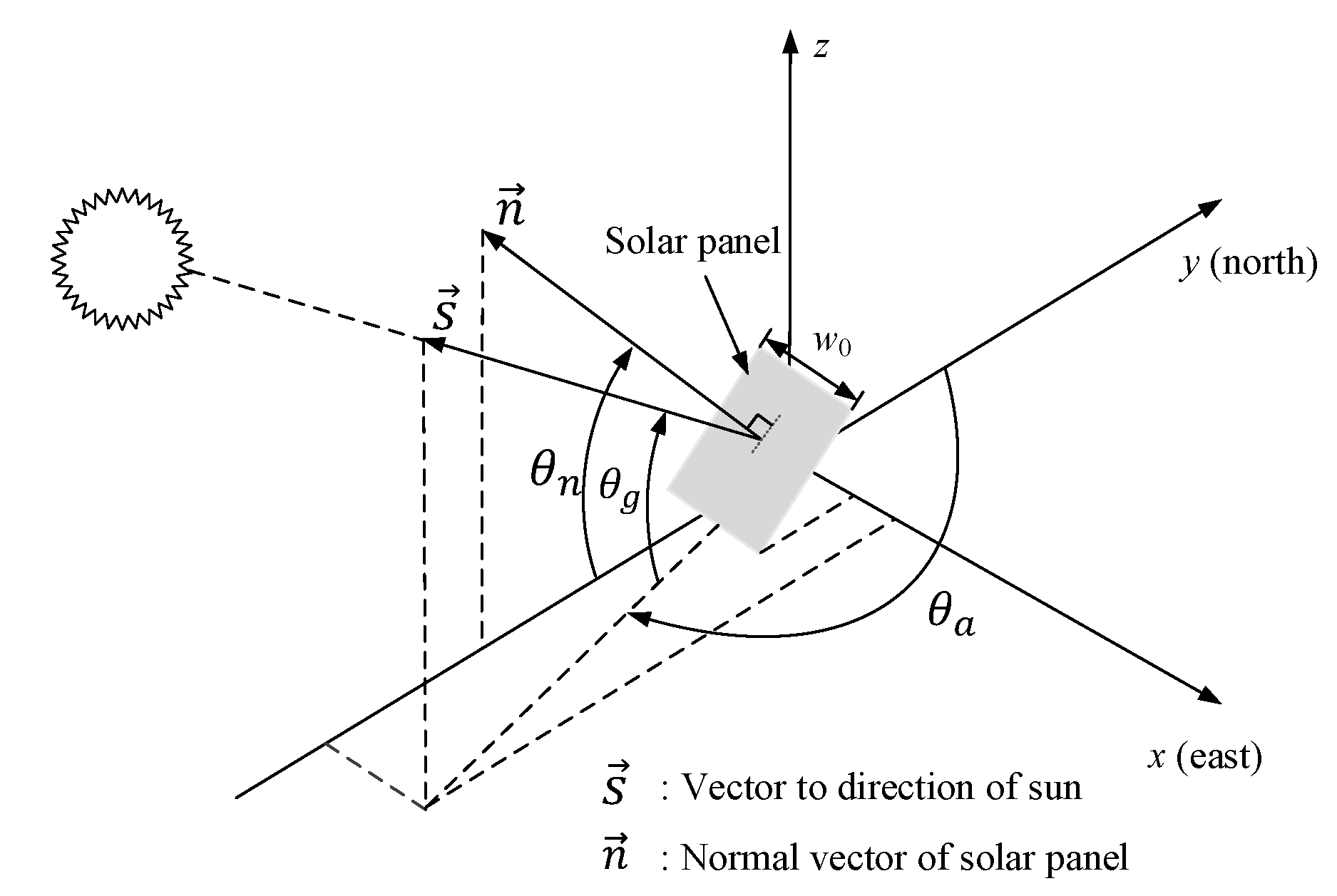
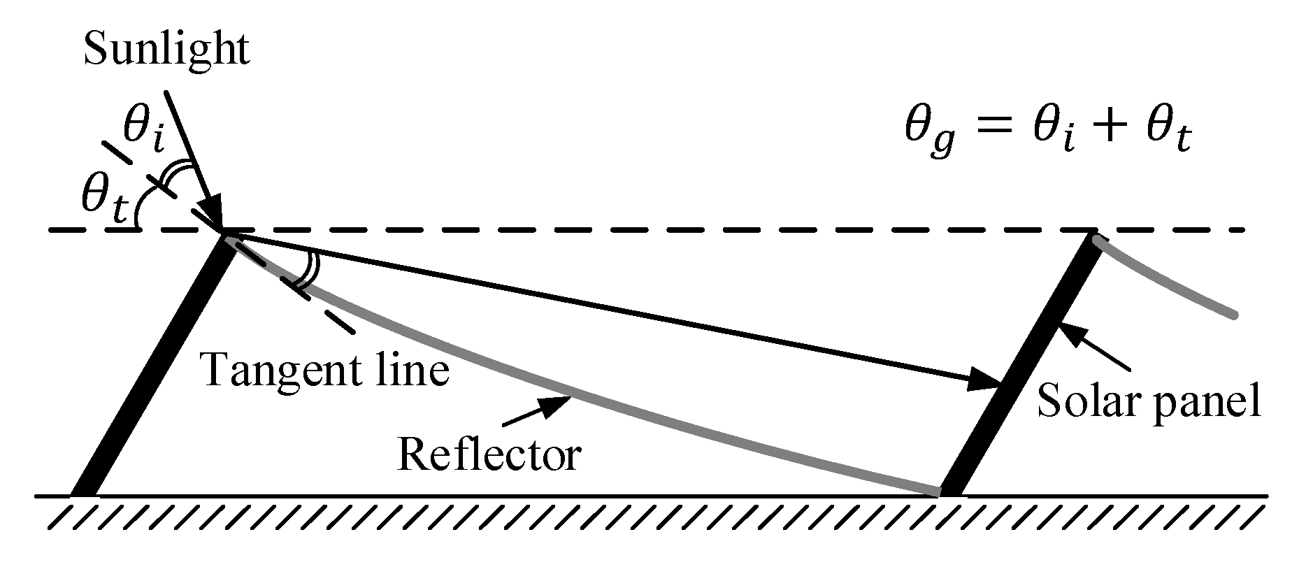
2.1. Effective Amount of Sunlight Normal to a Panel

In this section, the output power of each type of reflector is fully analyzed. It is assumed that the solar panel is installed to face south (in the northern hemisphere) for all reflectors. In solar power generation systems, the generated power is mainly affected by three factors: the elevation angle of the sun θ g , the azimuth angle of the sun measured from the north θ a , and the shadow caused by neighboring panels, as shown in Figure 3. Note that θ n is the angle of the normal vector of the panel and s and n are the vectors indicating the direction of the sun from the panel and the normal vector of the panel, respectively.
The average power generated by a solar panel at a certain elevation and azimuth angle of the sun can be expressed as follows:
P o u t ( θ g , θ a ) = p 0 w 0 R e ( θ g , θ a ) L e ( θ g )
where p 0 , w 0 , R e ( θ g , θ a ) , and L e ( θ g ) correspondingly represent the solar power per unit area of the panel, the panel width, the coefficient of the effective amount of sunlight normal to the panel, and the effective length that determines the amount of sunlight entering into the panel. Therefore, given the type and the size of the solar panel, the photovoltaic power from the solar panel will be determined by two factors: R e ( θ g , θ a ) , which is the ratio of the sunlight that intersects the panel perpendicularly, and L e ( θ g ) , which is varied by the reflector types and θ g for a given panel installation environment.
Figure 3 shows the solar panel and incident sunlight in vector form at an arbitrary date and time. R e ( θ g , θ a ) is expressed as the inner product of two vectors s and n as follows:
s = ( cos θ g sin θ a , cos θ g cos θ a , sin θ g )
n = ( 0 , cos θ n , sin θ n )
R e ( θ g , θ a ) = s · n | s | | n | = cos θ g cos θ a cos θ n + sin θ g sin θ n
As the fixed type of solar panel has a fixed direction for the sun regardless of whether or not a reflector is used, the value of R e ( θ g , θ n ) for all reflector types changes in unison according to the position of the sun. Therefore, P o u t ( θ g , θ a ) concerning the type of reflector or without a reflector is only affected by L e ( θ g ) . In this paper, only L e ( θ g ) is therefore considered in the performance comparison of the different reflector types.

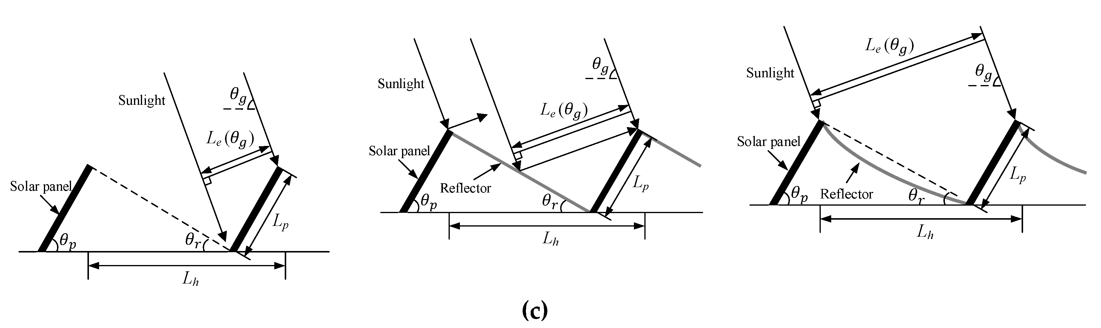
2.2. Effective Panel Length for the Elevation Angle of the Sun

The proposed reflector-based solar panel system is described in Figure 1, where θ p and θ r are the installation angle of the panel and reflector, L p and L r are likewise the lengths of the panel and the reflector, and h is both the height of the panel and the reflector, respectively. In order to obtain maximum power, it is important to choose the proper panel and reflector angle, as the altitude of the sun varies with the time and season. In the fixed-type solar power system, the angle of the panel is typically determined within the range of 0° to 60° [27,28]. However, there is a trade-off between the amounts of power generated in summer and winter according to the installation angle of the panel. If the installed panel angle is low, the amount of power generated can be maximized in summer in exchange for the greater power loss in winter due to the low incidence angle of the sunlight on the solar panel. On the other hand, the opposite is true if the installed angle of the panel is high. A reflector can be used to increase the power generated in summer without affecting the power generated in winter even if the installed panel angle is high. In this paper, the panel angle θ p is set to 60° for example, so that sunlight can enter the panel vertically in winter which can maximize the conversion efficiency when the latitude of the location is 36.5°, as it is at the experiment site in Korea. The reflector angle θ r is set to 30° so that the panel and the reflector are at a right angle which can minimize the inter-panel distance while avoiding shadows in winter. Moreover, in order to simplify the analysis, the efficiency change caused by the incident angle of sunlight into the solar panel or the optical loss of the reflector are ignored.
As shown in Figure 4, the amount of generated solar power is in proportion to the intensity of sunlight incident on the area of the solar panel, where L h is the horizontal length of the inter-panel considering the addition of the reflector which is represented as follows:
L h = L p ( cos θ p + sin θ p tan θ r )
Additionally, ground cover ratio (GCR) usually used for comparison with other configurations can be described as follows [29,30]:
GCR = L p L h = tan θ r cos θ p tan θ r + sin θ p
where the horizontal axis of the panel is assumed to be infinitely large.
The effective length L e ( θ g ) is increased by the amount of sunlight reflected by the reflector into the panel, which enhances the intensity of the sunlight entering the solar panel, as shown in Figure 4. The effective length can be categorized into three cases depending on θ g and θ r . Moreover, the effective length in each case varies depending on the type of reflector (the plane-type reflector or curved-type reflector) or whether a reflector is used. First, if θ g is lower than θ r ( θ g θ r ), the neighboring panel blocks the sunlight and all reflector types show an identical value of L e ( θ g ) . In this region, the unblocked panel length L s can be determined as follows [31,32]:
L s = L p · cos θ p + sin θ p / tan θ r cos θ p + sin θ p / tan θ g
Second, if θ g is between θ r and 2 θ r ( θ r < θ g 2 θ r ), all reflected sunlight by both the plane and curved reflectors enters the solar panel. In this region, both reflector types show an identical value of L e ( θ g ) which is higher than in the absence of a reflector, and L e ( θ g ) is determined by θ g and L h .
Third, if θ g is between 2 θ r and 2 θ r + θ p ( 2 θ r < θ g 2 θ r + θ p ), some of the sunlight reflected by the plane reflector does not enter the solar panel, whereas all of the sunlight reflected by the curved reflector enters the solar panel, as shown in Figure 4c.
Fourth, if θ g is higher than 2 θ r + θ p ( θ g > 2 θ r + θ p ), then L e ( θ g ) . of the plane reflector becomes the same with no reflector type as all of the sunlight reflected by the plane reflector does not enter the solar panel.
The effective length L e ( θ g ) with respect to θ g and the reflector type including GCR is summarized and plotted as shown in Table 1 and Figure 5, respectively. From Equations (5) and (6), and Table 1, following inequality for θ g can be satisfied:
L h sin θ g L p sin θ r sin θ r = L p L p cos ( θ g θ r ) ,   for   θ r < θ g 2 θ r
2 L h sin θ r cos ( θ g θ r ) = 2 L p sin ( θ p + θ r ) cos ( θ g θ r ) 2 L p sin ( θ p + θ r ) cos ( θ p + θ r ) = L p sin 2 ( θ p + θ r ) L p sin ( θ g + θ p ) ,   for   2 θ r < θ g 2 θ r + θ p
L h sin θ g L p ( cos θ p + sin θ p tan θ g ) sin θ g = L p sin ( θ g + θ p ) ,   for   θ g 2 θ r + θ p
Thus, L e ( θ g ) of the curved-type reflector is always higher than that of the plane-type regardless of θ g which also can be verified from Figure 5. The panel angle θ p is set to 60° for example in this paper, so that sunlight can be incident on the panel vertically in winter to maximize the conversion efficiency at the experiment site in Korea which has a latitude of 36.5°. To minimize the inter-panel distance and avoid the shadows in winter, the reflector angle θ r and the GCR are set to 30° and 0.5, respectively. As the output power is proportional to L e ( θ g ) from (1), the ratio of theoretical spatial average solar powers for no reflector, plane-type reflector, and curved-type reflector can be achieved from L e ( θ g ) , which is 1.00 : 1.53 : 1.80 when θ p = 60°, GCR = 0.5.

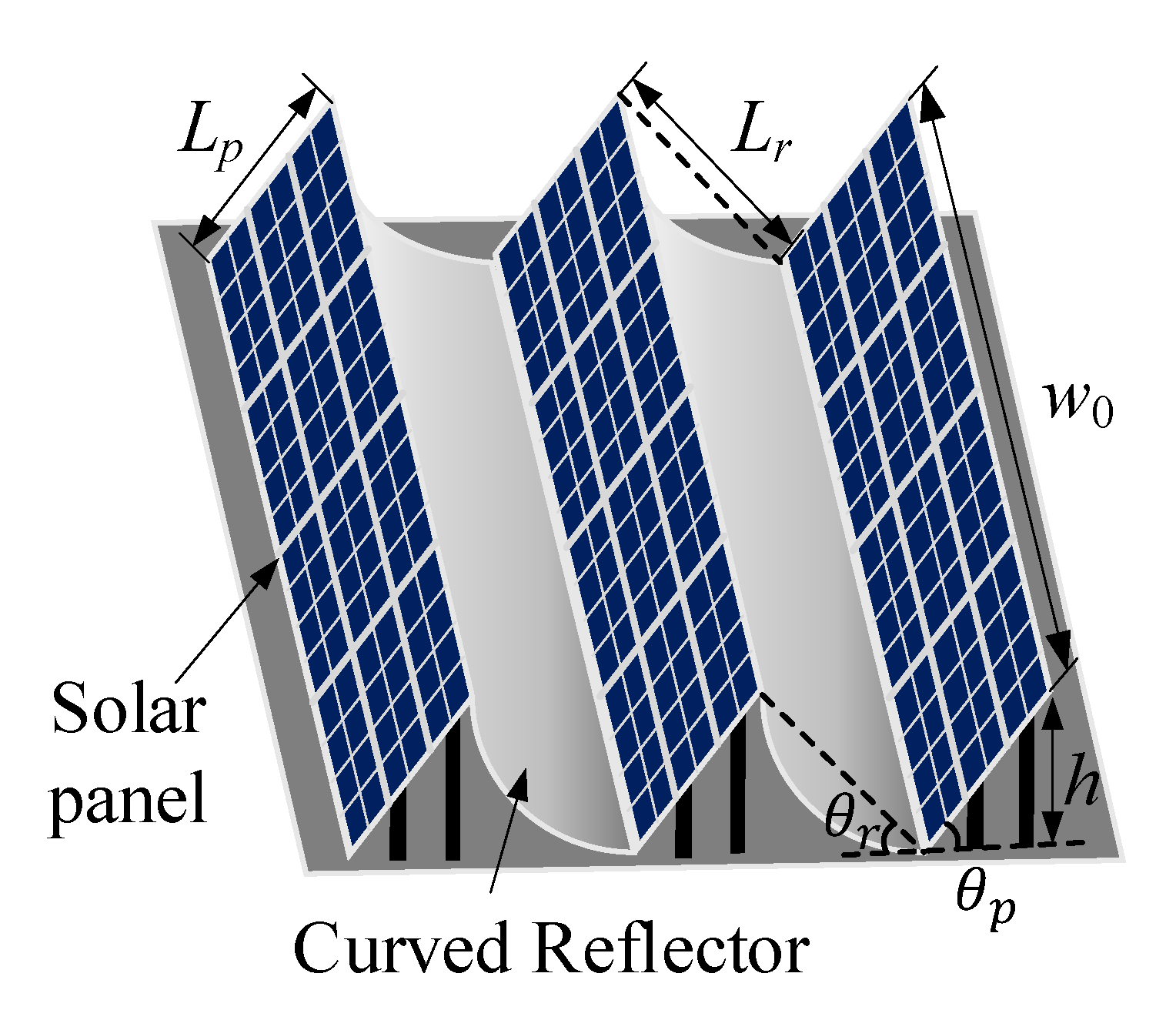
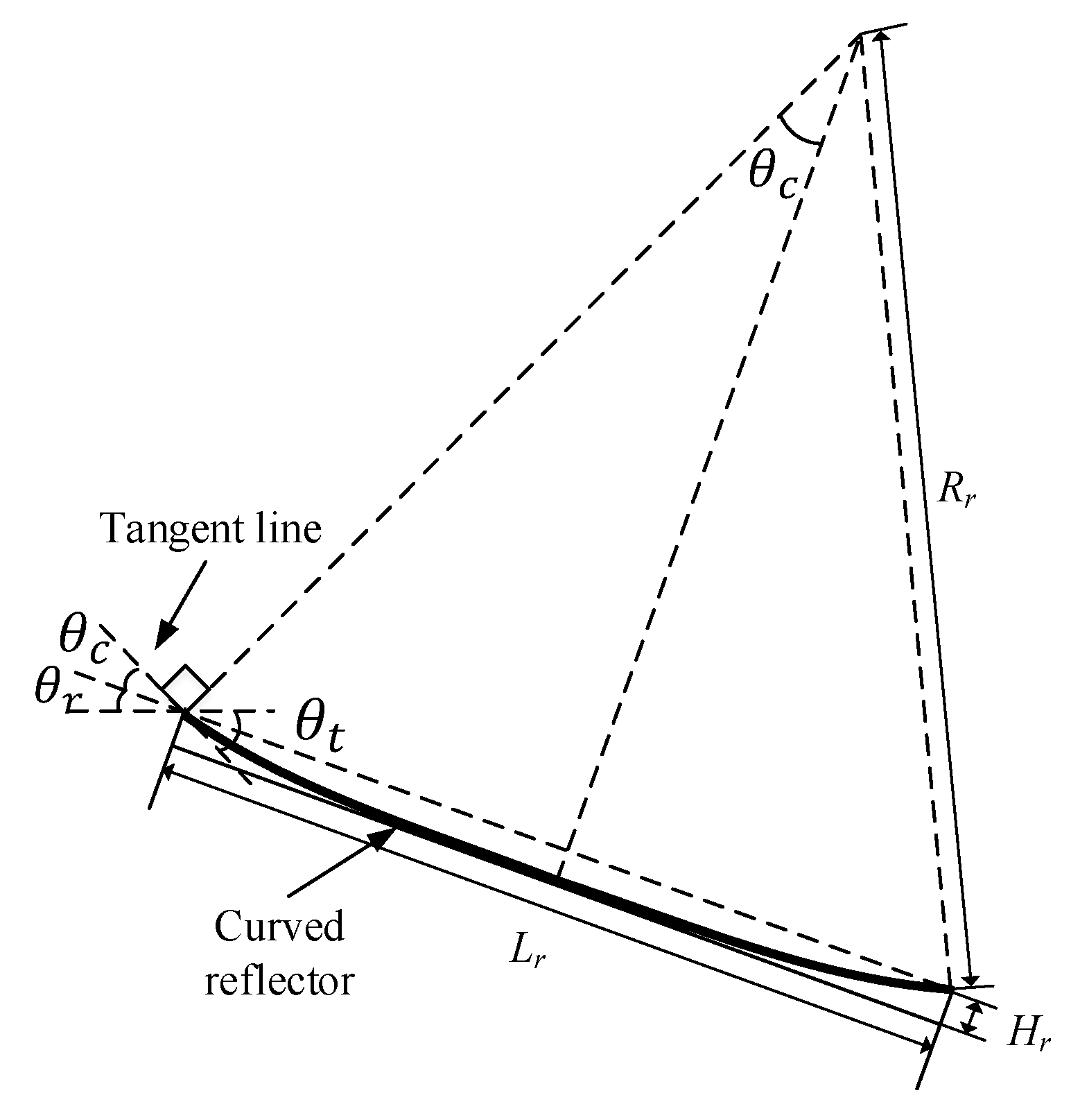
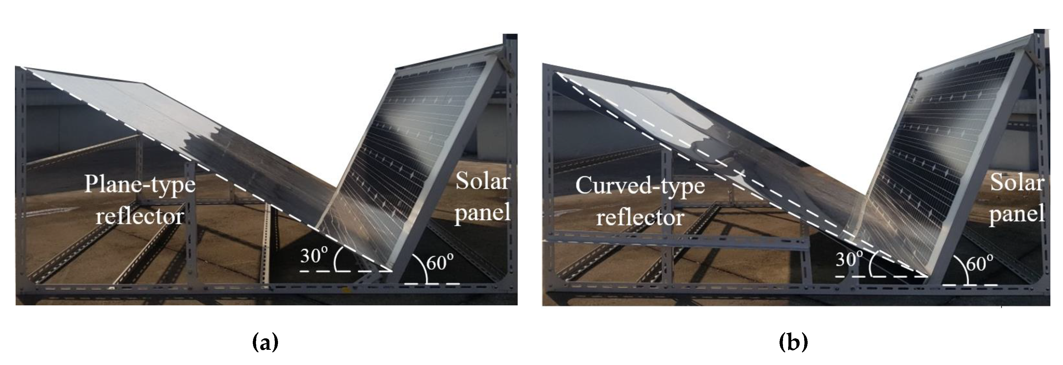
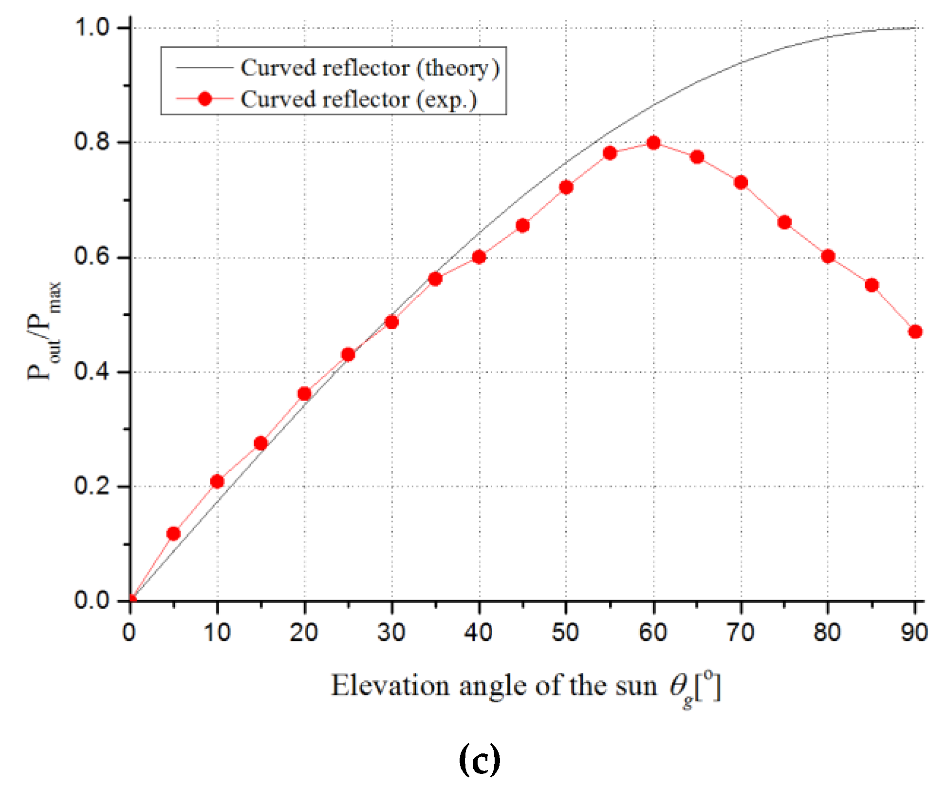
2.3. Design of the Curved Reflector

As shown in Figure 4c, some of the sunlight reflected by the plane-type reflector may not enter the solar panel when the elevation angle of the sun is high, which can decrease the efficiency. To avoid such sunlight leaks, the curved-type reflector must be designed carefully such that all of the reflected sunlight enters the panel regardless of the elevation angle of the sun. If all of the sunlight reflected by the curved-type reflector is incident on the panel when the sun’s altitude is at the meridian altitude in summer, θ g , m a x , leaked sunlight can be eliminated under all conditions, as shown in Figure 6. Sunlight with a maximum altitude in summer θ g , m a x can be represented as follows:
θ i + θ t θ g , m a x ,
where θ i is the angle between the sunlight and the tangent line at the endpoint of the curved reflector and θ t is the angle of the tangent line at the endpoint of the curved reflector.
In order to enter all of the reflected sunlight into the panel, θ i must be smaller than θ t , considering that a pair of angles opposite to each other are identical and the incident and the reflection angle are also identical at the reflector interface. This is expressed as follows:
θ i θ t
From Equations (11) and (12), the relationship between θ i and θ g , m a x can be expressed as follows:
θ i 1 2 θ g , m a x
When the sunlight enters at an angle lower than θ g , m a x , conditions of Equations (11)–(13) are met such that all of the reflected sunlight enters the panel regardless of the elevation of the sun. In this paper, θ t was set to 0.5 θ g , m a x , thus meeting the requirements.
Figure 7 shows parameters that determine the curvature of the proposed curved-type reflector. Note that H r and R r . are the height and radius of the curved reflector and θ C is the angle between the tangent line at the endpoint of the reflector and the line connecting the endpoints of the reflector. The parameters of θ t , θ r , and L r are given values determined by the installation environment and specifications of the solar panel. Thus, the curvature of the proposed curved reflector which meets the conditions of Equations (11)–(13) is determined by two parameters, H r and R r , which can be represented as follows:
H r = R r ( 1 cos θ c )
R r = L r 2 sin θ c
θ c = θ t θ r

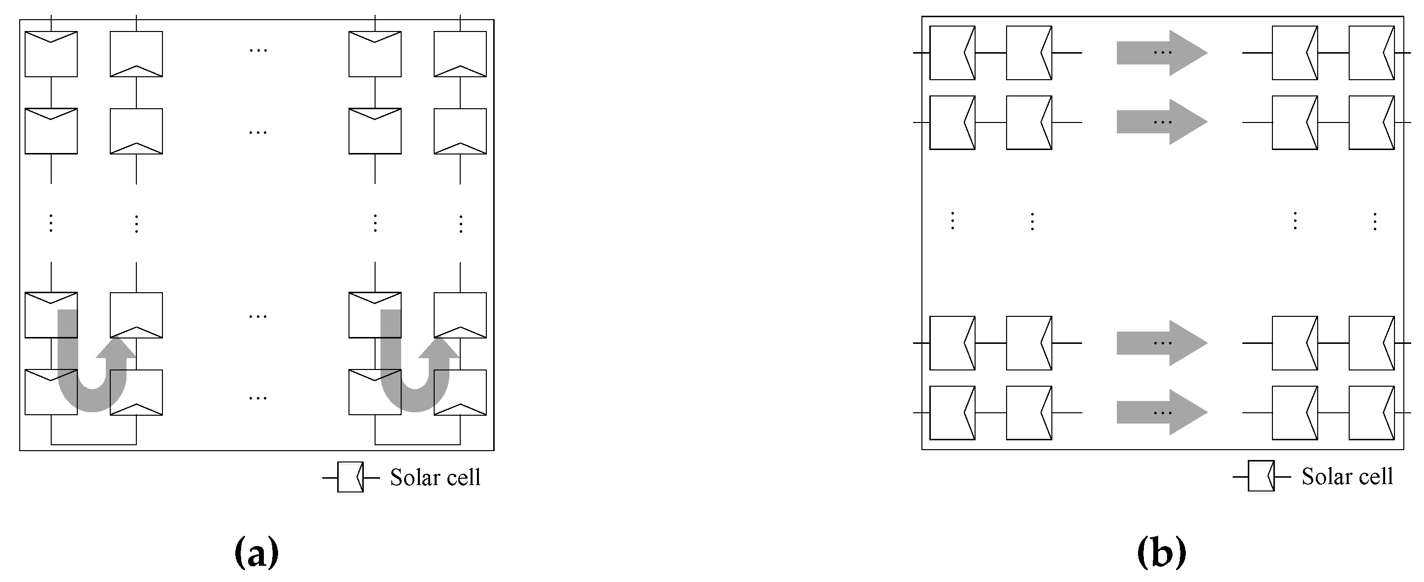
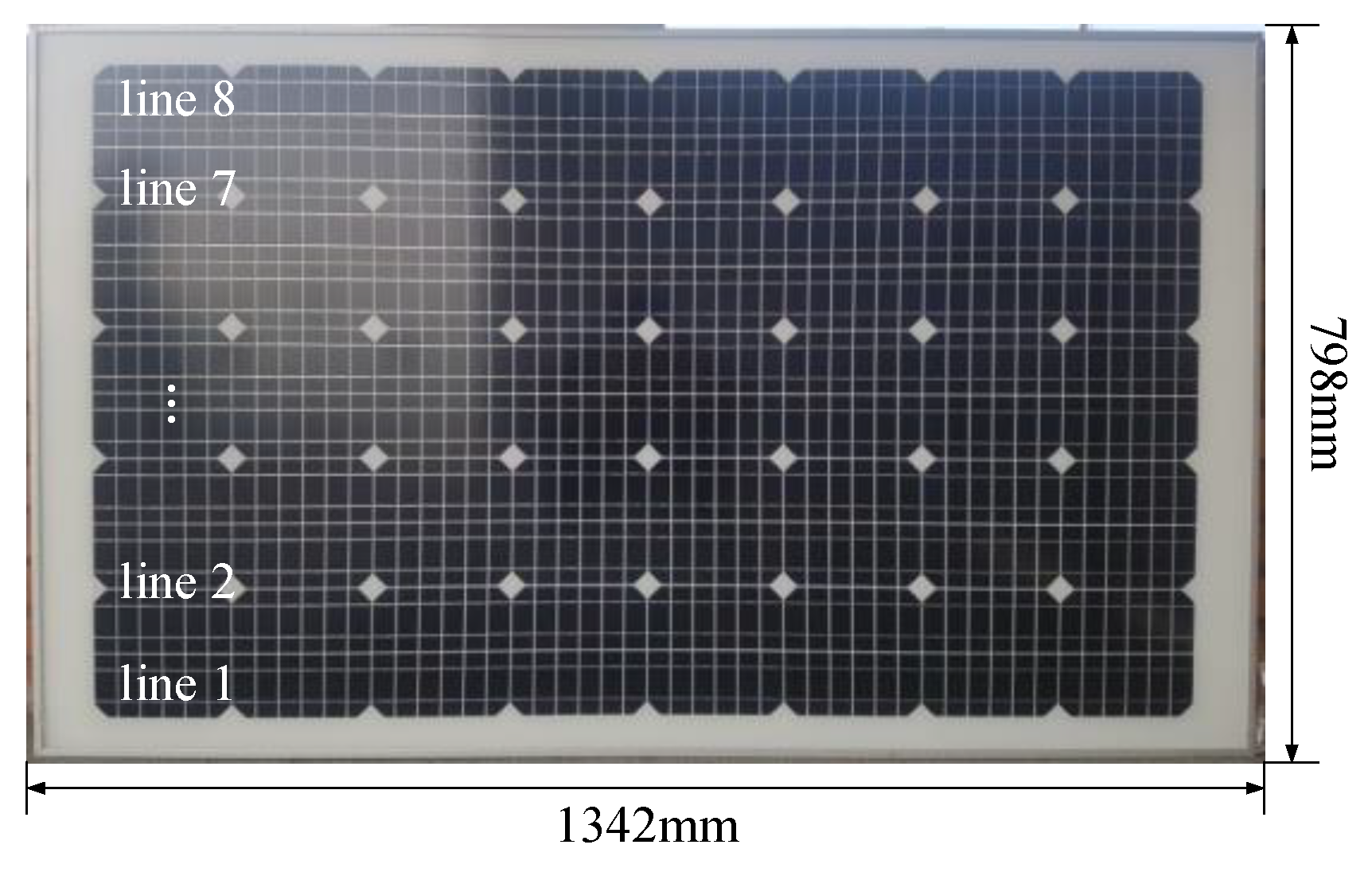
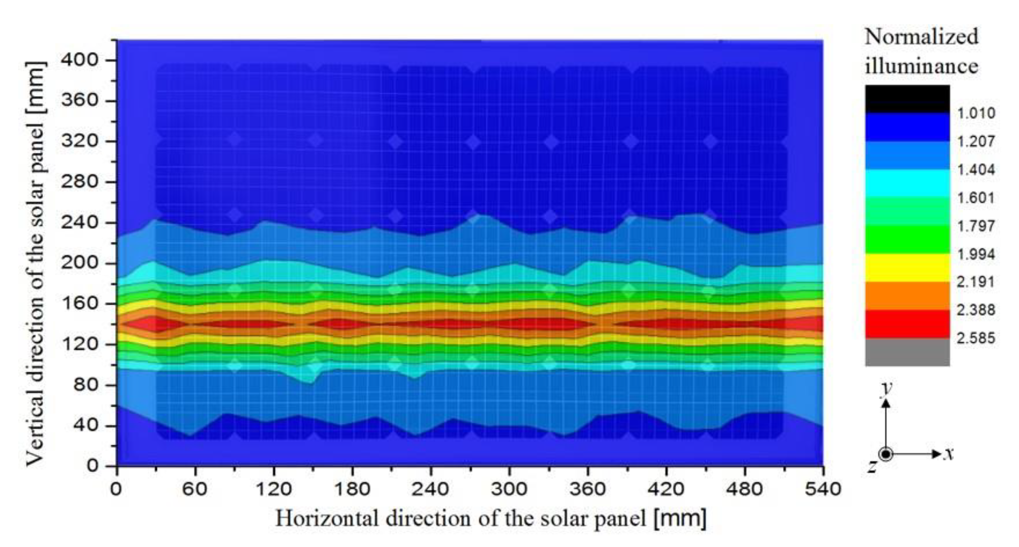
2.4. Design of the Solar Cell Configuration of the Solar Panel
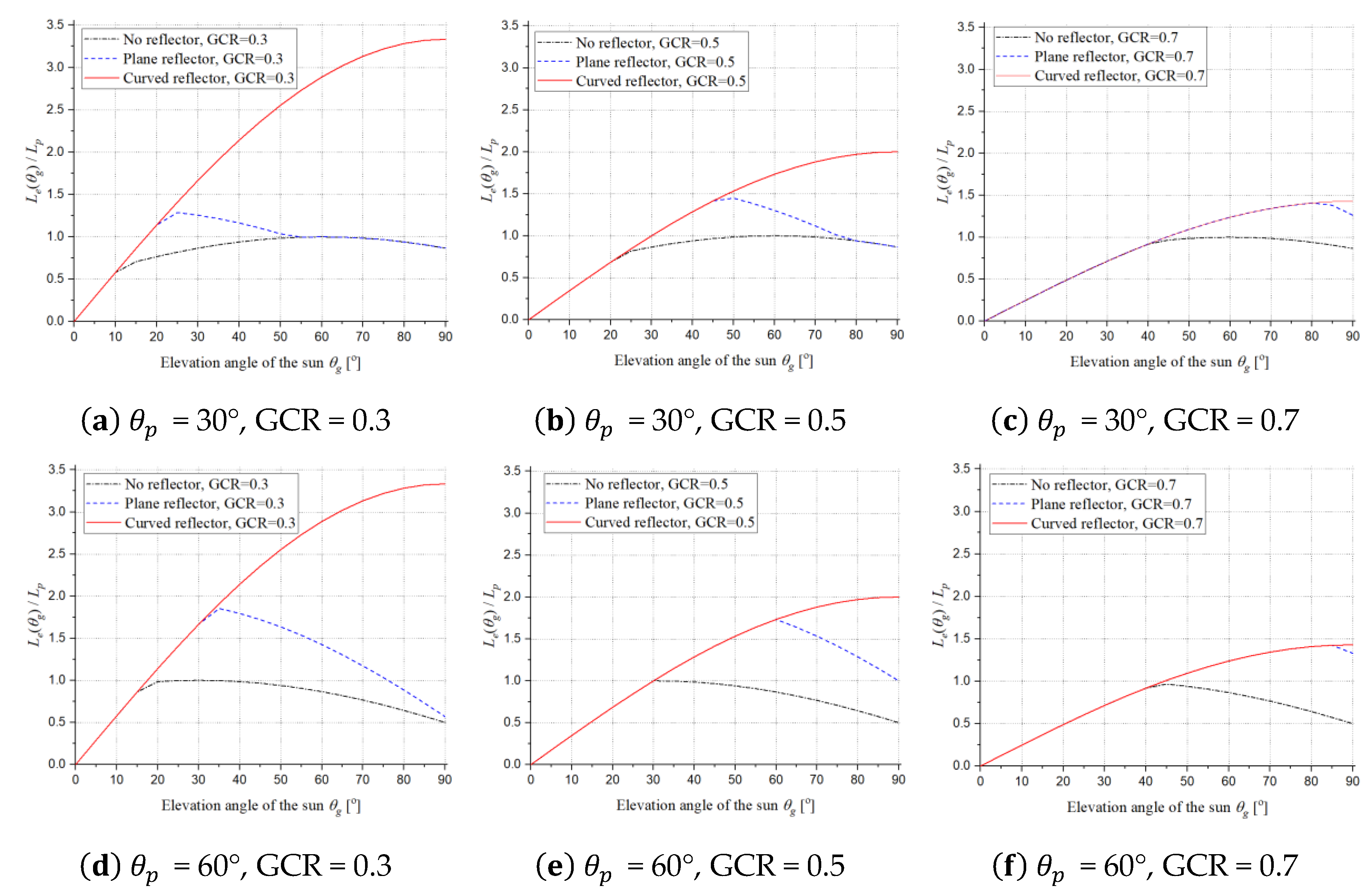
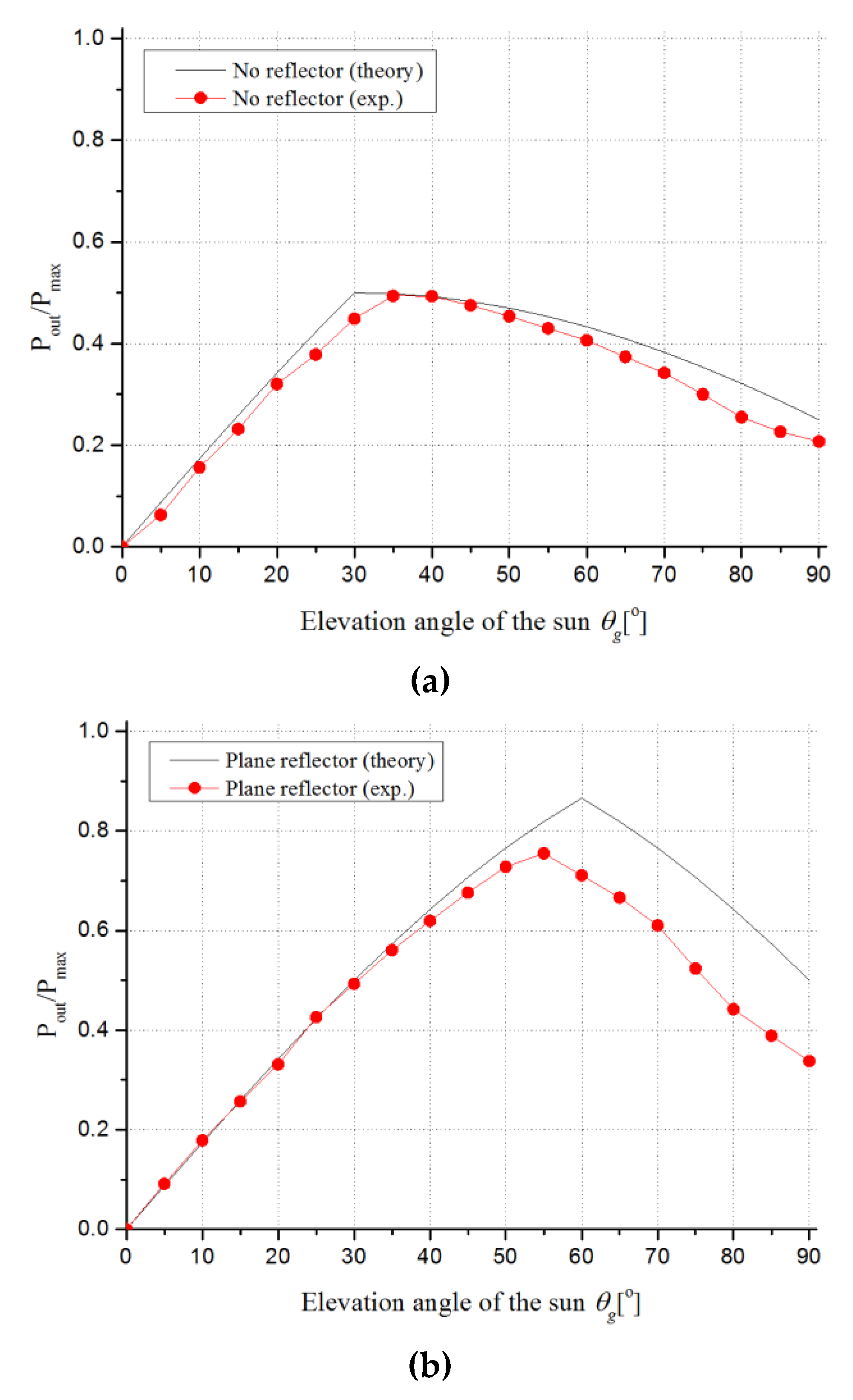
If the distribution of the light intensity incident on the solar panel is uneven, the power generated by the solar panel varies depending on the method used to connect the solar cells, such as a series connection or a parallel connection. For the curved-type reflector system, the intensity of the sunlight along the vertical line of the solar panel varies depending on the solar altitude and the curvature of the reflector. However, in conventional solar panels, solar cells are usually arranged vertically in series, as shown in Figure 8a. If the solar cell is connected in the conventional arrangement in the curved-type reflector system, the amount of generated power is determined by the solar cells at the weakest point of the sunlight. Therefore, the conventional configuration is not suitable for the proposed curved-type reflector solar power system, as the increased sunlight by the curved reflector cannot be used for power conversion.
Instead, a solar cell configuration that each horizontal line of the solar panel is connected in series is proposed in this paper, as shown in Figure 8b. As the sunlight intensity of each horizontal line of the panel is nearly constant regardless of the reflector type, the maximum power can be obtained in each line by arranging the solar cells as shown in Figure 8b.
The maximum power point (MPP) of the output power P o u t with respect to the reflector type is obtained in each case using the open-circuit voltage of each line V o c , k , the short-circuit current of each line I s c , k , and the fill factor of the solar panel F f which is the ratio of the maximum output power of the solar cell to the product of the open-circuit voltage and short-circuit current of the solar cell, where k represents the k th line of the panel, as described in Figure 9. This is expressed as follows [11]:
P o u t = F f k = 1 n V o c , k · I s c , k
where n is the number of series-connected solar cell lines of the panel.

3. Results

The proposed solar panel with the curved-type reflector was verified using an experimental prototype, as shown in Figure 10 and Figure 11. The solar panel was fabricated using eight lines of series-connected monocrystalline solar cells with 48 cells in each line, with the sectional area of 1342 mm by 798 mm, as shown in Figure 10. The three reflector designs (no reflector, the plane-type reflector, and the curved-type reflector) were fabricated and tested. Both the planar and curved reflectors were made of acrylic, with reflectivity of 85% for convenience of manufacturing, and the sectional area in both cases was 1342 mm by 1383 mm. The installation angles of the solar panel and the reflectors were set to 60° and 30°, respectively, and the latitude of the location where they were installed was 37.5°. The curvature of the curved reflector was set according to the parameters θ c and H r , which were set to 7.5° and 125 mm, respectively, such that all of the reflected sunlight can enter the solar panel where θ g , m a x is 75°.
To measure the maximum output power of the panel, as identified from Equation (17), the open-circuit voltage V o c , k and short-circuit current I s c , k of eight lines of the solar panel for each reflector type were measured simultaneously over various elevation angles of the sun θ g using LABVIEW, where n was set to 8. Additionally, the current-voltage characteristics of the fabricated solar panel were assessed, and the experimental value of fill factor F f was found to be 0.74.
Figure 12 shows the experimental results of P o u t for each reflector case with respect to θ g when it ranged from 0° to 90° in 5° steps. Since θ g , m a x is 75° in the installation environment for the latitude of 36.5° incident sunlight angle above θ g , m a x cannot be measured experimentally. Thus, experimental results where incident sunlight angles exceeding θ g , m a x were measured by leaning the entire solar power system. For example, θ g of 80° was measured by leaning the whole system 5 degrees to the direction of sunlight. Note that as the proposed curved type reflector was optimized at θ g , m a x , some of the reflected sunlight may not enter into the panel if the incident sunlight angle is above θ g , m a x . Each of the results was normalized according to P m a x , which is the maximum value of P o u t . As described in the analysis, the power generated by the solar panel was higher in the curved-type reflector as θ g increases due to the increased incident solar power entering the panel due to the curved-type reflector. When θ g exceeds 60°, the generated output power of the curved-type reflector decreases, as the angle of incidence is high enough to decrease the conversion efficiency of the solar cell [33] and the curved-type reflector was designed for θ g , m a x of 75°. The ratio of the measured spatial average solar powers for no reflector, plane-type reflector, and curved-type reflector was 1.00 : 1.45 : 1.61. This ratio is a little less than the theoretical result of 1.00 : 1.53 : 1.80, as the reflectivity of the reflector is not ideal and the efficiency of the solar cell depends on the angle of the incident light or its actual temperature. The experiment values for θ g > 60° deviate from the theory, as shown in Figure 12b,c due to the non-ideal reflectivity of reflectors.
However, the proposed curved reflector basically aims to increase the incident light on the panel dramatically compared to the conventional system, and the temperature increment effect can be minimized by changing the curvature of the curved reflector. As the goal of this paper is to verify the effectiveness of the curved-type reflector, long-term performance and a time average comparison among the reflector types during the year or day was not done, and this remains as future work.
The maximum output power from the solar panel for three cases which are no reflector, plane-type reflector, and curved-type reflector, is summarized in Table 2. Output power was measured when the sunlight illuminance is 100 kLux, which is the same as the illuminance of direct sunlight. The theoretical value was calculated based on the characteristics of the fabricated solar panel. The result shows that not only the spatial average power but also the maximum output power is higher than the other two cases when the curved reflector is adopted.
Figure 13 shows the measured uneven characteristics of the illuminance distribution of the curved-type reflector when the elevation angle of the sun is 60°. A total of 242 points were measured and each result was normalized by the minimum value of the illuminance. The results indicate that reflected sunlight was concentrated along the horizontal line as the light distribution of the reflected sunlight is not even. Therefore, the horizontal connection of the solar cells in series is more suitable for the proposed curved-type reflector-based solar power system. The concentration of the reflected sunlight can be mitigated by adjusting the curvature of the curved-type reflector, which remains as future work.

4. Conclusions

Solar panels using the curved-type reflector showed significantly increased generated solar power compared to conventional systems with no reflector or plane-type reflector. Complete theoretical analyses on the performance of the curved-type and plane-type reflectors according to the elevation angle of the sun are first shown in this paper. With the proposed curved-type reflector, all of the reflected sunlight enters the panel regardless of the elevation angle of the sun. The ratio of experimental results for the spatial average solar power for no reflector, plane-type reflector, and curved-type reflector was 1.00 : 1.45 : 1.61. The proposed theoretical models are found to be quite accurate except for a higher elevation angle of the sun, where reflectivity of the non-ideal reflectors is deteriorated. The proposed curved-type reflector can be easily installed between existing solar panels, which increases the solar power generation on average of up to 61%. It is demonstrated throughout this paper, that reflectors are one of the promising solutions for solar power generation. Especially a curved-type reflector is a better solution than the plane-type one. However, the efficiency improvement for a higher elevation angle of the sun was not effective due to the non-ideal reflectivity of the reflectors.
To improve the efficiency of the reflector-type solar power generation for a higher angle of the sun, as well as to determine the minimum reflectivity of reflectors for achieving a given efficiency improvement, are left for future works.

Author Contributions

Conceptualization, J.S.C., B.G.C. and S.-T.R.; Data curation, B.G.C.; Formal analysis, J.S.C.; Investigation, J.H.K.; Project administration, C.T.R. and Y.-S.K.; Writing—original draft, J.S.C.; Writing—review & editing, C.T.R. and Y.-S.K.

Funding

This research received no external funding.

Conflicts of Interest

The authors declare no conflict of interest

References

  1. Masters, G.M. Renewable and Efficient, Electric, Power, Systems; John, Wiley & Sons: Hoboken, NJ, USA, 2013. [Google Scholar]
  2. Kroposki, B.; Johnson, B.; Zhang, Y.; Gevorgian, V.; Denholm, P.; Hodge, B.; Hannegan, B. Achieving a 100% renewable, grid: Operating, electric, power, systems with, extremely, high, levels of, variable, renewable, energy. IEEE Power Energy Mag. 2017, 15, 61–73. [Google Scholar] [CrossRef]
  3. Sangwongwanich, A.; Blaabjerg, F. Mitigation of interharmonics in, PV systems with maximum power point tracking modification. IEEE Trans. Power Electron. 2019, 34, 8279–8282. [Google Scholar] [CrossRef] [Green Version]
  4. Sundareswaran, K.; Sankar, P.; Nayak, P.S.R.; Simon, S.P.; Palani, S. Enhanced energy output from a, PV system under partial shaded conditions through artificial bee colony. IEEE Trans. Sustain. Energy 2015, 6, 198–209. [Google Scholar] [CrossRef]
  5. El-Dein, M.Z.S.; Kazerani, M.; Salama, M.M.A. Optimal photovoltaic array reconfiguration to reduce partial shading losses. IEEE Trans. Sustain. Energy 2013, 4, 145–153. [Google Scholar] [CrossRef]
  6. Koran, A.; LaBella, T.; Lai, J. High efficiency photovoltaic source simulator with fast response time for solar power conditioning systems evaluation. IEEE Trans. Power Electron. 2014, 29, 1285–1297. [Google Scholar] [CrossRef]
  7. Jäger-Waldau, A. Snapshot of, Photovoltaics—February 2019. Energies 2019, 12, 769. [Google Scholar] [CrossRef] [Green Version]
  8. Hu, Y.; Cao, W.; Wu, J.; Ji, B.; Holliday, D. Thermography-based virtual, MPPT scheme for improving, PV energy efficiency under partial shading conditions. IEEE Trans. Power Electron. 2014, 29, 5667–5672. [Google Scholar] [CrossRef] [Green Version]
  9. Xenophontos, A.; Bazzi, A.M. Model-based, maximum, power, curves of, solar, photovoltaic, panels under, partial, shading, conditions. IEEE J. Photovolt. 2018, 8, 233–238. [Google Scholar] [CrossRef]
  10. Taretto, K.; Soldera, M.; Koffman-Frischknecht, A. Material, Parameters and, Perspectives for, Efficiency, Improvements in, Perovskite, Solar, Cells, Obtained by, Analytical, Modeling. IEEE J. Photovolt. 2017, 7, 206–213. [Google Scholar] [CrossRef]
  11. Subudhi, B.; Pradhan, R. A comparative study on maximum power point tracking techniques for photovoltaic power systems. IEEE Trans. Sustain. Energy 2013, 4, 89–98. [Google Scholar] [CrossRef]
  12. Seyedmahmoudian, M.; Rahmani, R.; Mekhilef, S.; Oo, A.M.T.; Stojcevski, A.; Soon, T.K.; Ghandhari, A.S. Simulation and hardware implementation of new maximum power point tracking technique for partially shaded, PV system using hybrid, DEPSO method. IEEE Trans. Sustain. Energy 2015, 6, 850–862. [Google Scholar] [CrossRef]
  13. Wu, S.; Xiong, C. Passive cooling technology for photovoltaic panels for domestic houses. Int. J. Low Carbon Technol. 2014, 9, 118–126. [Google Scholar] [CrossRef] [Green Version]
  14. Ghosh, S.; Rahman, S.; Pipattanasomporn, M. Distribution voltage regulation through active power curtailment with, PV inverters and solar generation forecasts. IEEE Trans. Sustain. Energy 2017, 8, 13–22. [Google Scholar] [CrossRef]
  15. Strache, S.; Wunderlich, R.; Heinen, S. A comprehensive, quantitative comparison of inverter architectures for various, PV systems, PV cells, and irradiance profiles. IEEE Trans. Sustain. Energy 2014, 5, 813–822. [Google Scholar] [CrossRef]
  16. Weckx, S.; Gonzalez, C.; Driesen, J. Combined central and local active and reactive power control of, PV inverters. IEEE Trans. Sustain. Energy 2014, 5, 776–784. [Google Scholar] [CrossRef]
  17. Pelaez, S.A.; Deline, C.; Greenberg, P.; Stein, J.S.; Kostuk, R.K. Model and validation of single-axis tracking with bifacial, PV. IEEE J. Photovolt. 2019, 9, 715–721. [Google Scholar] [CrossRef]
  18. Molin, E.; Stridh, B.; Molin, A.; Wackelgard, E. Experimental yield study of bifacial, PV modules in, Nordic conditions. IEEE J. Photovolt. 2018, 8, 1457–1463. [Google Scholar] [CrossRef]
  19. Pavlov, M.; Migan-Dubois, A.; Bourdin, V.; Pons, M.; Haeffelin, M. Experimental and numerical study of the influence of string mismatch on the yield of, PV modules augmented by static planar reflectors. IEEE J. Photovolt. 2015, 5, 1686–1691. [Google Scholar] [CrossRef] [Green Version]
  20. Augustin, D.; Chacko, R.; Jacob, J. Canal top solar, PV with reflectors. In Proceedings of the 2016 IEEE International, Conference on Power, Electronics, Drives and, Energy, Systems (PEDES), Trivandrum, India, 14–17 December 2016. [Google Scholar]
  21. TenKsolar, Hopes to, Raise, Funds for, Wave-Like, Solar, System. Available online: https://gigaom.com/2011/04/26/tenksolar-raising-funds-for-wave-like-solar-system/ (accessed on 2 October 2019).
  22. Energy, Farm, Co. LTD. Photovoltaic Power Generation Device. JP Patent 2012. Available online: http://abpat.kipris.or.kr/abpat/biblioa.do?method=biblioFrame&searchFg=N&publ_key=JP201400103381A0&cntry=JP&start=biblio (accessed on 2 December 2019).
  23. Matsushima, T.; Setaka, T.; Muroyama, S. Concentrating solar module with horizontal reflectors. Solar Energy Mater. Solar Cells 2003, 75, 603–612. [Google Scholar] [CrossRef]
  24. Alam, S.M.S.; Rahman, A.N.M.M. Performance comparison of mirror reflected solar panel with tracking and cooling. In Proceedings of the 2016 4th IEEE International Conference on the Development in the in Renewable Energy Technology (ICDRET), Dhaka, Bangledash, 7–9 January 2016. [Google Scholar]
  25. Joardder, M.U.H.; Halder, P.K.; Rahim, M.A.; Masud, M.H. Solar pyrolysis: converting waste into asset using solar energy. In Clean Energy for Sustainable Development: Comparisons and Contrasts of New Approaches; Academic Press: Cambridge, MA, USA, 2017. [Google Scholar]
  26. Choi, J.S.; Kim, J.H.; Rim, C.T. Incidence solar power analysis of, PV panels with curved reflectors. In Proceedings of the 2017 18th IEEE Workshop on Control and Modeling for Power Electronics (COMPEL), Stanford, CA, USA, 9–12 July 2017. [Google Scholar]
  27. Karafil, A.; Ozbay, H.; Kesler, M.; Parmaksiz, H. Calculation of optimum fixed tilt angle of, PV panels depending on solar angles and comparison of the results with experimental study conducted in summer in, Bilecik, Turkey. In Proceedings of the 2015 9th IEEE International Conference on Electrical and Electronics Engineering (ELECO), Bursa, Turkey, 26–28 November 2015. [Google Scholar]
  28. Bakirci, K. General models for optimum tilt angles of solar panels: Turkey case study. Renew. Sustain. Energy Rev. 2012, 16, 6149–6159. [Google Scholar] [CrossRef]
  29. Doubleday, K.; Choi, B.; Maksimovic, D.; Deline, C.; Olalla, C. Recovery of inter-row shading losses using differential power-processing submodule, DC–DC converters. Solar Energy 2016, 135, 512–517. [Google Scholar] [CrossRef] [Green Version]
  30. Narvarte, L.; Lorenzo, E. Tracking and ground cover ratio. Prog. Photovolt. Res. Appl. 2008, 16, 703–714. [Google Scholar] [CrossRef]
  31. Passias, D.; Källbäck, B. Shading effects in rows of solar cell panels. Solar Cells 1984, 11, 281–291. [Google Scholar] [CrossRef]
  32. Bany, J.; Appelbaum, J. The effect of shading on the design of a field of solar collectors. Solar Cells 1987, 20, 201–228. [Google Scholar] [CrossRef]
  33. Rahman, M.S.S.; Alam, M.K. Effect of angle of incidence on the performance of bulk heterojunction organic solar cells: A unified optoelectronic analytical framework. AIP Adv. 2017, 7, 065101. [Google Scholar] [CrossRef]
Figure 1. Proposed curved-type reflector for solar power generation.
Energies 12 04602 g001
Figure 2. Perspectives of solar panel arrangements according to the inter-panel distance and elevation angle of the sun: (a) no reflector without shadows in winter, (b) no reflector without shadows in summer, (c) plane-type reflector with a loss of sunlight in summer, and (d) curved-type reflector without a loss of sunlight in summer.
Energies 12 04602 g002
Figure 3. Description of the solar panel and incident sunlight in vector form at an arbitrary date and time.
Energies 12 04602 g003
Figure 4. Configuration of the effective panel length according to the elevation angle of the sun and the reflector type: (a) low angle ( θ g θ r ), (b) middle angle ( θ r < θ g 2 θ r ), and (c) high angle ( θ g > 2 θ r ): no reflector (left), plane-type reflector (middle), and curved-type reflector (right).
Energies 12 04602 g004aEnergies 12 04602 g004b
Figure 5. Theoretical results of L ( θ g ) / L p with respect to θ g , which is plotted for θ p = 30°, 60°, and GCR = 0.3, 0.5, 0.7, for example.
Energies 12 04602 g005
Figure 6. Description of the solar panel system with a curved reflector and sunlight with an elevation angle of θ g .
Energies 12 04602 g006
Figure 7. Description of the curved reflector with parameters that determine the curvature of the reflector.
Energies 12 04602 g007
Figure 8. Description of (a) the conventional and (b) the proposed solar cell configurations best fit for the curved-type reflector.
Energies 12 04602 g008
Figure 9. Description of the maximum output point of the kth line of the proposed solar cell configuration.
Energies 12 04602 g009
Figure 10. Fabricated solar panel with series-connected solar cells in each line.
Energies 12 04602 g010
Figure 11. Fabricated prototypes of (a) the planar-type reflector and (b) the proposed curved-type reflector solar power system.
Energies 12 04602 g011
Figure 12. Experimental results of P o u t / P m a x with respect to the elevation angle of the sun θ g and the reflector type: (a) no reflector, (b) plane-type reflector, and (c) curved-type reflector.
Energies 12 04602 g012aEnergies 12 04602 g012b
Figure 13. Measured illuminance distribution of the solar panel with a curved-type reflector when the elevation angle of the sun is 60°.
Energies 12 04602 g013
Table 1. Effective length L e ( θ g ) according to the elevation angle of the sun θ g and the type of reflector.
L e ( θ g ) No ReflectorPlane-Type ReflectorCurved-Type Reflector
Low angle ( θ g θ r ) L s sin ( θ g + θ p ) L s sin ( θ g + θ p ) L s sin ( θ g + θ p )
Middle angle ( θ r < θ g 2 θ r ) L p sin ( θ g + θ p ) L h sin θ g L h sin θ g
High angle ( 2 θ r < θ g < 2 θ r + θ p ) L p sin ( θ g + θ p ) 2 L h sin θ r cos ( θ g θ r ) L h sin θ g
High angle ( 2 θ r + θ p < θ g ) L p sin ( θ g + θ p ) L p sin ( θ g + θ p ) L h sin θ g
Ground cover ratio (GCR) tan θ r cos θ p tan θ r + sin θ p tan θ r cos θ p tan θ r + sin θ p tan θ r cos θ p tan θ r + sin θ p
Table 2. Comparison of maximum output power for no reflector, plane-type reflector, and curved-type reflector.
No ReflectorPlane-Type ReflectorCurved-Type Reflector
Theory (W/100kLux)107.0 ( θ g = 30°)185.3 ( θ g = 60°)214.0 ( θ g = 90°)
Experiment (W/100kLux)105.6 ( θ g = 35°)161.5 ( θ g = 55°)171.2 ( θ g = 60°)

