1. Introduction
The ocean covers about 70% of the earth’s surface and is considered to be one of the greatest renewable energy sources. Furthermore, the ocean waves are the largest untapped renewable energy source on the earth. The ocean waves have a tremendous amount of energy and potential to contribute to a significant amount of renewable energy around the world. The energy carried by the oceans, particularly waves, have several significant advantages such as high source availability, high load factor, less environmental impact and source predictability compared to other renewable energy sources [
1,
2]. Apart from that, the power density of wave energy is greater than that of the solar energy and wind [
3]. On average, the ocean waves can generate over 100 kW/m energy density, which is far higher than solar and wind intensity. Meanwhile, the global ocean wave power potential is approximated to be up to 10 TW, and the annual ocean wave energy is approximated to be up to 93,000 TWh [
1]. Because of these reasons, ocean waves have been promising renewable energy resources to reduce the dependency on fossil fuels for the purposes of generating electricity.
Recently, the high potential of ocean waves power has attracted a lot of attention around the world. The International Energy Agency (IEA) had launched a technology collaboration program on ocean energy system (OES) to conduct research and development of advanced conversion technologies to generate usable electricity from the ocean renewable resources, i.e., waves, currents, tides and et cetera [
4]. Moreover, the United States (U.S) Department of Energy (DoE) has introduced the Water Power Program with the aim of developing innovative technologies for electrical power generation from water resources across the United States [
5]. In addition, the DoE of U.S also has announced USD 10 million funding to establish a new physical testing program for marine technologies, including a wave conversion system device. Besides that, the European Marine Energy Centre (EMEC) and Qingdao Pilot National Laboratory for Marine Science and Technology (QNLM) have collaborated to develop the first marine energy converters test centre in China for conducting research and development of ocean wave and tidal conversion technologies [
6].
Over the past decades, various technologies of a wave energy conversion system exist that are designed to extract energy from the ocean resources and convert it into usable electricity. Majority of the technologies are still at a premature stage, and only a few developed devices have been tested in the open sea condition. In [
7,
8,
9,
10], many reviews on wave energy conversion technologies have been presented. According to [
11,
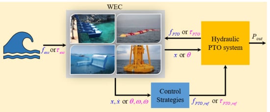
12], the wave energy conversion system is comprised of three main parts, namely the wave energy converter (WEC) device, the power take-off (PTO) system and the control and instrumentation subsystem. A WEC device is the primary component of a wave energy conversion system that absorbs and exploits the ocean wave power. The WEC device is connected to the PTO subsystems against which it will actively transfer forces and motions. Meanwhile, a PTO system converts the captured oscillating power from the WEC device into usable electricity. In addition, the control (instrumentation) subsystem is used to take care of the control of the dynamic behaviour of WEC and the PTO system to the incident wave conditions.
There is a wide variety of wave energy conversion system that have been designed, developed and experimentally tested, resulting from the different ways of ocean wave energy absorption and also depending on the location characteristics. Recent reviews identified about over than a thousand techniques of wave energy conversion technologies that have been patented around the world, especially in Europe, North America and Japan [
8]. Since there are considerable variations in designs of wave energy conversion system, several methods have been proposed to classify the systems in terms of, installed location, working principle, PTO system and et cetera [
10,
12,
13,
14]. The popular ways of classification are based on the working principle of the WEC device and the PTO system. According to the International Energy Agency (IEA), the wave energy conversion technologies can be categorised into three main groups based on the working principles, i.e., oscillating water column (OWC), wave-activated-bodies (WAB) and overtopping type [
12]. Although, in several articles, the WAB also is known as oscillating bodies (OS). A detail description of OWC, WAB and overtopping devices can be obtained in [
15,
16,
17,
18], respectively.
PTO system is a mechanism to convert the energy absorbed from the ocean waves by WEC into usable electricity [
12]. Therefore, a PTO system is the heart of the wave energy conversion system. The PTO system is the essential element, as it directly correlates to the amount of the absorbed wave power converted into usable electricity. Meanwhile, the mass and size of the PTO system also directly contribute to the dynamic design of the wave energy conversion system. There are variety of PTO mechanisms that have been proposed by researchers and developers in the wave energy conversion system, i.e., based on turbine (air and hydro), direct-mechanical drive system, direct-electrical drive and hydraulic [
12].
Turbine coupled with the generator is one type of PTO system utilised in the wave energy conversion system. Turbine PTO is widely used in the wave energy conversion system, and its concept is similar to the PTO system used in the wind and hydropower generation. In a wave energy conversion system, the turbines PTO system is driven by the compressed air or water. The air-turbine PTO is frequently used in the OWC wave energy conversion system. The kinetic energy in the air is converted to electricity using a coupled air-turbine and generator. The turbine is driven by the bi-directional flow of compressed air in the OWC chamber. However, this bi-directional nature of the airflow is a significant challenge of the air-turbine PTO system. Therefore, several types of self-rectifying air-turbines have been invented and used in many OWC applications such as Wells turbine, Dennis-Auld turbine and impulse turbines and et cetera [
19]. The Wells turbine is the simplest type of self-rectifying turbines. The Well turbine is probably the best option for wave energy conversion application because of high efficiency and low cost [
20]. Examples of wave energy conversion system that utilised the air-turbine PTO system are Pico [
21], Limpet [
22], Leacon [
23], Oceanlinx [
24] and et cetera. Hydro-turbine PTO system is another type of turbine PTO used in the wave energy conversion system. The hydro turbine is the most mature PTO system, as it has been utilised for several decades in the hydropower generation system. Hydro turbines can operate at efficiency values of an excess of 90% and require low maintenance. Hydro-turbine PTO is mostly used in the overtopping wave energy conversion system. Kinetic energy from the ocean waves drives a low head hydro-turbine generator to produce electricity. Several types of hydro-turbine have been invented, such as the Kaplan turbine, Francis turbine, Pelton turbine and et cetera. Several wave energy conversion systems such as Tapchan [
10], Crown [
25], Aquabuoy [
7], Wave Dragon [
26], Overtopping Breakwater for Energy Conversion (OBREC) and Seawave Slot-Cone Generator (SSG) [
27] and et cetera have used this PTO system.
Another type of PTO system is direct-mechanical drive PTO. Direct-mechanical drive PTO is defined as system conversion of mechanical energy from the WEC subjected to the ocean wave motion into electricity using a mechanical interface to force rotary electrical generator. The direct-mechanical drive PTO system is potentially high efficiency, small size and reliability since it does not have the intermediate stages of energy conversion, i.e., hydraulic, pneumatic, or pumped water, which may result in a lower cost of energy [
28,
29]. The mechanical interface in the direct-mechanical PTO system is different for various applications of wave energy conversion. Typically, the mechanical interface consists of a gearbox, pulleys, cables, sprocket, rand geared shaft/rack. The direct-mechanical PTO system is fit for the essential translation and rotation type of WEC. There have been many concepts of a mechanical interface were proposed for the direct-mechanical PTO system in wave energy conversion system [
30,
31,
32,
33,
34,
35]. A rack-and-pinion and the slider-crank mechanism are most frequently used in the direct-mechanical PTO system [
35]. One of the challenges of the direct-mechanical drive PTO system implementation is the requirement for frequent maintenance since many moving parts are used in the system. Most moving parts relatively have short lifetime.
Apart from that, the direct-electrical drive PTO system is referred to the system which directly converts the mechanical energy absorbed by the WEC device to the electrical energy using the electrical machine or linear generator [
12]. The direct-electrical drive PTO system is much simple compared to the other types of PTO system, as it has no mechanical interface between the WEC and the PTO system. Since the mechanical interfaces are unnecessary, the friction energy loss from this moveable part is greatly reduced, thus can increase the power conversion efficiency [
36] and reduce the maintenance cost for this system [
37]. In general, this type of PTO system is well-suited for small-scale (<10 kW) WEC devices [
38]. There are several types of conventional linear generator that can be utilised in the direct-electrical drive PTO system, i.e., induction machine, switched reluctance machine, synchronous machine and permanent magnet synchronous generator (PMSG) [
12]. However, the permanent magnet synchronous generator has been the most selected option for wave energy conversion applications. The relative motion between the translator and stator drive within the WEC parts generates electricity [
39]. Currently, this PTO concept has been implemented in several wave energy conversion systems such as Wavebob [
40], L10 buoy [
41], SINN Power [
42], Uppsala Seabased [
43], Archimedes Wave Swing [
44] and et cetera. There are several challenges that have to be encountered during the implementation of this PTO system. First, the technology of the linear generator for wave energy conversion system is still in a premature stage because of the lack of manufacturer and distributor of this machine. The physical size and weight of a linear generator is another challenge of this PTO system in the wave conversion system application. Theoretically, the linear generator size and the mass is dependent on the rated force of the WEC device. Since the peak velocity is as low as 2 m/s, the low speed and high torque of a linear generator has to be used, resulting in a huge and heavy machine.
The hydraulic PTO system is the most appropriate PTO mechanism for converting wave energy into usable electricity, especially for the WAB wave energy conversion system. Hydraulic PTO system has significant advantages because of its excellent characteristics, i.e., well-suited to low-frequency and large power density waves [
45]. The hydraulic PTO system uses incompressible fluid, which results in higher efficiency. It was reported in the literature that the efficiency of a hydraulic PTO system in a typical wave energy conversion system could be achieved up to 90% [
46]. Moreover, the hydraulic PTO system also can be effectively used to control the WEC device according to the ocean wave condition in order to maximise energy absorption [
47]. Consequently, the hydraulic PTO system also can be assembled using standard hydraulic components that are readily available from hydraulic component suppliers [
11]. Generally, the hydraulic PTO system is comprised of the hydraulic cylinder, the check valve, the hydraulic motor, the hydraulic accumulators, and hoses to connect the different components. The reciprocating motion of the WEC will compress and decompress the fluid in the hydraulic actuator chamber and forcing fluid to flow through hydraulic check valves to a hydraulic motor, which in turn drives the electric generator [
48]. Examples of wave energy conversion system which utilised the hydraulic PTO system in their system are Pelamis [
49], Wave star [
50], Eco wave power [
51], Waveroller [
52] and et cetera. Several issues have arisen when using a hydraulic PTO system in a wave energy conversion system, such as provide a negative impact on the marine environment in case a leakage occurs. However, there are some alternative biodegradable fluid instead of traditional mineral oil, which can be utilised to solve such an obstacle.
In recent years, several works on wave energy conversion system have been reviewed, i.e., the review of wave energy conversion modelling methods [
53,
54,
55,
56], review of wave energy conversion technologies [
7,
8,
9,
10] and review of control strategies for wave energy conversion system [
13,
14,
36]. However, majority of these review articles focused on the broad field of wave energy conversion system. There is no specific review article that is specifically focused on the hydraulic PTO concepts. In addition, to the best of our knowledge, the review of control mechanisms in a hydraulic PTO system is also less presented in the literature. Therefore, in this paper,
Section 2 presents the review of various concepts of hydraulic PTO for the wave energy conversion system,
Section 3 provides the advance control mechanisms of hydraulic PTO system, and finally,
Section 4 describes the benefits and challenges of hydraulic PTO system.
2. Multi-Concepts of Hydraulic Power Take-Off System
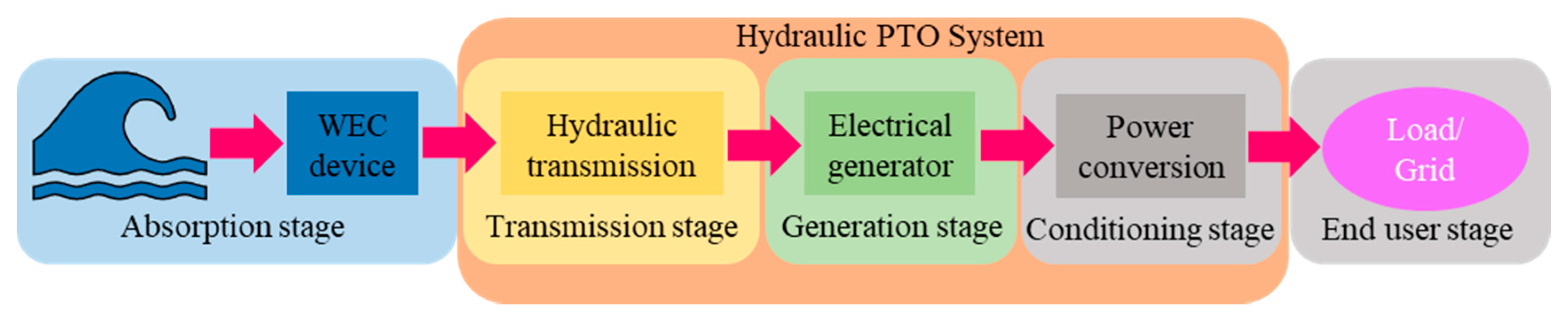
The structure of the WEC with a hydraulic PTO system is illustrated in
Figure 1. It comprises four different stages, i.e., absorption, transmission, generation and conditioning stage [
55]. The absorption stage involves the conversion of energy from the ocean wave motion to mechanical energy using a specific mechanical design of WEC. The hydraulic PTO system is responsible for converting the absorbed mechanical energy to electrical energy through multiple processes during transmission, generation and conditioning stages, as shown in
Figure 1. The mechanical energy in the form of force is absorbed by the hydraulic actuator because of the reciprocating motion of WEC and translated into fluid energy during the transmission stage and transformed into electrical energy in the generation stage. Finally, the generated electricity from the generator is adapted by the power electronic controllers subjected to the specific requirement in the conditioning stage before being delivered to the grid and load.
The hydraulic PTO system consists of different main modules which have its functions, i.e., actuation, rectification, reservoir and generation. Actuation module is used to absorb the mechanical energy from the interaction of WEC with the ocean waves into fluid energy. The actuation module commonly comprises of single or multiple hydraulic cylinder actuators with different kinds of configurations. Single-acting or double-acting hydraulic cylinder with a single or double rod type is widely used in the hydraulic PTO system. Meanwhile, a hydraulic rectification module is utilised to rectify the bi-directional fluid flow direction into the single-directional fluid flow. The hydraulic module includes check valves (two-valve, three-valve or four-valve system) or a digital directional control valve or hydraulic transformer.
Apart from that, a reservoir module is used to provide and accumulate fluid energy at several points during the smoothing process of the hydraulic pressure in the hydraulic PTO system. The reservoir module can be made of hydraulic tank or accumulator and pressure relief valve control. Sometimes, the electrical pump is also included in the reservoir module to accelerate the process of providing and accumulating fluid energy. Besides that, the generation module converts the fluid energy from the rectification module to become usable electricity. The generation module is comprised of a hydraulic motor coupled with an electrical generator. The hydraulic motor in the generation module can consist of either unidirectional or bi-directional of fixed or variable displacement type. By combining these modules, a different hydraulic PTO concept can be developed for the wave energy converter device.
Recently, a variety of hydraulic PTO concepts have been suggested in the literature for numerous types of wave energy conversion system, as reviewed in [
57,
58]. Identifying specific characteristics of different hydraulic PTO concepts is necessary to understand the advantages, limitations and complexity associated with the implementation. Generally, categorising hydraulic PTO system is difficult since there are a variety of ways to develop and implement a hydraulic PTO system. According to the [
46,
59], the hydraulic PTO system falls into two main groups, i.e., constant-pressure and variable-pressure system. This classification is referred to final pressure state of the hydraulic PTO system, which means the pressure in the generation module. Several examples of variable-pressure and constant-pressure of hydraulic PTO system applied in a wave energy conversion system are presented in the following subsection.
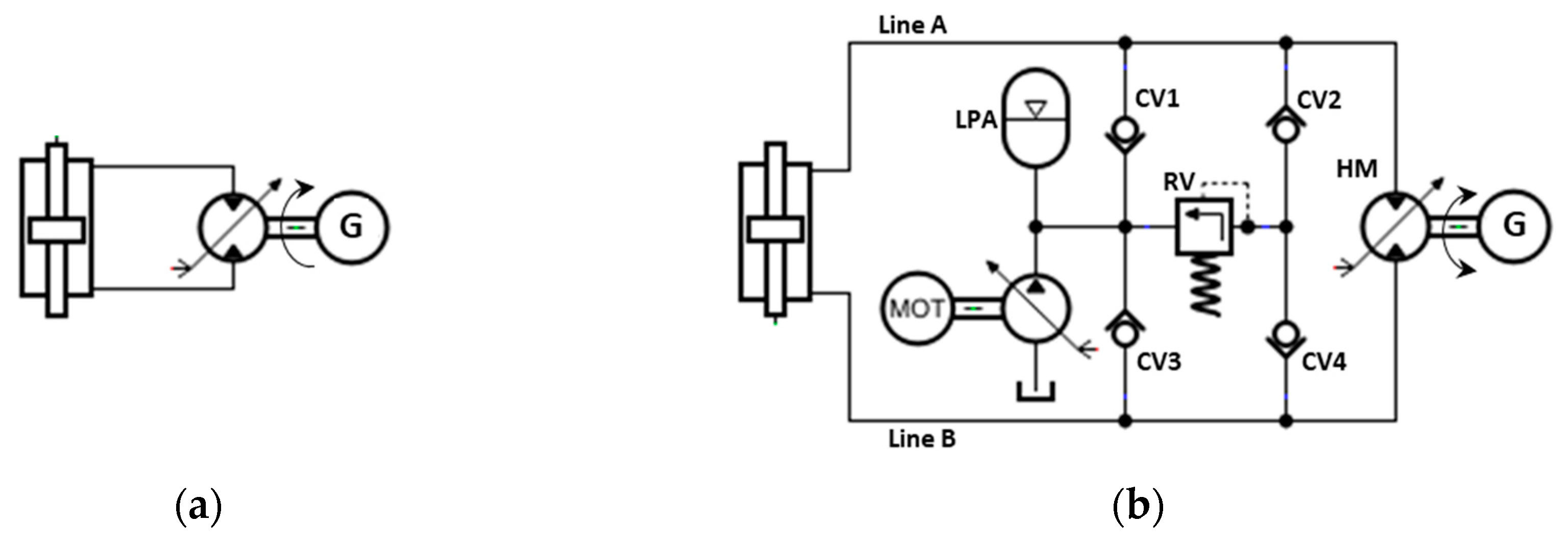
2.1. Variable-Pressure Concept
The concepts of hydraulic PTO system in the variable-pressure category is simple compare to the concepts of hydraulic PTO system in the constant-pressure category. Commonly, the hydraulic PTO concepts in the variable-pressure category are the combination of the actuation, reservoir and generation modules without considering the rectification module as presented in
Figure 2.
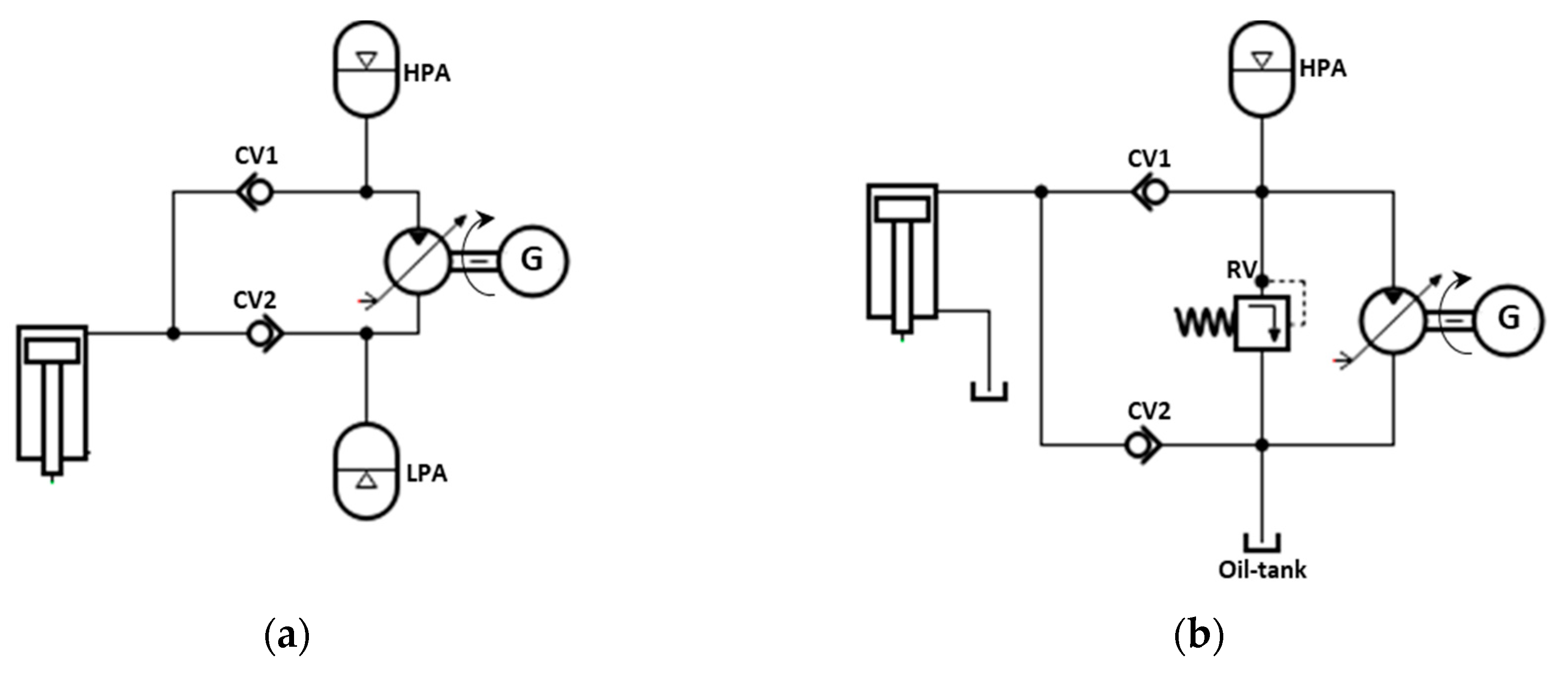
Figure 2a shows the conventional variable-pressure concept used in [
60]. The PTO concept is the simplest and most economical, as it consists of double-acting with double rods hydraulic cylinder (actuation module) directly connected to a bi-directional variable-displacement hydraulic motor (generation) which is coupled to a rotating electrical generator [
60]. The fixed or variable type of rotating electrical generator may be utilised in this concept. A hydraulic cylinder operates as a linear pump because of the reciprocating motion of WEC, generating a bi-directional hydraulic flow for turning the hydraulic motor and electrical generator. A hydraulic motor is required to provide two-quadrant operation, which means the hydraulic motor is able to accept or deliver fluid power from the bi-direction flow and to rotate in a single direction. In this concept, the several control strategies can be adopted, since the two-quadrant hydraulic motor is utilised. This conventional concept has been studied in [
60], where three different control strategies have been investigated. The simulation result indicated that the conversion efficiency of this concept using the proposed control strategy could be achieved at 65% during the bigger waves and reduced to 45% during smaller waves. However, the authors revealed that this concept has the drawback of unable to store the energy because of the unavailability of hydraulic accumulator. This drawback also causes the smoothing of inconsistent fluid pressure cannot be carried out in this concept.
Because of these shortcomings, the modified concept of a variable-pressure hydraulic PTO system based on the conventional concept in
Figure 2a has been proposed as presented in
Figure 2b [
59,
61]. In this concept, the reservoir module, which includes directional check valves, relief valve, and LP accumulator, is included to overcome the drawbacks of the conventional variable-pressure concept. The relief valve protects the PTO system from over-pressure, and the LP accumulator prevents the cavitation incident in the LP side of the PTO system [
61]. The check valves in the reservoir module control the fluid flow direction in the line A and B. During high-pressure state, the line A and B are connected to the relief valve, while during the low-pressure state, the line A and B are connected to LP accumulator. In addition, a booster pump is included in a reservoir module, as presented in
Figure 2b, to fill up the reduced amount of fluid because of the nature of leakage in the hydraulic motor. In [
61], the study has been carried out to obtain the efficiency of this modified concept, and the simulation results show the efficiency of this modified concept improved over than 65%.
2.2. Constant-Pressure Concept
The concepts based on the constant-pressure hydraulic PTO system are alternative to the variable-pressure hydraulic PTO system. In the wave energy conversion application, the concepts based on the constant-pressure received more attention rather than the one based on the variable-pressure hydraulic PTO system. Generally, the various hydraulic PTO concepts in the constant-pressure category consist of hydraulic actuation, rectification, reservoir and generation modules combination. Since there are various concepts based on the constant-pressure system, the actuation module consists of various types of hydraulic cylinder actuators either single-acting with single rod or double-acting with single rod or double rods of a hydraulic cylinder or multi-chamber with a single rod and et cetera. While, the rectification module is composed of check valves (2-valves or 4-valves system), or directional control valve or hydraulic transformer. The reservoir module used in these concepts consists of hydraulic high-pressure (HPA) and low-pressure (LPA) accumulator, oil-tank, pressure relief valve and booster pump. Meanwhile, the generation module includes the unidirectional hydraulic motor (fixed or variable displacement) coupled to the electrical generator.
The constant-pressure concept has significant advantages in terms of efficiency and flexibility of control. Generally, the effectiveness of constant-pressure concept is much higher rather than a variable-pressure concept, especially for the advanced version of the constant-pressure concept, where the efficiency can be reached up to 90% [
46]. The excellent achievement is due to the flexibility of this concept in implementing advanced control strategies. However, its flexibility feature has caused some drawbacks in terms of complexity and economic aspects. The flexibility control has made this concept more complicated rather than variable-pressure concept [
62]. Besides that, the constant-pressure concept is more costly, since there are several active hydraulic components, such as active control valve, digital displacement actuator and et cetera, which is necessary to be utilised especially in the advanced version of the constant-pressure concept.
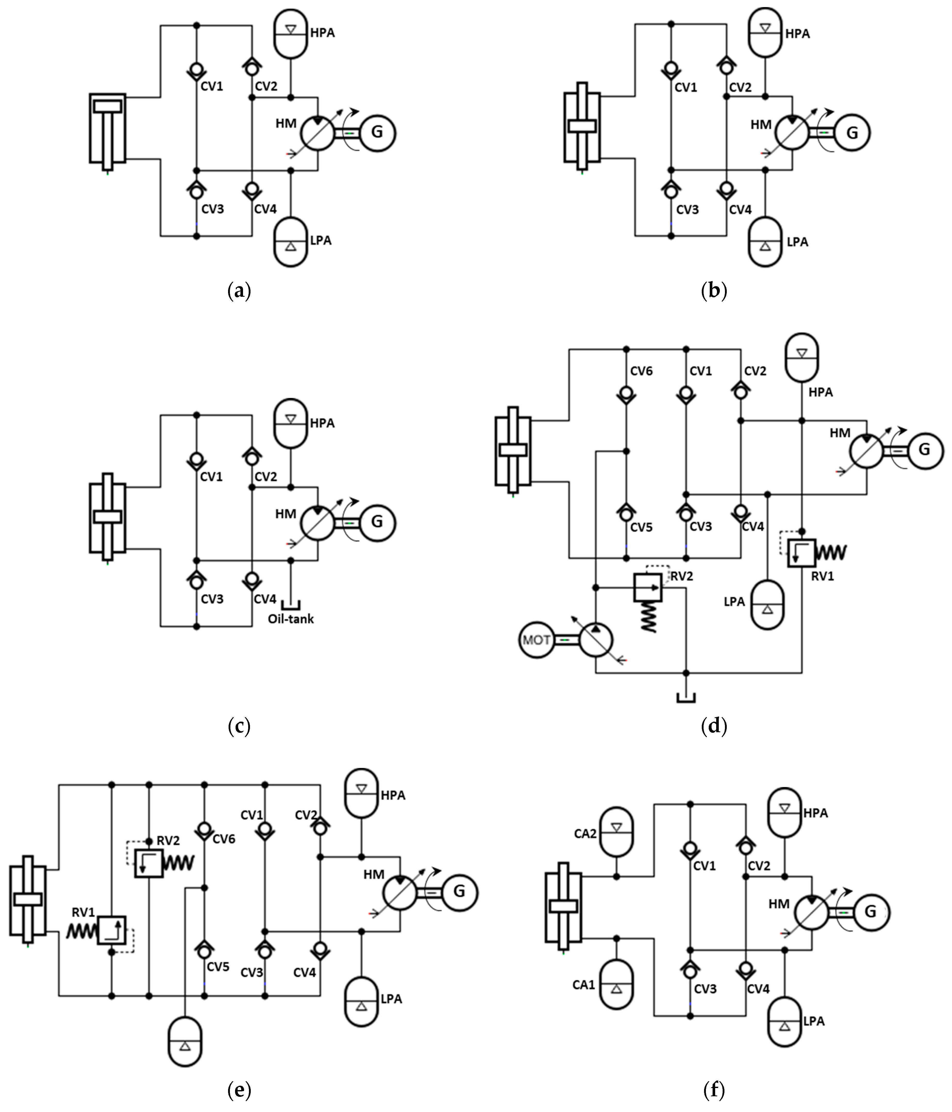
2.2.1. Constant-Pressure Hydraulic PTO Based on Two-Check Valves Concepts
Figure 3a illustrates the simplest concept in the constant-pressure category labelled as CP-Type I. This concept has a single-acting with single rod hydraulic in the actuation module connected to a rectification module which includes a simple 2-valves system approach to rectify the fluid flow from the actuation module to a hydraulic motor. HP and LP accumulators are placed at the inlet and outlet of the generation module to constrain the pressure of the hydraulic motor at the desired ranges. The reciprocating motion of the WEC device caused by the ocean waves force drives the piston up and forced the fluid in the large chamber of the actuator to flow through CV1 and HPA to the hydraulic motor. When the piston moves down, the fluid is forced to flow from the hydraulic motor through the LPA and CV2 to the small chamber of actuator. In this hydraulic PTO concept, the fluid always flowing in a single-direction and directly drives the hydraulic motor, and electrical generator rotates in one direction. The simulation studies of this PTO concept has been carried out in [
63], where a bond graph method has been proposed to model this PTO system. The numerical simulation results demonstrated that this PTO concept is inefficient because of the resonance characteristics of ocean wave motion. The use of a single-acting hydraulic cylinder and can waste the part of the extracted power.
The concept of CP-Type II in
Figure 3b is almost similar to the concept of CP-Type I, where the two check valves system is utilised. This concept has been applied in [
64]. It has a double-acting with single rod hydraulic actuator, two-check valves system, HP accumulator with pressure relief valve, a single-direction hydraulic motor coupled electrical generator and a small oil tank as presented in
Figure 3. In this concept, the large actuator chamber is connected to the rectification module, while the small actuator chamber is connected to the oil-tank. For safety reason, the high-pressure line is connected to the pressure relief valve (RV) to prevent the system from the over-pressurised fluid flows because of extremely high-power waves. In this concept, only the upward motion of the double-acting hydraulic actuator is utilised for energy harvesting. During the upward movement, the piston forces the high-pressure fluid in the large cylinder chamber to flow to the inlet of the hydraulic motor via CV1 and directly turns the electrical generator drives. Then, the fluid flows from the outlet of the hydraulic motor back to the oil-tank and small cylinder chamber. On the other hand, during the downward motion of the piston, the low-pressure fluid flows from the oil tank back to the large cylinder chamber through CV2. At this motion, the pressure of the hydraulic motor is not affected. In [
65], a similar concept of hydraulic PTO has been applied in their study. However, in this concept, the reservoir module consists of a couple of accumulators (HP and LP) that were used instead of the HP accumulator and oil-tank.
2.2.2. Constant-Pressure Hydraulic PTO Based on Four-Check Valves Concepts
In order to solve the drawbacks in concepts of CP-Type I and II in
Figure 3, the concepts of the hydraulic PTO system presented in
Figure 4 can be considered. The rectification module in the concept of CP-Type I and II can be replaced with a four-valve rectifier, as presented in
Figure 4. The concept of CP-Type III in
Figure 4a shows the basic concept of hydraulic PTO with a four-check valves system [
47]. In this concept, a double-acting with a single rod hydraulic actuator is utilised, where the large cylinder chamber is connected to the CV1 (inlet) and CV2 (outlet). Meanwhile, the small cylinder chamber is connected to the CV3 (inlet) and CV4 (outlet). The rest connection of the components in this concept is almost similar to the concepts of CP-Type I and II, as presented in
Figure 4a. The four-check valves rectification system used in this hydraulic PTO concept is similar to a Graetz circuit implemented with diodes used in the power electronics conversion system, where the check valve is used instead of a diode. In the four-check valves rectification system, only two check valves operating during each half cycle motion (upward or downward) of the double-acting hydraulic actuator are used. When the piston motion goes upward, the high-pressure fluid from the large hydraulic chamber flows to the HP accumulator, hydraulic motor, LP accumulator and back to the small hydraulic chamber through CV2 and CV3. In contrast, during the downward motion, high-pressure fluid from the small hydraulic chamber flows to the HP accumulator, hydraulic motor, LP accumulator and back to the large hydraulic chamber through CV4 and CV1. Similar to the concepts of CP-Type I and II, the fluid flowing in the hydraulic motor in unidirectional mode directly rotates the electrical generator in unidirectional direction. The concept presented in
Figure 4a has been applied in many applications of wave energy conversion systems [
47,
66,
67,
68,
69].
Since a double-acting with single rod hydraulic actuator is utilised in this concept as presented in
Figure 4a, the operation of this hydraulic PTO concept is unbalanced, which means the fluid pressures and the fluid flows in each actuator cylinder chamber are unbalanced because of asymmetry in their effective working areas on the two sides of the piston. The flow and the pressure in the chamber consist of the rod are less compared to the other side chamber. Consequently, the extent and re-tract movement of the hydraulic actuator piston is unbalanced if the same force is applied. A rodless side chamber requires more force compared to the other side to move the piston at the same velocity for both chambers. Thus, the unsymmetrical characteristic in this PTO concept affects the hydrostatic behaviour of the WEC device. Moreover, complicated control is required for this concept because of the different constraints of both chambers. In addition, the sizing of the other components such as check valves and et cetera, may not be identical in both circuit sizes.
The unbalanced problem of the concept of CP-Type III in
Figure 4a can be solved by replacing the single-rod double-acting hydraulic actuator with the double-rod double-acting hydraulic actuator, as presented in
Figure 4b (CP-Type IV concept). A balanced-type cylinder actuator can be used to reduce the complicated design, sizing and control of the PTO system. However, a balanced-type hydraulic actuator has less force rather than an unbalanced-type hydraulic actuator at the same fluid pressure. Also, it requires more space to work because of the double-length compared to the concept of CP-Type III. This concept has been applied in several studies of wave energy conversion systems, for example, in [
61,
70]. Furthermore, a different configuration of the reservoir module also can be used in the concepts of CP-Type III and IV, as illustrated in
Figure 4c. In the CP-Type V concept, the oil-tank is used instead of the LP accumulator because of the larger capacity. This concept has been applied in some wave energy conversion studies, such as in [
71,
72,
73,
74,
75,
76,
77]. However, the use of oil-tank alone without any external pressure source, such as a hydraulic pump can make it less efficient. In a real application, there will be external leakage from the hydraulic motor to the oil-tank [
78].
Consequently, the concept of CP-Type VI, as presented in
Figure 4d can be considered to improve the weakness of the CP-Type III and V concepts. In this concept, the reservoir module consists of a booster pump, pressure relief valves (RV1 and RV2) and check valves (CV5 and CV6), which are connected to the oil-tank. RV1 only opens once the fluid pressure in the high-pressure line exceeds the allowed maximum pressure of the hydraulic motor. Meanwhile, a boost pump and RV2 are added to the oil-tank to prevent cavitation and maintain a minimum pressure in the system by regulating the system pressure using pressure relief valve. The check valves CV5 and CV6 are used to ensure the fluid never flows to the booster pump and oil-tank during normal pressure limits. This hydraulic PTO concept has been applied in several studies described in [
59,
78,
79,
80,
81,
82].
Meanwhile, another approach to keep a minimum pressure in the system is by adding an extra accumulator, as presented in
Figure 4e [
83]. Since the accumulator is used in the CP-Type VII concept, there no external electrical supply is required as needed in the CP-Type VI concept. In addition, pressure relief valves (RV1 and RV2) are used in this concept to limit the peak system pressure at a certain level and protect hydraulic components. Furthermore, the concept in
Figure 4b was modified by the addition of extra accumulators attached to the cylinder actuator via gate valves, as presented in
Figure 4f [
84]. This modification (CP-Type VIII) is intended to ensure the WEC device moves in phase with the motion of the waves by accumulating and discharging enough fluid power.
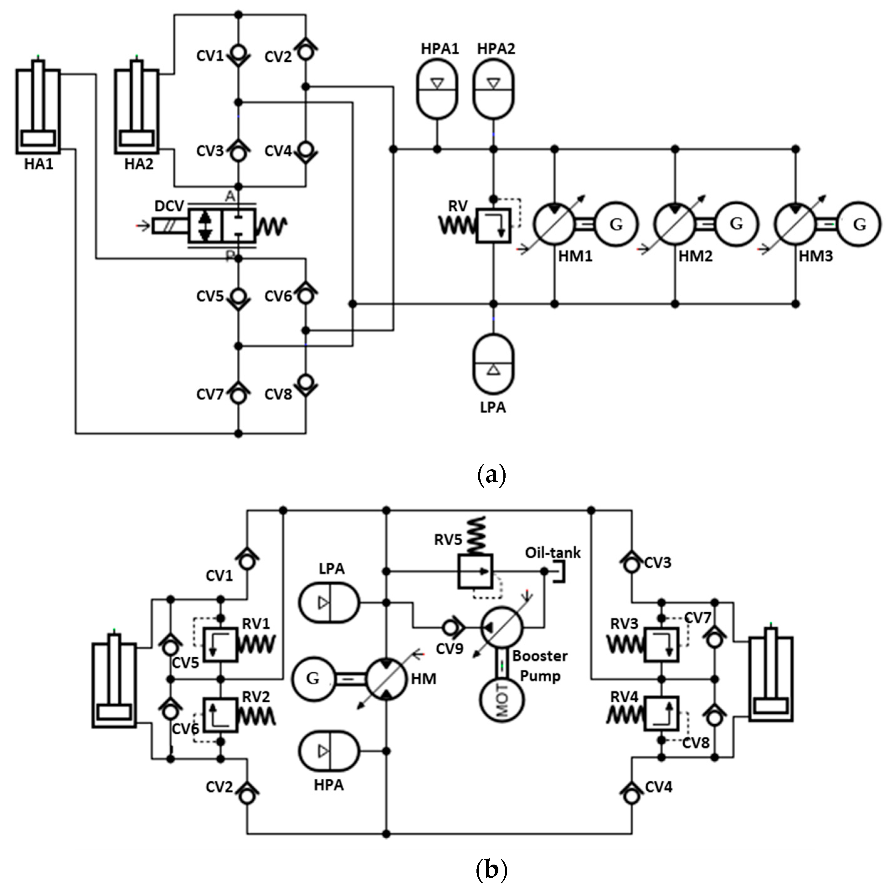
Instead of a single-action hydraulic PTO system, as presented in
Figure 4a–f, a double-action hydraulic PTO system also has been proposed for the wave energy conversion system.
Figure 5 shows a double-action hydraulic PTO system for pendulum-type WEC devices [
85]. In
Figure 5a, the CP-Type IX has a parallel coupling of a single rod double-acting cylinder actuator attached on one side of the pendulum type WEC device. Each double-acting cylinder actuator is connected to the four-valve rectification system parallel-coupled using an active by-pass valve, which is uniquely designed to switch-off/on the actuator cylinder chamber according to the ocean waves condition [
58]. The rectification module then is connected to the generation module, which has three sets of coupled hydraulic motor and electrical generators with different capacities, assembled in parallels, as presented in
Figure 5a. The operation of three sets of hydraulic motor and generator are controlled according to the fluid pressure flows to ensure the higher efficiency operation of the generation module.
Moreover, the concept of a double-action hydraulic PTO system with two hydraulic actuators also has been proposed, as presented in
Figure 5b [
86,
87]. In this concept, two single rod double-acting cylinder actuators are attached at each side of the flap of pendulum-type WEC device in the opposite direction. Each hydraulic cylinder is connected to a different four-valve rectification system, which controls the cylinder chambers according to the swing motion direction. During the operation, the hydraulic actuator moves in opposite directions and supplying the high-pressure fluid flows to the hydraulic motor during half-a-period of wave motion. Through this mechanism, the hydraulic motor can turn in drive the generator to generate electricity during the whole period. A boost pump is also added in the PTO system to provide the extra fluid flow to the hydraulic motor through check valves during a small hydraulic chamber (rod chamber) operation of a hydraulic actuator. This concept also has been used in attenuator type WEC devices such as Pelamis; however, a different configuration of the actuation module was used because of the different operation of this WEC device as described in [
88,
89,
90].
2.2.3. Constant-Pressure Hydraulic PTO Based on Directional Control Valves Concepts
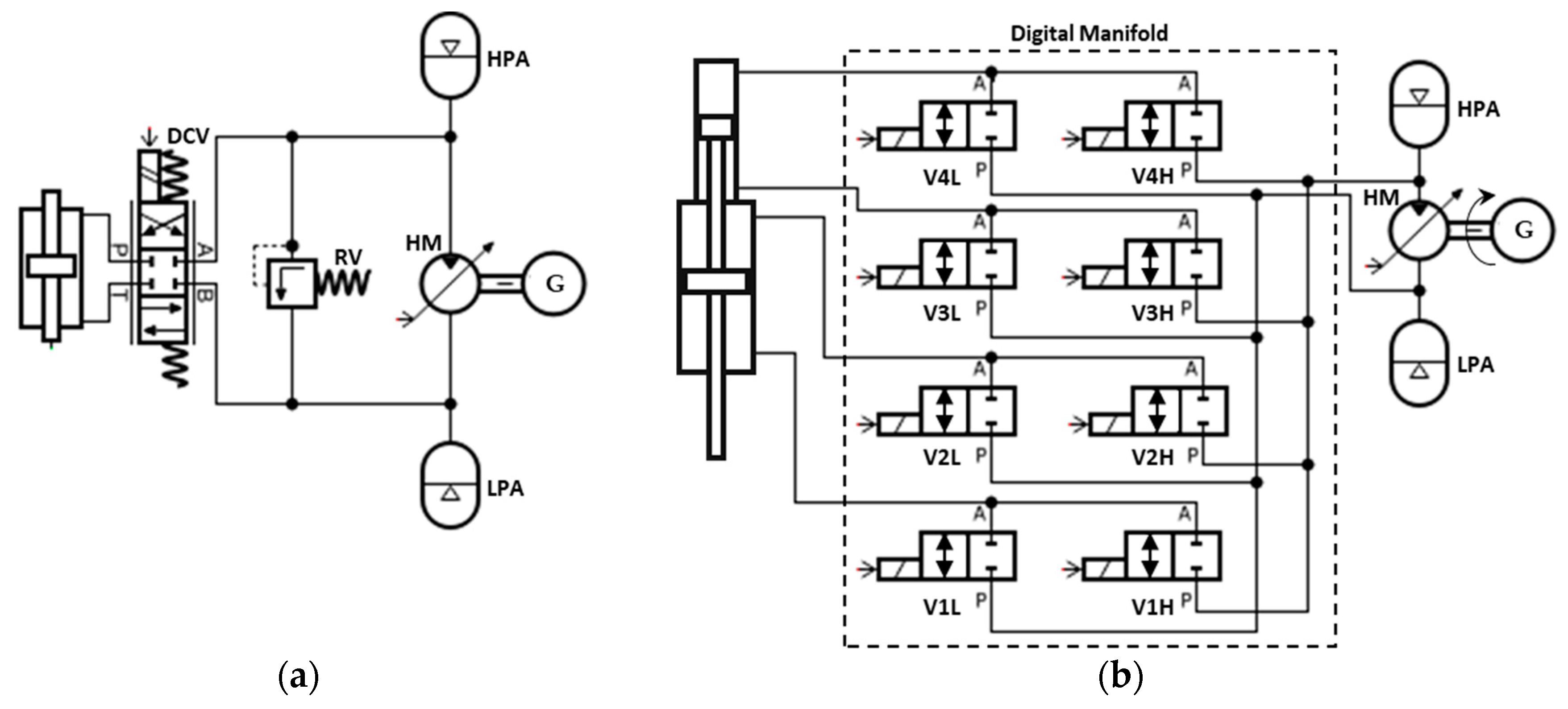
A hydraulic PTO system based on the directional control valve also has been proposed for the wave energy conversion system. For example in [
61], the concept of CP-Type IV in
Figure 4b was modified by replacing the four-valves system with the single directional control valve in the rectification module, while the rest of the components remains the same as the CP-Type IV as presented in
Figure 6a. In this concept, a three-position directional valve is added in the hydraulic PTO system, where the middle position of the valve is in idle or declutched mode, and its input ports are directly connected to the hydraulic actuator chambers as presented in
Figure 6a [
61]. Meanwhile, the output ports are connected to the high-pressure and low-pressure lines of the hydraulic PTO system. The controllability of these concepts is higher compared to the concepts based on the check valves system. In this concept, advanced control of the electronic controller can be utilised by the directional control valve to connect the hydraulic actuator chamber either to high-pressure or low-pressure lines of hydraulic PTO system.
In [
46], a multi-chamber with multiple directional control valves hydraulic PTO system has been proposed. In this concept (CP-Type XII), a four-chamber hydraulic cylinder actuator is attached to a rectification module, which consists of eight on/off directional valves, as presented in
Figure 6b. These valves connect to each hydraulic chamber, which has different pressures because of the different effective working areas. This PTO concept allows a variable force of a hydraulic cylinder actuator converted to a constant pressure system without using throttling-based control [
91]. Through the arrangement of valves, 16 different combinations of the chamber can be achieved, producing 16 different available PTO forces. Thus, during a wave period, the PTO force is varied discretely. This PTO concept has been numerically and experimentally evaluated in [
46], where the efficiency of 90% was feasible. This concept also has been investigated in several studies, such as in [
48,
92].
2.2.4. Constant-Pressure Hydraulic PTO Based on Hydraulic Transformer Concepts
There is another concept of constant-pressure hydraulic PTO system, where a variable displacement hydraulic pump/motor with four operation modes known as the hydraulic transformer is utilised as a rectification module [
45].
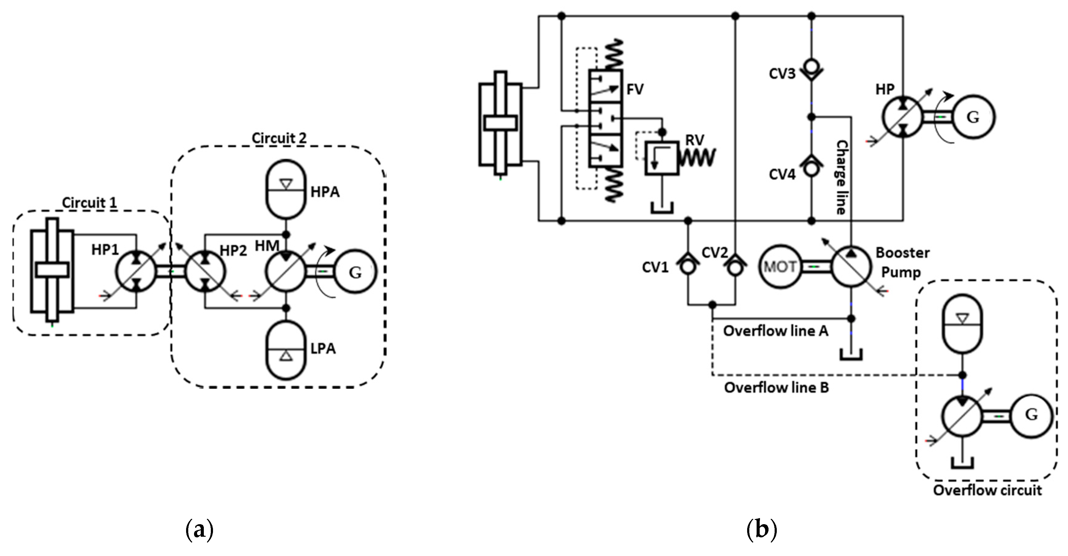
Figure 7a presents a basic hydraulic PTO concept based on the hydraulic transformer rectification module. Based on the figure, the symmetrical hydraulic actuator module is connected to the hydraulic pump/motor HP1 in the first circuit, while the generator module is connected to the hydraulic motor HP2 in the second circuit. Circuit one and two are combined by mechanically back-to-back coupling of HP1 and HP2. The bi-directional fluid flow from the hydraulic actuator is converted by hydraulic transformer HP1 into a unidirectional high-speed rotation for driving a generator module. Pressure control is performed by regulating the swash-plate angle of hydraulic transformer HP2 in order to control the forces applied to the WEC device. This hydraulic PTO based on the hydraulic transformer is more advanced since it not only can rectify bidirectional flows but also can control the hydraulic pressure of the PTO system. However, this hydraulic transformer concept is less efficient since both pumps are operating in back-to-back position, thus the performance of the pumps depends on each other.
In
Figure 7b, a modified concept of hydraulic PTO system based on the hydraulic transformer concept is presented [
93]. This concept is an architectural evolution from the basic concept (CP-Type XII) presented in
Figure 7a. This concept (CP-Type XIII) consists of a symmetrical hydraulic cylinder actuator directly linked to a hydraulic pump/motor which is coupled with an electrical generator. Similar to CP-Type XII, the bidirectional flows are converted to unidirectional flow by hydraulic pump/motor. A closed-loop flushing and relief valves module is added between the actuation module and generation module to flush heated hydraulic fluid and dirt particles in the PTO system during the operation, thus increases the life span of the PTO system. In this concept, the charging module consists of a booster pump, and the oil-tank is also added to refill the fluid in the hydraulic PTO system because of the leakage flows of the hydraulic cylinder actuator and the four-quadrant pump [
62]. Furthermore, the overflow module also is included in this concept to by-pass over-pressurised flow in the main hydraulic PTO system into the oil-tank. However, through this mechanism, the energy contained in overflow fluid would be wasted. Therefore, the CP-Type XII concept with an extra overflow module (dotted-square) has been proposed in [
94]. The overflow module consists of a booster pump, accumulator and an oil-tank is added to convert the overflow fluid energy into useful electrical energy and directly improves the energy production from the hydraulic PTO system.
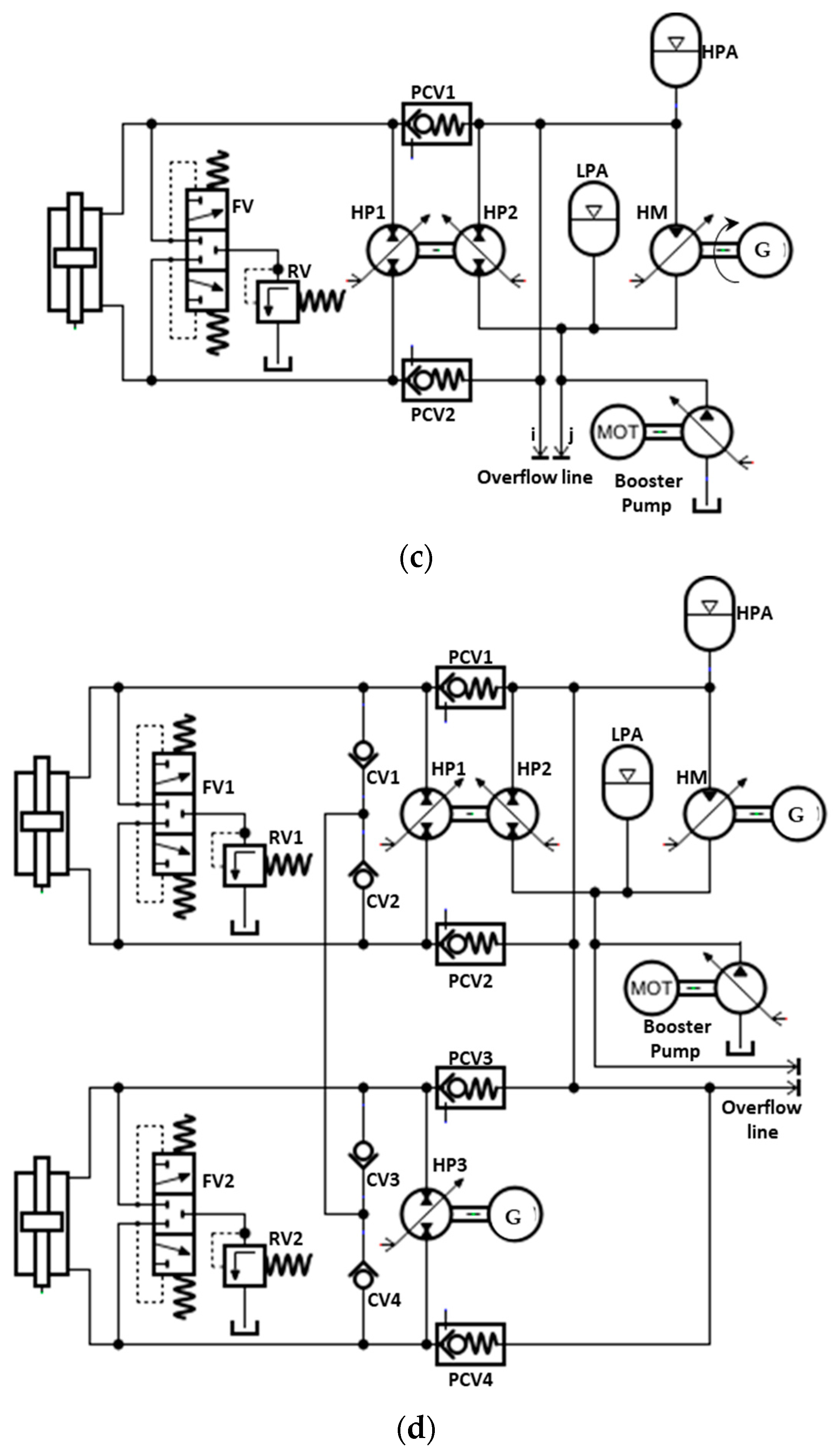
Apart from that, the concept which combines the benefits of CP-Type XII and CP-Type XIII concepts also has been proposed, as presented in
Figure 7c [
45]. In this concept (CP-Type XIV), the CP-Type XII concept was altered by adding the by-pass line and the piloted-check valves (PCV1 and PCV2) in order to bypass the back-to-back hydraulic transformer module during the peak operation. In certain circumstances, the valves PCV1 and PCV2 are also piloted to close the bypass line to deliver reactive power produces by a hydraulic transformer to the hydraulic actuator module. In addition, the flushing valve, overflow line and the charge module are also considered in this concept. Besides that, further studies, according to the CP-Type XIV concept, has been carried out in [
62,
95]. In these studies, the CP-Type XIV concept has been modified by connecting the overflow line to the secondary hydraulic PTO system in parallel, as presented in
Figure 7d. In this concept (CP-Type XV), the secondary hydraulic PTO system is only used during the reactive mode, which means, during adjusting the phase velocity of the WEC device is in the primary hydraulic PTO system. During reactive operating mode, the valves PCV1 and PCV2 is closed letting the fluid flows subjected to the pressure difference of high-pressure and low-pressure circuit. The main advantage of this concept is the size of the several hydraulic PTO system components such as hydraulic pump, generator and et cetera, can be reduced. In addition, the charging operation of the booster pump, which required high power consumption can be minimised.
3. Review of Control Strategies Used in Hydraulic PTO System
The development of reliable WEC with an efficient hydraulic PTO system is the main challenge for the wave energy conversion system because of the unpredictable nature of the natural environment and device limitations [
45]. The power generated by the WEC with a hydraulic PTO system is influenced by many parameters, and its optimisation can be performed during the design stage or actual sea operation using dynamic control strategies [
14]. The advanced control strategies can be accomplished in the actual operation of a wave energy conversion system using mechanical or electrical control mechanism in a hydraulic PTO system. The optimal design control strategy can increase the energy yield and prolong the lifetime of the PTO system [
96]. Recently, a variety of dynamic control strategies have been proposed and investigated to optimise the power extraction WEC system. Identifying the specific characteristics of different control strategies is necessary to understand the advantages, limitations, and complexity associated with the implementation. Generally, categorising the control strategies is difficult since there are a variety of ways to develop and implement an individual strategy [
97].
Figure 8 shows the classification of control strategies for wave energy conversion according to the different criteria. The most popular classification is based on the power flow, namely, the resistive control and reactive control [
14]. The resistive control is also known as passive control, which only involves the resistive (damping) force and does not handle reactive power flow. Several strategies, i.e., latching control [
98], clutching and declutching control [
99], can be classified as resistive control strategies. On the other hand, the reactive control known as active control, which involves damping and stiffness force tuning.
Moreover, the control strategies also can be categorised based on the parameters optimisation event such as offline and online optimisation [
100,
101]. The offline optimisation control strategies are defined as the control strategies that optimise its control parameters according to the previous or future (forecasted) ocean waves data [
100]. Frequently, the optimal parameter values can be found through preliminary simulations. The offline control strategies are prescribed and will not be adapted because of the changing environment. Meanwhile, online control strategies are defined as the control strategies which can perform an optimal control action at every time instant such that it is expected to maximise energy generation over a short time [
100]. The online control strategies are adaptive to the changing environment. Some control strategies in the references can be categorised into this group. Finally, the control strategies also can be classified as causality properties, i.e., causal and non-causal. Causal-based control strategies require past inputs data, while the non-causal-based control strategy requires future input data (from the forecasting model) [
102].
For WEC with a hydraulic PTO system, the optimal reference signal generated by advanced control strategies can be accomplished by controlling several main components in the hydraulic PTO system, i.e., hydraulic cylinder, valve, accumulator, hydraulic motor and electric generator. The following subsection presents the review of control mechanisms implemented in the hydraulic PTO system of the wave energy conversion system.
3.1. Hydraulic Accumulator with an Active Control Valve Mechanism
A control strategy that involves a hydraulic accumulator with an active control valve mechanism is the simplest and most used approach to control the hydraulic PTO force. For example, in [
84], a phase control strategy has been proposed by adding extra control accumulators with the active control valve in the typical hydraulic PTO system, as presented in
Figure 4f. A special control algorithm for controlling the active control valves operation was proposed in order to control the high-pressure fluid flow from the accumulator and hydraulic motor [
84]. The simulation result shows that this approach dramatically improves the performance of a wave energy conversion system. The effectiveness of this approach also has been evaluated against different opening instants of activation of the control valves, and the simulation results demonstrate that the application of this approach is most time beneficial.
Meanwhile, in [
65], a control strategy based on a sea-state maximum power point tracking (MPPT) control algorithm was invented for utilising on a typical submerged WEC coupled typical hydraulic PTO system as presented in
Figure 3b. In this approach, the MPPT control based on a simple gradient-ascent algorithm was created to control the hydraulic PTO force. The accumulator with an active control valve near the hydraulic cylinder actuator is used to control the damping force of the buoy. The WEC simulation model based on Carnegie’s CETO system was developed to evaluate the robustness of the control strategy. The simulation result demonstrates that the proposed MPPT damping control strategy is effective in improving the efficiency of the tested wave energy conversion system by 1–6%.
In another example in [
72], an accumulator control approach based on the pressure drop database as the feedback control (PDDFC) to stabilise the electrical power output of a specified level is proposed. The PDDFC method eliminates the inconvenient periodical peak pressure impulse by regulating the active control valve of the hydraulic accumulator. Compared with the previous sophisticated control strategies, this approach can maintain the power output of the electrical generator more stably for various operating conditions. In addition, the experimental test also has been conducted to evaluate the effectiveness of the proposed control approach, and the results demonstrated that the output power of the hydraulic PTO system with this control approach is significantly stable. Also, the power quality and generation efficiency of the hydraulic PTO system is improved. Other examples of hydraulic PTO force control strategy based on a hydraulic accumulator with an active control valve are presented in [
47,
67,
72,
75,
88,
103].
3.2. Hydraulic Cylinder with an Active Control Valve Mechanism
Another approach for controlling the PTO force is using a hydraulic cylinder actuator with an active control valve. For example, a simple approach for controlling hydraulic PTO force is using the declutching method, which has been applied in [
99]. In this approach, a PTO force of a simple hydraulic PTO system, as presented in
Figure 6a, is controlled by switching off and on alternatively the hydraulic actuator from the hydraulic PTO system using 3-way directional valve. The command based on the Pontryagin principle has been used to compute the control law for maximising the extracted energy from the ocean waves and generate the references for the directional control valve. This control approach has an advantage in which it requires only a single active valve control mechanism compared to the other control method, which involves a more sophisticated control mechanism. The proposed control approach has been evaluated, and the numerical simulation result indicates that the control approach can lead to higher energy absorption, either in regular and irregular ocean waves compared to the pseudo-continuous control method.
Apart from that, the combination of active valves operation, such as in a typical hydraulic PTO concept presented in
Figure 6b, also can be used to control the hydraulic PTO force as investigated in [
48,
91,
104]. For example, in [
91], the multi-level control strategies have been invented for typical WEC with hydraulic PTO concept presented in
Figure 6b. In the proposed control strategies, the hydraulic PTO force reference is optimised at several stages, since the performance of wave conversion system depends on efficiencies of the WEC device in the hydraulic PTO system. In the first stage optimisation, the wave power extraction algorithm (WPEA) is created to calculate the maximum energy expected to be generated by WEC device according to the sea-state condition. Meanwhile, in the second stage of optimisation, the force switching algorithm (FSA) is invented as a supervisory controller to provide an optimal reference signal for secondary controllers (combination of by-pass valves) to be switched on or off according to the force references generated by WPEA. The results from the simulation studies indicated that using proposed control strategies, the overall efficiency of a typical hydraulic PTO system can be achieved up to 80%.
Furthermore, a similar concept of control strategies in [
91] also has been implemented in a multi-chamber hydraulic actuator-based PTO system [
104]. In this study, the WPEA based on the model predictive control (MPC) principle has been invented to maximise the wave energy production by cleverly manipulating the PTO force. The MPC control strategy allows online optimisation which is able to control the hydraulic PTO system directly during the energy maximisation process. However, the performance of the MPC control strategy depends on the accuracy of the wave prediction algorithm. Based on the investigation study results, the author has concluded that WPEA based on MPC principles is possible and favourable for utilising in a discrete fluid of hydraulic PTO system for the wave energy conversion system. In [
48], a comparison study of the different types of WPEA has been carried out. In this study, six different kinds of WPEA from previous literature, such as Singular Arc control (SA), proportional-derivative (PD) control, MPC, pseudo-spectral (PS) control, proportional-derivative complex conjugate control (PDC3) and shape-based (SB) control has been compared. From the simulation results under theoretical test consideration, where the ideal PTO system is used, the SA control strategy has shown the greatest performance during energy extraction. However, the situation is contrasting when hydraulic PTO system is used instead of the ideal PTO system. From the presented results, the execution of the SA control strategy with the hydraulic PTO system is the worst, while the MPC control strategy shows the greatest achievement among the six control strategies [
48].
3.3. Hydraulic Transformer or Hydraulic Motor with a Digital Control Mechanism
Apart from that, the displacement of the hydraulic transformer or hydraulic pump/motor also can be adjusted to control the PTO force. For example, in [
45], a hydraulic transformer control mechanism in a typical hydraulic PTO system presented in
Figure 7c is utilised to control the pressure and directly control the force of the hydraulic PTO system within an acceptable nominal value. In this approach, a proportional–integral–derivative (PID) controller is utilised to perform active or reactive control of the WEC device. A PID controller is used to provide an appropriate reference control signal to the secondary controller of the hydraulic transformer, which is a digital displacement controller. A PID controller compares the pressure of the high-pressure line to the desired pressure level in order to determine the optimal reference value for the digital displacement controller. Simulation result from this study indicates that this approach is suitable and effective during most energetic sea states, where the hydraulic PTO system operates with an estimated efficiency of 71%. Furthermore, in other approaches, another controller such as a fuzzy controller [
62] and proportional-integral (PI) controller [
78] also have been proposed to control the speed of the hydraulic motor.
3.4. Control Mechanism in Conditioning Module
Currently, most of the researchers are focusing on controlling the hydraulic PTO system using mechanical components, as described in the previous subsection. However, this mechanical-based approach has a drawback such as response time problems which can cause complexity in the control system. Also, the control systems based on the mechanical mechanism demand for high-technology components such as a digital displacement hydraulic motor, digital mechanical sensor and et cetera, that is reasonably expensive. Therefore, the control approach of the hydraulic PTO system based on electrical mechanism can be a reasonable alternative to mechanical-based control approaches.
For example, in [
105], a control strategy of a pulse width modulation (PWM) rectifier to maximise the efficiency of the typical hydraulic PTO system (CP-Type II concept) is proposed. This control strategy consists of speed feedback control in the outer loop and current decoupling control in the inner loop adopted to the rectifier component in the conditioning module. An outer control loop, the maximum efficiency converting (MEC) algorithm is developed for calculating the optimal speed reference based on the accumulator pressure. The given reference speed and actual speed signal from the MEC and electrical generator is computed by the PID controller and uses as input for the inner loop control. In an inner control loop, the PI controller is utilised to determine the current decoupling control, and the space vector algorithm is used to generate the PWM reference control signal for rectifier. This approach has been experimentally evaluated, and the experiment results demonstrated that the generator speed was successfully controlled during intermittent of the ocean wave.
5. Conclusions
The ocean wave is one of the most significant untapped renewable energy sources. The high potential of this renewable energy source and the rapid growth of wave energy conversion technology are driven by the need to bring this technology in line with the existing fossil fuel-based power generation. Recently, numerous studies have been conducted on energy extraction and conversion from ocean waves using various kinds of concepts. Many types of power take-off (PTO) system have been developed, i.e., based on turbine (air and hydro), direct-mechanical drive system, direct-electrical drive and hydraulic system. Hydraulic PTO system is the most appropriate PTO mechanism for conversion of wave into electrical power, especially for the WAB wave energy conversion system because of its excellent characteristics, i.e., well-adapted to low-frequency and larger power waves.
This review presented the latest concepts of hydraulic PTO system used in the wave energy conversion system, which can be a useful reference to researchers, engineers and inventors. Generally, the hydraulic PTO system can be classified into a constant-pressure and variable-pressure system. The concepts in a variable-pressure category are simple. However, they have limited controllable parameters, which can lead to poor performance. Thus, the concepts based on the constant-pressure hydraulic PTO system are the alternatives to the variable-pressure hydraulic PTO system, and they are more used rather than the concept based on the variable-pressure hydraulic PTO system. Since there are a variety of concepts in this group, they can be classified based on its rectification modules such as two-check valves concept, four-check valves concept, directional control valves concept and hydraulic transformer concept. The PTO concept based on two check valves system is ineffective because of the single-acting motion of the hydraulic cylinder actuator, which can waste the part of the extracted power. The concepts based on the directional control valves and hydraulic transformer are most efficient since they can be adapted with many optimal control strategies.
Furthermore, the control mechanisms of the hydraulic PTO system also have been reviewed and discussed in this paper. The power generated by the WEC with a hydraulic PTO system is influenced by many parameters. Its optimisation can be conducted during the design stage or actual sea operation using dynamic control strategies and the control mechanism of a hydraulic PTO system. In this paper, various kinds of control strategies integrated with control mechanisms using specific components in hydraulic PTO system such as active control valve (directional control valve), hydraulic transformer, accumulator, booster pump and et cetera, have been discussed. The control strategies based on the model predictive control (MPC) integrated with an active valve control mechanism is simple, and it shows the most excellent performance compared to the other control approaches. This approach increases the overall efficiency of a typical hydraulic PTO system for up to 80%.
Apart from that, the benefits and challenges of the hydraulic PTO system also have been discussed. Several significant advantages of hydraulic PTO system have been revealed, for example, it can be developed using the components adapted from standard commercial applications. In addition, the hydraulic PTO system also can be effective to tune the WEC device according to the ocean wave condition in order to maximise the energy extraction. Despite being able to provide excellent benefits, several challenges of hydraulic PTO system also have been revealed, for example, its regularly required system maintenance to prevent leakage occurrence, which can harm the marine environment in case a leakage occurs.

 ,
, 


