Article

Energy Management of Low-Pressure Systems Utilizing Pump-Unloading Valve and Accumulator

School of Mechanical Engineering, Purdue University, 610 Purdue Mall, West Lafayette, IN 47907, USA
*
Author to whom correspondence should be addressed.
Energies 2019, 12(23), 4423; https://doi.org/10.3390/en12234423
Submission received: 31 October 2019 / Revised: 17 November 2019 / Accepted: 18 November 2019 / Published: 21 November 2019

Abstract

:
In the context of improving energy efficiency and fuel consumption of mobile hydraulic equipment, it is important to analyze all the sources of power loss occurring within the hydraulic systems. While plenty of analyses have been performed on the working implements and the main transmission systems, very little attention has been paid to low-pressure (LP) systems until recently. LP systems are required on closed-circuit hydraulic systems to replenish losses, provide cooling flow, and maintain a pilot pressure necessary to operate hydraulic control valves and variable displacement units. It is shown that these circuits, which are often thought to have minimal impact on power consumption, actually cause significant, continuous power loss. A new method of power savings in these circuits is investigated through management of charge pump flow by application of an accumulator-sense pump-unloading (ASPU) valve. This work further proposes the combination of a split LP architecture with an ASPU valve. Three systems are simulated using Simcenter Amesim® and MATLAB/Simulink®. Using realistic duty cycles and unit loss models on a circuit for mobile off-road hydraulic equipment, it is shown that a standard LP system can consume about 5 kW of power. Power savings of up to 65% over a standard LP system are demonstrated by the proposed architecture.

1. Introduction

Hydrostatic transmissions are powerful, flexible means of power distribution. However, current state-of-the-art technologies have many opportunities for improvement on overall energy efficiency. Mobile fluid power systems currently consume up to 6.5% of the energy of the total transportation sector, but exhibit efficiencies potentially as low as 21.1% as provided by an Oak Ridge National Laboratory report, and 30% as estimated by an anonymous manufacturer [1]. In the pursuit of minimizing fuel consumption and emissions while maximizing efficiency, attention must be paid to all power consumption in hydraulic systems. One very common, yet frequently overlooked, power consumer is the low-pressure (LP) system. Low-pressure systems are a necessary part of closed-circuit hydraulic systems. These circuits are required in closed-circuit applications to provide cooling flow and make-up flow to replenish unit losses in the circuit. They must maintain a minimum acceptable pressure in the return line to prevent cavitation. LP systems also must maintain pilot pressure for hydraulically actuated variable-displacement unit control systems [2]. LP circuits can contribute to continuous power losses because they are often implemented with a fixed displacement pump, providing constant flow, while excess is normally returned to the tank over a relief valve at system pressure. These systems can be viewed as a type of constant-pressure system, given their requirements for maintaining a reference pressure level within the main transmission system.

1.1. Constant Pressure Systems

In the field of hydraulic control systems, constant pressure hydraulic systems are usually referred to as a type of hydraulic drive system that provides power to actuators by means of a supply that operates at a constant pressure, regardless of the amount of flow (at least up to the maximum achievable flow rate). These systems are often used in large equipment, such as aerospace and marine applications, but also quite often for a direct torque control of hydraulic motors, such as in hydraulic propellers or fan drives. They benefit from being simpler than other architectures for hydraulic drives based on variable supply pressure, such as open center systems or load sensing systems. They also usually deliver fast response times at the cost of poor efficiency at lower loads due to valve throttling losses [3,4]. Constant pressure systems appear in various architectures, four of which are shown in the simplified schematics of Figure 1. Figure 1a is one of the most common constant pressure systems. A pump provides flow through a check valve to charge an accumulator. An unloading valve is controlled directly by the accumulator pressure, relieving the pump to tank when the desired pressure level is reached. Figure 1b, a pressure-compensated pump, is commonly found in industrial applications. The displacement mechanism maintains correct flow to provide a constant pressure to the users. Figure 1c shows a new constant pressure system introduced by Vukovic et al. for mobile equipment. A variable displacement pump controls the state of charge of two accumulators, one high- and one medium-pressure, by means of a directional valve to supply two pressure rails. This would be implemented with a series of switching valves and proportional valves to create a multitude of supply pressures based on current loading conditions. This architecture provides many benefits such as energy recovery and decoupling actuator demand from engine speed [5].

1.2. Low Pressure Systems

A standard low-pressure supply is typically a fixed displacement gerotor pump maintaining a constant flow at relief pressure, shown in Figure 1d; however, other types of fixed displacement pumps such as vane or external gear pumps are utilized as well. This architecture is reliable, effective, inexpensive, and largely unchanged in most applications, typically closed-circuit hydrostatic transmissions.
Typically, the size of the charge pump is determined by static sizing methods under worst-case scenarios of flow demand [2]. This leads to an LP system that is oversized for the majority of the drive cycle, causing unnecessary power consumption by exceeding the flow requirements of the system. Further, as the charge pump must maintain pressure for the unit control systems as well as provide for flushing flow replenishment, power losses through unnecessary flow are exacerbated as they leave the system at higher-than-necessary pressure. Hydraulic power lost over the relief valve can be calculated by Equation (1).
P = Q R · p R
Theoretical alternatives to a fixed displacement pump do exist. Pressure-compensated vane pumps, implemented as in Figure 1b, would be an option, particularly for small-size charge circuits. However, they suffer from high hydromechanical losses when operating at the low pressures expected in a charge circuit [6]. These are also costlier and less reliable than their fixed displacement counterparts. Zavadinka and Grepl proposed implementation of a variable-displacement charge pump controlled with a thermostat to limit flushing flow to only what is necessary, realizing potential energy savings of 2.77 kW (38%) on a combine harvester [7].
Keller proposed an alternative architecture, where the pressure for the unit control systems was provided by a tertiary pump smaller than the secondary charge pump. The control system pump minimized flow at the higher control pressure of 20 bar while the charge system pump provided replenishing and cooling flow at 11 bar [8]. The proposed system made use of an accumulator to account for differential flow across a hydraulic cylinder to minimize charge pump size. His novel LP system achieved a 36% reduction in power requirements when compared to a traditional architecture with an accumulator [8].

2. Proposed Architecture

2.1. Accumulator-Sense Pump-Unloading Valve

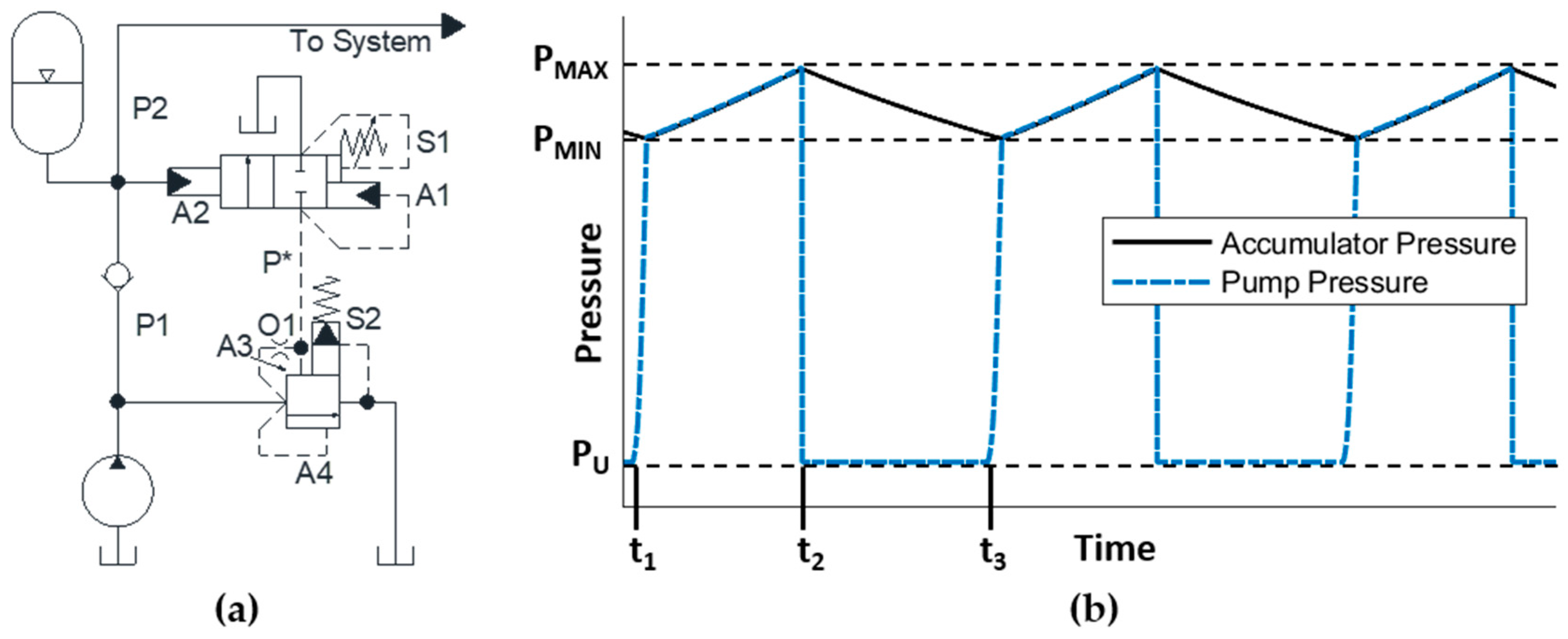
A solution to some of the challenges faced by low-pressure circuits is to implement a method of flow control, directing flow at the pressure of the LP circuit only when necessary. This can be achieved using an accumulator-sense pump-unloading (ASPU) valve. An ASPU valve is a manifold that detects the state of charge of an accumulator and maintains it within a specified range of pressure values by unloading the pump to tank at a lower pressure when the accumulator pressure reaches its upper limit. Often, these are used on high-pressure circuits with heavy but intermittent duty cycles, or are used to maintain a narrow pressure range in constant pressure systems [9]. Figure 2a shows one ASPU valve configuration. There are two valves: the accumulator sensing valve (top) controls pilot pressure sent to an unloading valve (bottom) by sensing the state of charge of the accumulator. The unloading valve unloads pump flow to tank when its pilot is vented by the sensing valve. Neglecting flow forces, during charging p * = p 1 and a force balance on the sensing valve is:
  F = p 2 A 2 p 1 A 1 S 1
During discharging, p * is drained to tank so the force balance reduces to:
  F = p 2 A 2 S 1
Therefore, maximum pressure is determined by:
p 2 = p 1 = p M A X = S 1 A 2 A 1 ,
and minimum pressure is determined by:
p 2 = p 1 = p M I N = S 1 A 2
Unloading valve cracking pressure is:
p U = p * A 3 + S 2 A 4
Operation is described as follows, see Figure 2a. The accumulator sensing valve (top) maintains pressure p * on the unloading valve (bottom) via a pilot line, such that the unloading valve cracking pressure is maintained above circuit pressure. The sensing valve spring S 1 plus pilot line p * provide cracking pressure set to p M A X on the sensing valve. On the interval of t 1 t 2 , Figure 2b, flow travels from the pump through the check valve and supplies both the system and the accumulator. Once the accumulator is charged to p M A X at t 2 , the sensing valve opens, venting the pilot line of the unloading valve. Flow is unloaded at unloading valve cracking pressure S 2 / A 4 while the circuit maintains pressure due to the check valve and discharges the accumulator into the system. When the accumulator reaches p M I N at t 3 , the sensing valve closes, providing pilot pressure again on the relief valve, recharging the accumulator. Implementation of this does require an acceptable variation in pressure ranges, the size of which is set by the valve reset differential, and the timing set by the accumulator volume. This is not unreasonable. Some minor variation of LP pressure exists in standard LP systems due to the non-ideal behavior of their relief valves.

2.2. Low Pressure Circuit Implementation

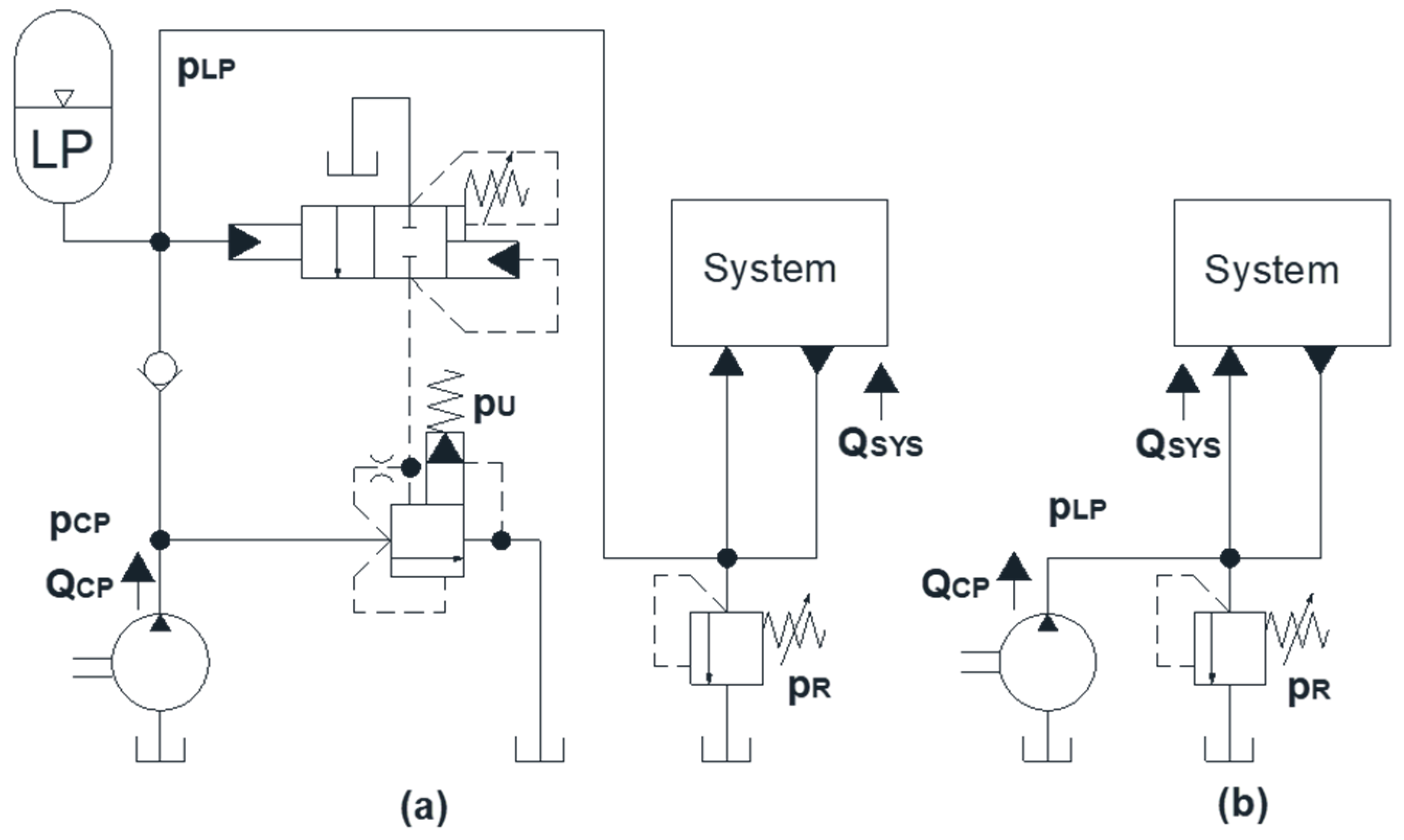
An application of an ASPU valve to a low-pressure circuit is shown in Figure 3a, compared to a standard low-pressure circuit in Figure 3b. This architecture can be used to prevent the charge pump from providing excess flow over the relief valve at charge pressure, instead directing it over an unloading valve. Due to the reserve in the accumulator, this system also allows the charge pump to be downsized, further reducing power consumption.
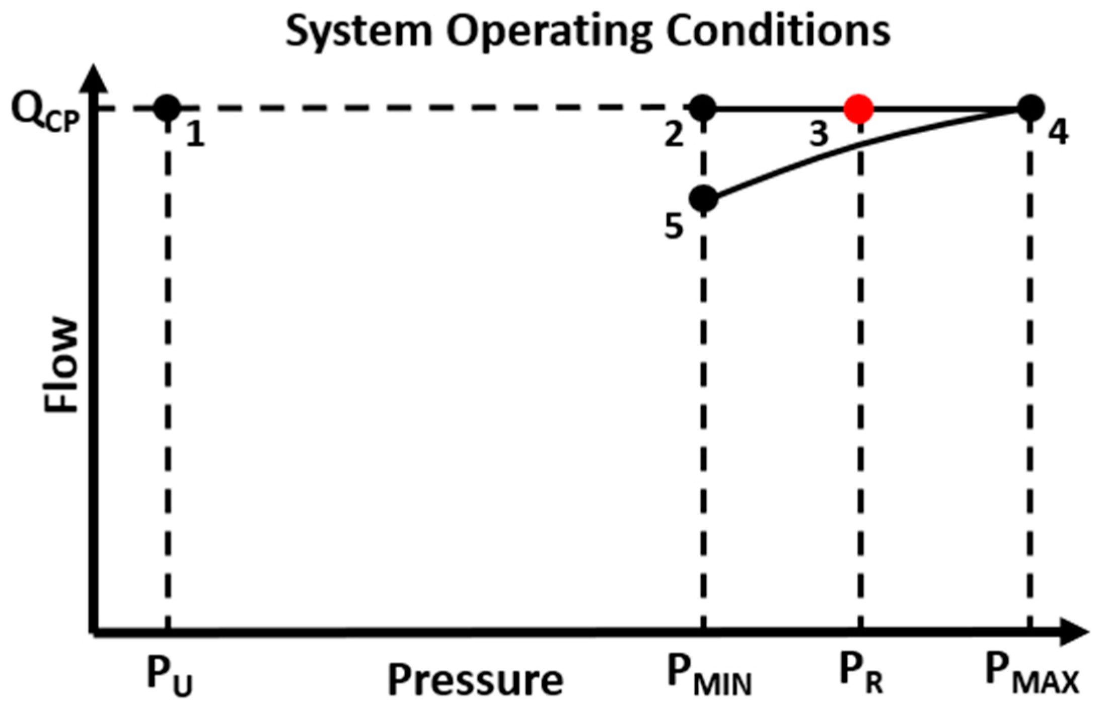
Figure 4 shows the operating points of an ASPU-controlled LP system and a traditional LP system. The traditional system provides a constant flow, Q C P , at a virtually constant pressure, p R . Therefore, it is limited to operating at its corner power, point 3 shown in red. An ASPU pump will work at varying pressure ranges, although it still provides a constant flow. Referring to the cycle shown in Figure 2b, and the operating points in Figure 4, during the t 1 t 2 interval, the pump will work in a range between points 2 and 4. During the t 2 t 3 interval, the pump will work at point 1. Hydraulic flow from the accumulator on the t 2 t 3 interval occurs along the curve between points 4 and 5. Energy savings are therefore achieved by allowing the pump to only work at LP pressure when necessary and reverting to unloading pressure otherwise. For the ASPU system, p R is set to a substantially high pressure as to prevent relief flow under normal operating conditions. It should be noted that p U , p M I N , and p M A X are variable based on desired performance and system requirements. For illustrative and comparative purposes, p M I N and p M A X are initially chosen such that the standard LP pressure, p R is their average.
For a fixed displacement charge pump providing flow Q C P , assuming the charge circuit maintains pressure at the relief setting p R and neglecting pump losses, a standard low-pressure circuit will consume hydraulic power:
P H Y D = Q C P · p L P = Q C P · p R
Using the polytropic process equation and representing accumulator precharge as p 0 and volume at precharge as v 0 , the state of the accumulator gas can be determined by:
p 0 V G , 0 n = p 1 V G , 1 n = p 2 V G , 2 n
Total work done on the accumulator gas during charging can be calculated by:
W G , 1 2 = V G 1 V G 2 p d V
Substituting pressure as a function of volume and integrating, accumulator work is:
W G , 1 2 = [ p 1 V G 1 ( v 1 n 1 n ) ] v 1 v 2
W G , 1 2 = p 0 V G , 0 1 n [ ( p 0 p 2 ) 1 n n ( p 0 p 1 ) 1 n n ]
To relate terms independent of time and assuming that required charge flow leaving the LP circuit is independent of pressure, total hydraulic volume change can be related to accumulator gas volume change over the charging interval t 1 t 2 as:
Δ V H , 1 2 = Δ V G , 1 2 = ( V G 2 V G 1 ) = ( Q C P Q S Y S ) ( t 2 t 1 )
so, the time interval can be defined entirely in terms of flow rates of pressures (correcting for fluid volume sign convention):
( t 2 t 1 ) = V G , 0 Q C P Q S Y S [ ( p 0 p 1 ) 1 n ( p 0 p 2 ) 1 n ]
Work delivered to the main system during the charging interval can therefore be calculated using Equation (11) similarly, and correcting for fluid volume sign convention:
W S Y S , 1 2 = Q S Y S Q C P Q S Y S p 0 V G , 0 1 n [ ( p 0 p 1 ) 1 n n ( p 0 p 2 ) 1 n n ]
Total work delivered by the charge pump during charging is shown by:
W C P , 1 2 = Q C P Q C P Q S Y S p 0 V G , 0 1 n [ ( p 0 p 1 ) 1 n n ( p 0 p 2 ) 1 n n ]
Work delivered by the accumulator to the system during the discharge cycle t 2 t 3 is calculated again using the polytropic process equation:
W S Y S , 2 3 = p 0 V G , 0 1 n [ ( p 0 p 1 ) 1 n n ( p 0 p 2 ) 1 n n ]
and the work required by the pump which is unloaded to tank at p U during this cycle is:
W C P , 2 3 = Q C P p U ( t 3 t 2 ) = Q C P p U V G , 0 Q S Y S [ ( p 0 p 1 ) 1 n ( p 0 p 2 ) 1 n ]
The total work required of the ASPU system over one duty cycle is the sum of the pump work over charging and discharging cycles:
W C P , 1 3 = W C P , 1 2 + W C P , 2 3
The work required of a standard LP charge pump over the same length of time can be expressed similarly to Equations (15) and (17) by defining the time interval t 1 t 3 in terms of pressure and initial volume, as in Equation (12):
W C P , S T D = Q C P p R ( t 3 t 1 ) = Q C P 2 p R V G , 0 Q S Y S ( Q C P Q S Y S ) [ ( p 0 p 1 ) 1 n ( p 0 p 2 ) 1 n ]
and the work delivered by the standard LP system to the main hydraulic system per time is:
W S Y S ,   S T D = Q C P p U ( t 3 t 2 ) = Q C P p R V G , 0 Q C P Q S Y S [ ( p 0 p 1 ) 1 n ( p 0 p 2 ) 1 n ]
Hydraulic efficiency of an LP system can be defined as the fraction of work delivered to the main circuit compared to the work required of the charge pump:
η L P = W S Y S , 1 3 W C P , 1 3
Therefore, the hydraulic efficiency of the ASPU system can be calculated by:
η A S P U = Q S Y S p 0 [ ( p 0 p 1 ) 1 n n ( p 0 p 2 ) 1 n n ] Q S Y S p 0 [ ( p 0 p 1 ) 1 n n ( p 0 p 2 ) 1 n n ] + p U ( 1 n ) ( Q C P Q S Y S ) [ ( p 0 p 1 ) 1 n ( p 0 p 2 ) 1 n ]
whereas the efficiency of a standard LP system reduces to flow fraction:
η S T D = Q S Y S Q C P
Comparing energy consumption of the two systems leads to the following:
W A S P U W S T D = Q S Y S p 0 [ ( p 0 p 1 ) 1 n n ( p 0 p 2 ) 1 n n ] + p U ( Q C P Q S Y S ) ( 1 n ) [ ( p 0 p 1 ) 1 n ( p 0 p 2 ) 1 n ] Q C P p R ( 1 n ) [ ( p 0 p 1 ) 1 n ( p 0 p 2 ) 1 n ]
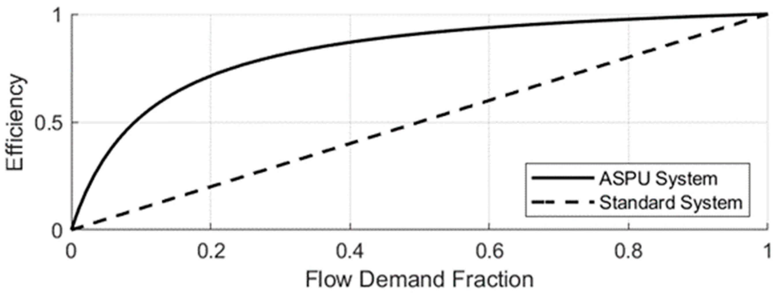
These energy consumption and efficiency comparisons lead to some important conclusions. Firstly, according to Equations (22) and (23), as the fraction of flow demand by the system approaches unity, each system becomes more hydraulically efficient. This indicates that the most energy-efficient charge pump is one that is sized to deliver the exact amount of flow demanded by the system. However, this is not feasible. A charge pump sized for average conditions will fail at higher demand and one sized for high demand will deliver excess flow under average conditions. Therefore, a standard LP system with a charge pump sized for all conditions will require more energy than is necessary for the functions of the LP system. Equation (22) shows that an equivalent size charge pump in an ASPU system will always be more energy-efficient, given the same conditions. Figure 5 illustrates this principle. Given fixed operating conditions, efficiency is largely a function of p U .
Equation (24) gives fraction of work required by the ASPU system versus a standard system. As system flow demand approaches the flow of the charge pump, the work requirement of the ASPU system approaches the work of the standard system. This shows diminishing returns as the charge pump is sized nearer to system demand. Conversely, as flow demand approaches 0, the fraction approaches p U p R , indicating that an ASPU system will scale energy consumption according to flow demand. Therefore, given identical charge flow and system demand, energy saving potential can be calculated solely as a function of working pressure ranges.
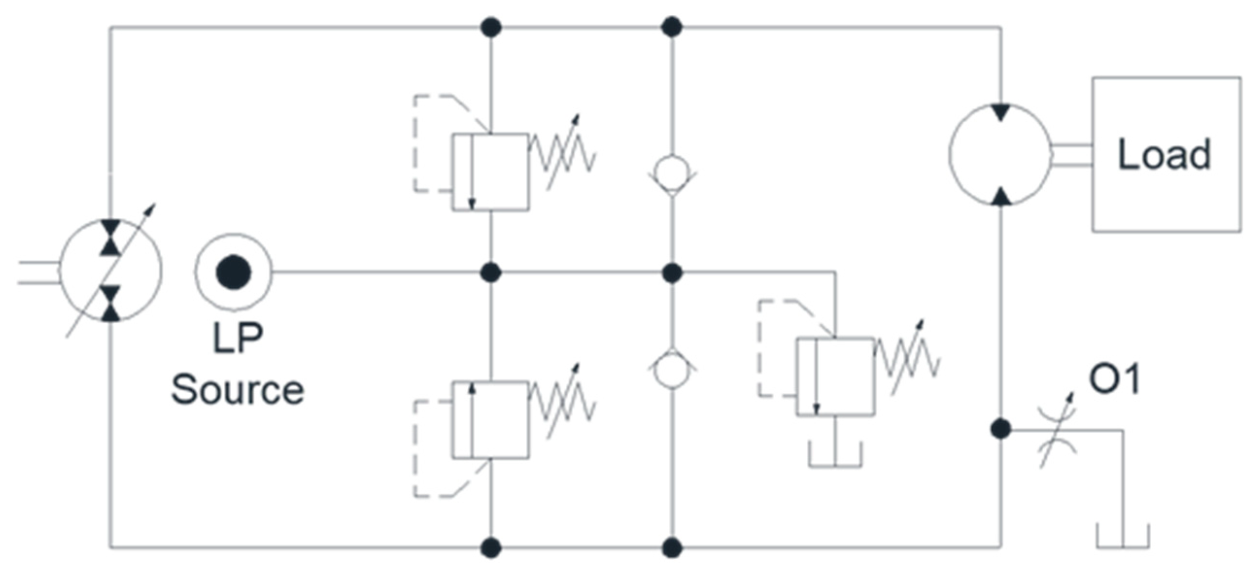
The relationship between the efficiencies of the two systems can be translated into practical operating conditions of a hydrostatic circuit. To illustrate this, a generic hydrostatic transmission was created in Simcenter Amesim®, shown in Figure 6. O1 is a variable orifice to simulate varying demand on the LP system due to volumetric losses and flushing flow. This orifice was simulated between 0% and 100% opening with LP flow provided by either a standard LP supply or an ASPU valve supply. LP flow is supplied by identically-sized pumps, and the relief setting of the standard LP system, p R , is the average of p M I N and p M A X .
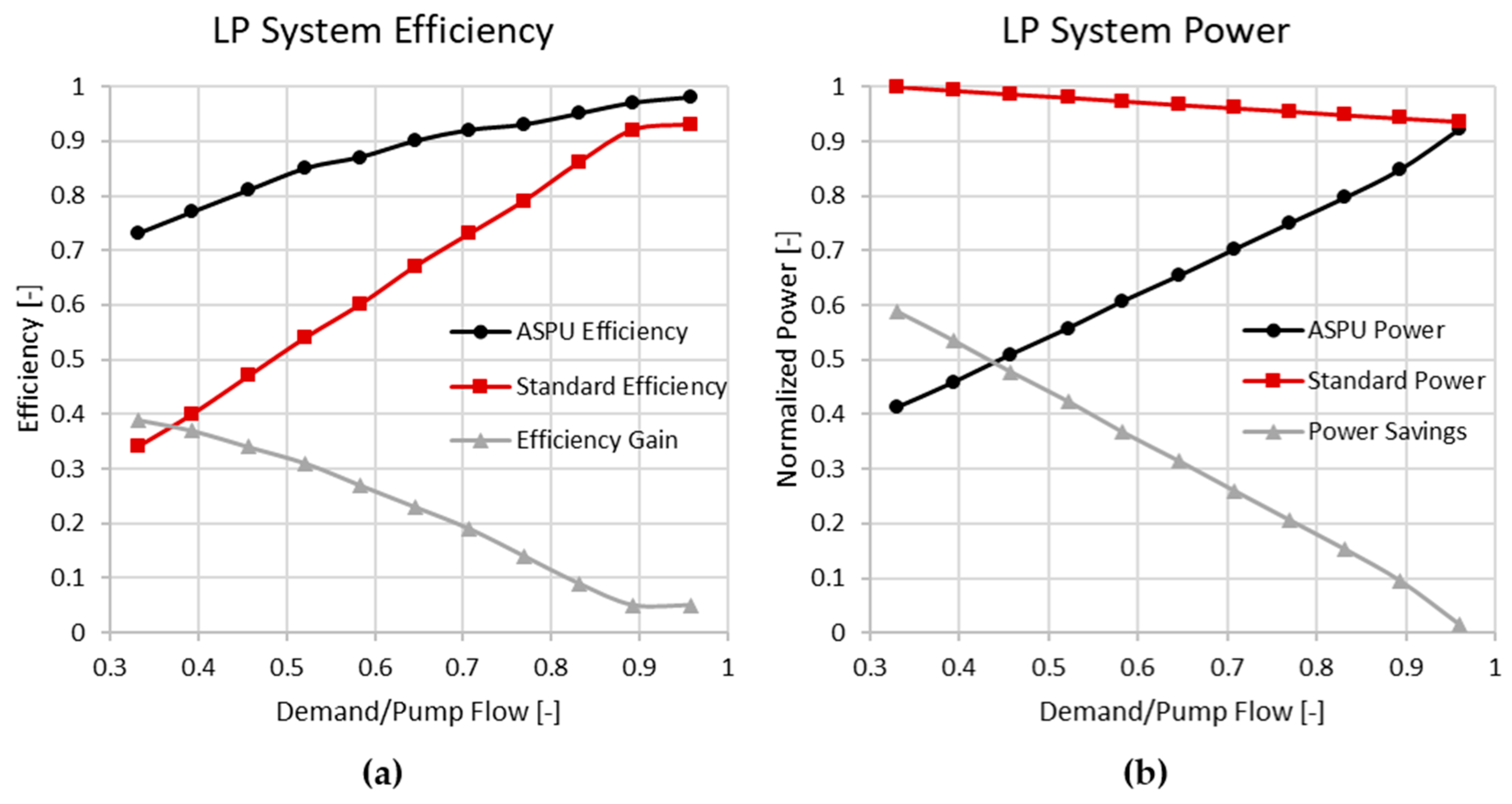
Figure 7 shows the results of this simulation and illustrates the impact of matching charge pump flow, Q C P , with system demand, Q S Y S for both types of LP systems. While flow supplied by each pump is constant, the demand on the LP system is increased as the orifice is opened. As the fraction of flow demanded by the system approaches unity, theoretical hydraulic efficiency of both systems approach unity. These findings echo those shown in Equations (22)–(24). As the efficiency of each system approaches unity, the efficiency difference becomes less pronounced due to more optimal conditions. This dynamic simulation captures trends in energy requirements that were not evident in the mathematical analysis. This is because of the analytical assumption that flow demand is independent of LP pressure. As flow demand is increased, the standard LP system experiences a slight decline in power consumption. This is attributable to more flow leaving the system causing a noticeable decrease in pressure in the LP system. Conversely, the ASPU power consumption is directly proportional to the flow demand, making it suitable for operating over a wide range of conditions.

2.3. Split Low-Pressure Accumulator-Sense Pump-Unloading (ASPU) System

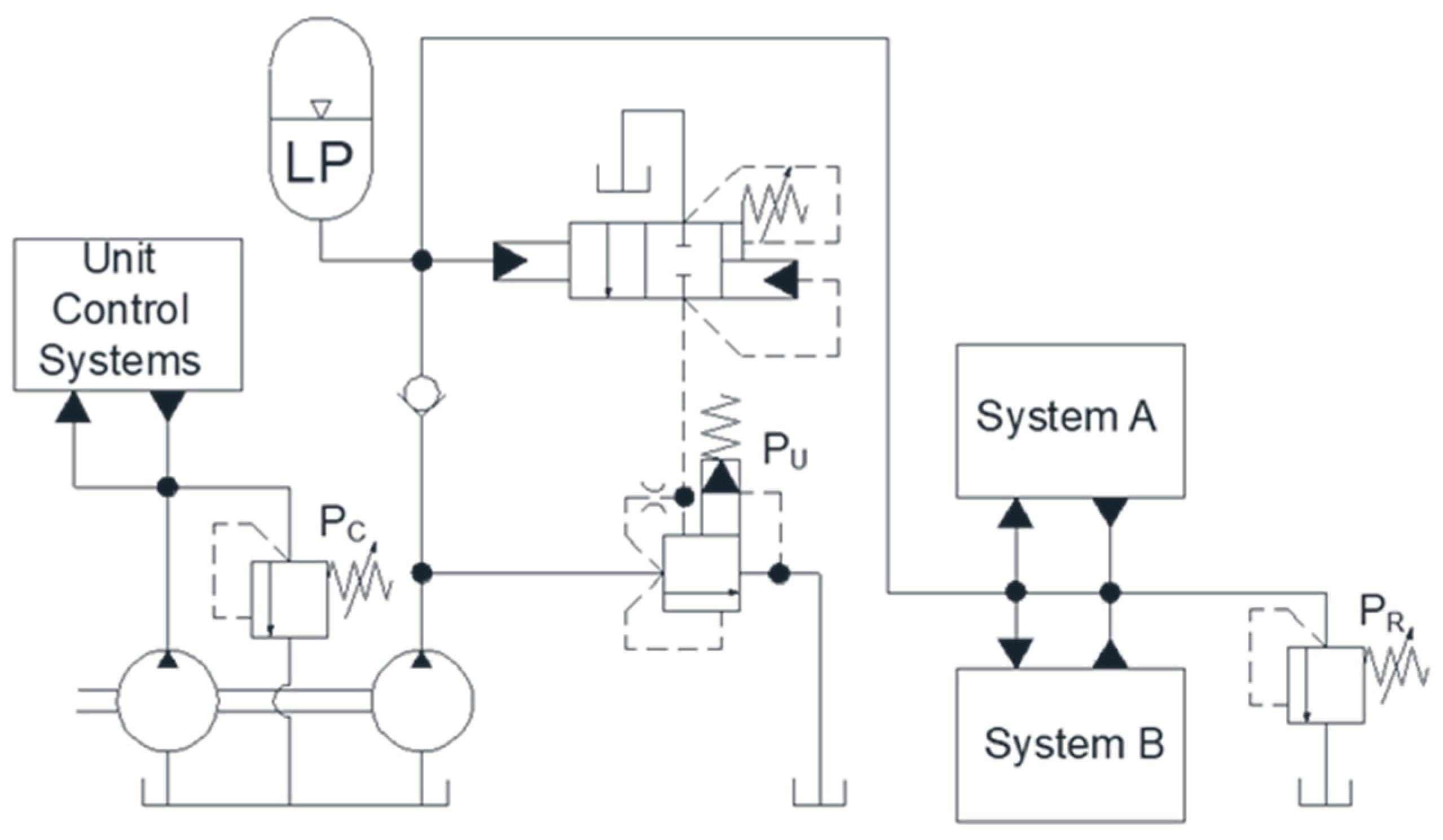
Keller’s proposed split low-pressure architecture achieved a significant power reduction. Further advances in low-pressure architecture can be achieved by the combination of these two technologies. One potential combination is shown in Figure 8. Because many variable-displacement machines allow for external control pressure supply, it is not necessary to provide control pressure by the same circuit which provides flushing and make-up flow. By Equation (1), limiting the flow at the higher control pressure and providing the remaining required flow at reduced pressure will minimize power consumption. Further, unloading unnecessary charge flow at unloading pressure increases the degree of flexibility of the charge system. This is shown in Equation (25):
P = Q C T R L · p C T R L + Q C P ( t ) · p C P ( t )   |   p C P ( t ) = { p L P ( t ) t 1 < t < t 2 p U t 2 < t < t 3

3. Reference System

To demonstrate the potential of adapting this architecture, an investigation is performed on a realistic hydrostatic transmission. Figure 9 shows a complex hydrostatic transmission that incorporates multiple primary and secondary units. System A consists of two independent hydrostatic circuits and System B combines two motors in series. This type of architecture is typical for off-road applications, particularly in agriculture. Unit displacements are outlined in Table 1.
To provide realistic loading behavior, it is assumed that the loading of Units 1 and 2 is provided by fans. To broaden loading variety, Unit 2 is also given variable external loading. Units 3 and 4 are given simply variable external loading. Flushing valves are outfitted on each hydraulic system sized to deliver appropriate flushing flow, a combined 43 L/min, to ensure system cooling. They are sized by determining the equivalent valve area for the desired flushing flow at LP operating pressure. Being a typical circuit consisting of a variety of pump and motor sizes, this transmission will provide realistic, representative results of low-pressure implementation.

3.1. System Modeling

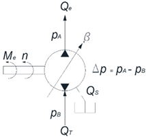
All system components are modeled using a lumped parameter approach in MATLAB/Simulink® using their fundamental driving equations. Components selected for modeling are the following: pumps, motors, hydraulic lines, valves, and implements. A realistic representation of the pumps and motors is the most significant aspect of determining demand on the low-pressure system as this is where most losses are incurred. Table 2 shows the driving equations for system modeling. The relationships between pressure, torque, speed, and flow rate are calculated using the Equations (26)–(29). Losses in the axial piston hydraulic units are provided by high-fidelity empirically derived loss models, interpolated by using a polynomial surface fit of steady-state tests [10,11]. These high-fidelity loss models were unavailable for gerotor-type pumps. Therefore, efficiency data was interpolated from tabulated experimental results [6]. Check valves are characterized according to manufacturer-available data and their flow rates are modeled according to the orifice equation, shown in Equation (30). Relief valves are characterized according to manufacturer-available data and are modeled such that they operate in the linear section of their performance curves, shown in Equation (31). In the special case of the ASPU valve, the cracking pressure of the unloading valve p u was set by a switching condition dependent upon crossing the minimum or maximum accumulator pressure settings. Hydraulic lines are modeled as a single hydraulic capacitance. Their pressure can be calculated by Equation (32). Rotary loads are calculated using a moment balance, Equation (33), and integrating to obtain rotational velocity, Equation (34). For Unit 1, M L O A D ( t ) represents only aerodynamic loading, while for Unit 2, M L O A D ( t ) represents both a dynamic external load and aerodynamic loading. For Units 3 and 4, M L O A D ( t ) represents strictly dynamic external loading. The additional torque provided by aerodynamic loads can be determined by a fan’s coefficients of lift and drag, and C D , and is proportional to the areas of lift and drag, A L and A D , as well as the density of air, ρ, shown in Equation (35). An accumulator is considered additional hydraulic capacitance of a hydraulic line, and is dependent on its total gas volume V G A S , precharge p 0 , instantaneous pressure p A C C U M , and the polytropic coefficient n, shown in Equation (36).

3.2. Representative Duty Cycles

To obtain realistic results, it is necessary to evaluate the performance of the system while operating under conditions that would be typically encountered because low-pressure system requirements are directly correlated with main circuit conditions. Two scenarios typically encountered by this type of system are evaluated for this comparison.
As this low-pressure circuit is expected to be able to respond to varying system demands, a second drive cycle was generated that represented significantly more demanding loading conditions. Average loading conditions were increased, and dynamic loading components were introduced to all units. For Unit 1, speeds were commanded from 1000 RPM to −2000 RPM over a 22 s repeating cycle. A repeatable random number generator L(t) with a mean of 0 and a variance of 50 was introduced to Units 2, 3, and 4 to simulate rough loading conditions. Table 3 and Figure 10 summarize these loading conditions.

4. Results

For baseline results, the reference system was simulated under both static and dynamic operating conditions. Table 4 shows characteristic information for the response of the hydrostatic system to static operating conditions. Differential pressures are provided because they directly correlate with loading conditions. These conditions represent a constant demand on the low-pressure system and can be used as a baseline for comparisons.
Table 5 shows the distribution of flow and power through the reference LP system during static operating conditions. The charge pump provides 97.8 L/min. System A requires 36.8 L/min, of which 20 L/min is flushing flow, and System B requires 28.9 L/min, utilizing 23.4 L/min as flushing flow. This leaves an average of 32.1 L/min of flow over the relief valve. Therefore, of the 5.11 kW of power provided to the charge pump, 1.47 kW of power (29%) is consumed through the relief valve. Neglecting losses in the charge pump, this LP system has an average of 67.2% hydraulic efficiency during the static operating conditions.
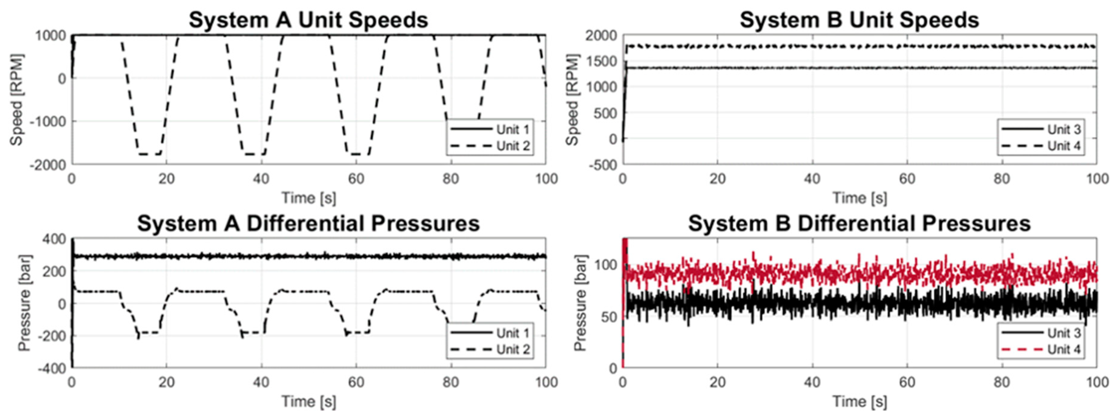
Figure 11 shows the system response to a highly dynamic drive cycle. Unit 1 now operates over a broader range of speeds and pressures. Units 2, 3, and 4 operate at the same speed but are now subject to rapid, unpredictable changes in system pressure. This cycle will test the proposed low-pressure architecture’s ability to respond to dynamic demand.
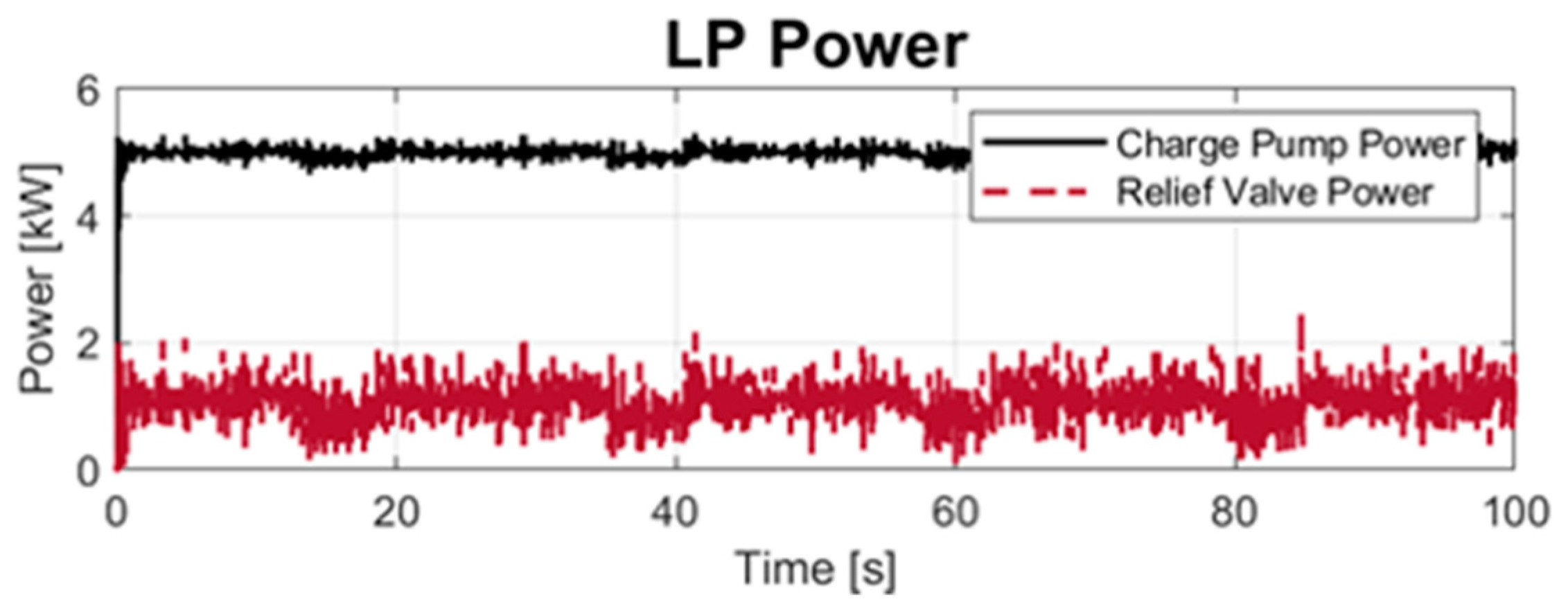
The Dynamic drive cycle highlights the dependency of low-pressure demand on circuit operating conditions. Figure 12 shows the pressure in the LP system along with distribution of flow, while Figure 13 shows power loss over the relief valve compared to charge pump power. The charge pump still supplies the same flow as the static operating condition. However, charge flow demand for System A fluctuate from approximately 31 to 64 L/min with a mean of 41.2 L/min, and System B fluctuates from approximately 32 to 38 L/min with a mean of 3 L/min. Flushing flows for each system are 19.8 and 23.0 L/min, respectively. A mean flow rate of 23.7 L/min is experienced across the LP relief valve, meaning that of the 5.0 kW provided to the charge pump, 1.1 kW (22%) is consumed through the relief valve. The difference in flushing flow is theorized to be due to the difference in mean LP pressures, which are 27.4 and 26.8 bar for average and dynamic drive cycles, respectively. The standard LP circuit exhibits 75.7% hydraulic and 66.2% overall efficiency.
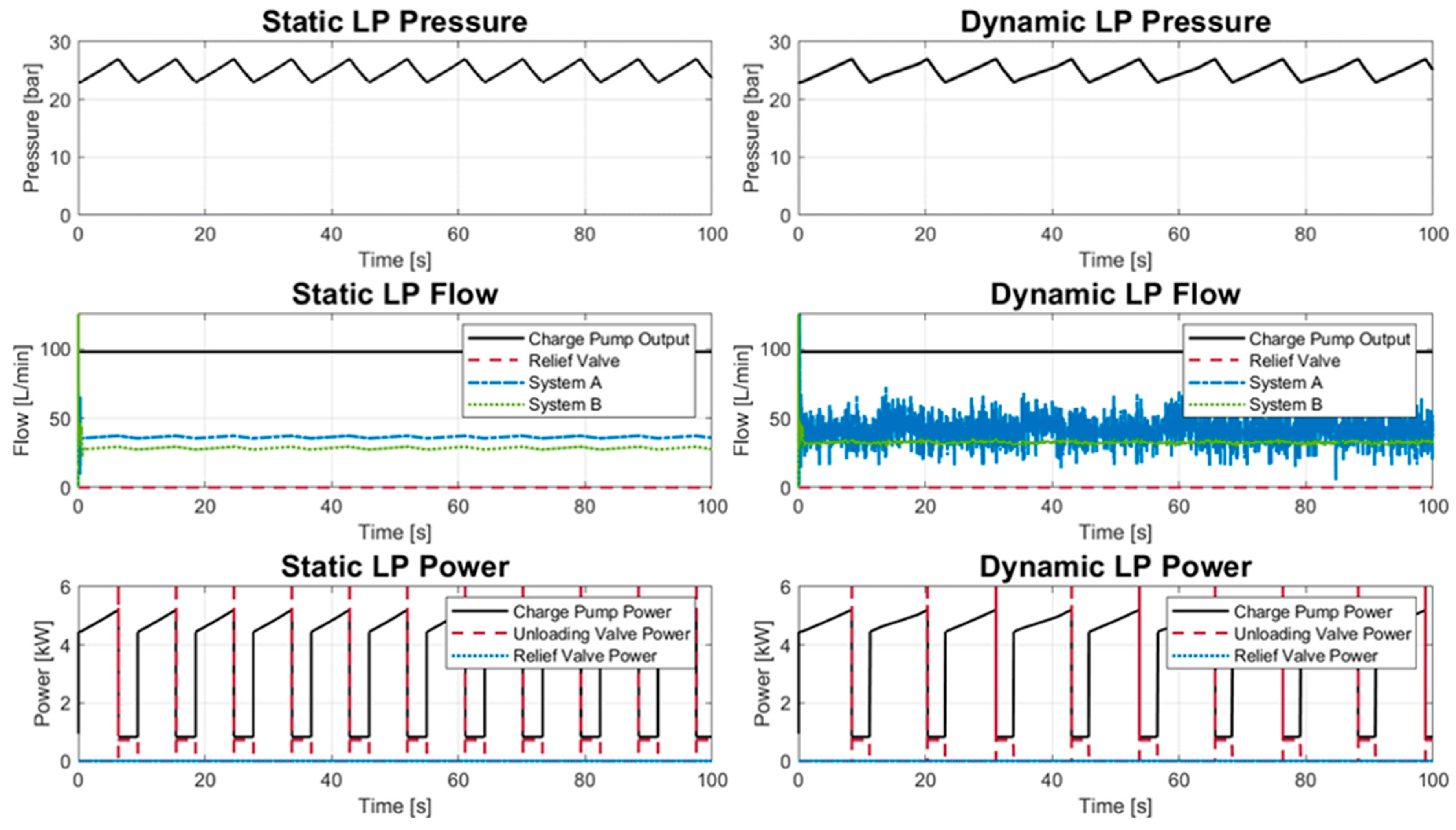
Figure 14 shows the proposed architecture when simulated with identical duty cycles. One key aspect to note are the charge-discharge patterns exhibited by the charge pump power. Power is minimized at full charge due to unloading the pump at low pressure. Most importantly, though, is that relief flow at the LP setting is eliminated. This system maintains the same necessary performance as the reference system with regards to maintaining pressure and flushing flow. However, charge pump now only consumes a mean of 3.49 kW under static operating conditions. During unloading, the valve consumes 0.24 kW to minimize losses. Under these conditions, the proposed system exhibits 92.1% hydraulic and 80.5% overall efficiencies. Under dynamic loading conditions, the charge pump consumes an average 3.88 kW. Instantaneous unloading power consumption is the same, with a mean unloading power of 0.17 kW. Under these conditions, this system exhibits 95.1% hydraulic and 83.0% overall efficiencies. Energy savings of this system are 31.7% and 22.2% for the static and dynamic operating conditions, respectively.
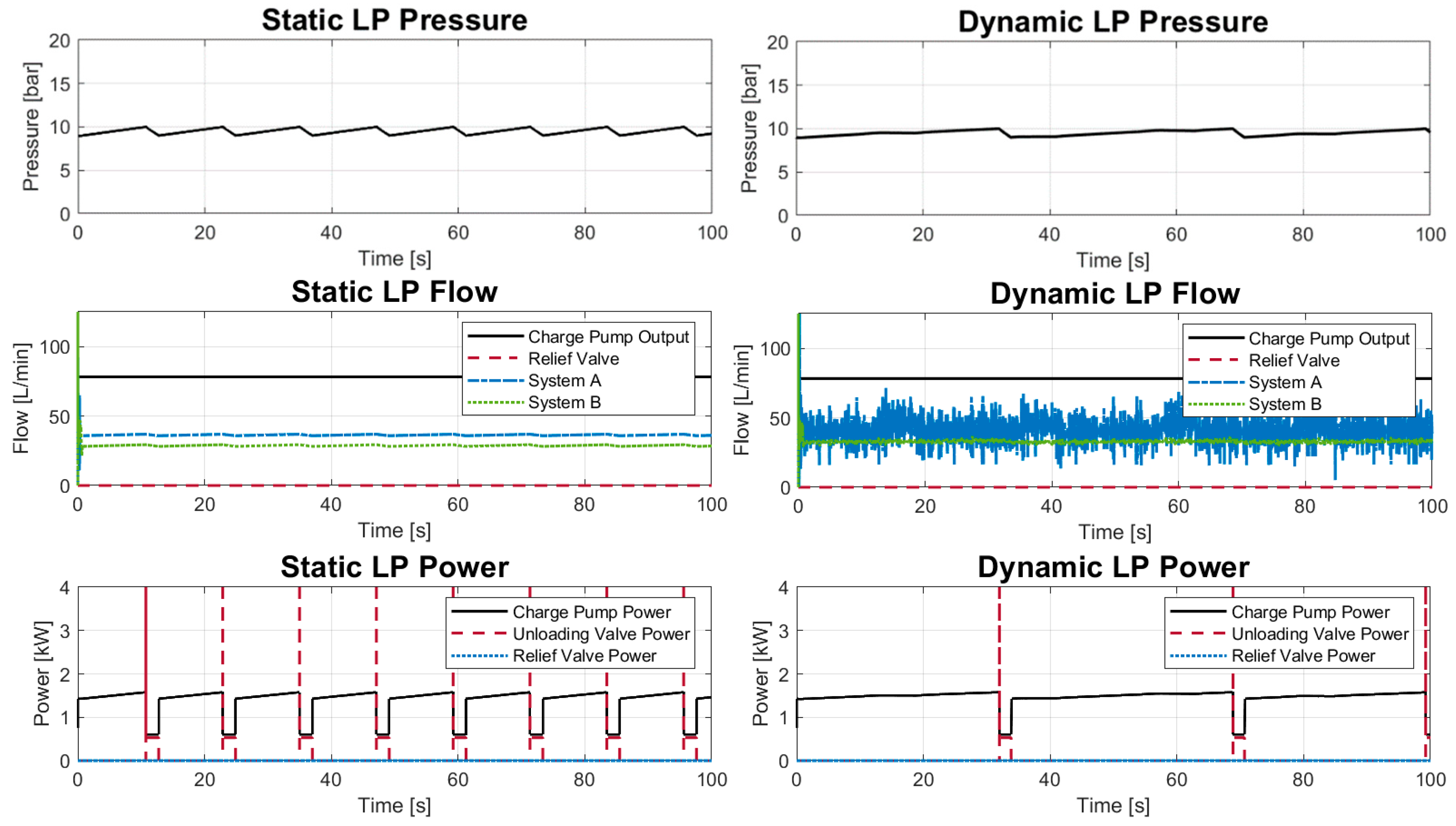
While this valve configuration is readily available, other potential options could improve performance and increase energy savings. For instance, the large margin of operating pressures may be undesirable in many applications where a more stable LP system is necessary for control or other issues. Utilizing a valve with a different area ratio, such as a 10% unloading valve, will produce narrower pressure margins. Another simulation was performed to demonstrate the further energy-saving potentials of a reduced valve ratio in combination with Keller’s split LP architecture, shown in Figure 8. A 10% reset differential was applied to operate in the pressure range of 9–10 bar. Because of the reduced demand on the charge pump, it is also possible to decrease its displacement. A commonly available size, 32cc, was selected for this simulation to illustrate energy-saving potential of a properly sized charge pump. Figure 15 shows the results of this simulation. As the margin of excess pump flow—flow available for accumulator charging—is narrower, the operating condition’s impact on the LP system is magnified.
The charge pump is still capable of providing the demanded flow to the circuits while maintaining a minimum pressure to ensure no cavitation will occur. The pump consumes a mean of 1.4 kW and 1.5 kW for the Static and Dynamic drive cycles. The efficiencies under static loading conditions are 92.8% hydraulic and 81.1% overall. The efficiencies under dynamic loading conditions are 98.1% hydraulic and 85.1% overall. Accounting for the tertiary pump consuming 0.4 kW, this represents savings over the reference LP system of 3.3 kW (65%) and 3.0 kW (60%), respectively.
Figure 16 shows a comparison of the three systems across both drive cycles. This plot accounts for the 0.5 kW required to maintain 10 L/min of flow at 25 bar for unit displacement control systems. Both proposed systems exhibit significantly lower power consumption than the reference systems under both operating conditions due to minimization of constant power loss. These results are summarized in Table 6.

5. Conclusions

Standard low-pressure circuits have been shown to be a significant consumer of power in hydraulic systems, requiring up to 5.1 kW on the reference system. To minimize total power losses in hydraulic systems, this was addressed by the application of an accumulator-sense pump-unloading valve to direct charge flow. By analysis, it was shown that power consumption can be reduced by setting unloading pressure to a minimal value, matching the charge flow closely with the flow required by the system, and optimizing the working pressure ranges of the accumulator. Through dynamic, lumped parameter simulations, it has been demonstrated that integrating an ASPU valve LP system into a typical multi-function, mobile hydraulic circuit, presents significant power savings. By this alone, a power savings of up to 31.7% was demonstrated with an increase in hydraulic efficiency of up to 37.1% over the reference system. Further, it was shown that coupling the split-LP system architecture proposed by Keller with an ASPU is a synergistic method of further reducing parasitic LP power losses while providing adequate make-up and cooling flow. Through proper sizing of the charge pump and correct implementation of precise ASPU valves, energy savings of up to 64.5% are possible during average loading conditions while improving LP flexibility due to accumulator storage. To maintain hydraulic architecture relevance in a world of electrification, modern solutions are essential to maximize system efficiency. It is shown that significant energy savings are possible by creative application of hydraulic controls to low-pressure circuits.

Author Contributions

Conceptualization, P.M.S. and N.K.; Data curation, P.M.S.; Formal analysis, P.M.S.; Funding acquisition, A.V.; Investigation, P.M.S.; Methodology, N.K.; Project administration, A.V.; Resources, A.V.; Software, P.M.S.; Supervision, A.V.; Validation, P.M.S.; Visualization, P.M.S.; Writing—original draft, P.M.S.; Writing—review and editing, N.K.

Funding

This research received no external funding.

Acknowledgments

The authors graciously acknowledge Xiaofan Guo for his assistance in developing the analytical equations. The authors also thank Maha Fluid Power Research Center and Purdue University for graduate assistantship funding which made this research possible.

Conflicts of Interest

The authors declare no conflict of interest.

References

  1. Lynch, L.; Zigler, B.T. Estimating Energy Consumption of Mobile Fluid Power in the United States; NREL/TP-5400-70240; National Renewable Energy Lab. (NREL): Golden, CO, USA, 2017. [Google Scholar] [CrossRef]
  2. Keller, N.J. A 21st Century Approach to Hydraulic Actuation Technology; Purdue University: West Lafayette, IN, USA, 2017. [Google Scholar]
  3. Dengler, P.; Geimer, M.; Baum, H.; Schuster, G.; Wessing, C. Efficiency Improvement of a Constant Pressure System Using an Intermediate Pressure Line. In Proceedings of the 8th International Fluid Power Conference, Dresden, Germany, 26–28 March 2012; Volume 1, pp. 567–578. [Google Scholar]
  4. Dreher, T. The Capability of Hydraulic Constant Pressure Systems with a Focus on Mobile Machines; Ivantysynova, M., Klop, R., Eds.; FPNI Fluid Power Net Publications: Modena, Italy, 2010; pp. 579–588. [Google Scholar]
  5. Vukovic, D.I.M.; Leifeld, M.S.R.; Murrenhoff, I.H. STEAM- A Hybrid Hydraulic Architecture for Excavators. In Proceedings of the 10th International Fluid Power Colloquium, Dresden, Germany, 8–10 March 2016; Technical University Dresden: Dresden, Germany, 2016; Volume 3, pp. 151–162. [Google Scholar]
  6. Cundiff, J.S. Fluid Power Circuits and Controls: Fundamentals and Applications; Mechanical Engineering Series; CRC Press: Boca Raton, FL, USA, 2002. [Google Scholar]
  7. Zavadinka, P.; Grepl, R. Energy Saving Potential of a Hydrostatic Drivetrain with Variable Charge Pump. In Proceedings of the 8th FPNI Ph.D. Symposium on Fluid Power, Lappeenranta, Finland, 11–13 June 2014; American Society of Mechanical Engineers: Lappeenranta, Finland, 2014; p. V001T02A009. [Google Scholar] [CrossRef]
  8. Keller, N.; Ivantysynova, M. A New Approach to Sizing Low Pressure Systems. In Proceedings of the ASME/BATH 2017 Symposium on Fluid Power and Motion Control, Sarasota, FL, USA, 16–19 October 2017; American Society of Mechanical Engineers: Sarasota, FL, USA, 2017; p. V001T01A071. [Google Scholar] [CrossRef]
  9. Nervegna, N. Oleodinamica e Pneumatica, Febbraio 2003; Sistemi; Politecnico di Tornino: Turin, Italy, 2003; Volume 1. [Google Scholar]
  10. Zimmerman, J.D. Toward Optimal Multi-Actuator Displacement Controlled Mobile Hydraulic Systems. Ph.D. Thesis, Purdue University, West Lafayette, Indiana, 2012. [Google Scholar]
  11. Mikeska, D.; Ivantysynova, M. A Precise Steady-State Model of Displacement Machines for the Application in Virtual Prototyping of Power-Split Drives. In Proceedings of the 2nd International FPNI-PhD Symposium on Fluid Power, Modena, Italy, 3–6 July 2002; FPNI Fluid Power Net Publications: Modena, Italy, 2002; pp. 3–6. [Google Scholar]
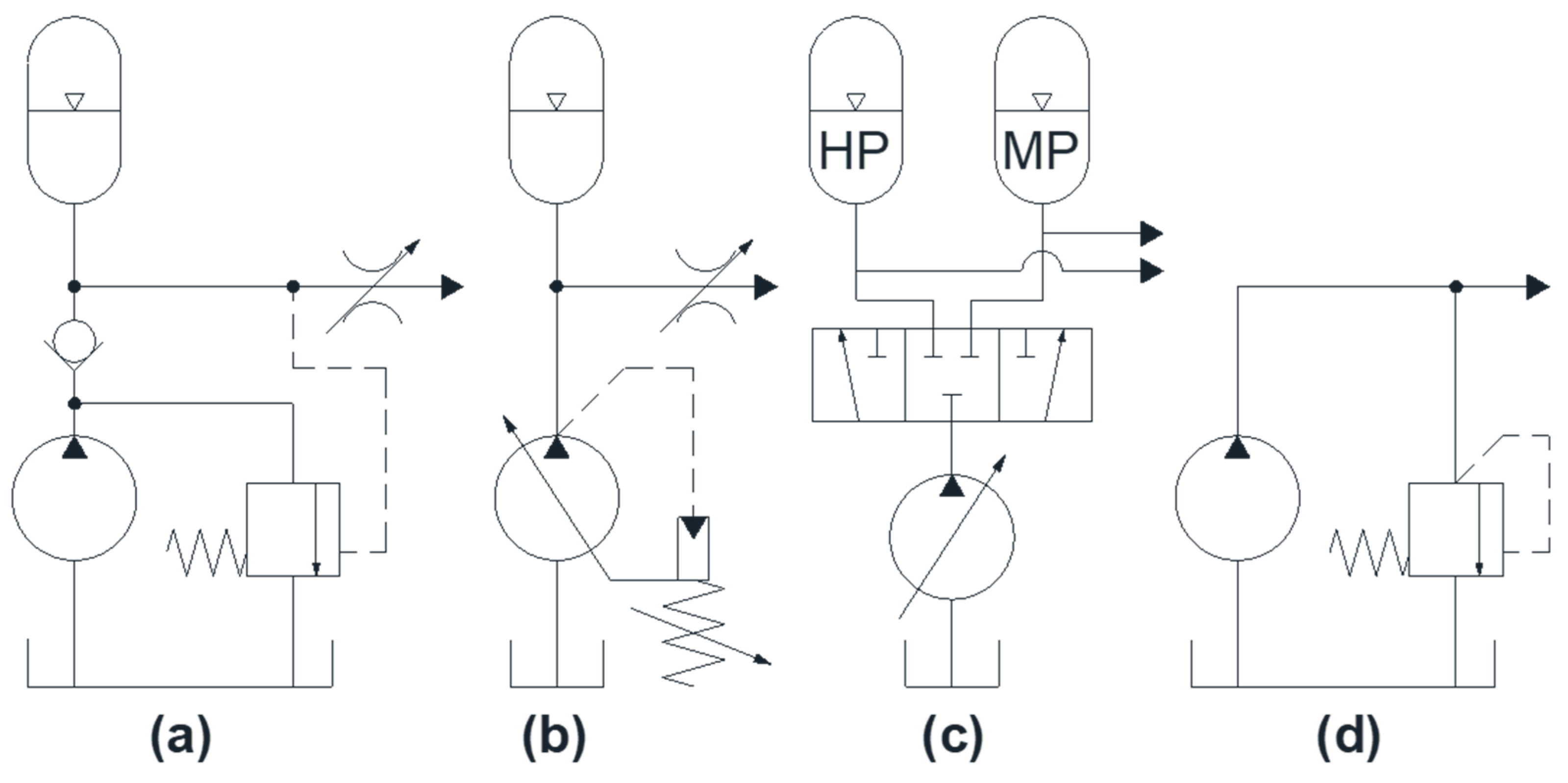
Figure 1. Four possible constant pressure systems: (a) Fixed displacement pump with accumulator, (b) Pressure compensated pump with accumulator, (c) Multiple pressure rail system, and (d) Fixed displacement pump at constant relief pressure.
Energies 12 04423 g001
Figure 2. (a) Accumulator-sense pump-unloading (ASPU) valve, (b) duty cycle representation.
Energies 12 04423 g002
Figure 3. (a) Proposed low-pressure (LP) architecture with ASPU valve, (b) Reference system.
Energies 12 04423 g003
Figure 4. LP hydraulic power consumption.
Energies 12 04423 g004
Figure 5. Efficiency comparison of ASPU and standard LP systems.
Energies 12 04423 g005
Figure 6. Generic hydrostatic transmission for efficiency comparison.
Energies 12 04423 g006
Figure 7. (a) Hydraulic efficiency and (b) power consumption versus fraction of demanded flow.
Energies 12 04423 g007
Figure 8. Proposed split LP system with ASPU valve.
Energies 12 04423 g008
Figure 9. Reference system hydraulic schematic.
Energies 12 04423 g009
Figure 10. Dynamic operating condition simulation inputs.
Energies 12 04423 g010
Figure 11. Reference system response to dynamic operating conditions.
Energies 12 04423 g011
Figure 12. Low-pressure results of dynamic simulation.
Energies 12 04423 g012
Figure 13. Low-pressure power consumption.
Energies 12 04423 g013
Figure 14. Proposed ASPU LP system results of both static and dynamic operating conditions.
Energies 12 04423 g014
Figure 15. 10% ASPU valve with split LP system results for static and dynamic operating conditions.
Energies 12 04423 g015
Figure 16. Power consumption of three evaluated systems accounting for tertiary control pump.
Energies 12 04423 g016
Table 1. Reference system pump and motor displacements.
Pump Size (cc)Motor Size (cc)
System A55
55
100
75
System B55100
75
LP System40N/A
Table 2. System modeling equations.
Pumps/Motors
Energies 12 04423 i001 Q T = β n V i (26)
M T = Δ p V i 2 π (27)
Q e = Q t ± Q s (28)
M e = ± M t M s (29)
Check Valves
Energies 12 04423 i002 Q c v = { C v C 2   ( p L P p L i n e ) ρ i f   p L P > p L i n e                 0                 i f   p L P p L i n e   (30)
Relief Valves
Energies 12 04423 i003 Q R = { C v R ( p A p B ) i f   p A > p S e t             0             i f   p A p S e t   (31)
Hydraulic Lines
Energies 12 04423 i004 p L i n e = 1 C H   ( Q p u m p , e Q m o t o r , e + Q c v Q r e l i e f ) d t (32)
Rotary Load
Energies 12 04423 i005 M e = I ω ˙ + M L o a d ( t ) (33)
ω ( t ) =   ω ˙ ( t ) d t (34)
Fan Load
Energies 12 04423 i006 M L o a d ( t ) = 1 2 ρ   C d   A D ω 2 + 1 2 ρ   C L   A L ω 2 (35)
Accumulator
Energies 12 04423 i007 C H , A c c u m = V G A S n · ( ( p 0 p A C C U M ) 1 + n ) 1 n (36)
Table 3. Inputs to simulation.
Static Operating ConditionDynamic Operating Condition
SpeedLoadSpeedLoad
Unit 11000 RPMN/A−2000–1000 RPMN/A
Unit 21000 RPM250 Nm1000 RPM350 + L(t) Nm
Unit 3β = 100%40 Nmβ = 100%80 + L(t) Nm
Unit 445 Nm90 + L(t) Nm
Table 4. System response to static operating conditions.
Average Speed (RPM)Average Differential Pressure (bar)
Unit 1998.6222.6
Unit 21000.072.0
Unit 31387.237.0
Unit 41827.951.1
Table 5. Low-pressure results of a standard system for static conditions.
Charge PumpSystem ASystem BRelief Valve
Flow (L/min)97.836.828.932.1
Power (kW)5.11 (mechanical)1.921.511.47
Pressure (bar)27.4 bar
Efficiency (%)67.2 hydraulic, 58.7 overall
Table 6. Summary of power consumption and savings.
SystemStatic Operating ConditionsDynamic Operating Conditions
Mechanical Power (kW)Savings (%)Hydraulic Efficiency (%)Mechanical Power (kW)Savings (%)Hydraulic Efficiency (%)
Reference 5.11N/A67.24.99N/A75.7
15% ASPU Valve3.4931.792.13.8822.295.0
10% ASPU Valve
With Split LP
1.8264.592.81.9362.298.1