Article

Development and Numerical Performance Analysis of a Pump Directly Driven by a Hydrokinetic Turbine

1
College of Energy and Electrical Engineering, Hohai University, Nanjing 211100, China
2
College of Agricultural Engineering, Hohai University, Nanjing 210098, China
3
College of Water Conservancy and Hydropower Engineering, Hohai University, Nanjing 210098, China
*
Author to whom correspondence should be addressed.
Energies 2019, 12(22), 4264; https://doi.org/10.3390/en12224264
Submission received: 23 September 2019 / Revised: 4 November 2019 / Accepted: 7 November 2019 / Published: 8 November 2019
(This article belongs to the Section A: Sustainable Energy)

Abstract

:
Marine and hydrokinetics (MHK) represent an emerging industry with hundreds of potentially viable technologies, such as potential extractable energy from plain area rivers where the water level differences are very small and the traditional water turbine pump (WTP) cannot be used. A suitable WTP, composed of a tubular turbine directly driving a centrifugal pump, was designed and developed based on computational fluid dynamics (CFD) and model tests. Two general design schemes of such river-current (RC)-driven WTP are presented here, obtaining the desired operating parameters of discharge and pump head. A CFD analysis of Scheme B, which employs a radial outlet, allowing additional degrees of freedom for the dimensions of the centrifugal pump, was carried out and verified experimentally by model tests. The minimum deviation of pump head is within ±5%, and the trend of other working conditions is consistent, so the results of the numerical simulation and model tests show good agreement, demonstrating the feasibility of the CFD method for practical applications. Then, using the CFD method, the optimum rotational speed for the turbine was determined, and the turbine draft tube was improved further. With a turbine runner diameter of 0.5 m, the results show best performance at n = 350 r/min. The straight conical draft tube was changed to an elbow draft tube with multiple exits. Additionally, four different cross-sectional shapes were designed for the pump volute, and their effects on the performance of the WTP were analyzed. Finally, the round shape was selected, because of its best performance. The turbine unit has the highest efficiency of 81.2%, at an inlet velocity v = 2.4 m/s, while the pump exhibits the best efficiency of 90.2% at the design discharge and head of 30 l/s and 4.45 m respectively. Overall, the RC-driven WTP makes good use of the kinetic energy of the river current as a power source, solving the inapplicability of traditional WTP in plain areas.

Graphical Abstract

1. Introduction

With the aggravation of the traditional energy crisis and the increasingly prominent environmental problems, people turn their attention to the inexhaustible renewable energy, hoping to change the energy structure of human beings and achieve sustainable development [1,2]. Renewables are responsible for almost 45% of the world’s increase in electricity generation in 2018, and they now account for 25% of the world’s power demand [3]. By technology, hydropower covers about 85% of the renewable energy power generation for its affordable, renewable, and flexible superiority [4]. Compared to other of renewable energy forms, there is far less experience with harnessing the marine and hydrokinetics (MHK) resource, but MHK technologies have been proven to produce electricity reliably in both the field and laboratory [5]. MHK energy technologies convert the energy of waves and tides, as well as river and ocean currents, into environmentally sustainable and cost-effective electricity [6,7]. Unlike hydropower, MHK represent an emerging industry with hundreds of potentially viable technologies. Among them, the development and utilization of no head run-of-river schemes which always takes place in some plain areas, is also an important part of MHK technologies.
The water turbine pump (WTP) [8] is a kind of hydraulic machinery that is composed of a water turbine and a pump linked together, directly or indirectly, which combines the whole process of generating renewable energy from water resources and utilizing the generated energy for water pumping [9,10]. The basic principle of the river-current (RC)-driven WTP consists of the usage of water kinetic energy to drive a turbine, which in turn drives a pump that pumps water from the flowing body of water. This therefore means that the flowing water can be pumped from a low to higher altitude, thus transforming its kinetic energy into potential energy, and, in the particular case here, the relatively low specific kinetic energy of the water body with large flow discharge and low head is turned into the energy of a small flow discharge with high lift [11]. This direct method of pumping water eliminates the need for hydroelectric power or other means of electricity generation and the loss of electric energy in the process of a number of intermediate energy conversion links. Furthermore, with a reasonable WTP design, the energy utilization can be even higher than with other forms of water-lifting machinery [12]. At the same time, it also saves a considerable amount of mechanical and electrical equipment installation, and the corresponding infrastructure cost [13].
With the expansion and development of the concept of WTP, it has been applied in different fields, such as desalination process, fire protection, and pumped hydropower station. In the desalination system, adding a WTP device to recover energy can achieve a significant energy-saving effect, which can cut energy consumption by 70% and water treatment cost by 40% [14,15,16]. A WTP can be convenient to connect to piping and can be directly started without water priming. Also, the unit can be small, lightweight, portable, and easy to operate. Thus, the RC-driven WTP has been used to make untreated water available for emergency situations, such as fire. The fire WTP solves the problem of fire-water supply, and shortens the starting time of fire-protecting operations [17]. In locations unsuitable for hydro power plants, WTP can convert an unstable and inconvenient water supply into a stable water supply, which can be powered independently, with flexibility and adaptability, on demand, at any time [18]. WTP power station can be used in mountainous areas, rivers and coastal areas, especially on islands with electricity shortage.
Since the beginning of the 21st century, there has been only little research on WTP design, and the literature before 2000 happens to be mainly theoretical research and design selection. Because the traditional WTP requires a considerable water head, and it is typically unable to utilize only the kinetic energy of a river flow, the promotion of WTP has been greatly hampered in plain areas. However, in many rivers, streams, and ditches with flat terrain, due to the influence of natural terrain, it is unable to provide a more appropriate water flow drop, so the power equipment of the WTP cannot give full play to its advantages. Therefore, it has become an urgent need to develop a kind of equipment that can start the operation of the WTP only by water velocity.
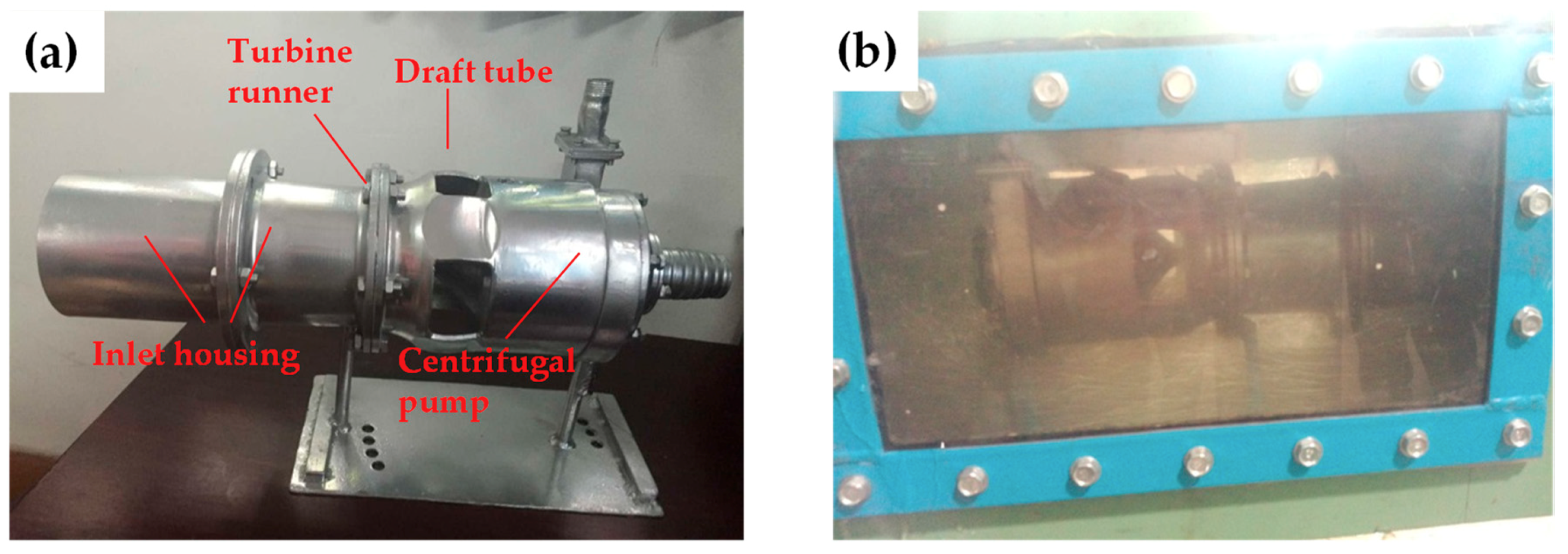
This paper focuses on developing a simple structure and high-efficiency design scheme for RC-driven WTP which is suitable for rivers or channels where a hydrokinetic turbine can be placed in a plain area. The design objective is an inlet velocity at least 1.5 m/s for the hydrokinetic turbine and 30 l/s flow rate and at least 4.0 m lift for the low specific speed centrifugal pump, with an efficiency of best more than 70.0% and 80.0%, respectively, for turbine and pump, so that the water kinetic energy in a plain area or coastal area can be exploited fully. The work started with a preliminary design of the RC-driven turbine, centrifugal pump, and the shape of the flow passages. Then, a model test was carried out to verify the reliability of the numerical simulation method. Finally, CFD numerical simulation method was used to further improve the design of the turbine draft tube and the pump volute.

2. Research Method

2.1. Initial Model Design

The development and design goal of the WTP is to obtain a best efficiency of more than 70% and 80% for the turbine and pump, respectively, while meeting the requirements of low start-up flow velocity of 1.5 m/s, high head >4 m, at 30 l/s flow rate, simple structure, compact design, and portability, potentially at a low cost. To be able to utilize the kinetic energy of the flowing river water in plain areas or coastal areas, a low head hydrokinetic axial turbine was chosen and combined with a low specific speed centrifugal pump to obtain the required head and flow rate [19]. Since the WTP is immersed in the river flow, the centrifugal pump is filled with water (primed) at the moment it is deployed in the river.
The major parts of the hydrokinetic WTP are the turbine inlet, support, turbine runner, draft tube, hub cover, shaft, pump inlet, pump impeller, and volute. The shaft is arranged in horizontal axis. In general, two schemes of integrating the pump with the turbine on one shaft were considered (Figure 1). In both, the centrifugal pump has an opposite flow direction to the turbine. In Scheme A, the centrifugal pump is arranged in a bulb body inside the straight conical draft tube of the turbine with axial outlet, so that the outflow of the turbine in the draft tube bypasses the pump within the unit. Scheme B [19] has a multiple radial outlet elbow-shaped draft tube, and the centrifugal pump is flanged on from the downstream side, so that the outflow from the turbine bypasses the pump externally of the unit. This has allowed the turbine and the centrifugal pump to share the same unit diameter, increasing the size of the centrifugal pump 1.5 times compared to the considered example of Scheme A.
The hydrokinetic WTP features a conical inlet for pump and turbine and a hub cover to reduce flow losses. The blade number of hydrokinetic turbine and pump is 5 and 6, respectively. The turbine runner blades have a high span-to-cord aspect ratio, to reduce the flow resistance of the runner [20], and the airfoil chord angle of blade tip and root relative to the axis were 15° and 33°, respectively. Therefore, the blades have strong overall flow capacity, as well as great advantage for self-startup ability over the traditional turbine blades [21]. The pump blades are simple constant thickness blades with a round leading edge and a wrap angle of 120°. Furthermore, the diameter of the turbine runner is 0.5 m, and the pump impeller diameter of the Scheme A and B are 0.35 m and 0.5 m, respectively.

2.2. Model RC-Driven WTP Test

The model test was implemented on a multifunction hydro-mechanical experimental test rig at Hohai University. In the conventional model hydraulic turbine or pump test, the systematic error of the test bed is relatively certain value 0.265%, which is obtained by referring to Reference [22]. However, the random error of different test devices varies between 0.2% and 0.3%, so the total error is between 0.33% and 0.4%. The experimental test rig and equipment are shown in Reference [23]. The model used in the test was manufactured according to Scheme B, and its diameter is 0.1 m because of the limitation of test bench size (Figure 2a). The physical model is fixed in the rectangular section pipe of 0.4 m × 0.36 m through bolt (Figure 2b). The centrifugal pump outlet is connected to a pipe which is linked to the pipeline outside, and then a three-way valve is attached. One outlet of the three-way value is combined with a digital display pressure meter which is used for measuring water lift and has an accuracy of ±0.075%. Another outlet is bonded with a rubber hose, and a cylinder is placed on the ground to measure the pump’s flow rate by volumetric approach, and the measurement uncertainty of the measuring cylinder is less than ±0.3%. Additionally, the discharge flow through the pump can be changed by opening of the three-way value. The average flow velocity in the rectangular section pipe is adjusted by changing rotational speed of the variable speed circulating pump, and an intelligent frequency meter with an accuracy of 0.5% full scale is applied to measure model rotational speed. Figure 3 provides the model WTP installation diagram of the test loop.
After the test piping system is filled with water, the variable speed circulating pump is started, to make the water circulate in the piping system for a period of time. When the flow velocity in the rectangular section pipe reaches a certain value, WTP starts to rotate. Then, the rotating speed of the circulating pump is adjusted to make the reading of the electromagnetic-flow meter reach the required value, so as to ensure the average velocity inside the rectangular section pipe reaches 2 m/s. While the velocity remains unchanged, the operation point of the pump can be changed by adjusting the opening degree of the water outlet valve in the WTP.

2.3. Solution Algorithm

The commercial software ANSYS Fluent 16.0 software (Ansys2016, ANSYS, Canonsburg, PA, USA) was used for current three-dimensional turbulent quasi-steady calculation. Considering that the water is incompressible viscous fluid, the continuity equation and the quasi-steady-state Reynolds-averaged Navier–Stokes equation for an incompressible flow were used in the following form [24,25]:
u i x i = 0
ρ u j x j ( u i ) = ρ F i p x i + μ 2 u i x j x j
where u is the velocity, xi and xj are the Cartesian coordinate components, i and j can make values of 1,2, and 3 in order to take three dimensions into account, ρ is the density of fluid, Fi is the body force per unit volume, p is the pressure, and µ is viscosity.
The finite volume method was adopted to disperse the controlling system of equations [26]. The Spalart–Allmaras (S–A) model was chosen because of its high convergence rate and low mesh-quality requirements [27,28]. The S–A model has been widely applied in hydraulic machinery design because it can predict the power characteristics better and has high computational efficiency. Moreover, it can work well with complex boundary problems, because of a single transportation equation with a small amount of calculation, especially fitting for external field flow problem and boundary layer flow with an adverse pressure gradient [29,30]. In this model, the turbulent working variable, v ^ , was introduced to define the turbulent viscosity as follows [31]:
v t = v ^ f v 1 ,   f v 1 = χ 3 χ 3 + C v 1 ,   χ = v ^ v ,
where f v 1 is the viscous damping function, and v is the molecular kinematic viscosity.
The transport equation for v ^ is as follows:
v ^ t + ( v ^ u i ) x i = 1 σ { · [ ( v + ( 1 + C b 2 ) v ^ ) v ^ ] C b 2 v ^ Δ v ^ } + Q
where σ and C b 2 are constant, and Q is the source term, which can be described as follows:
{ Q = C b 1 S ˜ v ^ C w 1 f u ( v ^ d ) 2 ;   S ˜ = S f v 3 + v ^ κ 2 d 2 f v 2 ; f v 2 = 1 ( 1 + χ / C v 2 ) 3 ;   f v 3 = ( 1 + χ f v 1 ) ( 1 f v 2 ) χ f w = g ( 1 + C w 3 6 g 6 + C w 3 6 ) 1 6 ;   g = r + C w 2 ( r 6 r ) ; r = v ^ S ˜ κ 2 d 2 ;
where d is the distance from the wall, and S is a scalar measure of the deformation tensor. The model constants C b 1 , C b 2 , σ , C v 1 , C v 2 , C w 1 , C w 2 , C w 3 , and κ have the following default values: C b 1 = 0.1355, C b 2 = 0.622, σ = 2 3 , C v 1 = 7.1, C v 2 = 5, C w 1 = C b 1 κ 2 + 1 + C b 2 σ , C w 2 = 0.3, C w 3 = 2, and κ = 0.41.
To ensure the calculation precision, the second-order central-difference scheme was applied for the calculation of the pressure term; the second-order upwind scheme was employed for the implicit solution of the momentum term, turbulent dissipation rate, and turbulent kinetic energy. Also, SIMPLEC method was adopted for the pressure–velocity coupling, and residual error 10−5 was used as the criterion of convergence in the calculation.

2.4. Grid and Boundary Conditions

The CFD calculation domain included six parts: the water turbine inlet passage, the runner, the draft tube, the centrifugal pump inlet channel, the pump impeller, and the volute. Grid partition method was adopted for grid generating, and the interface was defined to connect each area. With multiple reference frames applied [32,33], the flow in turbine runner and pump impeller were computed in a rotating frame, while the rest were set in stationary frame. Due to the complexity of the turbine runner and pump impeller, face mesh was first encrypted for turbine blades and the pump blades, and then the fluid in each region was directly divided in a volume grid. Considering the irregular changes of the computational area and the grid quality, the unstructured mesh was generated throughout the whole hydrokinetic WTP model [31]. The unstructured mesh was used because of its advantage of fast-generated speed and good adaptability for most complex structure.
In general, the more the mesh numbers, the higher accuracy of numerical simulations, but a larger grid number means a greater amount of calculation and longer computation time, and this will cause a big rounding error of floating-point operation, as well as the reduction of calculation precision, so it is necessary to verify the grid independence of the computational flow field. In order to capture the characteristics of the near-wall flow, 10 layers of the grids were defined in boundary layer around the blade-wall boundaries, to reduce y+ near the wall region, and when the distance of the first mesh layer to the wall was 0.002 m, finally the y+ range was 5~60, since the main concern of the research is the blade torque. Meanwhile, a local mesh-refinement method was adopted to the runner, and a structured tetrahedral grid was used in the boundary layer. Theoretically, the flow fields of turbine and pump do not interfere with each other, so mesh independence was checked by using five different mesh systems for turbine and pump, respectively (Figure 4). For the turbine and pump, when the mesh number exceeded 2.7 million and 1.15 million, respectively, the performance parameters basically remained unchanged, and the precision is accurate enough for the present purpose, so a mesh system with more than 3.85 million cells was sufficient for this study.
Velocity inlet was chosen as inlet and pressure-outlet was applied to outlet for turbine. Mass flow rate was chosen as inlet and outflow was applied to outlet for pump. No-slip boundary condition was adopted to the solid walls, and standard wall functions for the near-wall region [34].

2.5. Experimental Validation

Through the RC-driven WTP model test when (turbine inlet velocity) v = 2 m/s and (rotating speed) n = 381.97 r/min, the hydraulic performance curves of model centrifugal pump were obtained. The results were converted into prototype experimental data according to similarity theorem and compared with numerical simulation results (Figure 5). Figure 5 shows that the curve trend obtained by model test and CFD calculation are basically the same. The pumping head from CFD result is higher than the experimental value, and the calculated lift-discharge curve is almost parallel to the test curve, which is owing to the more uniform inlet condition of the pump in CFD simulation, while the model test is not the same. In model test, the WTP model was placed in the rectangular section pipe with limited size, and there is great interference to the flow field in the pipe, which leads to the unstable intake condition of the pump and, as a result, of the fluctuation of the pump lift. Therefore, the random error of this model test is larger than that of the conventional hydraulic machinery test. As a whole, the pump-lift variation trend of CFD simulation is in good agreement with that of model test, and the minimum lift error is within ±5% under different flow rate conditions. The comparisons show that the numerical simulation method is reliable to some extent and can be used as an effective means to optimize and predict hydraulic and mechanical properties of WTP.

3. CFD Results

3.1. Rotational Speed Selection of RC-Driven WTP in Various Inlet Velocity

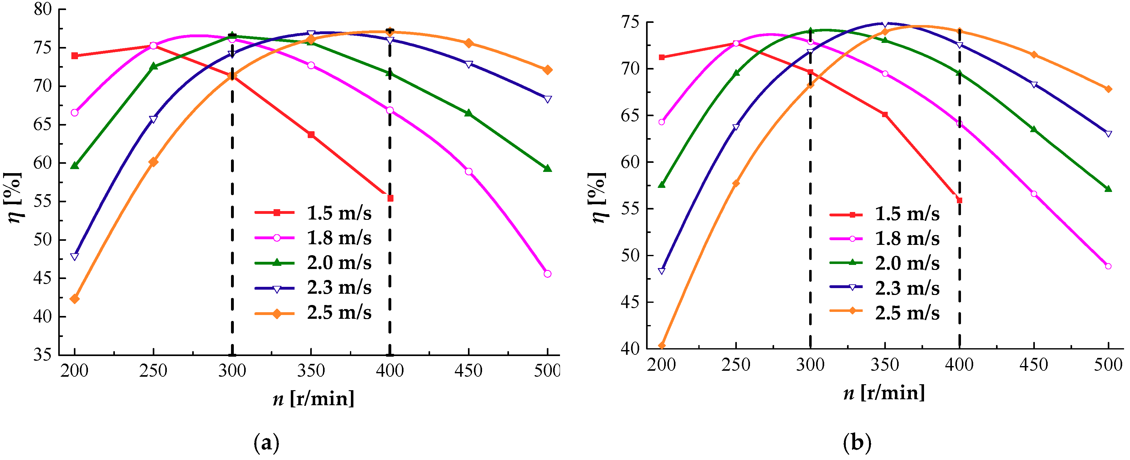
In this paper, the selection of the WTP optimal rotational speed was performed, considering the used hydraulic turbine only. The external characteristic parameters of both schemes without the pump are calculated in the speed range of 200~500 r/min and inlet velocity range of 1.5~2.5 m/s (Figure 6). For the same inlet velocity, the turbine efficiency is found to first increase and then decrease. Moreover, the increase in the inlet flow velocity gradually shifted the machine optimal rotating speed to higher values, where the high-efficiency region for the five investigated rotational speeds is concentrated within the range of 300~400 r/min, where the turbine efficiency can be above 70%. Hence, considering the actual operating conditions of the pump, n = 350 r/min was chosen as the optimal operating speed of the pump.

3.2. Determination of Connection Mode between Turbine and Pump

The CFD calculations were carried out for the two schemes under n = 350 r/min condition, and external parameters such as flow rate, efficiency, head, and power were obtained (Table 1 and Table 2). In the Table 1, 
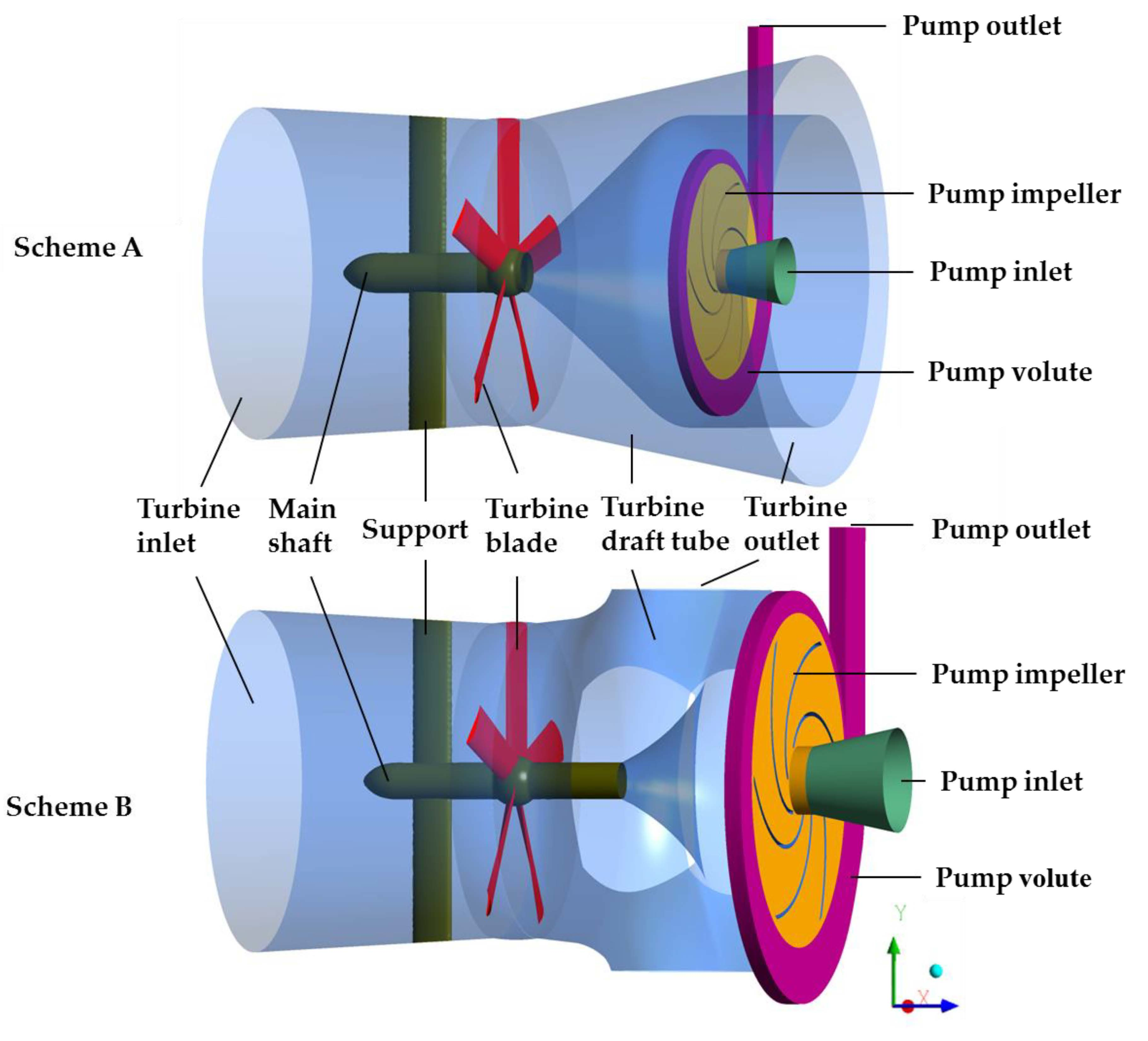
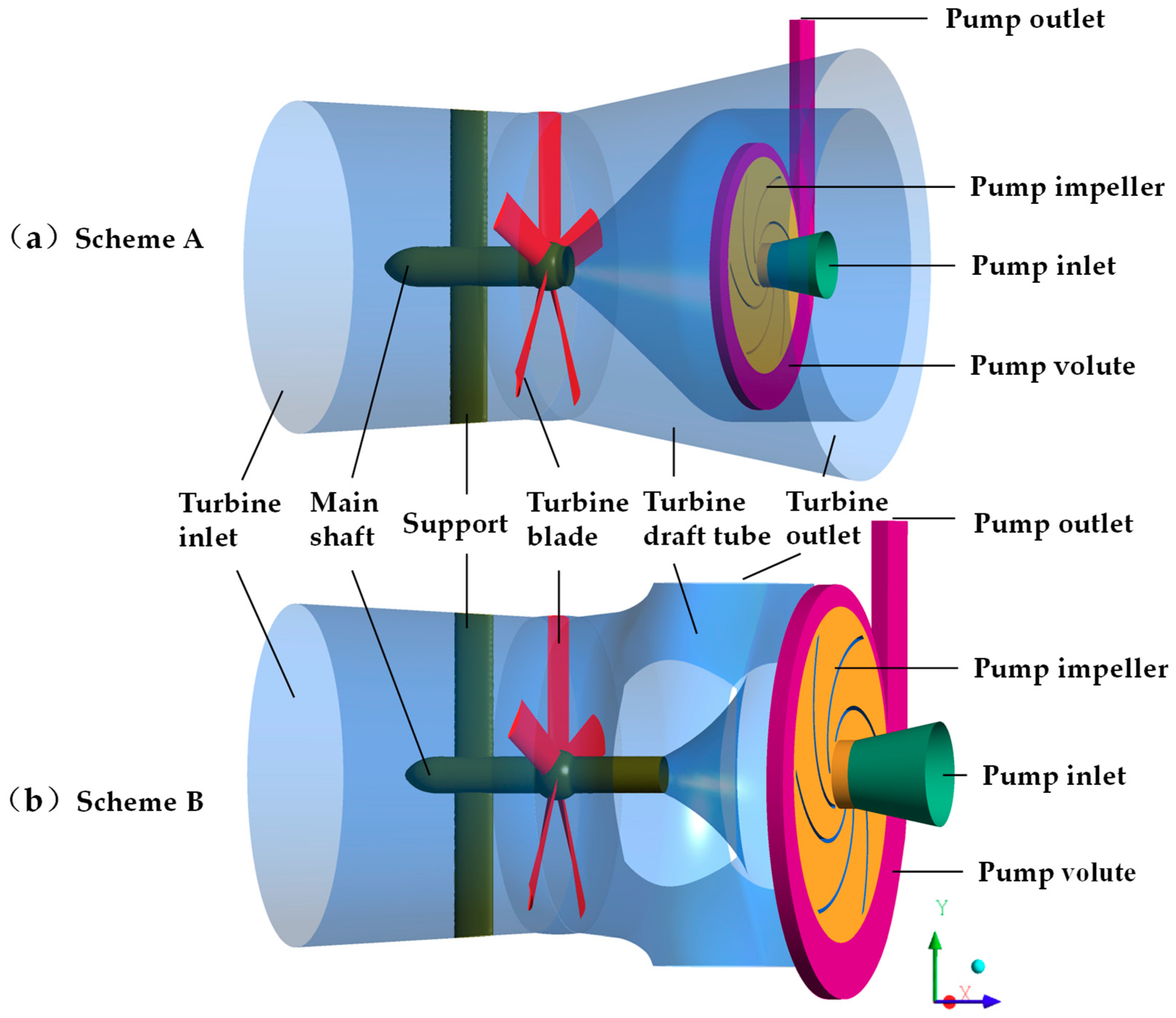
ζ is the percentage of head loss of outlet passage to the total head. Under the same velocity condition, the flow rate and output power of the two schemes are almost the same, and water head is not very different. However, the turbine efficiency of Scheme B with the separation of turbine and pump is significantly higher than that of Scheme A (Table 1). The amplitude of the efficiency increase is above 10% for the three inlet flow velocity conditions. The draft tube hydraulic losses for Scheme B are sharply lower than that in Scheme A, where they were specifically diminished by 15.47%, 14.64%, and 28.61%, at a flow velocity of 1.5, 2.0, and 2.5 m/s, respectively. When the pump moved to the outside of turbine, the pump’s outlet volute would not to go through the turbine’s draft tube, and the draft tube flow was no longer be interfered with. Therefore, the turbine efficiency improved dramatically as a result of obvious reduction of losses in its draft tube.
The discharge, shaft power, and pumping lift of the pump in Scheme B are far greater than that of Scheme A (Table 2). The maximum efficiency of the two schemes in Case 1 both reached 75%, but the flow rate in Scheme B is 4.5 times that of Scheme A, and the pumping lift is 2.26 m higher than that of Scheme A. For Case 2, the pump flow rate of Scheme A is only 25%, and the lift is 2.12 m lower than that of scheme B, but the efficiency of the two schemes are nearly the same. For Case 3, with close efficiency, the flow rate of Pump B is 3.7 times that of Pump A, and the lift is 1.89 m. higher than that of Scheme A.
Overall, although Scheme B increases the axial size of the WTP unit, the associated separation of pump from the turbine makes the flow in the turbine draft tube unaffected by the centrifugal pump position. Furthermore, in this scheme, the centrifugal pump geometry is no longer limited by the size of the connected turbine draft tube, which led to a proportional increase in the pump geometric dimensions. As a result, the pump’s discharge, pumping lift, and shaft power would naturally increase, while the efficiency would remain almost the same. Scheme B is obviously more in line with the WTP design principle, by which this machine is supposed to change large flow-low head energy into small flow-high head energy. Therefore, the performed design and selection processes finally adopt Scheme B at the expense of its counterpart, Scheme A, as the best-fitting one.

3.3. Improvement of Draft Tube for Hydrokinetic Turbine

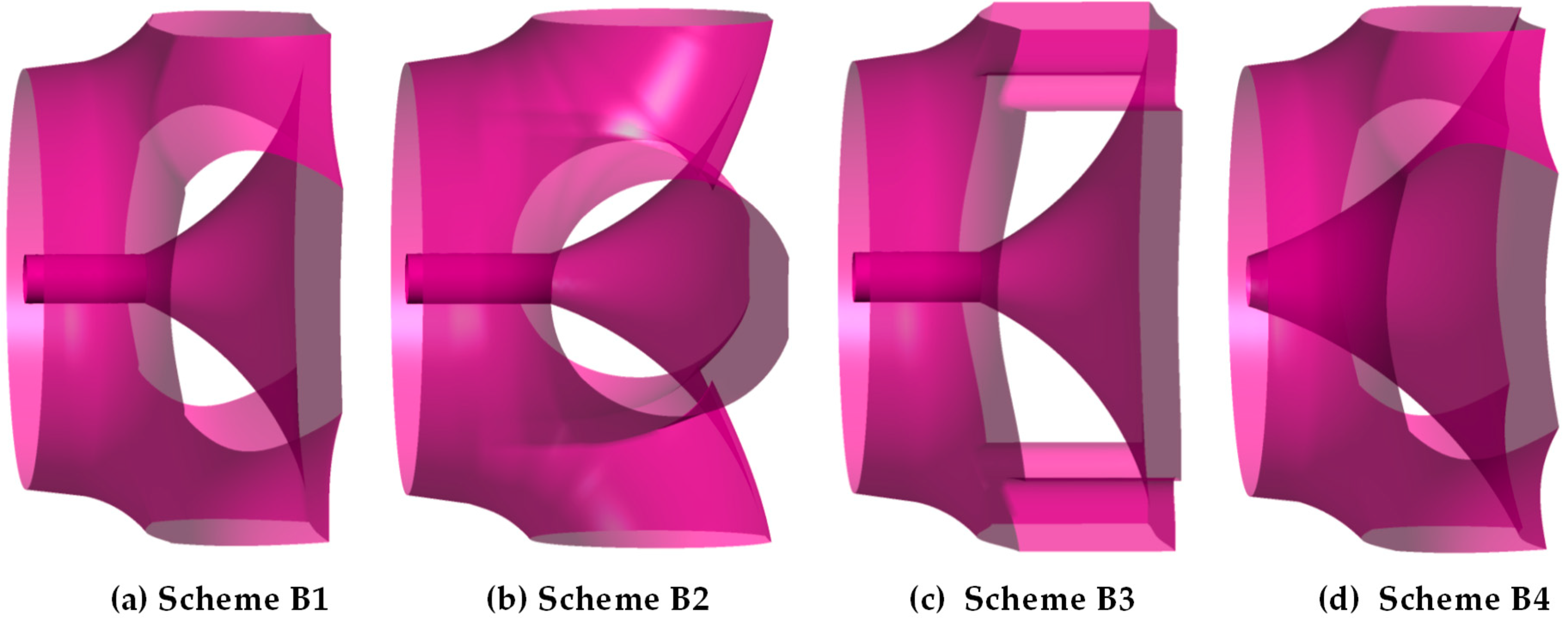
The draft tube is an important component for reaction turbines, where its main function is to convert the kinetic energy of turbine runner outlet flow into pressure energy and recover some of the flow energy. The shape of the draft tube has a vital influence on the operation stability and energy characteristics of the turbine unit, which explains why it should be optimized for the whole unit’s efficient and safe operations. In this part, four different shapes of a multi-elbow draft tube, as illustrated in 
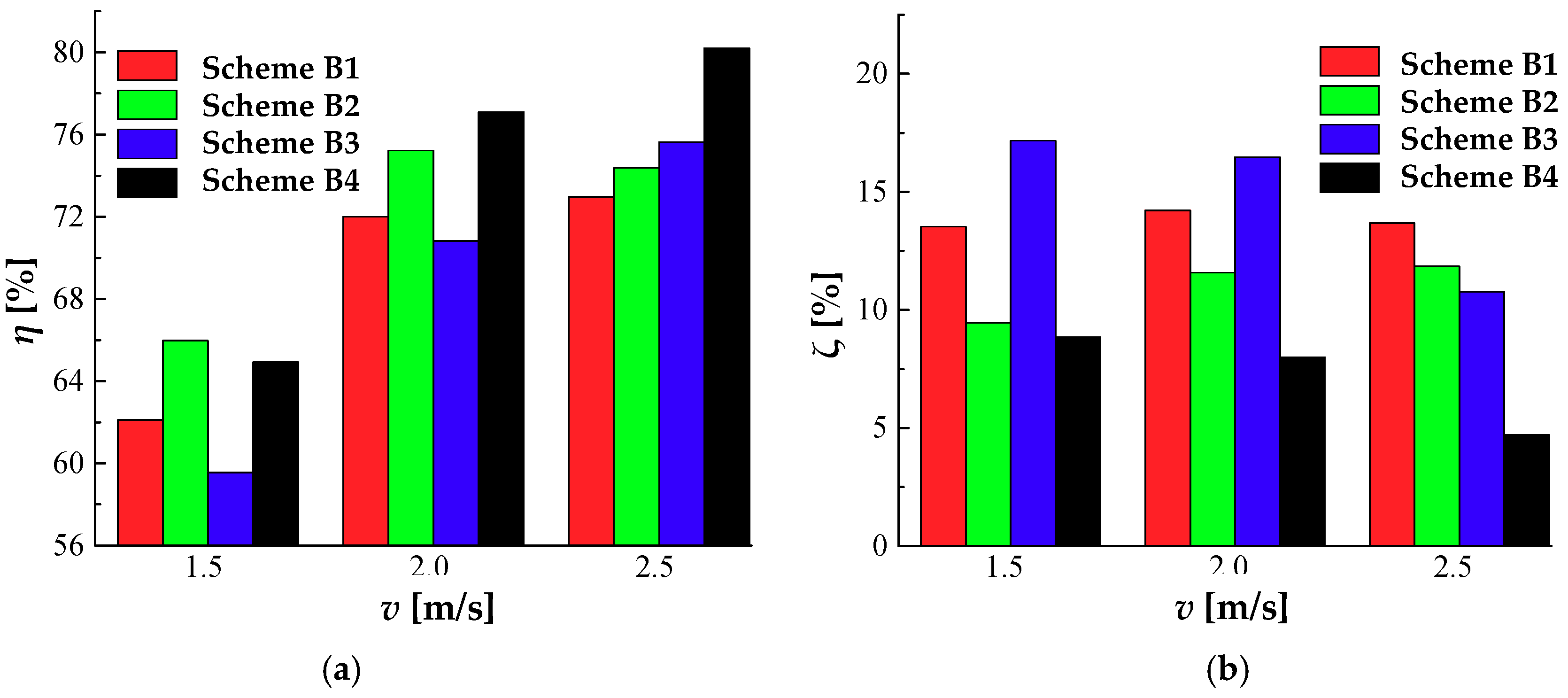
Figure 7, are tested. Scheme B1 is the preliminary design from Scheme B, while Scheme B4 is obtained based on the modification of internal profile from Scheme B1.
The overall efficiency of the four schemes globally improved with the inlet velocity increase from 1.5 to 2.5 m/s, where, specifically, there was a sharp efficiency increase from 1.5 to 2.0 m/s, and a comparatively slight increase was recorded when the inlet velocity grew from 2.0 to 2.5 m/s (Figure 8a). When (the inlet flow velocity) v = 1.5 m/s, the efficiency of the four schemes ranges between 60.0% and 67.0%.
The hydraulic losses in draft tubes of Scheme B2 and Scheme B4 are close and obviously lower than those of the other two schemes, and the efficiency of both schemes are above 65%. The inlet velocity of 2 m/s is similar to that of 1.5 m/s. The efficiency of scheme B4 is the highest, and the draft tube losses are the smallest (
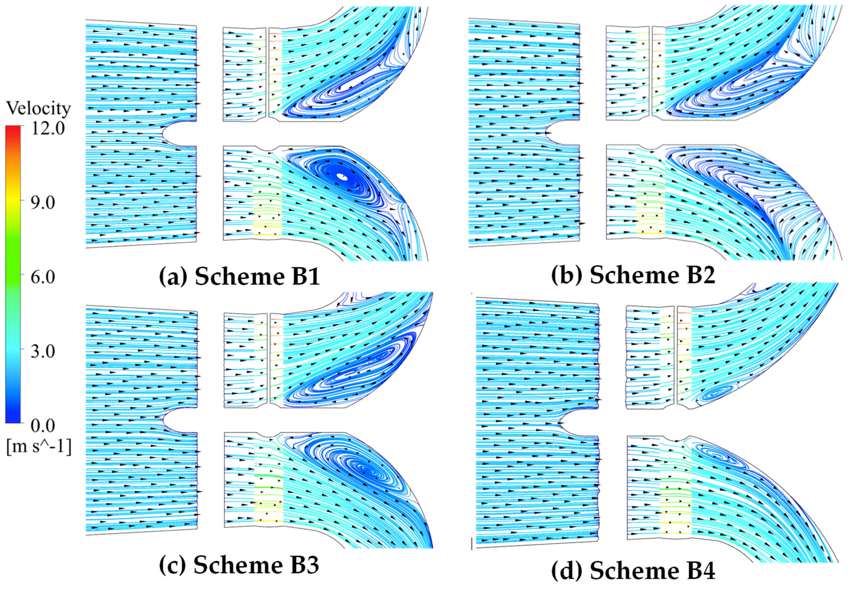
Figure 8b). The second one is scheme B2, whereas Scheme B3 is the worst. The major reason for large hydraulic losses is the development of flow vortices and reflux in the draft tube (Figure 9). For v = 2.5 m/s, the performance of Scheme B4 is the best, with over 80.0% efficiency and draft tube hydraulic losses less than 5%, followed by Scheme B3; Scheme B1 is the worst.
The noticed draft tube flow vortices are mainly caused by its geometric shape restriction. The flow direction changes from axial to radial, the velocity of the inner wall near the axis declines, and the velocity near the outer side of the tube increases, causing the water flow on the outer wall to shrink and the liquid flow inside to diffuse. Furthermore, due to the inertia of the water flow in the inner wall, the eddy current stagnant area appeared, leading the flow vortex structure formation and causing the turbulent kinetic energy dissipation to increase, which in turn resulted in the occurrence of certain hydraulic losses. These losses could be effectively cut down by changing the inner side profile of draft tube (Figure 9d). According to the design requirements, only at 1.5 m/s velocity, the turbine efficiency was less than 70%. Under the other two velocity conditions, the efficiency of Scheme B2 and Scheme B4 was much higher than 70%, and the comprehensive performance are better. However, the axial dimension of scheme B2 is larger than that of scheme B4, so scheme B4 is the better selection.

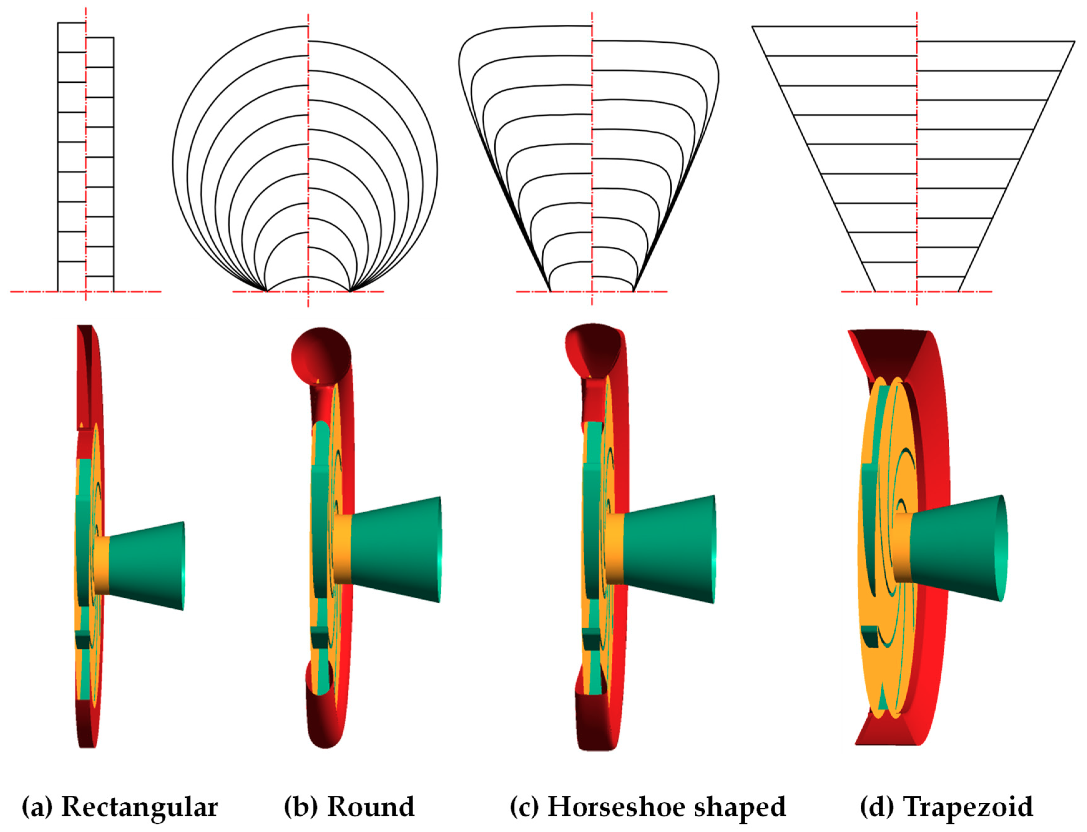
3.4. Volute Cross-Section Shape Selection for Pump

Volute cross-section shape is an important geometric parameter in volute design, and the profile of the volute has a certain effect on the hydraulic performance of the pump. In the initial design, the volute cross-section was rectangular, for its low manufacturing difficulty and cost, but in order to obtain the best performance of centrifugal pump design, four kinds of volute schemes were put forward, namely the rectangular volute, circular volute, trapezoidal volute, and horseshoe volute (Figure 10). The volute throat area kept constant at 6616 mm2, and the design of each cross-section followed the constant circumference rule. Moreover, all other parameters, like volute inlet width, volute outlet pipe diameter, and base circle diameter, were kept constant; only the cross-section shape was changed. In this part, the turbine and the centrifugal pump only shared the same rotational speed, but the two fluids had no contact with each other in space, so their flow states had little influence on each other. However, the total mesh number of the model was more than 3.85 million, in which the turbine model grid number accounts for nearly 70%. With the considerations of the PC’s computing capability and time resources, the pump was only calculated in this optimization.
A dimensionless loss rate was defined as Equation (6):
δ = P 2 P 3 P 2 P 1 × 100 %
where, δ is the relative loss rate in volute, %; P1 is inlet total pressure of pump, Pa; P2 is the inlet total pressure of volute, Pa; and P3 is outlet pressure of pump, Pa.
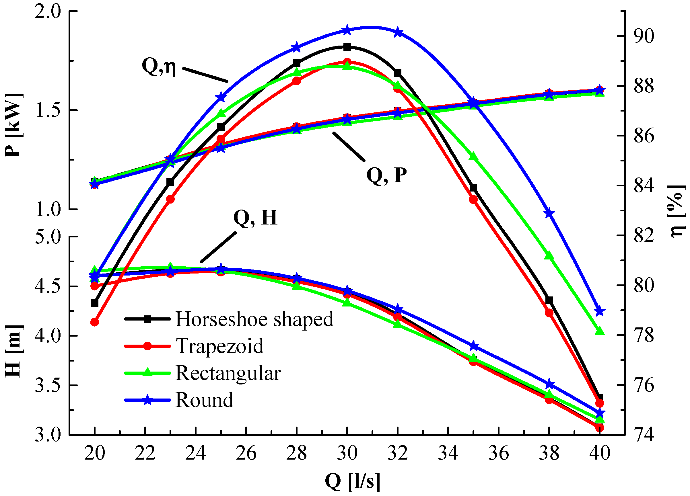
Figure 11 and Figure 12 show the curves of efficiency, pumping lift, shaft power, and relative hydraulic loss rate of volute, with different flow conditions. The efficiency of each of the four volute kinds is more than 80% of the design requirements. At the design point, the round-shaped design exhibited the highest efficiency, while the horseshoe-shaped one was the second highest, which was 0.67% lower than that of the round-shaped design. Pumps with a trapezoid- and rectangular-shaped volute have approximately the same efficiency. The efficiencies of rectangular- and round-shaped volutes are slightly higher than those of the trapezoidal- and horseshoe-shaped volutes, which made the curve become flatter and enlarged the high-efficiency area.
The heads of the four volute designs are almost the same (around 4.65 m), when the flow rate was 25 l/s. From this working condition to higher values, the head difference among different designs gradually became remarkable, but with quite little deflection. The lift of the round-, horseshoe-, and trapezoid-shaped volute is higher than 4.41 m, while the rectangular-shaped volute exhibited the lowest lift, which is about 0.1 m lower than the other three. The pumping lift of the round-shaped volute has the largest value under design and large-flow conditions, but the other three are not quite different, which is about 0.15 m lower than that of round volute. In small flow rate range, the rectangular volute generated the largest lift, the trapezoid is minimum, and the horseshoe and round volute basically share the same pumping lift. The shaft power with different cross-section varies little, which could be neglectable.
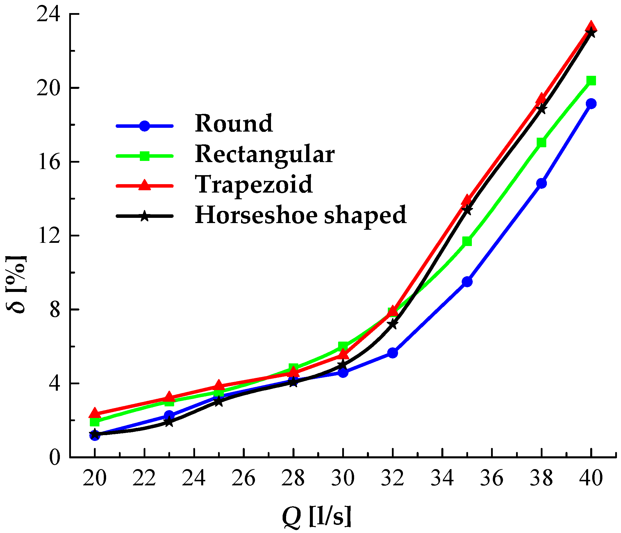
The hydraulic losses of the four volutes keep an upward tendency with the increase of discharge (Figure 12). In small flow rate, the loss of the round and horseshoe-shaped volute is the smallest, followed by the rectangular and trapezoid. The maximum difference occurred at the Q = 20 l/s point, where the loss ratio of the round- and horseshoe-shaped volute is 3.73% lower than that of the trapezoid. The loss rate of the round volute is the lowest, the rectangle one is the highest, and the difference between them is 1.4% at the design point Q = 30 l/s. For large flow rate, the loss of round-shaped design is the minimum, followed by the rectangular one, while the loss rate of both the trapezoidal and horseshoe-shaped volutes is close to the maximum. The largest difference appeared at Q = 35 l/s, where the loss rate of the round-shaped design is 2.2% lower than that of rectangular volute, and about 4% lower than that of trapezoid and horseshoe shapes. Hence, the round-shaped cross-section is accepted as a better scheme when considering the optimal efficiency and minimal losses.

3.5. Performance of the Designed RC-Driven WTP

Through the optimization process by CFD method, a better WTP device which can satisfy the design requirements was obtained.
As hydrokinetic turbine and pump are the two components of WTP, the efficiency of the WTP should be defined as follows:
η W = η t × η p
where ηw is the efficiency of WTP, and ηt and ηp are the efficiency of hydrokinetic turbine and centrifugal pump, respectively.
Table 3 and Table 4 provide results of external characteristics for WTP after optimization. From Table 3, the highest turbine’s efficiency of this design WTP unit is 81.18%, and the corresponding inlet velocity and output power of the turbine are 2.4 m/s and 4.21 kW, respectively. The pump’s maximum efficiency is 90.23%, while the corresponding water lift is 4.45 m, which is larger than the 4.0 m lift required by the design. Meanwhile, the pumping capacity of this centrifugal pump is 30 l/s, and the consumed shaft power is only 1.45 kW.
At the same speed, the pumping capacity increases with the increase of inlet flow velocity. At the same inlet velocity, the pumping capacity decreases with the increase of rotational speed, but the lift is increased, which could increase the capacity of water delivery by decreasing the speed. The highest efficiency of the WTP is 64.67% at inlet velocity and rotating speed of 1.8 m/s and 380 r/min, respectively, and the capacity and lift of pump are 30 l/s and 5.43 m, respectively, which was far enough to meet the demand. The WTP can run efficiently in most of the working conditions (Table 4).
The output of the turbine is always greater than the shaft power consumed by the pump, and the excess energy is mainly consumed as friction losses caused by the rotation of the bearing. If the friction loss is deducted, the output power of the turbine is still greater than the power consumed by the pump, and the water turbine part can automatically change speed to adapt; then, the discharge and the head of the pump will increase, resulting in an increase in the power of the shaft of the pump. The process of mutual compensation leads to a new balance, so there will be no unreasonable mismatch, which is also an advantage of the designed WTP, as explained in this paper.
Taking the best efficiency point (BEP) condition of WTP as an example,
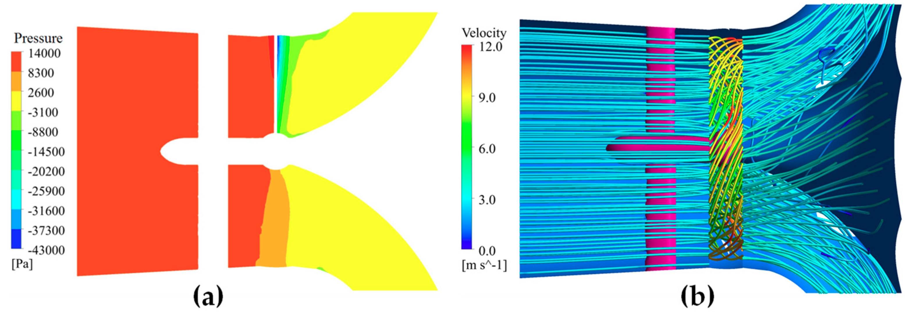
 Figure 13 and Figure 14 show the internal flow pattern of WTP on BEP. The static pressure distribution in the inlet passage is uniform and symmetrical, and the static pressure increases steadily along the flow direction. In addition, the static pressure in the outlet conduit is basically kept constant (Figure 13a). Simultaneously, the streamline of the whole turbine is straight and smooth, and only an extremely small backflow occurs close to the inner wall of the axis, which indicates that the flow regime was relatively better in the flow conduit (Figure 13b).
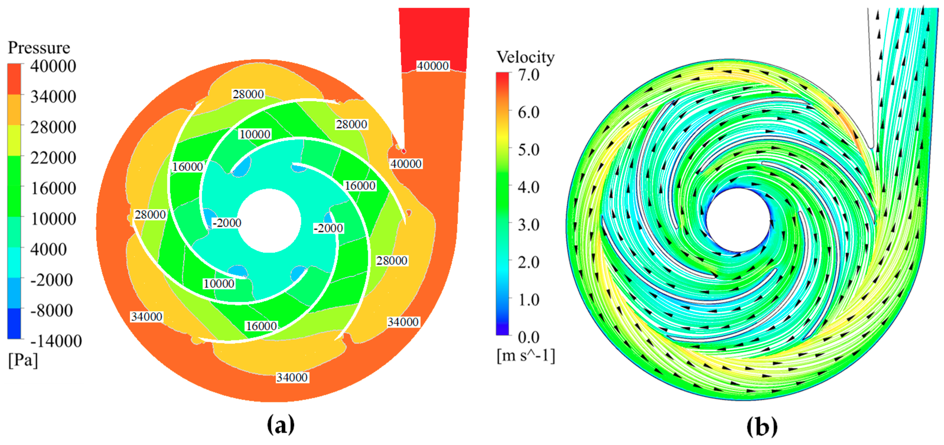
The volute was equivalent to a gradually expanding pipe for a centrifugal pump. According to Bernoulli’s equation, by passing through the rotating pump impeller, the flow velocity energy can be transformed into pressure energy, and then a large pressure gradient for the surrounding fluid will be created. Figure 14 displays the flow pattern in the center section of pump at BEP, where the velocities inside the impeller are in the rotating frame of reference. The static pressure and velocity gradually increase from the impeller inlet to outlet, where maximum static pressure zones appear near the outlet of each blade, whereas the minimum static pressure appear near the suction surface of the impeller blade’s leading edge. In addition, due to the relative motion between the high-speed rotating impeller and the stationary volute, the static pressure distribution within the volute presents an obvious asymmetry along the circumferential direction after the flowing liquid transfers from the impeller channel into the volute. The static pressure distribution in the volute is relatively consistent and the flow velocity is essentially stable. However, the velocity is comparatively higher near the volute inlet, owing to the influence of the high-speed water flow from the impeller. The flow velocity in the volute tends to be stable, thanks to the expansive design of the volute. The used centrifugal pump gives a good performance, and there is no bad flow regime occurrence, such as flow separation, reflux, or swirl, recorded.

4. Discussion

For MHK energy development, WTP is ideal for the energy capture from natural river flows. In this article, a type of WTP driven by a hydrokinetic turbine was described which belongs to MHK technologies. In line with this study’s results, it was demonstrated that the required flow velocity for the WTP, especially for the turbine compartment inlet, was considerably a large range from 1.5 to 2.5 m/s; and the whole system’s simple structure can reduce the manufacturing costs and difficulties. At present, there is still little research in the literature on hydraulic WTP in the world. However, hydraulic WTPs are mostly used for special purposes, such as thermal power units and rocket engines [8,35,36,37]. The kind of WTP design presented in this article pays more attention to the speed and ensures that the mount of the pumped water meets the design requirements. On the other hand, it does not pay special attention to the efficiency. In a study conducted by Wang et al. [17], a fire Turbopump supplying water from low-level water sources was designed, in which the turbine section was designed from a series of models, based on existing turbine theory. The turbine geometry was complex, with 15 main blades, 15 splitter blades, and 23 guide vanes, where the best efficiency of the fire turbopump was just 60%, while the turbine needed a large inlet flow rate to achieve the pump’s normal operations. A few conventional or new WTPs are extremely inefficient (less than 40%) to provide sufficient water to agricultural irrigation. Carravetta et al. [38] designed a new turbopump by coupling a pump and a pump as turbine in a water-supply network for energy-saving purposes. However, due to the system structure complexity, the turbine operating conditions were more stringent, and the average efficiency for this kind of WTP was lower than 45%. In addition, the development of the WTP is generally restricted by the fact that it cannot work or start itself in the plain area with low head or zero head.
If the presented water turbine pump was to be disassembled, where each of its components (turbine and pump) would be separately analyzed, the used designs would still present prominent advantages over other similar products. The turbine section of the RC-driven WTP in this study is partly similar to a conventional marine-current turbine. Our turbine’s output power could reach a high level for a fixed current velocity and rotor diameter, as compared to the ducted marine-current turbine [39]. For the pump section, the centrifugal pump used in this paper exhibited a maximum efficiency of more than 90%. This performance is outstanding among similar centrifugal pumps [40,41]. The kind of RC-driven WTP proposed in this paper skillfully combines the water turbine with a high-performance water pump, while keeping the operational requirements a bit low, which is of great practical significance for irrigation projects in plain areas.
It is worth mentioning that, in this research, the dynamic balance process of power when the pump and turbine work together was not accurately simulated. However, this problem could have been solved by catching the real-time power of the turbine and adjusting the speed of the pump through the torque balance equation by user-defined function, which most likely would lead to the realization of the dynamic balance of the unit operations. Despite its limitations, this study clearly proposed a new idea of no head run-of-river scheme development in MHK technologies. At the same time, the proposed WTP can also maintain advantages of the grid-independent use of renewable energy sources, just as it is the case for the traditional WTP. It is also environmentally friendly in regard to assuring fish safety, as it does not require dams or transmission lines.

5. Conclusions

In this study, using the CFD numerical simulation method, an RC-driven water turbine pump for plain areas was designed and developed in line with the designated design requirements, and then the model test was carried out for initial design testing and eventual improvement of individual parts so that the hydraulic performance of the WTP can meet all the design requirements. The main conclusions are as follows:
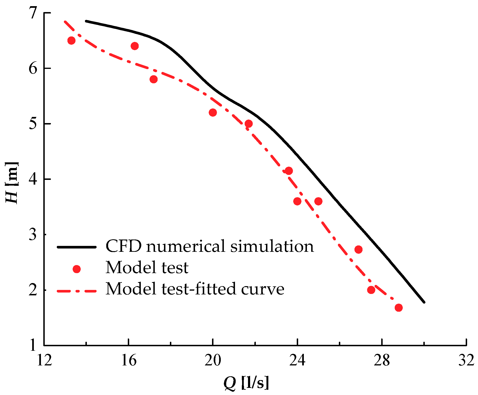
1. The initial model test was carried out to verify the accuracy of numerical simulation. The results show that the CFD results are consistent with the results of model test. The efficiency and pumping head had a minimum error range of ±5%. The major reasons for the recorded deviations are associated with the used computational grid characteristics and numerical turbulence model, as well as neglection of the mechanical transmission efficiency in CFD. The final selection of optimal rotating speed as 350 r/min is based on the numerical simulation method’s results.
2. Different connection means between the hydrokinetic turbine and pump were compared. When the centrifugal pump is transferred to the outlet of the multi-outlet elbow draft tube, the hydraulic loss of outlet channel could be reduced by more than 14% and the hydrokinetic turbine efficiency could rise up by over 10%. Meanwhile, in this scenario, the pump size is not restricted by turbine draft tube; therefore, the quantity of pumped water and lift would greatly increase. These arrangements realized the separation of turbine and pump flow passages and decreased the hydraulic impact of the turbine outlet wake flow on the pump inlet flow conditions, thus ensuring the pump’s efficient operations. Furthermore, the internal reflux area could be efficaciously abated by changing the inner profile line of elbow section.
3. The effects of volute’s cross-section shape on the pump performance were analyzed, and it was observed that the volute cross-section exercises a certain influence on pump hydraulic characteristics, especially on the volute hydraulic loss rate. Its effect was, however, found to vary with the flow discharge. The highest efficiency is reached with a round volute cross-section, and the second highest was realized by the horseshoe-shaped volute, which is 0.67% lower than that of the round shape. Pump with rectangular- and trapezoid-shaped cross-sections have achieved nearly the same efficiency at design point. Moreover, the high efficiency range of round and rectangular shape is wider. Round cross-sectional shape is chosen as the best option for the volute to achieve high efficiency.
4. The designed RC-driven WTP presented in this paper is feasible and highly efficient. It has a wide range of application areas, including the water stream, rivers, and channels. Its blades have no special flow direction requirements. Therefore, the RC-driven WTP can make full use of the scattered but large and wide-scale hydro and kinetic energy, to achieve sustainable energy development. WTPs offer the advantages of saving fuel and full utilization of hydraulic resources. They are also simple to operate, easy to manufacture, easy to maintain, highly efficient, and low in cost, on top of having a good running performance, as compared to other irrigation and drainage machinery.

Author Contributions

Conceptualization, D.Z. and H.C.; methodology, D.Z.; software, H.C.; validation, Y.Z., K.K. and A.Y.; formal analysis, H.C., K.K., and A.Y.; resources, D.Z.; writing—original draft preparation, D.Z. and H.C.; writing—review and editing, D.Z., Y.Z., and M.B.; supervision, D.Z.; funding acquisition, D.Z. and A.Y.

Funding

The author(s) disclosed receipt of the following financial support for the research, authorship, and/or publication of this article. This article was funded by the National Natural Science Foundation of China (No. 51979086; No. 51839008; and No. 51806058).

Acknowledgments

The authors would like to acknowledge the financial support of Hohai University and National Natural Science Foundation of China. Many thanks to the valuable discussions and suggestions from Prof. Zhiqun Daniel Deng in Pacific Northwest National Laboratory, USA, and Dr. Norbert Mueller in Michigan State University, USA.

Conflicts of Interest

The author(s) declare no potential conflicts of interest with respect to the research, authorship, and/or publication of this article.

Abbreviation

u fluid velocity
x i Cartesian coordinate component in x direction
ρ fluid density
x j Cartesian coordinate component in y direction
F i body force per unit volume
p pressure
μ viscosity
nrotational speed
vturbine inlet velocity
Qtturbine discharge
Ptoutput of turbine
ηtturbine efficiency
ζpercentage of head loss of outlet passage to the total head.
Qppump discharge
Pppower of pump
Hplift of pump
ηppump efficiency
ηWWTP efficiency
δ loss rate in volute
P 1 inlet total pressure of pump
P 2 inlet total pressure of volute
P 3 outlet total pressure of pump
BEPbest efficiency point
CFDcomputational fluid dynamics
MHKmarine and hydrokinetics
WTPwater turbine pump
RCriver-current
S–ASpalart–Allmaras

References

  1. Owusu, P.A.; Asumadu-Sarkodie, S. A review of renewable energy sources, sustainability issues and climate change mitigation. Cogent Eng. 2016, 3, 1167990. [Google Scholar] [CrossRef]
  2. Matulionytė, J.E. Renewable energy in the context of sustainable development. Sustain. Dev. Strategy Pract. 2012, 1, 123–132. [Google Scholar]
  3. Global Energy & CO2 Status Report—The Latest Trends in Energy and Emissions in 2018. Available online: https://www.iea.org/geco/renewables/ (accessed on 22 March 2019).
  4. Rezghi, A.; Riasi, A. The interaction effect of hydraulic transient conditions of two parallel pump-turbine units in a pumped-storage power plant with considering “S-shaped” instability region: Numerical simulation. Renew. Energy 2018, 118, 896–908. [Google Scholar] [CrossRef]
  5. Dubbs, L.; Keeler, A.G.; O’Meara, T. Permitting, risk and marine hydrokinetic energy development. Electr. J. 2013, 26, 64–74. [Google Scholar] [CrossRef]
  6. Bedard, R. Prioritized Research, Development, Deployment and Demonstration (RDD&D) Needs: Marine and Other Hydrokinetic Renewable Energy; Electric Power Research Institute: Palo Alto, CA, USA, 2008. [Google Scholar]
  7. U.S. Department of Energy, Wind and Water Power Technologies Office, Marine and Hydrokinetics Energy Projects. Marine and Hydrokinetic Research and Development; March 2014. Available online: https://www.energy.gov/sites/prod/files/2014/04/f15/mhkprojectsreport.pdf (accessed on March 2014).
  8. Intriago Zambrano, J.C.; Michavila, J.; Arenas Pinilla, E.; Diehl, J.C.; Ertsen, M.W. Water Lifting Water: A Comprehensive Spatiotemporal Review on the Hydro-Powered Water Pumping Technologies. Water 2019, 11, 1677. [Google Scholar] [CrossRef]
  9. Nourbakhsh, A.; Jaumotte, A.; Hirsch, C.; Parizi, H.B. Turbopumps and Pumping Systems; Springer Science & Business Media: Berlin, Germany, 2007. [Google Scholar]
  10. Weng, A.H. Understanding the water-turbine pump. World Pumps 1986, 238, 196–197. [Google Scholar]
  11. Means, H.E. Turbine Driven Pump. U.S. Patent No. 2,839,005, 17 June 1958. [Google Scholar]
  12. Li, J.; Gao, H.; Hu, X. An Economic Analysis of a Turbine-Driven Feed Water Pump. Int. J. Simul. Syst. Sci. Technol. 2016, 17. [Google Scholar] [CrossRef]
  13. Sant, T.; Buhagiar, D.; Farrugia, R.N. Offshore floating wind turbine-driven deep sea water pumping for combined electrical power and district cooling. J. Phys. Conf. Ser. 2014, 524, 012074. [Google Scholar] [CrossRef]
  14. Bouzayani, N.; Galanis, N.; Orfi, J. Thermodynamic analysis of combined electric power generation and water desalination plants. Appl. Eng. 2008, 29, 624–633. [Google Scholar] [CrossRef]
  15. Essam, S.M.; Papadakis, G.; Mathioulakis, E.; Belessiotis, V. An experimental comparative study of the technical and economic performance of a small reverse osmosis desalination system equipped with an hydraulic energy recovery unit. Desalination 2006, 194, 239–250. [Google Scholar]
  16. Gilau, A.M.; Small, M.J. Designing cost-effective seawater reverse osmosis system under optimal energy options. Renew. Energy 2008, 33, 617–630. [Google Scholar] [CrossRef]
  17. Wang, L.J.; Yuan, Y.; Xue, L. Research on Design of High-efficiency Fire Turbopump Supplying Water from Low-level Water Resources. Adv. Mater. Res. 2013, 694, 652–658. [Google Scholar] [CrossRef]
  18. Yannopoulos, S.; Lyberatos, G.; Theodossiou, N.; Li, W.; Valipour, M.; Tamburrino, A.; Angelakis, A. Evolution of water lifting devices (pumps) over the centuries worldwide. Water 2015, 7, 5031–5060. [Google Scholar] [CrossRef]
  19. Zhou, D.Q.; Shen, P.F.; Chen, H.X.; Wang, B. A Micro-Head River-Current Driven Water Turbine Pump. Chinese Patent No. CN201510422804.5, 23 June 2017. [Google Scholar]
  20. Zhou, D.Q.; Deng, Z.Q. Ultra-low-head hydroelectric technology: A review. Renew. Sustain. Energy Rev. 2017, 78, 23–30. [Google Scholar] [CrossRef]
  21. Zhou, D.Q.; Chen, H.X.; Zhong, L.J.; Zheng, Y. A New Type Runner of Marine Current Generating Turbine with a Diffuser. Chinese Patent No. CN201310496139.5, 21 October 2015. [Google Scholar]
  22. Valencia, E.; Granja, V.; Palacios, J.; Poveda, R.; Cando, E.; Hidalgo, V. Uncertainty analysis of a test-rig for centrifugal compressors. Rev. Politécnica 2015, 35, 19. [Google Scholar]
  23. Chen, H.X.; Zheng, Y.; Zhou, D.Q.; Shen, P.F.; Liu, H.W. Design and development of an eco-gate pump installation based on computational fluid dynamics. Proc. Inst. Mech. Eng. C J. Mech. Eng. Sci. 2017, 231, 2636–2649. [Google Scholar] [CrossRef]
  24. Qian, Z.D.; Wang, F.; Guo, Z.W.; Lu, J. Performance evaluation of an axial-flow pump with adjustable guide vanes in turbine mode. Renew. Energy 2016, 99, 1146–1152. [Google Scholar] [CrossRef]
  25. Saeed, R.A.; Galybin, A.N. Simplified model of the turbine runner blade. Eng. Fail. Anal. 2009, 16, 2473–2484. [Google Scholar] [CrossRef]
  26. Kversteeg, H.K.; Malalasekera, W. An Introduction to Computational Fluid Dynamics: The Finite Volume Method; Wiley: New York, NY, USA, 1995; pp. 4–30. [Google Scholar]
  27. Spalart, P.R.; Allmaras, S.R. A one equation turbulence model for aerodynamic flows. Rech. Aerosp. 1994, 1, 5–21. [Google Scholar]
  28. Kostić, Č. Review of the Spalart-Allmaras turbulence model and its modifications to three-dimensional supersonic configurations. Sci. Tech. Rev. 2015, 65, 43–49. [Google Scholar] [CrossRef]
  29. Cui, B.L.; Lin, Y.G.; Jin, Y.Z. Numerical simulation of flow in centrifugal pump with complex impeller. J. Sci. 2011, 20, 47–52. [Google Scholar] [CrossRef]
  30. Zeng, Y.; Liu, X. Simulation on blade duct vortex in a Francis turbine runner based on S-A model. Appl. Mech. Mater. 2013, 444–445, 476–478. [Google Scholar]
  31. Fluent Inc. Gambit Tutorial Guide (Technical Reference); Fluent Inc.: Lebanon, NH, USA, 2007. [Google Scholar]
  32. Wu, J.C.; Shimmei, K.; Tani, K.; Niikura, K.; Sato, J. CFD-Based design optimization for hydro turbines. J. Fluid Eng. 2007, 129, 159–168. [Google Scholar] [CrossRef]
  33. Rahimian, M.; Walker, J.; Penesis, I. Numerical assessment of a horizontal axis marine current turbine performance. Int. J. Mar. Energy 2017, 20, 151–164. [Google Scholar] [CrossRef]
  34. Barrio, R.; Fernandez, J.; Blanco, E.; Parrondo, J.; Marcos, A. Performance characteristics and internal flow patterns in a revers running pump-turbine. Proc. Inst. Mech. Eng. C J. Mech. Eng. Sci. 2012, 226, 695–708. [Google Scholar] [CrossRef]
  35. Lee, H.; Shin, J.H.; Choi, C.H. Experimental investigation of the turbine in a turbopump for a liquid rocket engine with a 75-ton force thrust. Trans. Korean Soc. Mech. Eng. B 2018, 42, 519–524. [Google Scholar] [CrossRef]
  36. Shi, X.X.; Wang, P.Y.; Li, H.J. Research on the bestturbine driven feed water pump operation of thermal powerunit. Electr. Power Sci. Eng. 2015, 31, 10–14. [Google Scholar]
  37. Pace, G.; Valentini, D.; Pasini, A.; Torre, L.; Hadavandi, R.; D’agostino, L. Inducer and centrifugal pump contributions to the rotordynamic fluid forces acting on a space turbopump. J. Fluids Eng. 2018, 140, 021104. [Google Scholar] [CrossRef]
  38. Carravetta, A.; Antipodi, L.; Golia, U.; Fecarotta, O. Energy saving in a water supply network by coupling a pump and a pump as turbine (PAT) in a turbopump. Water 2017, 9, 62. [Google Scholar] [CrossRef]
  39. Laurens, J.M.; Ait-Mohammed, M.; Tarfaoui, M. Design of bare and ducted axial marine current turbines. Renew. Energy 2016, 89, 181–187. [Google Scholar] [CrossRef]
  40. Karassik, I.J. Centrifugal Pump Clinic, Revised and Expanded; CRC Press: Boca Raton, FL, USA, 2017. [Google Scholar]
  41. Shankar, V.K.A.; Umashankar, S.; Paramasivam, S.; Hanigovszki, N. A comprehensive review on energy efficiency enhancement initiatives in centrifugal pumping system. Appl. Energy 2016, 181, 495–513. [Google Scholar] [CrossRef]
Figure 1. Two general design schemes of river-current (RC)-driven water turbine pump (WTP). (a) Scheme A; (b) Scheme B.
Energies 12 04264 g001
Figure 2. Photos of WTP unit: (a) physical model of the WTP and (b) photo of the unit installation.
Energies 12 04264 g002
Figure 3. The CAD representation of the test loop: 1—tail water tank, 2—pressure tank, 3—pressure gauge, 4—three-way valve, 5—model hydrokinetic WTP, 6—cylinder, 7—electric valve, 8—variable speed circulating pump, 9—butterfly valve, 10—electromagnetic flow meter, 11—butterfly valve, 12—charging pump, 13—motor, 14—butterfly valve, 15—butterfly valve, and 16—electric valve.
Energies 12 04264 g003
Figure 4. Grid independence curves: (a) turbine condition and (b) pump condition.
Energies 12 04264 g004
Figure 5. Comparisons of numerical simulation and model test results at v = 2 m/s.
Energies 12 04264 g005
Figure 6. Influences of different rotational speed on efficiency of the water turbine: (a) Scheme A and (b) Scheme B.
Energies 12 04264 g006
Figure 7. Schematic diagrams of different multiple-outlet elbow-shaped draft tubes. (a) Scheme B1; (b) Scheme B2; (c) Scheme B3 and (d) Scheme B4.
Energies 12 04264 g007
Figure 8. Efficiency and draft tube hydraulic loss of different turbine with different velocity. (a) The overall efficiency of the four schemes; (b) the hydraulic losses in draft tubes of the four schemes.
Energies 12 04264 g008
Figure 9. Velocity distribution of vertical section within different turbine at v = 2.0 m/s. (a) Scheme B1; (b) Scheme B2; (c) Scheme B3 and (d) Scheme B4.
Energies 12 04264 g009
Figure 10. Four volutes with different cross-sections.
Energies 12 04264 g010
Figure 11. Performance curves of pump with different volutes.
Energies 12 04264 g011
Figure 12. Loss rate of pump with different volutes.
Energies 12 04264 g012
Figure 13. Flow pattern in the WTP at BEP: (a) static pressure distribution in the vertical section of turbine and (b) 3D streamline in the turbine.
Energies 12 04264 g013
Figure 14. Flow pattern in the WTP at BEP: (a) static pressure distribution in center section of pump and (b) velocity distribution in the center section of pump.
Energies 12 04264 g014
Table 1. Influences of different connection way on external parameters of the turbine.
Schemev (m/s)Qt (l/s)Pt (kW)ηt (%)ζ (%)
A1.5340.850.9251.5529.00
2.0454.472.6160.0828.85
2.5568.094.5458.6942.28
B1.5340.850.9262.1013.53
2.0454.472.6272.0014.21
2.5568.094.5972.9713.67
Table 2. Influences of different connection way on the external parameters of the pump.
SchemeQp (l/s)Hp (m)Pp (kW)ηp (%)
A4.002.560.1375.07
5.002.110.1472.83
6.001.640.1564.08
B18.004.821.0977.82
20.004.231.1472.91
22.003.531.2063.67
Table 3. Calculation on the external characteristics of the WTP at n = 350 r/min.
v (m/s)Qt (l/s)Pt (kW)ηt (%)Qp (l/s)Hp (m)Pp (kW)ηp (%)
1.5340.850.9164.92154.830.8978.50
1.8409.041.8772.90254.671.3187.53
2.0454.472.6377.08304.451.4590.23
2.2499.943.4380.87334.151.5089.62
2.4545.394.2181.18383.511.5882.88
2.5568.094.5980.21403.221.6078.95
Table 4. The external characteristics of the WTP.
v (m/s)Qt (l/s)Pt (kW)ηt (%)n (r/min)Qp (l/s)Hp (m)Pp (kW)ηp (%)ηW (%)
1.5340.850.9164.92350154.830.8978.5048.61
1.6363.591.2068.19350224.621.1884.5057.62
1.7386.321.5270.77350334.151.5089.6163.42
1.8409.041.8471.87360403.771.8082.1959.07
1.8409.041.8070.90370354.621.7789.4863.44
1.8409.041.7870.41380305.431.7491.8464.67
1.8409.041.7368.66390255.811.6984.2457.84
1.8409.041.6967.86400206.251.6673.8750.13
1.9431.772.0870.13400306.082.0487.7161.51
1.9431.772.1370.90391354.602.0975.5753.58
2.0454.472.4770.70415356.352.4290.0963.69
2.0454.472.4169.59428307.002.3687.2160.69
2.0454.472.3267.94445257.432.2879.9254.30

