Double-Layer E-Structure Equalization Circuit for Series Connected Battery Strings

Abstract
1. Introduction
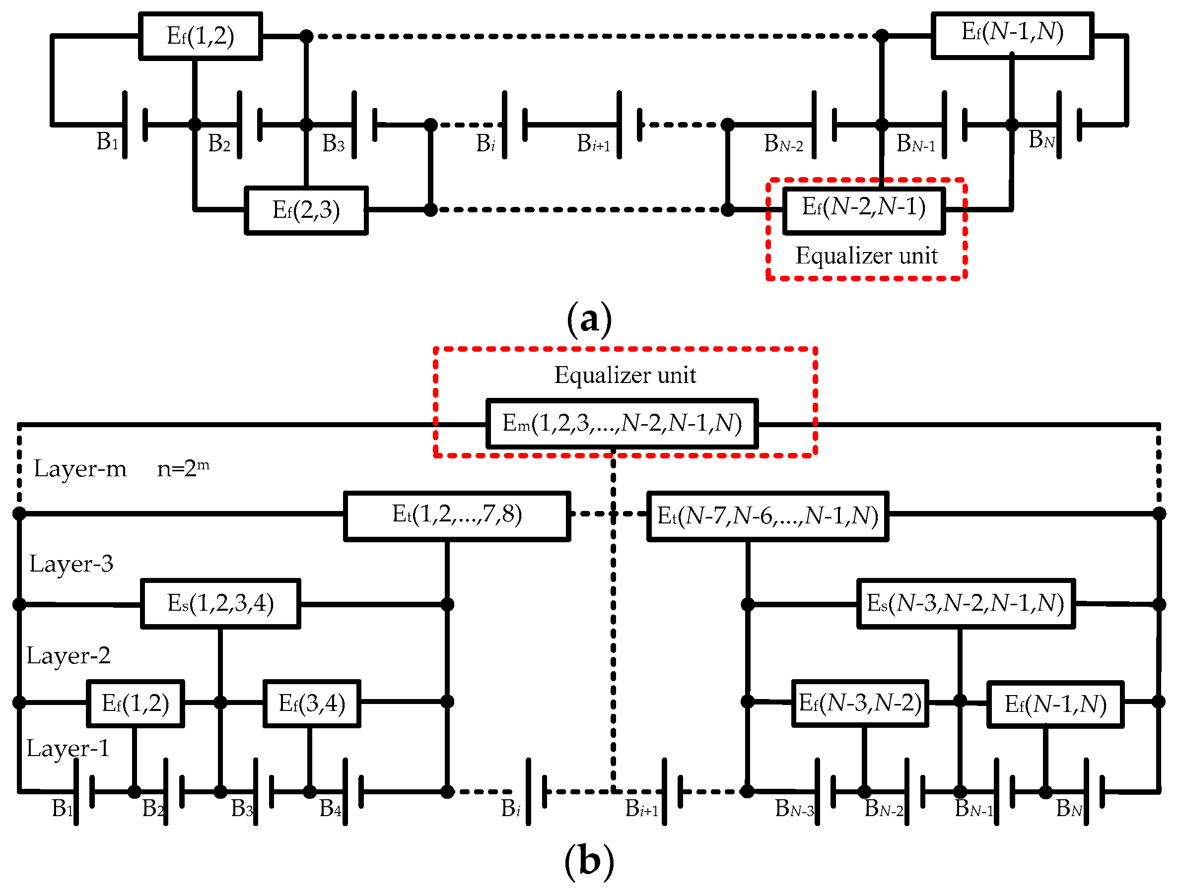
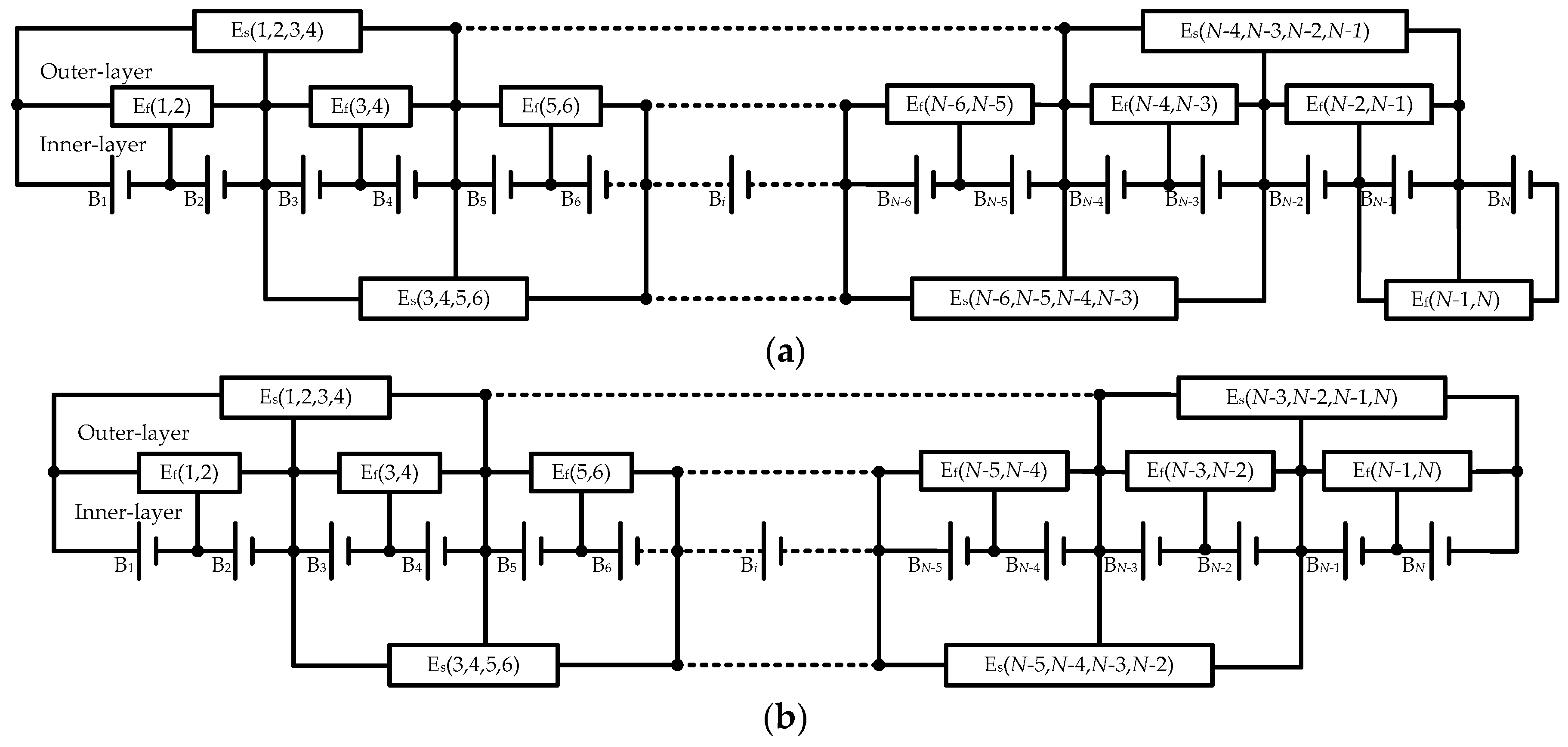
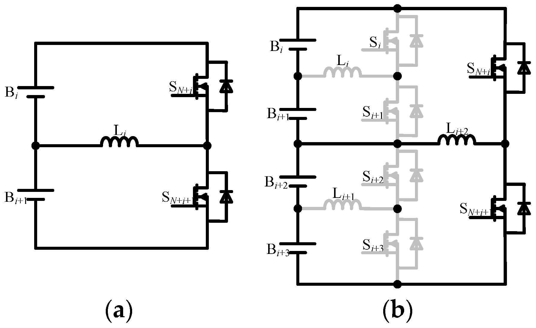
2. Structures of Proposed Equalizer
- All diodes, switches, and inductors employed in proposed equalizer are ideal;
- Each inductor has the identical parameter, i.e., L = L1 = L2 = L3 = … = L2N-2;
- Cell voltages are constant during one switching period;
- All of the buck–boost converters are operated in discontinuous conduction mode (DCM)
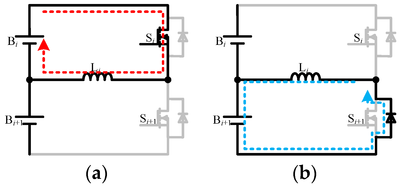
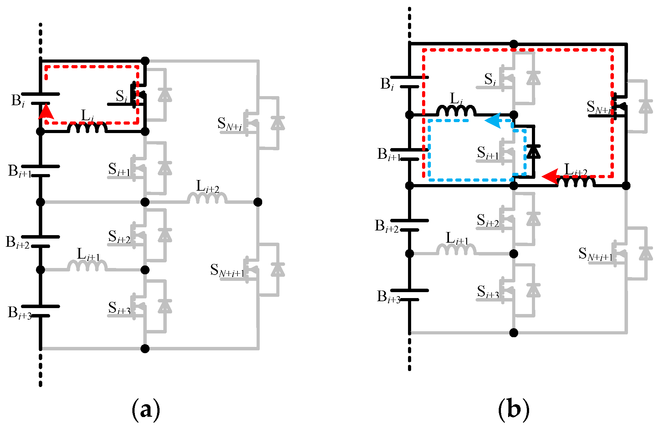
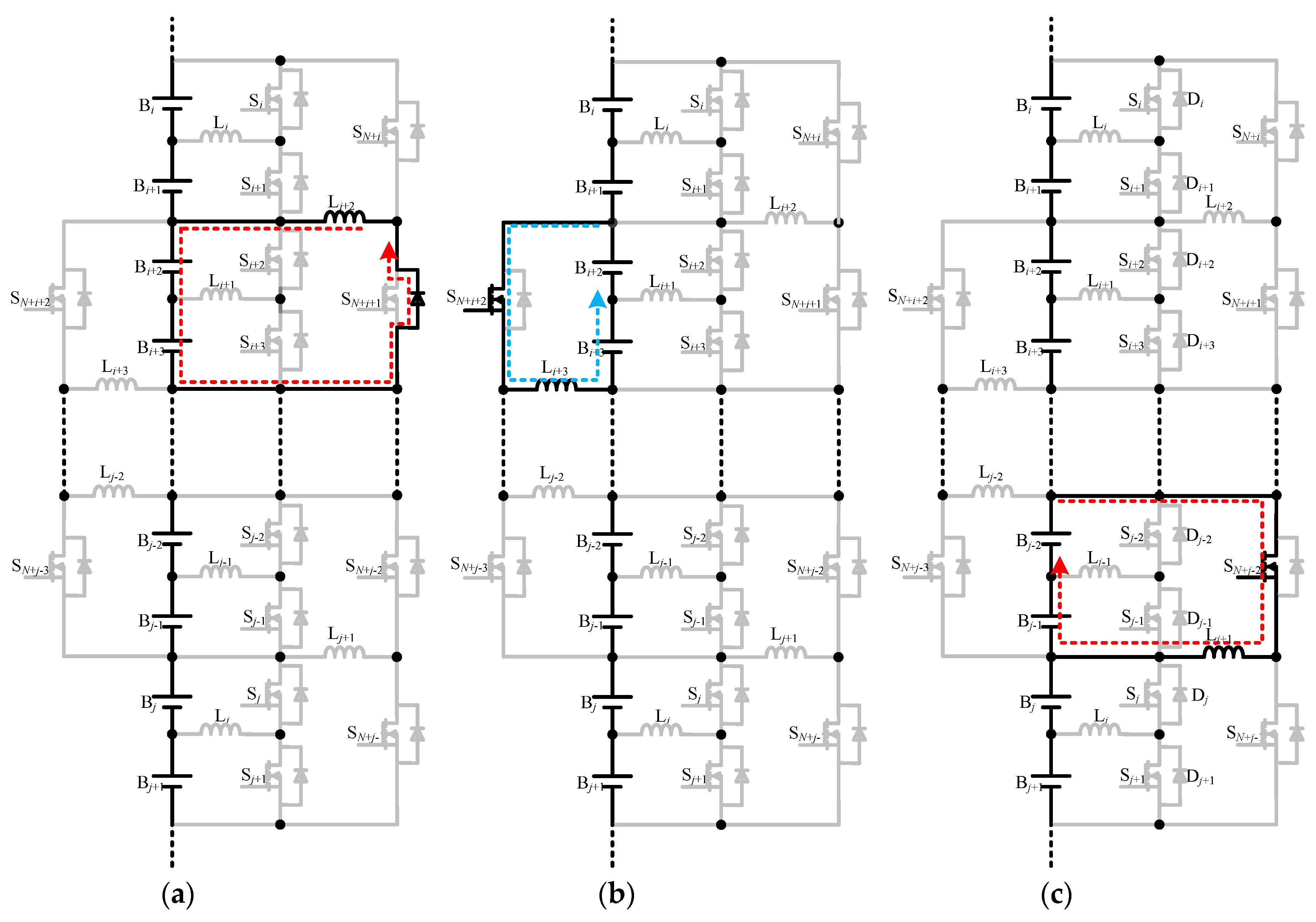
3. Equalization Principles
3.1. First Stage Equalization
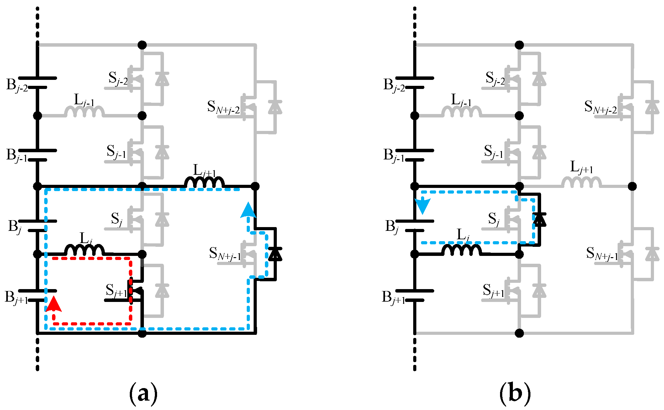
3.2. Second Stage Equalization
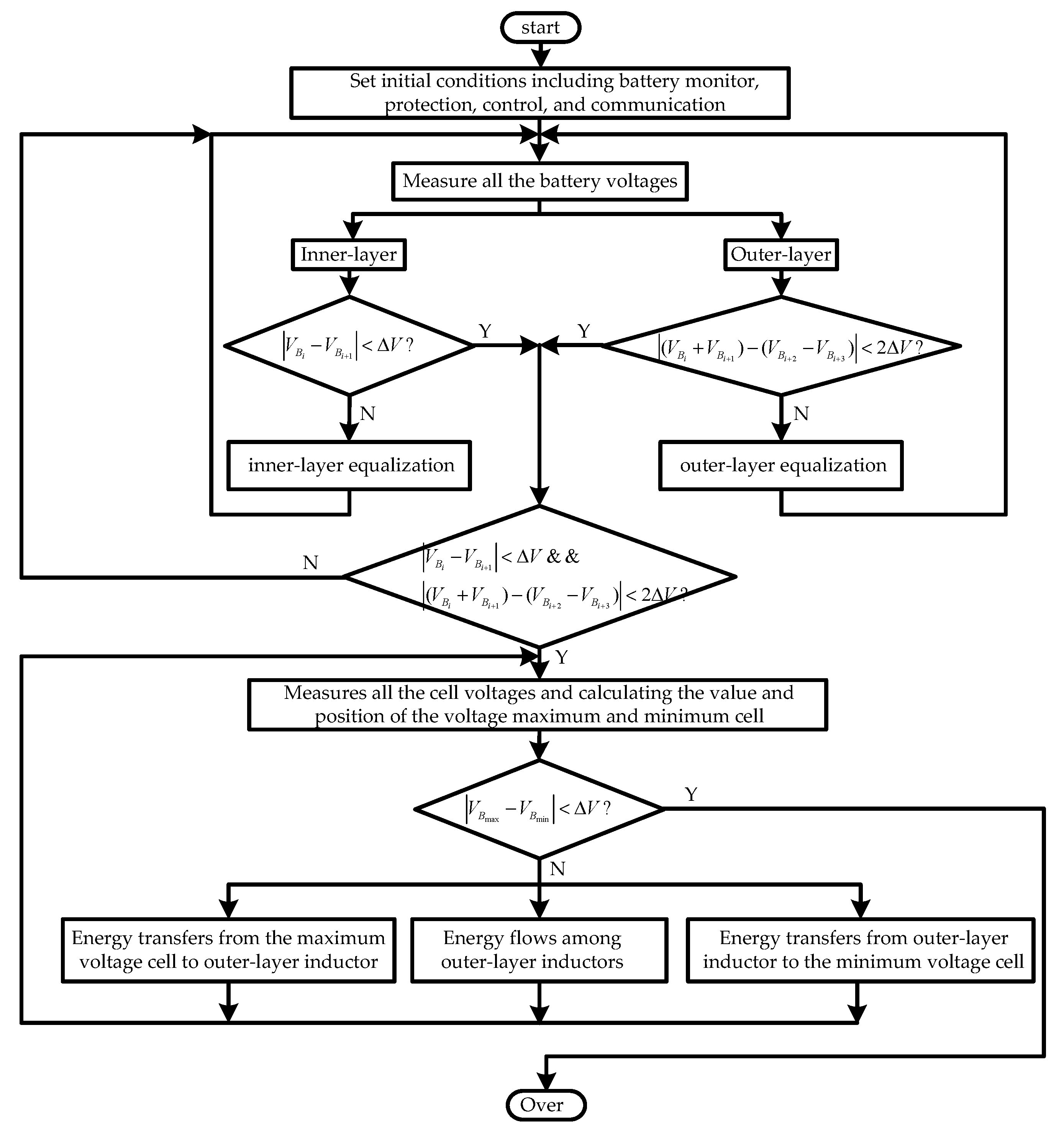
4. Equalization Control Strategy
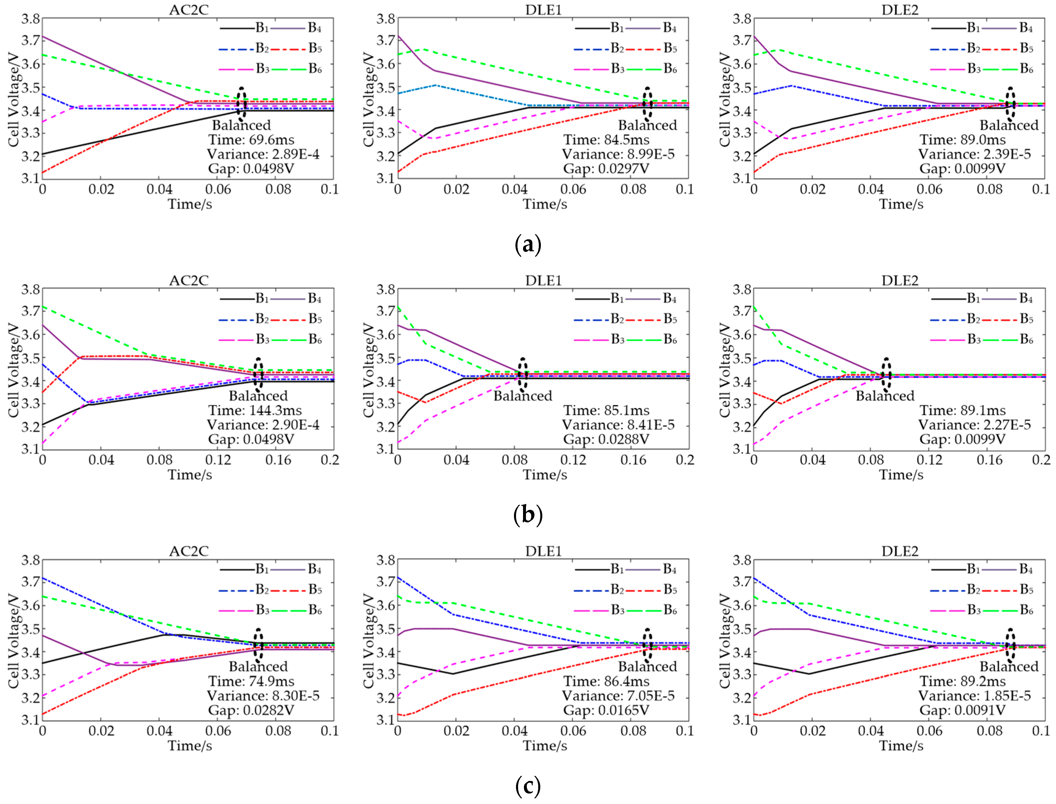
5. Simulation
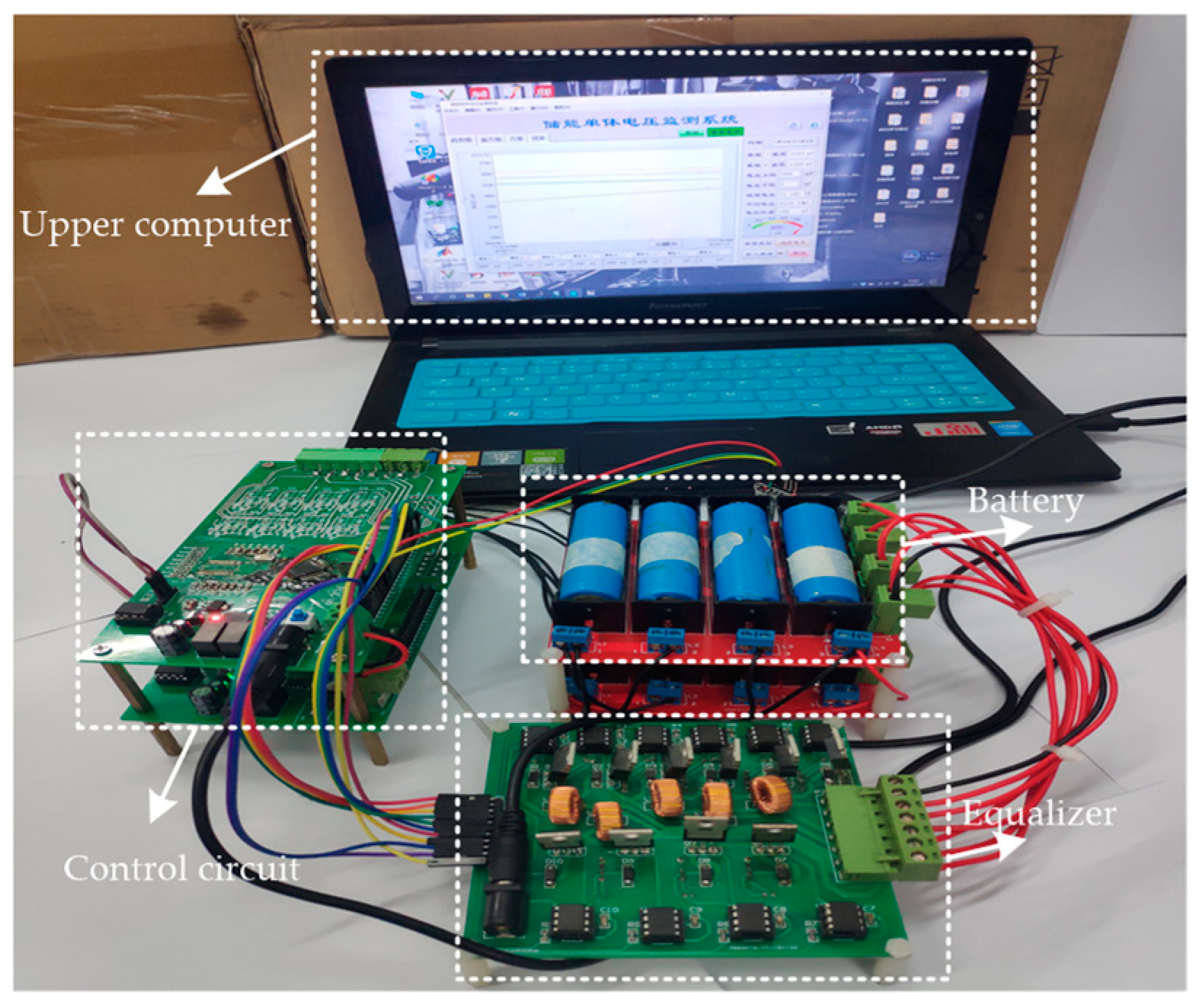
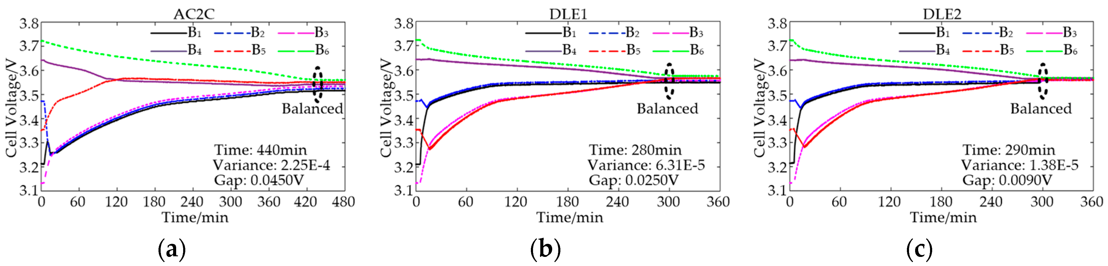
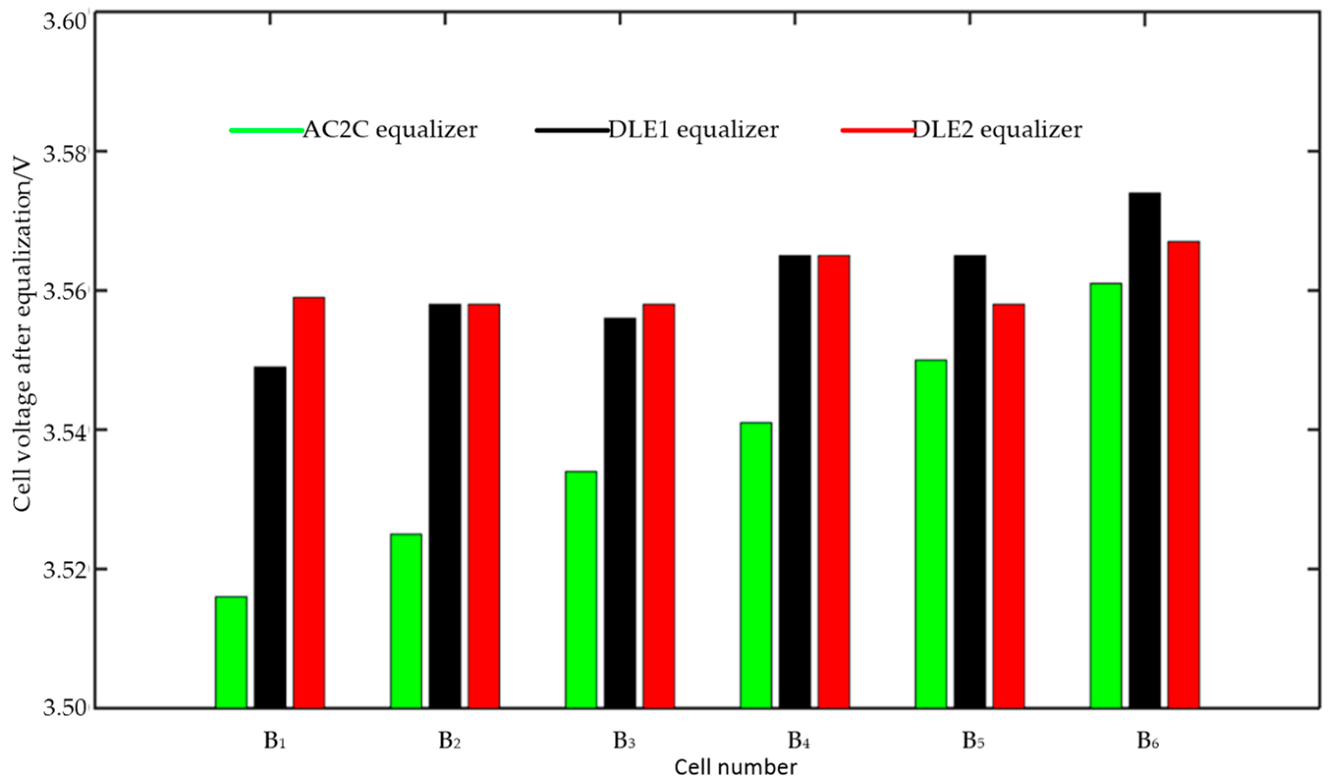
6. Experimental Results
7. Conclusions
Author Contributions
Funding
Conflicts of Interest
References
- Cassani, P.; Williamson, S. Significance of battery cell equalization and monitoring for practical commercialization of plug-in hybrid electric vehicles. In Proceedings of the 2009 Twenty-Fourth Annual IEEE Applied Power Electronics Conference and Exposition, Washington, DC, USA, 15–19 February 2009; pp. 4654–4671. [Google Scholar]
- Chan, C.; Chau, K. An overview of electric vehicles-challenges and opportunities. In Proceedings of the 22nd International Conference on Industrial Electronics, Control, and Instrumentation, Taipei, Taiwan, 9–9 August 1996; pp. 1–6. [Google Scholar]
- Cao, J.; Schofield, N.; Emadi, A. Battery balancing methods: A comprehensive review. In Proceedings of the 2008 IEEE Vehicle Power and Propulsion Conference, Harbin, China, 3–5 September 2008; pp. 1–6. [Google Scholar]
- Linzen, D.; Buller, S.; Karden, E.; Doncker, R.W.D. Analysis and evaluation of charge balancing circuits on performance, reliability and lifetime of supercapacitor systems. IEEE Trans. Ind. Appl. 2005, 41, 1135–1141. [Google Scholar] [CrossRef]
- Daowd, M.; Omar, N.; Bossche, P.V.D.; Mierlo, J.V. A review of passive and active battery balancing based on Matlab/Simulink. In Proceedings of the 2011 IEEE Vehicle Power and Propulsion Conference, Chicago, IL, USA, 6–9 September 2011; pp. 2974–2989. [Google Scholar]
- Lindemark, B. Individual cell voltage equalizers (ICE) for reliable battery performance. In Proceedings of the Thirteenth International Telecommunications Energy Conference-INTELEC 91, Kyoto, Japan, 5–8 November 1991; pp. 196–201. [Google Scholar]
- Pascual, C.; Krein, P. Switched capacitor system for automatic series battery equalization. In Proceedings of the Applied Power Electronics Conference, Atlanta, GA, USA, 27 February 1997; pp. 848–854. [Google Scholar]
- Ye, Y.; Cheng, K.W.E. An automatic switched-capacitor cell balancing circuit for series-connected battery string. Energies 2016, 9, 138. [Google Scholar] [CrossRef]
- Kim, M.; Kim, C.; Kim, J.; Moon, G. A chain structure of switched capacitor for improved cell balancing speed of lithium-ion batteries. IEEE Trans. Ind. Electron. 2014, 61, 3989–3999. [Google Scholar] [CrossRef]
- Kutkut, N.; Wiegman, H.; Divan, D.; Novotny, D. Design considerations for charge equalization of an electric vehicle battery system. IEEE Trans. Ind. Appl. 1999, 35, 28–35. [Google Scholar] [CrossRef]
- Cassani, P.A.; Williamson, S.S. Design, testing, and validation of a simplified control scheme for a novel plug-in hybrid electric vehicle battery cell equalizer. IEEE Trans. Ind. Electron. 2010, 57, 3956–3962. [Google Scholar] [CrossRef]
- Guo, X.; Kang, L.; Huang, Z.; Yao, Y.; Yang, H. Research on a novel power inductor-based bidirectional lossless equalization circuit for series-connected battery packs. Energies 2015, 8, 5555–5576. [Google Scholar] [CrossRef]
- Wang, S.; Kang, L.; Guo, X.; Wang, Z.; Liu, M. A novel layered bidirectional equalizer based on a buck-boost converter for series-connected battery strings. Energies 2017, 10, 1011. [Google Scholar] [CrossRef]
- Peng, F.; Wang, H.; Yu, L. Analysis and design considerations of efficiency enhanced hierarchical battery equalizer based on bipolar CCM buck-boost unit. IEEE Trans. Ind. Appl. 2019, 55, 4053–4063. [Google Scholar] [CrossRef]
- Kim, M.; Kim, J.; Moon, G. Center-cell concentration structure of a cell-to-cell balancing circuit with a reduced number of switches. IEEE Trans. Power Electron. 2014, 29, 5285–5297. [Google Scholar] [CrossRef]
- Dong, B.; Li, Y.; Han, Y. Parallel architecture for battery charge equalization. IEEE Trans. Power Electron. 2015, 30, 4906–4913. [Google Scholar] [CrossRef]
- Lee, K.; Lee, S.; Choi, Y.; Kang, B. Active balancing of Li-Ion battery cells using transformer as energy carrier. IEEE Trans. Ind. Electron. 2017, 64, 1251–1257. [Google Scholar] [CrossRef]
- Park, H.; Kim, J.; Kim, C.; Moon., G.; Lee, J. A modularized charge Equalizer for an HEV lithium-ion battery string. IEEE Trans. Ind. Electron. 2009, 56, 1464–1476. [Google Scholar] [CrossRef]
- Uno, M.; Kukita, A. String-to-battery voltage equalizer based on a half-bridge converter with multistacked current doublers for series-connected batteries. IEEE Trans. Power Electron. 2019, 34, 1286–1298. [Google Scholar] [CrossRef]


| i | Odd Number | Even Number | |
|---|---|---|---|
| Layer | |||
| Inner-layer | |||
| Outer-layer | |||
| i | Odd Number | Even Number | |
|---|---|---|---|
| j | |||
| Odd number | |||
| Even number | |||
| j | Odd Number | Even Number | |
|---|---|---|---|
| Layer | |||
| Inner-layer | |||
| B1 (V) | B2 (V) | B3 (V) | B4 (V) | B5 (V) | B6 (V) | |
|---|---|---|---|---|---|---|
| Case 1 | 3.21 | 3.47 | 3.35 | 3.72 | 3.13 | 3.64 |
| Case 2 | 3.21 | 3.47 | 3.13 | 3.64 | 3.35 | 3.72 |
| Case 3 | 3.35 | 3.72 | 3.21 | 3.47 | 3.13 | 3.64 |
| Case 4 | 3.35 | 3.72 | 3.13 | 3.64 | 3.21 | 3.47 |
| Case 5 | 3.13 | 3.64 | 3.21 | 3.47 | 3.35 | 3.72 |
| Case 6 | 3.13 | 3.64 | 3.35 | 3.72 | 3.21 | 3.47 |
| AC2C | DLE1 | DLE2 | |
|---|---|---|---|
| Equalization time (ms) | 90.67 | 85.42 | 88.97 |
| Variance | 2.3×10⁻⁴ | 8.16×10⁻⁵ | 2.17×10⁻⁵ |
| Voltage gap (V) | 0.0421 | 0.0267 | 0.0097 |
| Parameters | Value | |
|---|---|---|
| Cell balancing circuit | MOSFET | IRF540NPBF |
| Gate driver | HCPL-3120 | |
| Switching frequency | 10 KHz | |
| Inductor | 100 µH | |
| Microcontroller | STM32F103RCT6 | |
| Acquisition chip | LTC6803 | |
| Lithium-ion battery | Nominal capacity | 2 Ah |
| Cell voltage variation | 2.8–4.2 V | |
© 2019 by the authors. Licensee MDPI, Basel, Switzerland. This article is an open access article distributed under the terms and conditions of the Creative Commons Attribution (CC BY) license (http://creativecommons.org/licenses/by/4.0/).
Share and Cite
Xu, S.; Gao, K.; Zhang, X.; Li, K. Double-Layer E-Structure Equalization Circuit for Series Connected Battery Strings. Energies 2019, 12, 4252. https://doi.org/10.3390/en12224252
Xu S, Gao K, Zhang X, Li K. Double-Layer E-Structure Equalization Circuit for Series Connected Battery Strings. Energies. 2019; 12(22):4252. https://doi.org/10.3390/en12224252
Chicago/Turabian StyleXu, Shungang, Kai Gao, Xiaobing Zhang, and Kangle Li. 2019. "Double-Layer E-Structure Equalization Circuit for Series Connected Battery Strings" Energies 12, no. 22: 4252. https://doi.org/10.3390/en12224252
APA StyleXu, S., Gao, K., Zhang, X., & Li, K. (2019). Double-Layer E-Structure Equalization Circuit for Series Connected Battery Strings. Energies, 12(22), 4252. https://doi.org/10.3390/en12224252