Article

A New Control Strategy for Active Power Filter

1
Key Lab of Power Electronics for Energy Conservation and Motor Drive of Hebei province, College of Electrical Engineering Yanshan University, Qinhuangdao 066004, China
2
Department of Electrical and Computer Engineering, Curtin University, Perth, WA 6102, Australia
*
Author to whom correspondence should be addressed.
Energies 2019, 12(21), 4099; https://doi.org/10.3390/en12214099
Submission received: 27 September 2019 / Revised: 22 October 2019 / Accepted: 23 October 2019 / Published: 27 October 2019
(This article belongs to the Special Issue Active Power Filters)

Abstract

:
The significant increase in electronic devices has resulted in serious harmonic pollutions in electricity grids. In addition, due to the resonance of the system capacitance and inductance, the harmonic current may be amplified dramatically when it goes through the transmission line which is harmful to the normal operation of electrical equipment. To suppress the voltage and current harmonics resonance, many control strategies of active power filter (APF) are proposed. Nevertheless, these strategies cannot attenuate the amplified harmonic voltage and current due to resonance. In this paper, the harmonic propagation characteristics are investigated on a long transmission line and a new control strategy called VI-APF based on current-controlled and voltage-controlled current sources connected in parallel is presented. According to the simulation results, the proposed control strategy can suppress the total harmonic distortion to a low level. Finally, the effectiveness of VI-APF is demonstrated through the simulation on the IEEE 33-bus distribution system.

Graphical Abstract

1. Introduction

Recently, distributed generations (DGs) have gained popularity for increasing the reliability of distribution networks, and power quality has become a significant issue [1]. Due to the power electronics interfacing various DGs with the grid, voltage and current harmonics are increasing [2]. When high harmonic current orders flow through a long transmission line, the line distributed capacitance cannot be neglected and may resonate with the inductive components of the system causing significant distortion to the current and voltage waveforms, exacerbating harmonic pollution which has become an essential problem to be solved [3,4,5,6]. According to IEEE STD 519—2014, the harmonic voltage distortion rate limits are as shown in Table 1 [7].
Much literature reveals that the performance of electric devices is seriously affected when the total harmonic distortion (THD) is more than 20% [8,9]. To eliminate the effect of harmonic currents on the performance of a relay, a simple and reliable active filter design is introduced, but the transmission characteristic and resonance of harmonic currents are not considered in such a design [9,10]. Research [1] provides a method to solve the power quality of the source side and reduce the effects of harmonic components on rectifier transformer. In [11], a control strategy for active power filter (APF) is presented to suppress the harmonic voltage on long transmission lines under a no-load condition. As transmission system parameters may change with the load variation, the proposed APF may not have a good performance at all loading conditions due to its constant damping conductance. A discrete tuning active filter is proposed to suppress the harmonic voltage in which the damping conductance can be autonomously adjusted in response to the variation of the harmonic source and transmission line parameters, but harmonic current resonance is not considered in this technique [12]. In [13], a digital active power filter controller was proposed to only reduce the current distortion.
In this paper, a new control strategy for the active power filter is proposed to suppress resonance harmonics in long transmission lines and power systems. In Section 2, the propagation characteristics of harmonics on the transmission line are realized. In Section 3, the control strategy is analyzed, and the harmonic abstract part is introduced. Because the alternating current (AC) current generated by the three-phase bridge rectifier mainly includes 6k ± 1 harmonic orders, where k is an integer number, and the higher order harmonics will be of small amplitudes, this paper only considers the fifth and seventh harmonics. In Section 4, VI-APF exhibits better results in suppressing both harmonic voltage and current than a traditional control strategy in a 60 km transmission line simulation. Finally, the effectiveness of the proposed technique is illustrated through the IEEE 33-bus distribution system simulation analysis carried out using Matlab / Simulink software.

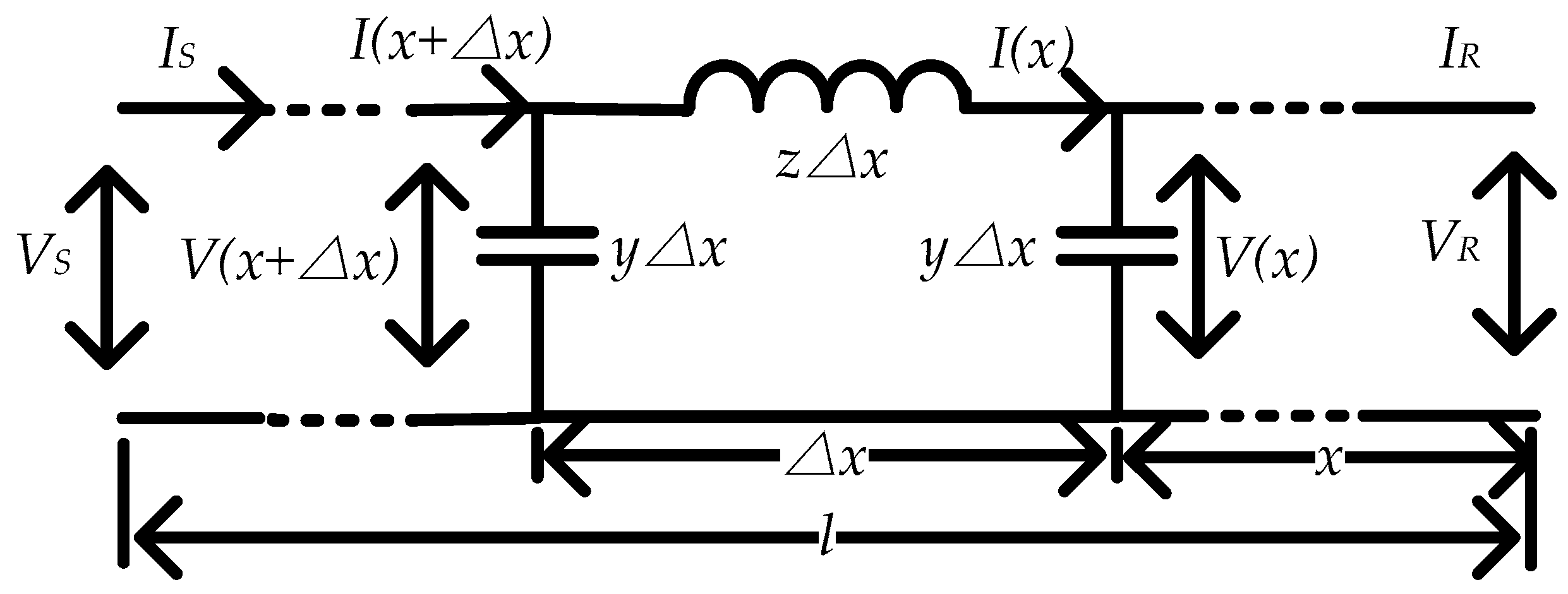
2. Transmission Line Model and Harmonics Characteristics

Figure 1 represents the R-L-C model of a long transmission line in which the sending end voltage (VS) and current (IS) can be correlated with the voltage and the current at any location on the transmission line (x, measured from the receiving end) using the following equation [14].
I ( x ) = I 1 + I 2 = cosh ( γ x ) V S sinh ( γ x ) Z C I S    
According to (1), the current flowing through the transmission line comprises of two components; I1 which is an incident wave from source side, and I2 which is a reflected wave from the load side. Due to superposition of the incident wave and the reflected wave, the harmonic current may be amplified at certain frequency and location. Therefore, it is necessary to develop a cost effective technique to suppress such harmonic resonace which is the main aim of this paper.

3. Analysis and VI-APF Control Strategy
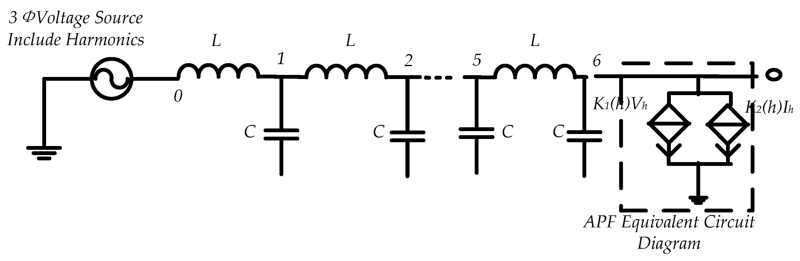
Harmonic current amplification on the transmission line is mainly due to resonance, during which the transmission line presents a low impedance to the harmonic current flow. In addition, during transient and fault events, the harmonic current results in travelling waves [15]. When the transmission line operates with no load or a light load, the harmonic travelling wave tends to reflect from the load side, which may result in harmonic amplification. Thus, this paper considers the line harmonic current attenuation during the light load condition.

3.1. VI-APF Model

Figure 2 shows a simplified three-phase transmission line with an APF installed at the receiving end. The three-phase voltage source mainly includes fifth and seventh harmonic orders, and the APF is represented by an equivalent current-controlled current source and a voltage-controlled current source. The control coefficients K1(h) and K2(h) are for the h harmonic order.
When the transmission line parameters and the harmonics voltage Vh and harmonic current Ih at node zero are known, the harmonic current at x km from the receiving end of the transmission line I(x) can be calculated from:
I h ( x ) = K 1 V h + K 2 I h = cosh ( γ x ) V h sinh ( γ x ) Z c I h
γ = ( R 0 + j ω L 0 ) ( G 0 + j ω C 0 ) = j ω L 0 C 0
where γ is the harmonic propagation coefficient, and Zc is the characteristic impedance of the transmission line.
As shown in Figure 2, the APF is installed at the end point of the line, and the APF current command i a b c * can be represented by:
i a b c * = i a b c h + h i a b c ( h ) = K u a b c h + h [ K 1 ( h ) u h + K 2 ( h ) i h ]
where i a b c h and uabch are the compensating harmonic current and voltage during the no resonance condition and iabc(h) is the compensating current for the amplified harmonics because of resonance. uh and ih are the amplified hth harmonic voltage and current because of resonance. The compensation coefficients K1(h) and K2(h) can be calculated as follows,
K = 1 / Z c                       K 1 ( h ) = cosh ( γ l )                               K 2 ( h ) = sinh ( γ l ) / Z c
where l is the length of the line.

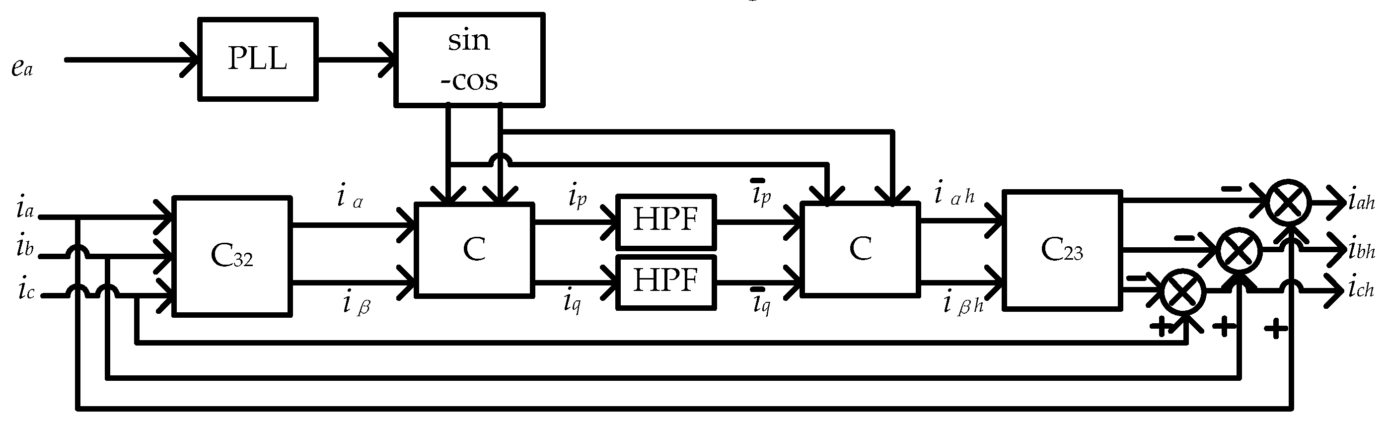
3.2. Harmonic Extraction

In this paper, instantaneous reactive power theory is used to detect and extract harmonics [16,17,18]. The method is based on Park’s and Clark’s transformations to obtain the three-phase harmonic currents, and the relevant calculation as shown in Figure 3 [19].
In Figure 3, the instantaneous values of the three-phase current ia, ib and ic are transformed into the (α-β) coordinate system using Park’s transformation, and the fundamental current component becomes a dc value. Then, the dc component can be filtered using a low-pass filter (LPF) as shown in Figure 3. Thus, the three-phase harmonic current component can be extracted by Clark’s transformation [20].
The two-phase instantaneous currents iα, iβ and ip, iq can be obtained as below [21,22].
C = [ sin ω t cos ω t cos ω t sin ω t ]
C 32 = C 23 T = 2 / 3 [ 1 1 / 2 1 / 2 0 3 / 2 3 / 2 ]
where ω is the power frequency in rad/s.

3.3. Proposed Control Strategy of VI-APF

The control strategy of VI-APF is shown in Figure 4. In this figure, the current command i a b c * is calculated using eabc, iabc and vabc, where eabc and iabc are the voltage and current at the start point of the transmission line, and vabc is the voltage at the APF installed point. eabc and iabc are used to obtain the current command for attenuating the amplified harmonics due to the resonance, and vabc is used to obtain the current command for suppressing other harmonic orders.
The total harmonic components of eabc and iabc can be obtained by Park’s transformation, the low-pass filter and Clark’s transformation of the fundamental frequency ω. Due to the different coefficients of various harmonic orders, the amplified harmonic current because of resonance and other harmonic components need to be derived from the total harmonic orders. Similarly, specific order harmonics can be selectively derived by Park’s transformation, the low-pass filter, and Clark’s transformation at harmonic frequency ωh. The cut-off frequency of the employed low-pass filters in this paper is set at 10Hz where ea and ia are the single-phase voltage and current measured at one end of the transmission line; e, e5, e7 and i, i5, i7 are used to obtain the fifth and seventh harmonic components that lag ea and ia by 2π·(1 − t/T+ ⌊t/T⌋) rad; and t is voltage-optic and optic-computer conversion time.
It is worth mentioning that measured AC harmonic signals can be conversed to the dq reference frame before at the point of measurement. The data transmission delay would not be a serious issue as the main aim is to damp the steady state harmonic propagation.
e a = E a sin ( ω t + φ 1 )                     i a = I a sin ( ω t + φ 2 ) e = E a sin [ ω t + φ 1 2 π ( 1 t / T + t / T ) ]                     i = i a sin [ ω t + φ 2 2 π ( 1 t / T + t / T ) ] e 5 = E a sin [ 5 ω t + φ 1 2 π ( 1 t / T + t / T ) ]                     e 7 = E a sin [ 7 ω t + φ 1 2 π ( 1 t / T + t / T ) ] i 5 = i a sin [ 5 ω t + φ 2 2 π ( 1 t / T + t / T ) ]                     i 7 = i a sin [ 7 ω t + φ 2 2 π ( 1 t / T + t / T ) ]
where ea and ia are the single-phase voltage and current measured at one end of the transmission line; e, e5, e7 and i, i5, i7 are used to obtain the fifth and seventh harmonic components that lag ea and ia by 2π·(1 − t/T+ ⌊t/T⌋) rad; t is voltage-optic and optic-computer conversion time.

4. Simulation Results and Discussion

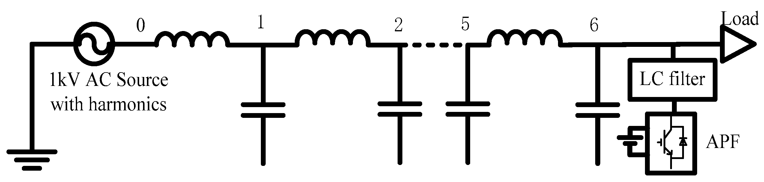
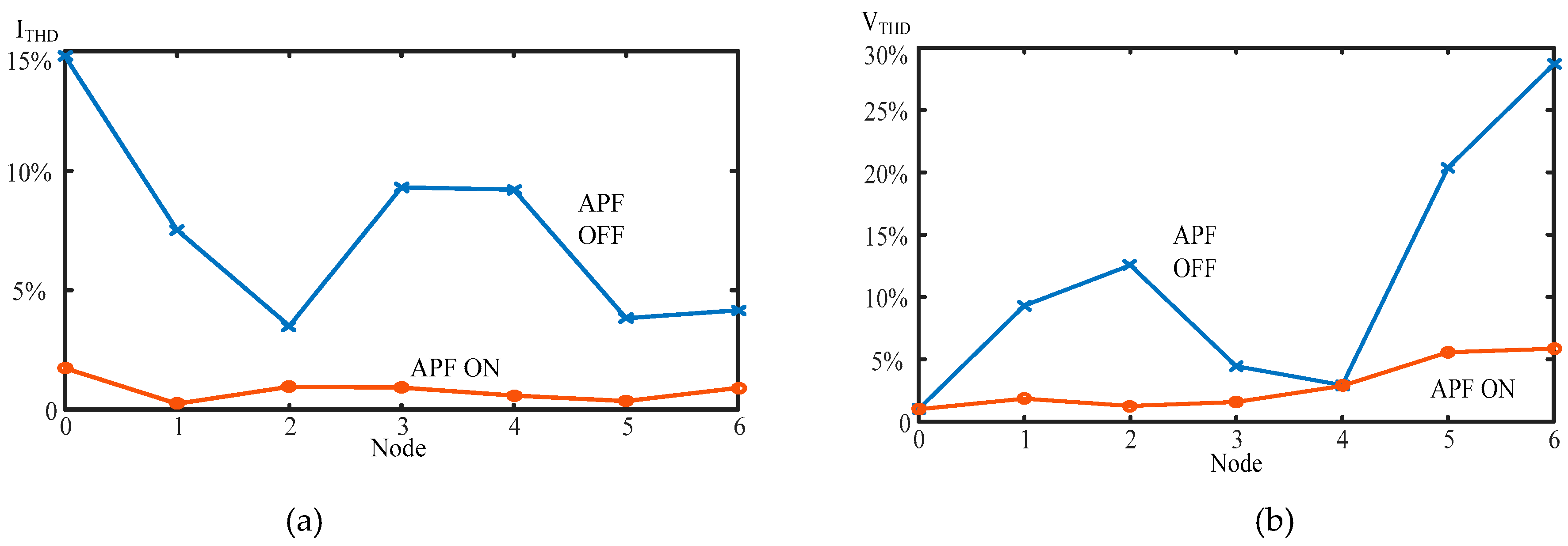
4.1. Case 1 Transmission Line System Simulation

The VI-APF control strategy was assessed through its application on a 60 km transmission line shown in Figure 5 with the parameters of the transmission line as listed in Table 2 [23,24].
The system voltage was 1kV including the fifth harmonic and seventh harmonic. Considering fifth and seventh harmonics amplification because of resonance; the coefficients K, K1(5), K1(7), K2(5), K2(7) can be calculated using (5) as follows:
K = 6.32 ,   K 1 ( 5 ) = 0.9976   ,   K 1 ( 7 ) = 0.9652 ,   K 2 ( 5 ) = j 4.927 × 10 3 ,   K 2 ( 7 ) = j 6.898 × 10 3
The 60-km transmission line was divided into six, 10-km sections from node zero to node six as shown in Figure 5. The APF was installed at node six, and an LC filter was connected with the APF to suppress the high frequency harmonic components due to the APF itself.

4.1.1. Fifth Harmonic Suppression

At first, the voltage of the fifth harmonic at node one was set at 40 V so that the voltage THD, VTHD was 4%. Figure 6 shows the magnitude of the current and voltage THD (ITHD, VTHD) at all the nodes. Figure 6a reveals that when VI-APF was connected, the magnitude of ITHD at all nodes except node zero and node five was significantly reduced. The THD at nodes zero and five was less than 2% with APF. Although ITHD at node zero was 0.44% when the APF was off, it was magnified by nearly 10 times at node two (ITHD = 4.28%), while the fifth harmonic current was not amplified when the APF was on. In Figure 6b, VTHD at node six was around 10% when the APF was off; exceeding the limits of the IEEE STD 519—2014 harmonic standard. When the APF was on, VTHD at all nodes it was reduced to a level less than 6%.

4.1.2. Seventh Harmonic Suppression

Similarly, the amplitude of the seventh harmonic voltage at node zero was set at 10V so that VTHD was 1%. As shown in Figure 7, the magnitude of the seventh harmonic current reached a peak THD value at node one of about 15%, and it reaches nearly 10% at node three and node four when the APF was off. On the other hand, although the voltage THD at node zero was only 1%, the value reached 28% at node six without the connection of the APF. When the APF was connected, ITHD at all nodes was reduced to a level less than 3%, and the maximum VTHD at node six, was significantly reduced to a level less than 6%.
The above results revealed the effectiveness of the VI-APF control strategy in suppressing and attenuating the fifth and seventh harmonic orders in both current and voltage waveforms.

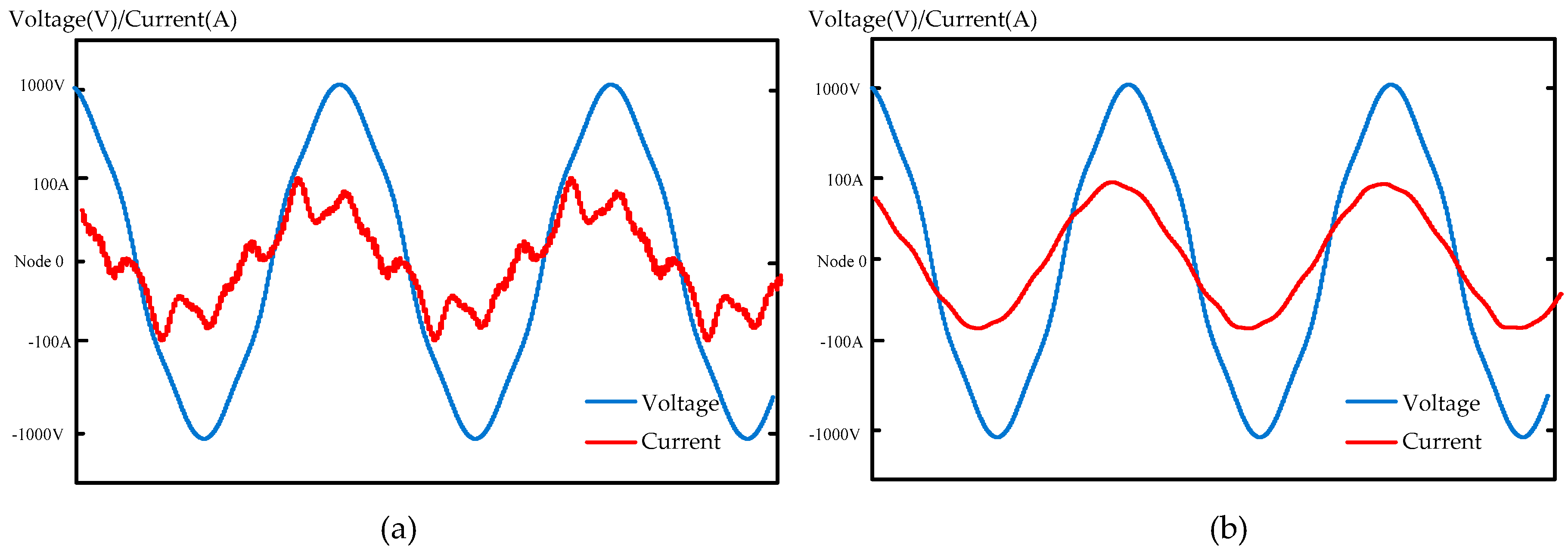
4.1.3. Nonlinear Load with Fifth and Seventh Harmonics

In this simulation, the harmonic suppression performance of a traditional APF called R-APF and VI-APF were compared, and the simulation results are shown in Figure 8, Figure 9, Figure 10, Figure 11, Figure 12 and Figure 13.
Figure 8 shows the THD based on the existence of both harmonic orders, fifth and seventh with the same voltage amplitudes in the above case studies. In addition, a nonlinear load was connected at node six. The harmonic components generated by the nonlinear load is as shown in Table 3. Figure 9 and Figure 10 are voltage and current waveforms, and are provided to clarify the improvement of the current and voltage waveforms. Figure 11 and Figure 12 are the current and voltage at node zero and node six when VI-APF is used. Figure 13 is voltage and current waveforms when the traditional R-APF is used.
When the APF was off, the ITHD at node zero reached a level higher than 30%, while VTHD reached a maximum value of 28% at node six as shown in Figure 8. When the APF was connected, VTHD and ITHD were all reduced. As for voltage, VI APF and R-APF both reduced the THD to a level less than 6%, but R-APF suppressed the harmonic current to a low level, for instance, ITHD reached 11% at several nodes as shown in Figure 13. With the connection of VI-APF, ITHD was reduced to a level less than 5%. It was obvious that VI-APF had a better performance in harmonic suppression than traditional R-APF.

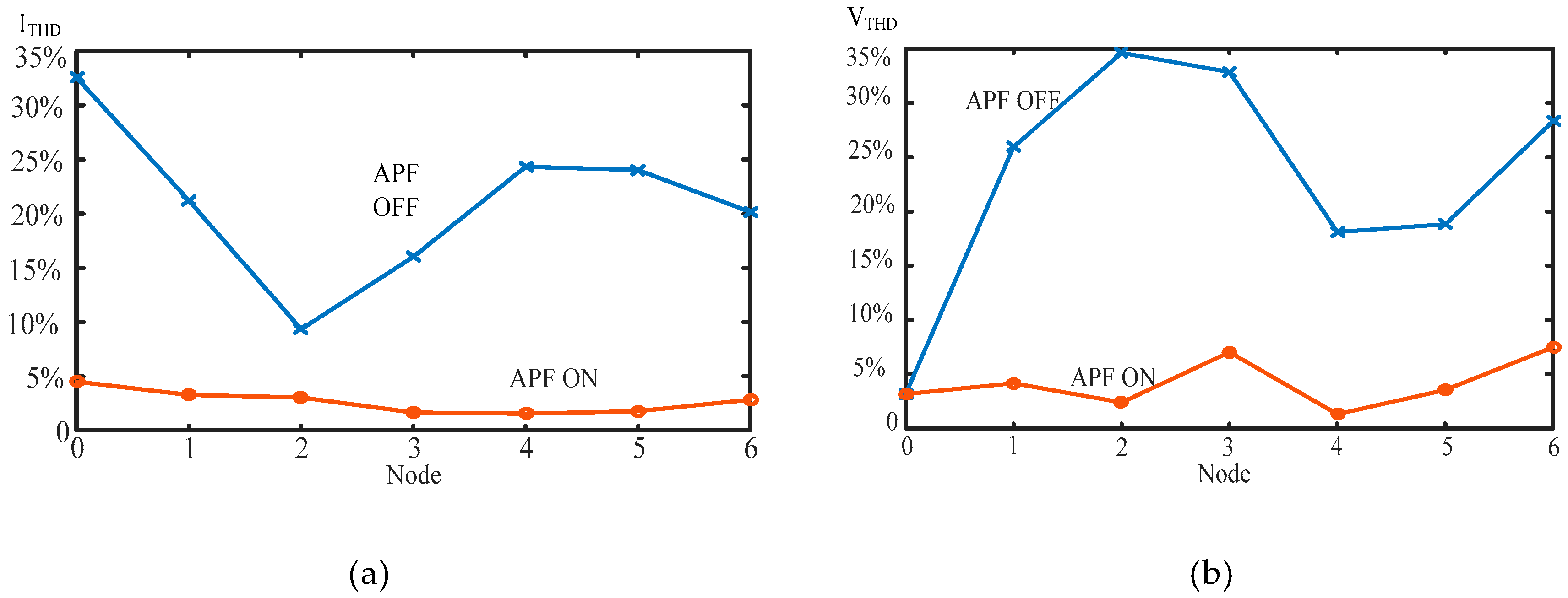
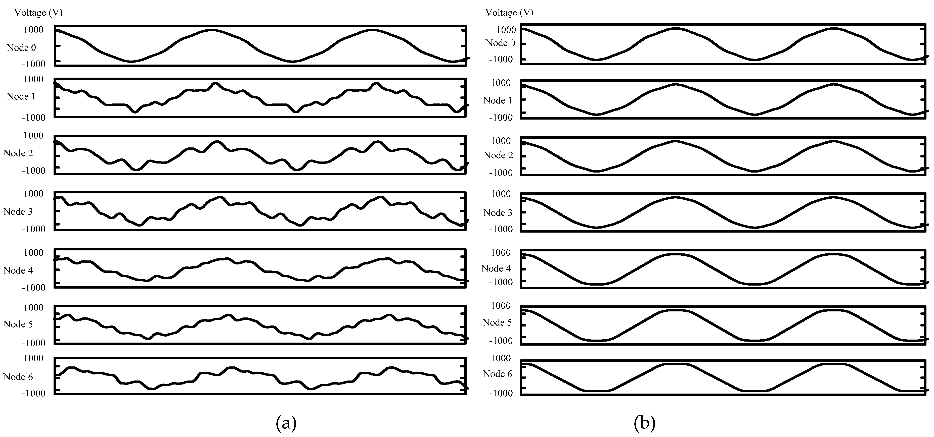
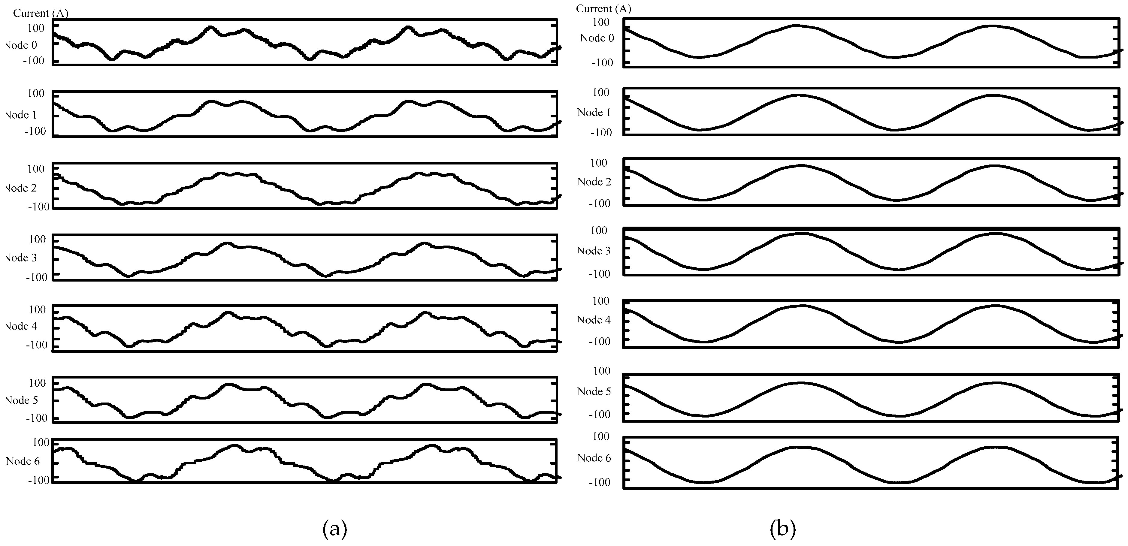
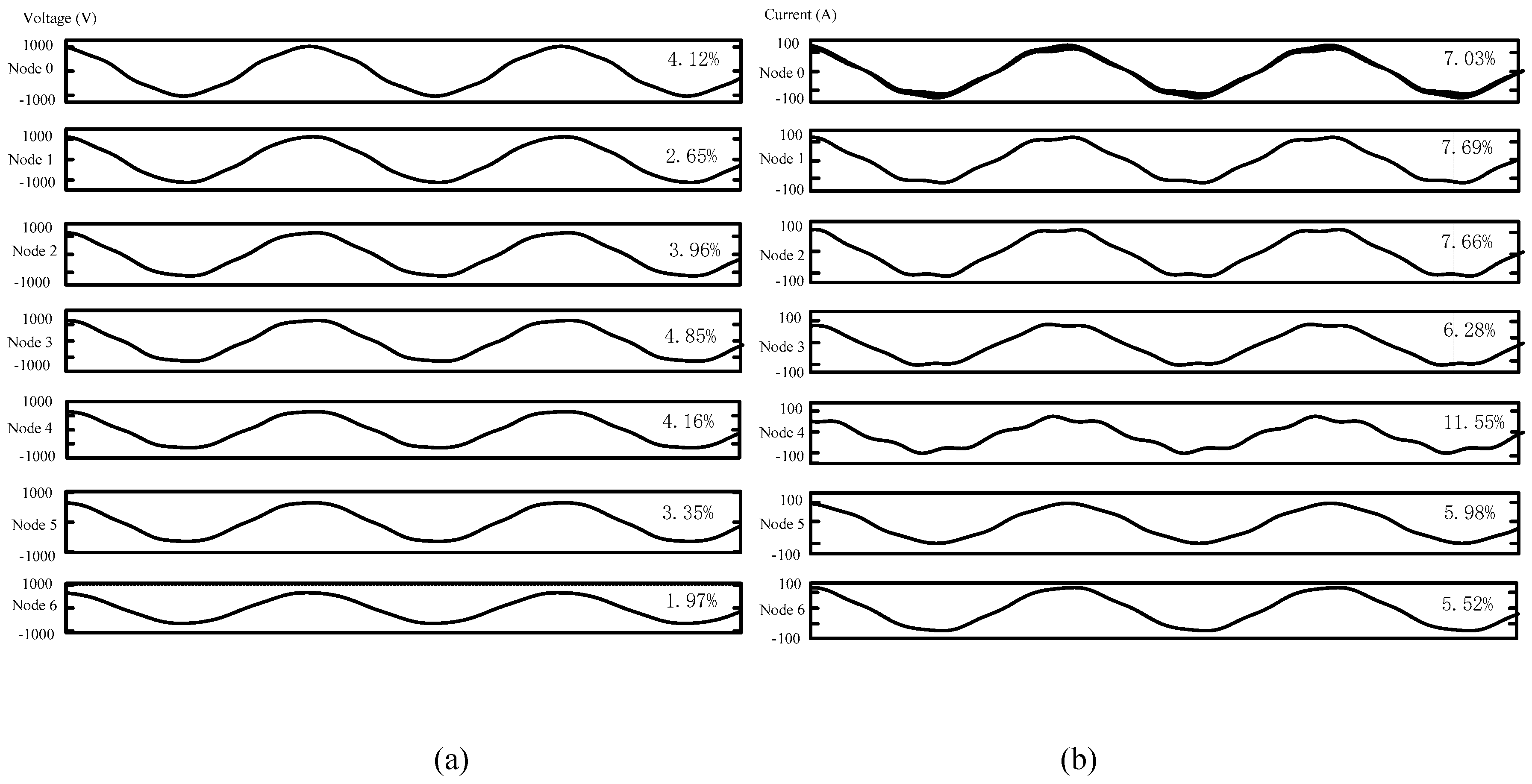
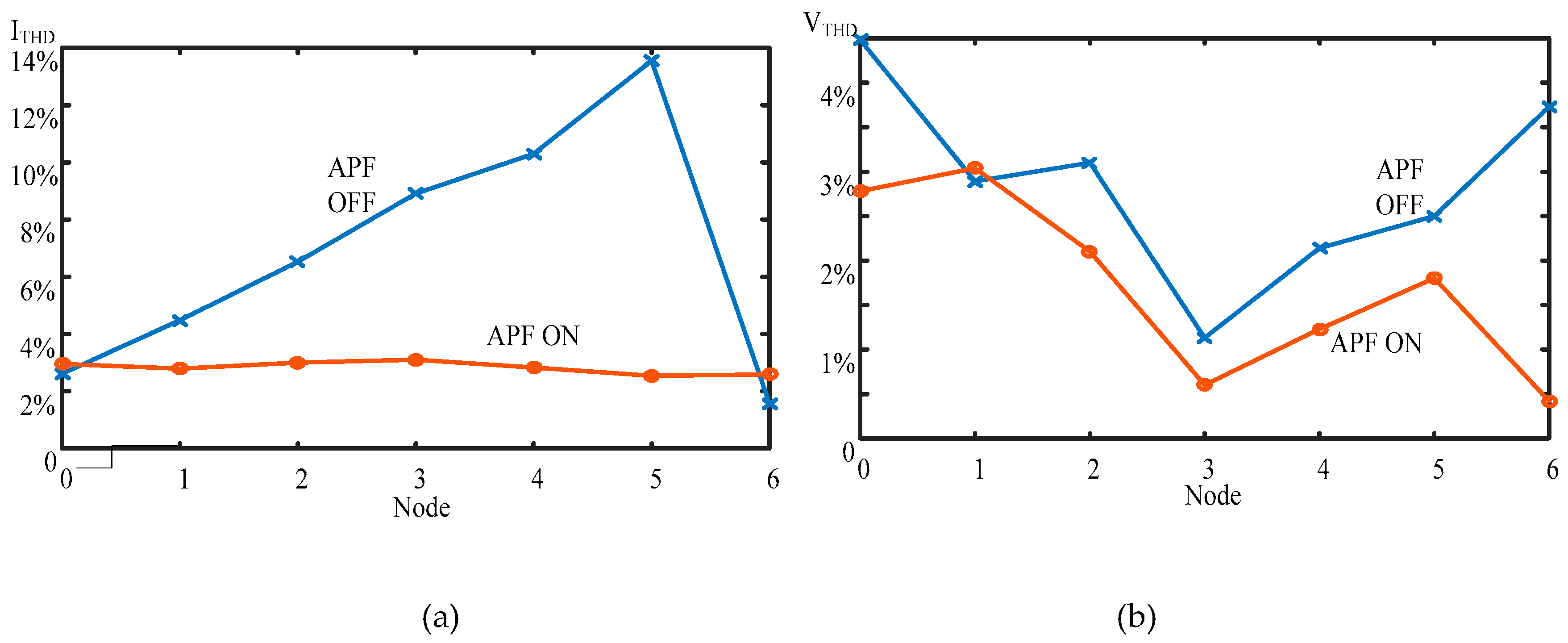
4.2. IEEE 33-Bus System Simulation

To investigate the robustness of VI-APF on harmonics suppression in a large distribution system, the IEEE 33-bus system shown in Figure 14 was simulated using Matlab/Simulink, with a 60km length transmission line connecting each adjacent node [25]. A nonlinear load was connected at bus 17 to inject harmonic components as listed in Table 3.
Simulation results show that VTHD and ITHD at bus 17 (ITHD = 2.61%, VTHD = 4.48%) and at bus 18 (ITHD = 2.59% VTHD = 4.75%) were higher than other buses when the APF was off. The THD at other buses was less than 1%. Therefore, the harmonic amplification characteristic on the transmission line between bus 17 and bus 18 should be investigated. In this context, the 60 km-line between bus 17 and bus 18 was divided into six 10-km sections from node zero to node six.
From Figure 15, it was observed that VTHD was less than 6% with and without the connection of the APF. However, if VI-APF was connected, the magnitude of VTHD at most nodes decreased. Additionally, when the APF was off, ITHD at node five was nearly 14%, exceeding the IEEE STD 519—2014 harmonic standard. With the connection of the APF, ITHD at all nodes was reduced to a level less than 5% that complied with IEEE standards.

5. Conclusions

In order to control harmonic pollution, a new APF control strategy was proposed to effectively suppress harmonic voltage and current components in power systems in this paper. Simulation results showed that, even if the magnitude of THD at the harmonic source was within the standards, it may exceed the standard at other nodes due to harmonic resonance within the transmission lines. In contrary to existing APF control strategies (R-APF), the proposed control strategy in this paper can effectively suppress and attenuate voltage and current harmonics of different orders and hence improve a system’s power quality. VI-APF can suppress the magnified harmonic currents due to resonance in radial transmission lines and a large distribution system and it is easy to implement in active power filters.

Author Contributions

Methodology and Formal Analysis, H.S. and F.Y.; Investigation, H.S., F.Y. and A.A.-S.; Writing-Original Draft Preparation, F.Y. and A.A.-S.; Writing-Review & Editing, F.Y. and H.S.; Visualization, H.S. and Z.L.; Supervision, H.S. and A.A.-S.; Funding Acquisition, H.S.

Funding

The research was funded by National Natural Science Foundation of China, grant number 51407155 and the APC was funded by Yanshan University.

Conflicts of Interest

The authors declare no conflict of interest.

References

  1. Zhenhua, L.; Tinghe, H.; Ahmed, A.-S. A minimum side-lobe optimization window function and its application in harmonic detection of an electricity gird. Energies 2019, 12, 2619. [Google Scholar]
  2. Zeng, Q.; Chang, L. An advanced SVPWM-based predictive current controller for three-phase inverters in distributed generation systems. IEEE Trans. Ind. Electron. 2008, 55, 1235–1246. [Google Scholar] [CrossRef]
  3. Shao, Z.; Shuai, J.; Xi, L.; Ge, B.; Fang, Z.P. Resonance issues and damping techniques for grid-connected inverters with long transmission cable. IEEE Trans. Power Electron. 2013, 29, 110–120. [Google Scholar]
  4. Lee, Y.D.; Chen, C.S.; Hsu, C.T.; Cheng, H.S. Harmonic analysis for the distribution system with dispersed generation systems. In Proceedings of the International Conference on Power System Technology, Chongqing, China, 22–26 October 2006. [Google Scholar]
  5. Abdou, A.F.; Abu-Siada, A.; Pota, H.R. Application of a STATCOM for damping subsynchronous oscillations and transient stability improvement. In Proceedings of the AUPEC, Brisbane, QLD, Australia, 25–28 September 2011; IEEE: Hoboken, NJ, USA, 2011; pp. 1–5. [Google Scholar]
  6. Abu-Siada, A.; Keerthipala, W.W.L. Effect of system parameters on harmonic levels in AC/DC systems. In Proceedings of the IPEC 2003—6th International Power Engineering Conference, Singapore, 27–29 November 2003; pp. 167–172. [Google Scholar]
  7. Dartawan, K.; Najafabadi, A.M. Case study: Applying IEEE Std. 519-2014 for harmonic distortion analysis of a 180 MW solar farm. In Proceedings of the IEEE Power & Energy Society General Meeting, Portland, OR, USA, 5–9 August 2018. [Google Scholar]
  8. Tin, H.; Abu-Siada, A.; Masoum, M.S. Power system harmonic mitigation using hybrid filters. In Proceedings of the 22nd Australasian Universities Power Engineering Conference, Bali, Indonesia, 26–29 September 2012; pp. 1–7. [Google Scholar]
  9. Abu-Siada, A. A novel design for adaptive harmonic filter to improve the performance of over current relays. Int. J. Adv. Eng. Technol. 2011, 1, 89–95. [Google Scholar]
  10. Tin, H.; Abu-Siada, A.; Masoum, M.S. Impact of harmonics on the performance of over-current relays. In Proceedings of the AUPEC, Brisbane, QLD, Australia, 25–28 September 2011; IEEE: Hoboken, NJ, USA, 2011; pp. 1–4. [Google Scholar]
  11. Wada, K.; Fujita, H.; Akagi, H. Considerations of a shunt active filter based on voltage detection for installation on a long distribution feeder. Ind. Appl. IEEE Trans. 2002, 38, 1123–1130. [Google Scholar] [CrossRef]
  12. Lee, T.L.; Li, J.C.; Cheng, P.T. Discrete frequency tuning active filter for power system harmonics. IEEE Trans. Power Electron. 2009, 24, 1209–1217. [Google Scholar]
  13. Ram, S.K.; Das, B.B. Digital controller design for three phase active power filter for harmonic and reactive power compensation using FPGA and system generator. In Proceedings of the International Conference on Inventive Computation Technologies, Coimbatore, India, 24–25 August 2017. [Google Scholar]
  14. Das, J.C. Power system analysis. In Short-Circuit Load Flow and Harmonics, 2nd ed.; Marcel Dekker, Inc.: New York, NY, USA, 2017. [Google Scholar]
  15. Sun, X.; Lee, Z.; Gong, L.; Chen, Z. A novel control strategy of active filter for suppressing background harmonic voltage magnification in power distribution system. In Proceedings of the Power Electronics & Motion Control Conference, Harbin, China, 2–5 June 2012. [Google Scholar]
  16. Dai, W.; Yu, W. A novel three-phase active power filter based on instantaneous reactive power theory. In Proceedings of the Workshop on Power Electronics & Intelligent Transportation System, Guangzhou, China, 2–3 August 2008. [Google Scholar]
  17. Chamat, N.M.; Bhandare, V.S.; Diwan, S.P.; Jamadade, S. Instantaneous reactive power theory for real time control of three-phase shunt Active Power Filter (SAPF). In Proceedings of the International Conference on Circuit, Nagercoil, India, 19–20 March 2015. [Google Scholar]
  18. Marcu, M.; Popescu, F.G.; Niculescu, T.; Pana, L.; Handra, A.D. Simulation of power active filter using instantaneous reactive power theory. In Proceedings of the 2014 16th International Conference on Harmonics and Quality of Power (ICHQP), Bucharest, Romania, 25–28 May 2014. [Google Scholar]
  19. Tan, P.C.; Loh, P.C.; Holmes, D.G. High-performance harmonic extraction algorithm for a 25 kV traction power quality conditioner. IEE Electr. Power Appl. 2004, 151, 505–512. [Google Scholar] [CrossRef]
  20. Fujita, H.; Akagi, H.; Akagi, H. The unified power quality conditioner: The integration of series and shunt-active filters. In Proceedings of the IEEE Power Electronics Specialists Conference, Baveno, Italy, 23–27 June 1996. [Google Scholar]
  21. Ghosh, A.; Ledwich, G. A unified power quality conditioner (UPQC) for simultaneous voltage and current compensation. Electr. Power Syst. Res. 2001, 59, 55–63. [Google Scholar] [CrossRef]
  22. Gu, J.; Xu, D.; Liu, H.; Gong, M. Unified power quality conditioner (UPQC): The principle, control and application. In Proceedings of the Power Conversion Conference, Osaka, Japan, 2–5 April 2002. [Google Scholar]
  23. Flourentzou, N.; Agelidis, V.G.; Demetriades, G.D. VSC-based HVDC power transmission systems: An overview. IEEE Trans. Power Electron. 2009, 24, 592–602. [Google Scholar] [CrossRef]
  24. Chinchilla, M.; Arnaltes, S.; Burgos, J.C. Control of permanent-magnet generators applied to variable-speed wind-energy systems connected to the grid. IEEE Trans. Energy Convers. 2006, 21, 130–135. [Google Scholar] [CrossRef]
  25. Dharageshwari, K.; Nayanatara, C. Multiobjective optimal placement of multiple distributed generations in IEEE 33 bus radial system using simulated annealing. In Proceedings of the International Conference on Circuit, Nagercoil, India, 19–20 March 2015. [Google Scholar]
Figure 1. Long transmission line model.
Energies 12 04099 g001
Figure 2. Transmission system model and equivalent active power filter (APF).
Energies 12 04099 g002
Figure 3. ip-iq calculation.
Energies 12 04099 g003
Figure 4. VI-APF control strategy.
Energies 12 04099 g004
Figure 5. Simulation system.
Energies 12 04099 g005
Figure 6. THD of the fifth harmonic: (a) current, and (b) voltage.
Energies 12 04099 g006
Figure 7. Total harmonic distortion (THD) of seventh harmonic (a) current and (b) voltage.
Energies 12 04099 g007
Figure 8. THD with nonlinear load and background harmonic: (a) current, and (b)voltage.
Energies 12 04099 g008
Figure 9. Voltage waveform with nonlinear load and background harmonic: (a)VI-APF off, and (b)VI-APF on.
Energies 12 04099 g009
Figure 10. Current waveform with nonlinear load and background harmonic: (a) VI-APF off, and (b) VI-APF on.
Energies 12 04099 g010
Figure 11. Voltage and Current at node zero: (a)VI-APF off, and (b)VI-APF on.
Energies 12 04099 g011
Figure 12. Voltage and current at node six: (a)VI-APF off, and (b)VI-APF on.
Energies 12 04099 g012
Figure 13. Voltage and current waveform with traditional R-APF: (a) voltage, and (b) current.
Energies 12 04099 g013
Figure 14. The IEEE-33 bus distribution system.
Energies 12 04099 g014
Figure 15. THD at nodes between bus 17 and bus 18 of the IEEE 33-bus distribution system: (a) current, and (b) voltage.
Energies 12 04099 g015
Table 1. IEEE STD 519—2014 harmonic voltage distortion limit.
Bus VoltageSingle Harmonic Distortion (%)Total Harmonic Distortion (%)
U ≤ 1.0 kV5.08.0
1 Kv ˂ U ≤ 69 kV3.05.0
69 kV ˂ U ≤ 161 kV1.52.5
Table 2. Transmission System Parameters.
System ratingsValue
System frequency50 Hz
Source Voltage1 kV
Fifth Harmonic Voltage10 V
Seventh Harmonic Voltage10 V
Load10 kW
Transmission line length60 km
Line inductance per km0.6 mH
Line capacitance per km15 μF
Inductance of LC filter (L)2 mH
Capacitance of LC filter (C)30 µF
Table 3. Harmonic components of the nonlinear load.
Harmonic order2357
Voltage THD (VTHD)0.3%1.70%1.41%1.01%

