Article

Numerical Investigation of Liquid Water Transport Dynamics in Novel Hybrid Sinusoidal Flow Channel Designs for PEMFC

1
State Key Laboratory of Engines, Tianjin University, 135 Yaguan Road, Tianjin 300350, China
2
Weichai Power Co. Ltd., 197A Fushou St. E., Weifang 261016, China
3
Department of Chemical Engineering, Loughborough University, Loughborough, UK
*
Authors to whom correspondence should be addressed.
Energies 2019, 12(21), 4030; https://doi.org/10.3390/en12214030
Submission received: 16 September 2019 / Revised: 16 October 2019 / Accepted: 22 October 2019 / Published: 23 October 2019
(This article belongs to the Section A5: Hydrogen Energy)

Abstract

:
This study numerically investigates liquid water dynamics in a novel hybrid sinusoidal flow channel of a proton exchange membrane fuel cell (PEMFC). The two-phase flow is examined using a three-dimensional, transient computational fluid dynamics (CFD) simulation employing the coupled level set and volume of fluid (VOF) method. Simulations for hybrid and non-hybrid sinusoidal flow channels, including a straight flow channel, are compared based on their water exhaust capacities and pressure drops. Additionally, the effects of inlet gas velocity, wall wettability, and droplet interaction in the flow channel on the dynamic behaviour of liquid water are investigated. Results reveal that the novel hybrid sinusoidal channel designs are consistent in terms of quicker water removal under varying hydrophilic wall conditions. Also, it is found that the liquid surface coverage, detachment, and removal rate depends on droplet proximity to the walls, inlet gas velocity, and wall contact angle. Also, the time a droplet makes contact with the side walls affect the discharge time. Additionally, there is an improvement in the gas velocity magnitude and vertical component velocity across the hybrid sinusoidal channel designs. Therefore, the unique geometric configuration of the proposed hybrid design makes it a viable substitute for water management in PEMFC applications.

Graphical Abstract

1. Introduction

In recent times, the sinusoidal (wavy) channel has been reported to be a passive method of improving heat transfer characteristics [1]. These undulating flow passages are commonly applied in fluid transportation, heat exchange, and thermal power generation [2,3]. However, in proton exchange membrane fuel cell (PEMFC) applications, this wavy architecture has not received much attention irrespective of the outstanding advantages they offer. Consequently, the sinusoidal flow channel has been reported to significantly enhance heat/mass transfer, especially in compact exchange devices [4,5]. Also, some authors have reported the idea of using this wavy configuration as a substitute to the conventional rectangular microchannel and as a means of enhancing heat transfer performance [2,6]. Despite the significantly improved heat transfer performance peculiar to these configurations, the pressure drop increase is one of the inherent penalties [1].
Additionally, they offer positive characteristics, such as significant heat transfer coefficients, low coolant requirements, small size, and high surface area-to-volume [7]. As such, wavy architecture can be very useful in this regime and our aim, therefore, has been to quantify these gains as well as demerits (slight pressure drop increase) through detailed numerical computations of the two-phase transient flow. The unique nature of wavy channels allows for secondary flow inducements across the channel, which ultimately benefits two-phase flows. This positive behaviour would significantly enhance PEMFC performance via efficient water management and improved mass transport. So far, the improvement in PEMFC performance has been reported both experimentally and numerically in cases where the wavy flow channels were employed [8,9].
Consequently, flow channel optimisation remains one of the fundamental techniques for efficient water management in PEMFC channels [10], since channel geometry significantly influences the reactant utilisation efficiency and transport, water management, and ultimately, overall cell performance [11]. Therefore, channel design is a critical issue in PEMFC development, and care must be taken to manage the liquid water generated to prevent component damage or performance degradation [12]. During the electrochemical reaction, over-accumulation of liquid water can lead to flooding, especially at the cathode side, and this condition adversely affects reactant transport. While humidification within the PEMFC plays a vital role to prevent membrane dehydration, there is a trade-off between water management and cell performance. As such, channel design remains an essential consideration in water management and overall PEMFC performance. The continuing research into the modelling of water transport in PEMFCs provides a basis on which novel channel design demonstrates the inherent poor water management performance of conventional (straight) channels.
Researchers have investigated water transportation in the microchannels of PEMFCs and have studied methods of preventing flooding such as flow channel design modification. Performance in channels of different geometries has been experimentally studied [13,14]. However, the lack of an experimental technique in the study of fluid flow in channels remains a challenge for PEMFC systems. Therefore, employing the volume of fluid (VOF) method in the computational fluid dynamics framework has furnished much insight into two-phase flow dynamics in microchannels [15]. Anderson et al. [16] verified the VOF model for a PEMFC gas channel using synchrotron measurements. There was an excellent agreement with their model and the measurements concerning droplet dynamics, shape, and size. Niu et al. [17] experimentally validated a three-dimensional (3D) two-phase VOF numerical model, which they used to investigate the dynamic water behaviour in two innovative PEMFC flow channels. Their results suggested that the proposed designs could improve PEMFC performance depending on the operating conditions. Li et al. [18] investigated the dynamic behaviour of the moving liquid column coalescing with a sessile droplet in a hydrophilic microchannel using the VOF methodology along with the continuum surface force (CSF) model. They opined that droplet coalescence promotes liquid movement and the larger the droplet size, the faster its acceleration. Jo and Kim [19] also analysed the dynamics of liquid water emerging from a gas diffusion layer pore into a right-angle microchannel of a proton exchange membrane fuel cell using the VOF method. They reported the significance of channel configuration, the coverage ratio of water on the gas diffusion layer (GDL) surface, and the water volume fraction on cell performance. Shen et al. [20] employed a transient 3D model based on the VOF methodology to evaluate the dynamic behaviour of gas–liquid two-phase flow in a PEMFC microchannel. They assessed the effect of channel structure, the contact angle of channel walls, inlet velocity, droplet size effect, and the phase transition effect in a straight channel. Their results proved that channel surface contact angle had a tremendous impact on droplet transport. Kim and Kim [21] also numerically studied the liquid water dynamics in rectangular and trapezoidal microchannels using the VOF technique. The effect of the top and side walls static contact angle and the air inlet velocity was studied based on water removal characteristics. Their investigative study showed the significance of channel geometry on water expulsion in channels. Recently, Xu et al. [22] investigated the dynamics of droplet emergence and removal in a wavelike flow channel through computational fluid dynamics (CFD) simulation in association with the VOF method. The effects of contact angle and geometric parameters were also considered in their work.
Analysis of two-phase flow in microchannels using the level-set (LS) method has also been conducted by a few researchers [23,24]. Mukherjee and Kandlikar [23] numerically used the LS technique to evaluate liquid water evolution and detachment in a channel. Also, Akhtar and Kerkhof [24] employed the LS method to assess the effect of wall property on liquid water dynamics in a tapered channel. However, coupling the LS method and the VOF method as reported by some researchers proves to be much superior compared to the standalone LS or VOF method [25,26]. As such, Sussman and Puckett [25] presented a coupled LS and VOF (CLSVOF) method that highlighted the mutual benefits of the VOF and LS methods. They gave a detailed insight into the accuracy and stability of the CLSVOF method compared to the VOF or LS methods independently. Three-dimensional calculations have also been conducted to investigate the rising of a bubble in the quiescent water and at equilibrium using the CLSVOF method by Tsui et al. [26].
In light of this, while existing sinusoidal flow channel designs appear to have just one repeating pitch arrangement, it will be beneficial to combine dual pitches and amplitudes to design a hybrid sinusoidal flow channel. As stated earlier, the high-pressure drop is one major disadvantage associated with the sinusoidal flow channel designs. However, in the existing literature, the channel pitch and amplitude arrangement are often homogeneous, having one repeating pitch arrangement with no flexibility. The hybrid sinusoidal design which combines dual-channel pitches and amplitudes would offer improved flow performance, with a slightly higher pressure drop compared to the straight channel design. As such, the architecture enables interconnectivity between the pitches and amplitudes. One of the significant benefits in addition to the ability to integrate different pitch sizes is the ability also to vary the bend radiuses and amplitudes. This would provide designers and operators with a flexible flow system that can adjust to changing needs and requirements depending on operating conditions. Consequently, when developing a hybrid sinusoidal flow channel, the options become limitless because the designer’s choice affects the flow characteristics and overall performance.
Therefore, motivated by our previous research [27], we propose a novel hybrid sinusoidal gas flow channel in this study. CFD simulations with a three-dimensional VOF model coupled with LS function is implemented using ANSYS Fluent (17.2, ANSYS Inc.: Canonsburg, PA, USA) in evaluating the liquid water expulsion rate in the proposed novel flow channel designs. Additionally, the effects of wall contact angle, channel amplitude, and gas feed velocity are also investigated. The findings presented in this paper could further expand the possibilities of adopting the hybrid sinusoidal channel as a better alternative to the conventional channel with regards to PEMFC overall performance.
This paper is structurally arranged as follows. In Section 2, the numerical formulation employed is described. In Section 3, the obtained results are discussed with detailed figures showing liquid water discharge rate, pressure drop, droplet interaction, temporal liquid advancement, etc. while the last section highlights the findings and conclusions.

2. Mathematical Model

The model development is based on the following assumptions:
  • The two-phase flow is assumed transient, laminar, and an ideal gas.
  • Effects of heat generation and heat transfer are not considered.
  • The coefficient of surface tension amongst the two phases is constant.
  • The bottom wall is assumed to be the GDL.

2.1. Governing Equations for the CLSVOF Two-Phase Model

The VOF technique is used to resolve the continuity and momentum conservation equation for mixture flow and well documented in ANSYS Fluent [28]. As such, this section solely focuses on the LS technique. Note that in the two-phase flow analysis, the gas and liquid phase volume fractions are assumed as αg and αl, respectively. Accordingly, the continuity equation is solved in every computational cell with the interface between the two phases accurately calculated. The continuity equation is:
t ( ρ α l ) + · ( ρ α l ν ) = 0
where ρ   ( kg   m 3 ) denotes the volume-based liquid phase density and v   ( m   s 1 ) is the velocity vector. The volume fraction of the gas phase is calculated based on the constraint given by:
α g = 1 α l ,
The momentum conservation equation for a mixed flow is given by:
( ρ ν ) t + · ( ρ ν ν ) = p + · ( 2 μ D ) + ρ g + F s
where p (kPa), μ (Pa·s) and g (m·s−1) represent the pressure, the dynamic viscosity, and the gravitational acceleration, respectively. Also, D is defined as the rate of deformation tensor, and Fs (N) represents the surface tension force, which is linked to the momentum equation as a source term. Meanwhile, the relation for fluid density and mixture flow dynamic viscosity being discontinuous is expressed using the smoothed Heaviside function:
H ( ϕ ) = { 0 ϕ < ε   1 2 ( 1 + ϕ ε + 1 π sin π ϕ ε ) | ϕ | ε 1 ϕ > ε ,
ρ ( ϕ ) = ρ g + ( ρ l ρ g ) H ( ϕ ) ,
μ ( ϕ ) = μ g + ( μ l μ g ) H ( ϕ ) ,
where H ( ϕ ) and ε (mm) represent the Heaviside function and half of the interface thickness, respectively. The LS function is given as:
ϕ ( x , t ) = { d ( x ) 0 d ( x ) x   in   α g ( gas   phase ) interface   point x   in   α l ( liquid   phase ) ,
where d ( x ) denotes the closest distance between point x and the interface, which is adverted using the velocity field:
ϕ t + v . ϕ = 0 ,
The surface tension term in Equation (3) linking the interacting phases (liquid and air) has been taken care of as an integral part of the continuum surface force (CSF) model and is given by:
F s = σ κ ( ϕ ) ρ δ ( ϕ ) n 0.5 ( ρ g + ρ l ) ,
where σ ( J   s 1 ) , κ ( ϕ )   ( m 1 ) and δ ( ϕ ) represent the coefficient of surface tension, the curvature at the interface, and the smoothed delta function, respectively. The smoothed function δ ( ϕ ) is a derivative of H ( ϕ ) with respect to ϕ (distance function).
To account for the wall adhesion, the curvature at the phase interface surface on the wall in Equation (9) is given as:
κ ( ϕ ) = · n = · ( ϕ | ϕ | ) ,
where n is the at the two-phase interface surface normal vector:
n = ( ϕ | ϕ | )
Subsequently, to keep the interface shape consistent and stable, the level-set function is re-initialised at every time step. As such, based on the distance function ϕ , the pseudo-transient Hamilton–Jacobi equation is solved at every time step:
ϕ ( x , t ) τ + S ( ϕ ( x , t ) ) ( | ϕ ( x , t ) | 1 ) = 0 ,
where ϕ and τ denotes the distance function and imaginary time, respectively. The distance function at t = 0 is given by:
ϕ ( x , 0 ) = ϕ ( x ) ,
Thus, based on the VOF function, the initial value at t = 0 becomes:
ϕ ( x ) = ( 2 α 1 ) Δ x ,
where Δx is the grid size. The initial sign function S ( ϕ ) at re-initialisation is given as:
S ( ϕ ) = ϕ ϕ 2 + | ϕ | 2 ( Δ x ) 2 ,
where the convergence criteria leading to the solution of the equation is satisfied when | ϕ | = 1 [29].
The second order upwind scheme in ANSYS Fluent is used to discretise the gradients in Equation (12).

2.2. Numerical Methodology

As stated earlier, ANSYS Fluent is used to implement the numerical simulation based on the CLSVOF method. The coupled level-set function linked to the VOF technique can accurately track two-phase flows by solving the governing equations of participating fluids throughout the computational domain while accounting for surface tension effects [19]. The governing equations are resolved based on the VOF explicit scheme and pressure solver. The spatial discretisation for pressure is obtained using the pressure staggering option (PRESTO) scheme, and the pressure–velocity coupling obtained using the pressure implicit with splitting of operators (PISO) scheme. The geo-reconstruct schemes are used to obtain the spatial discretisation and the phase interface volume fraction. In all tested cases, the time step size is set at 1 × 10⁻⁶, and 0.0734 N·m−1 is the coefficient of surface tension between the phases. For all the residuals, the criterion of convergence is 1 × 10⁻⁵.

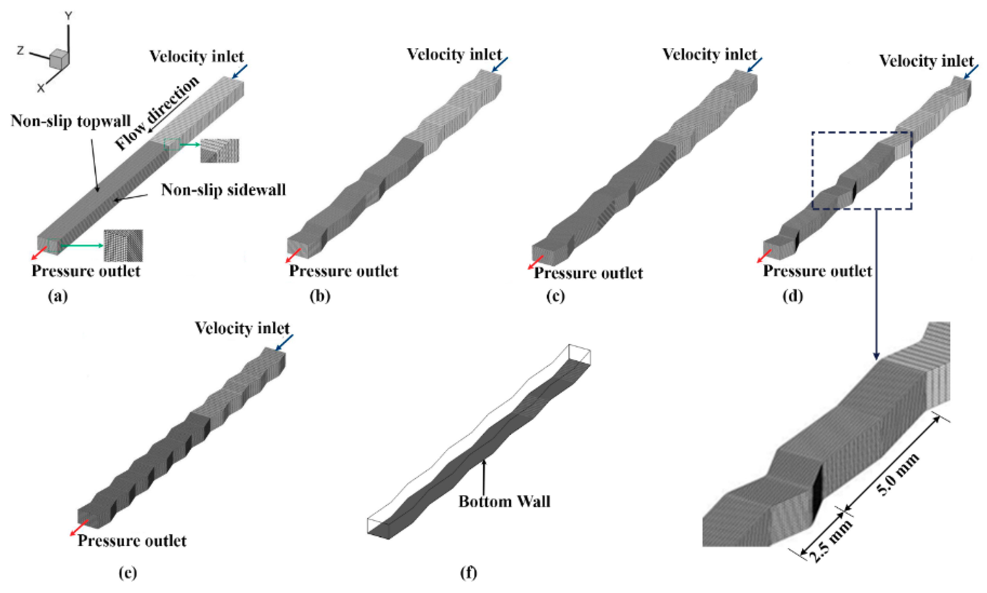
2.3. Computational Domain and Boundary Conditions

The schematic of the three-dimensional computational domain with 191,748 hexahedral elements is shown in Figure 1. Figure 1a represents the straight channel (reference case), while Figure 1b–d represents the hybrid sinusoidal (Design 1), hybrid sinusoidal (Design 2) and hybrid sinusoidal (Design 3), respectively. Also, Figure 1e,f depicts sinusoidal (Design 4) and sinusoidal (Design 5). In all cases, the 25 mm channel has a cross-section of 400 μm × 600 μm.
The 25 mm long channels have been sectioned into two parts, the flow building part and the flow core part. The partitioning is done to ensure the flow across the channel is fully developed. Table 1 shows the geometric dimensions of the CFD model.
On all the channel walls at t = 0, a no-slip condition is applied. At the channel inlet and exit ports, the velocity and pressure at t = 0 are fixed at zero, respectively. Also, for all cases, the patched droplet is positioned 12 mm from the inlet port along the axis line. This is to ensure that the airflow is fully developed before meeting the droplet. For all cases tested, the bottom wall, which is the GDL surface, is hydrophobic at a fixed contact angle of 120° [30,31], and the contact angle at the side and top wall were varied from 120° to 45°. Details of the operating conditions are shown in Table 2. For the multiple droplet simulations, the three droplets were positioned at the centerline and arranged 12 mm, 13 mm, and 14 mm from the channel inlet. As for the boundary conditions, velocity-inlet is set at the inlet while the outlet is set as pressure-outlet.

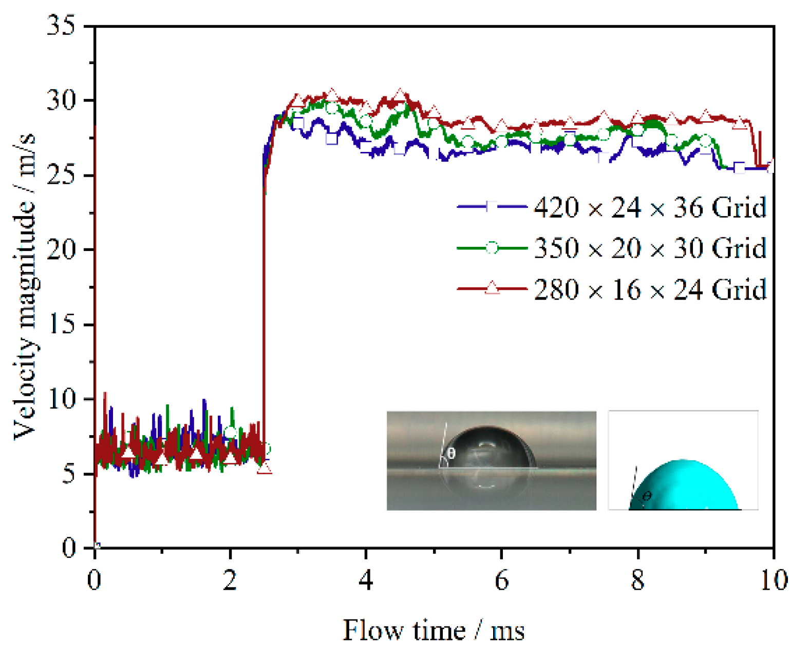
2.4. Grid Independence Test Analysis

To ensure accuracy of the results, an independence test analysis of the hexahedron grid cells has been conducted, with velocity magnitude and droplet shape as tools for validation, and the results showed a negligible difference (Table 3).
For the test, we adopted a similar approach used in our previous work [27], where the grid number on every direction is increased [32] in a stepwise manner by 20% and velocity magnitude is used as a validation criterion. As shown in Figure 2, the tested grid numbers showed a minor difference, and as such, the 350 × 20 × 30 grid was employed to reduce computational time while satisfying the requirement for spatial convergence. The computation fluid domain meshes into 191,748 hexahedral cells with a maximum volume of 8.92226 × 10⁻¹⁴ m3 and a minimum volume of 2.18136 × 10⁻¹⁴ m3 for each hex cell. The grid size measures approximately 2.05754 × 10⁻⁴ m and 2.10592 × 10⁻⁵ m in the X- and Y-directions, respectively while the grid size along the Z-direction measures 3.7 × 10⁻⁵ m in the flow channel domain.
Comparatively, our droplet shape on the surface with a contact angle of 80° was the same as the experimental observation of Nishida et al. [33]. The size of the time step considered suitable for this analysis is 1 × 10⁻⁶ s and was implemented due to the insignificant effect that 1 × 10⁻⁵ s had on the simulation results. Consequently, droplet expulsion time as compared to the works of Hou et al. [34] indicated a very insignificant difference.
Furthermore, in this grid test study, the assumed GDL surface (bottom wall) and all the walls of the channel are in the no-slip boundary condition. During this test, the GDL surface contact angle is set at 120°, and the contact angles of the entire channel walls are similar and set at 120°. At the channel inlet and outlet, respectively, a velocity inlet boundary condition of 12.5 m s−1 and a pressure outlet boundary condition of 1 atm is applied. Also, the force of gravity is considered along the negative direction of Y.

3. Results and Discussion

Several cases were simulated using five different sinusoidal channel designs, including a reference case. These sinusoidal channel designs are grouped into hybrid and non-hybrid channel configurations: Design 1 and Design 2 (hybrid pitch with uniform amplitude of 0.1 mm and 0.2 mm, respectively), Design 3 (hybrid pitch with hybrid amplitude of 0.1 mm and 0.2 mm), Design 4 and Design 5 (non-hybrid channels with pitches of 2.5 and 5 mm, respectively). The non-hybrid channels had a uniform amplitude of 0.1 mm, as shown in Table 1. The air inlet velocities of 12.5 ms−1 and 10 ms−1 used here are based on the typical operating conditions used in [27].

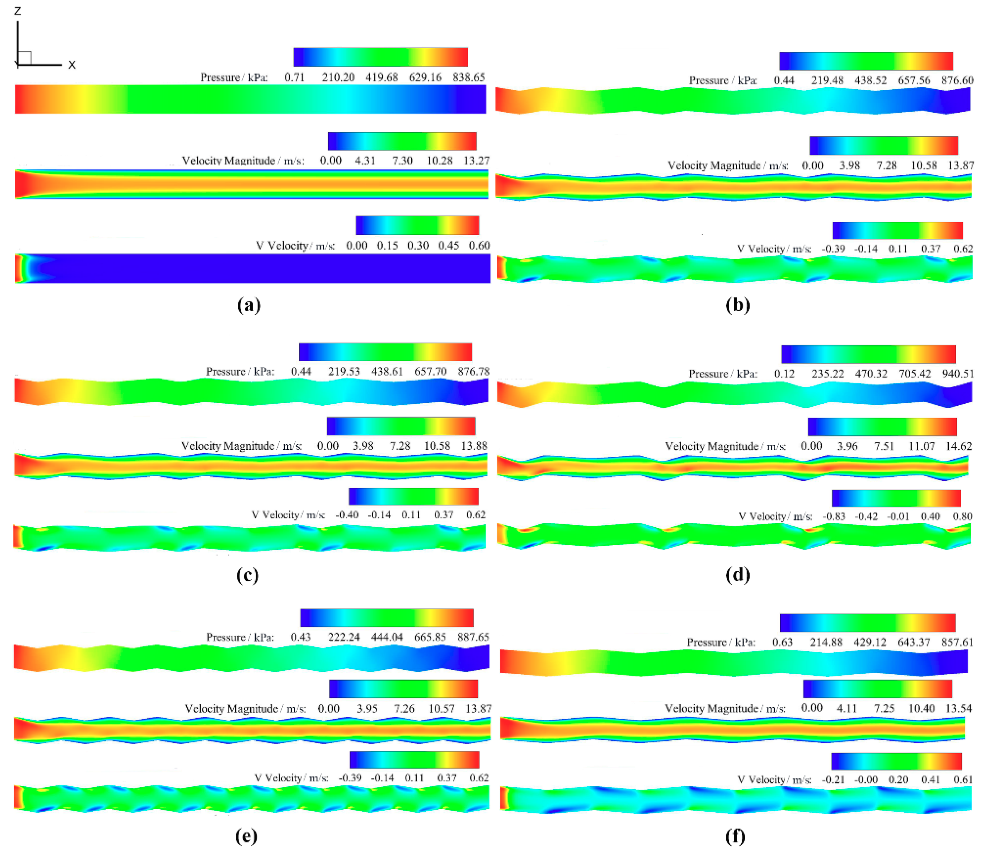
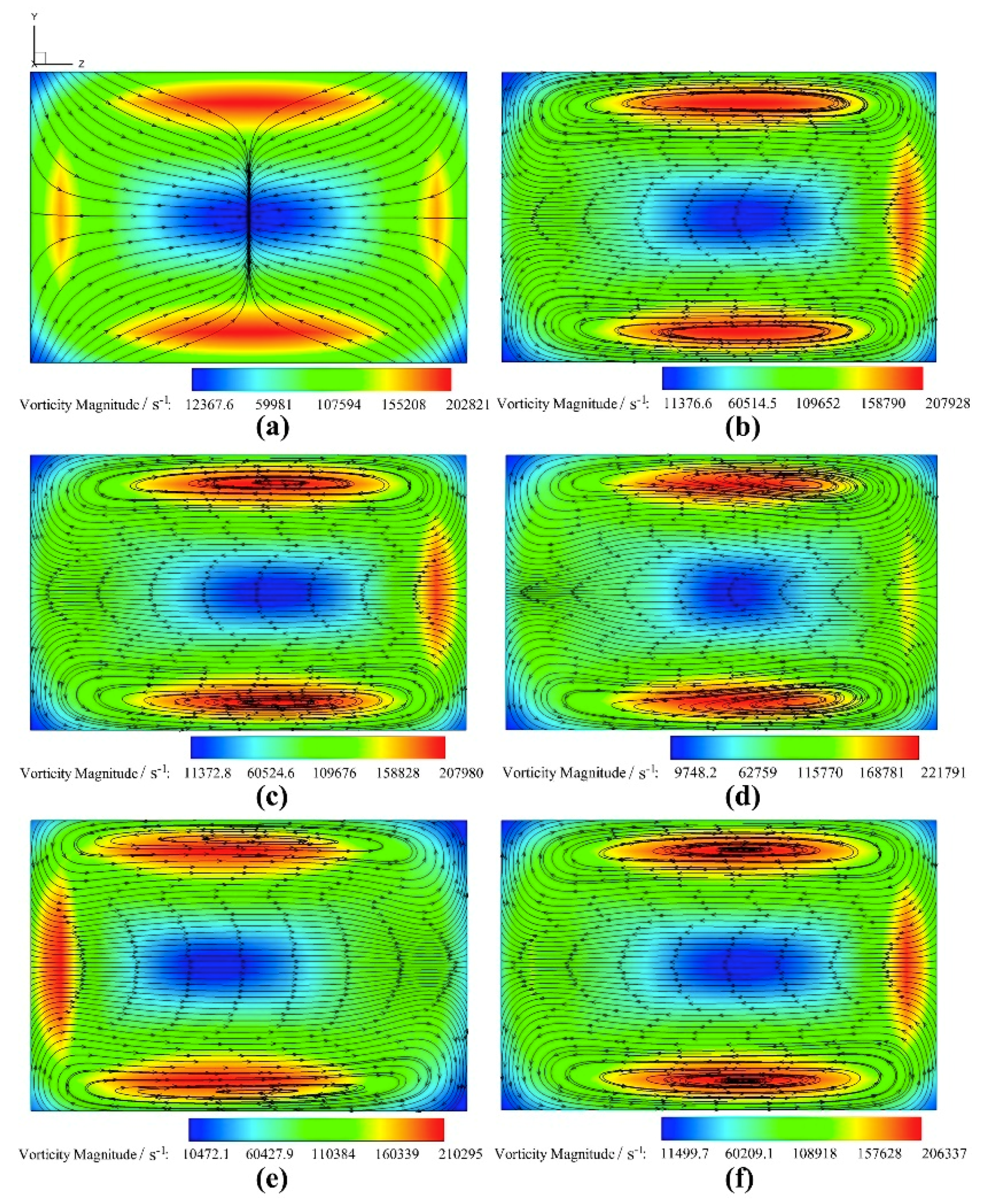
3.1. Single-Phase Flow Characteristics of the Channels Under Investigation

The single-phase flow behaviour of the straight and the sinusoidal channel designs are shown in Figure 3. The pressure-drops, velocity, and vertical component velocity (V-velocity) magnitudes in the Z–X plane are shown in Figure 3a–f. As shown in Figure 3a, the straight case yielded the least pressure drop, velocity magnitude, and V-velocity across the channel.
The maximum V-velocity attained is just 0.00022 mm away from the inlet point and consequently, weak at the channel downstream. This is as a result of the straight shape, which makes the flow laminar at all locations. The straight nature of the channel is responsible for the low-pressure drop because the only friction that occurs in this channel shape exists only between the fluid and the straight channel walls, unlike in the wavy flow channel cases where there is flow resistance as a result of the periodic side walls. These undulating side walls lead to an increase in the pressure drop across the channel as a result of the heightened fluid velocity and wall friction, in contrast to the straight channel which is purely straight with little or no obstruction to flow. The pressure drop and the fluid velocity magnitude are therefore smaller in the straight channel case compared to the wavy cases. Thus, this explains the reason for the inherent poor reactant mixing [35] and low cell performance compared to the sinusoidal-shaped channel design [8].
It is also evident that the increase in the channel amplitude raises the pressure drop and velocity magnitude, as revealed in Design 1 and Design 2 (Figure 3b,c). This explains the improvement recorded in the quick liquid discharge, which has been discussed further in subsequent sections. Both designs are similar in pitch and amplitude arrangement, except for the difference in channel amplitude. Design 1 has a smaller amplitude of 0.1 mm while Design 2 has an amplitude of 0.2 mm, and as such, this is responsible for the variance in pressure drop and velocity magnitude. This result agrees with the findings of Xu et al. [22] on the significant influence that geometric configurations have on flows in wave-like channels. They opined that the geometric parameters of wave-like channels have a considerable impact on the pressure drop, water removal behaviour and detachment time. They found that geometric parameters such as channel pitch greatly influence the pressure oscillation. This is also in line with the findings and, indeed, one of the benefits of hybrid models. Thus, as much as high-pressure drops accompany an increase in the number of bends, increasing the channel amplitude also plays a role. This rise in pressure drop is linked to friction and momentum alternation as a result of the change in the flow direction. While the small pitch helps raise the average fluid velocity, the larger pitch acts to relieve the pressure oscillation.
Design 3 is also a hybrid sinusoidal design comprised of two pitches and two amplitudes. As seen in Figure 3d, the geometric configuration hugely affects the flow pattern. A hybrid sinusoidal channel with dual-amplitude yields a very high-pressure drop and velocity magnitude and as such, may not be suitable for application in PEMFCs. This design affects fluid flow with irregular change in flow direction as a result of the non-uniform dual-amplitude arrangement. This behaviour generates eddies which interfere with the flow pattern and thus give rise to extra pressure losses. However, the design would be most useful for systems where thorough reactant mixing is required because of the very high V-velocity magnitude. This V-velocity represents the convective flow capable of enhancing mass transfer [36].
Designs 4 and 5 are non-hybrid sinusoidal channel designs tested to check the improved performance in the hybrid cases (Design 1 and Design 2). The configuration of Design 4 has many repeating ordered pitch and amplitude arrangements, which is responsible for the high-pressure drop inherent in the design (Figure 3e). While the pressure drop in the Design 5 configuration is small compared to Design 4 and all the hybrid designs (Designs 1, 2, and 3), this is as a result of the fewer numbers of regular repeating pitch arrangements and the pitch size, both of which are responsible for the reduced pressure drop. As such, the fewer the number of pitches, the lower the pressure drop.
On the contrary, an increase in the number of regular repeating pitches tends to raise the fluid’s velocity magnitude slightly, as shown in Figure 3e,f. This trend is also noticed in the V-velocity magnitude values of both designs. The vertical component velocity, as shown in Figure 3b–f, is enhanced because of the wavy nature of the sinusoidal channel design. Here, the convection is stronger and distributed along the channel path with peaks at the side wall troughs. This improvement is as a result of the secondary force peculiar in sinusoidal flow channels. As such, while the smaller pitch tends to raise the pressure drop, the more extended pitch diminishes it. Therefore, the choice of a hybrid sinusoidal channel is positive as it taps into the advantages offered by both small and long pitches.
Compared with the straight channel, the pressure drop in the sinusoidal channel designs is slightly higher. However, while this may pose as a disadvantage as a result of the inherent pumping loss, this penalty is negligible compared to the many benefits. The slight high-pressure gradient is useful in ensuring efficient water removal, especially at the cathode side of the PEMFC [8]. As such, the possibility of flooding in hybrid sinusoidal channels is nearly impossible with improved gas flow speed and heat management. The authors believe this slight pressure drop increase is a price worth paying for improved mass transport and overall cell performance. Consequently, the curvy nature and pitch arrangement are responsible for the slight pressure drop increase and heightened velocity magnitude in the cathode gas channel compared to the straight channel.

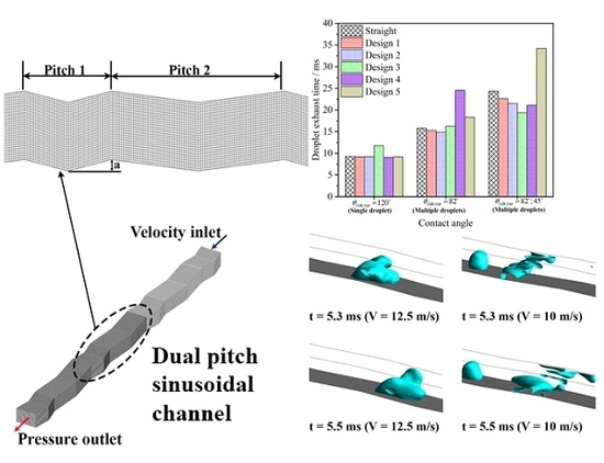
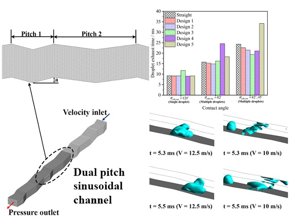
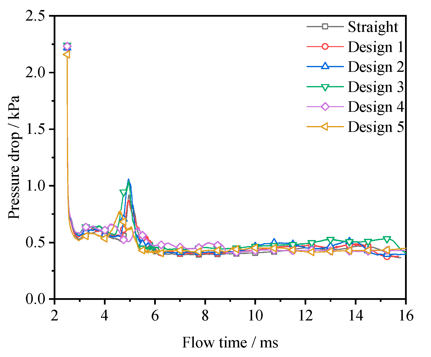
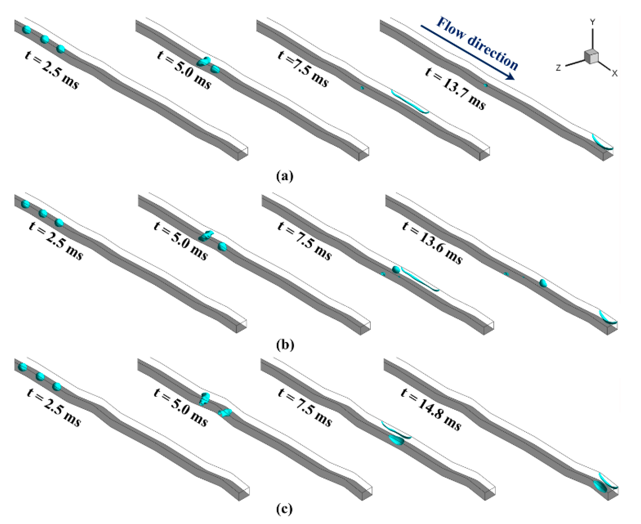
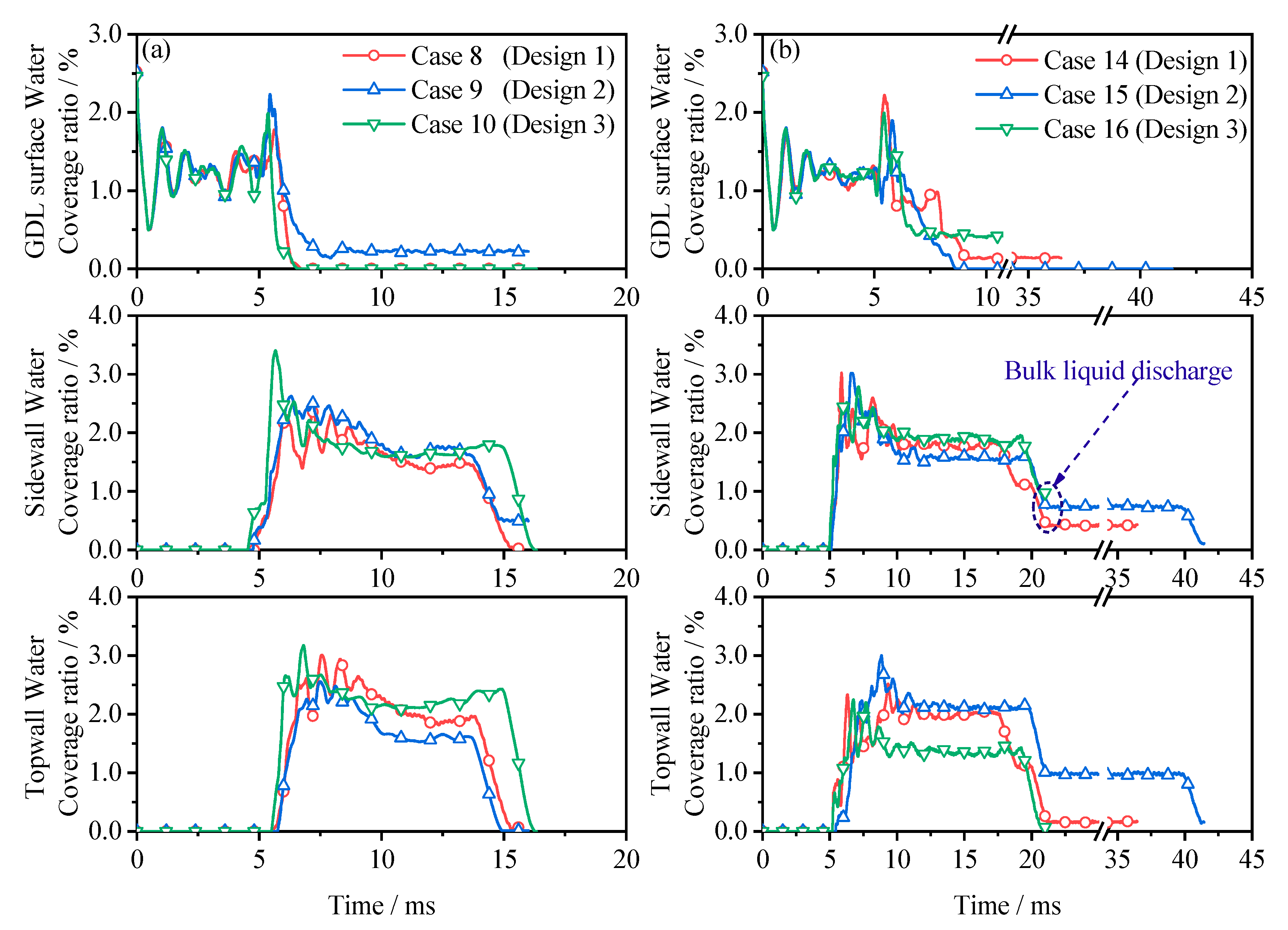
3.2. Significance of Channel Architecture

In the present study, we used the straight rectangular channel as a reference to analyse the effectiveness of the proposed hybrid sinusoidal channel designs. The curved side walls of the sinusoidal channel design induce some form of secondary flow effect across the channel, which leads to a two-phase flow characterised by a degree of direction. This secondary flow effect causes the sluggish fluid near the non-slip walls to be easily replaced with rapid moving fluid, thus intensifying the viscous friction around the walls. Figure 4 further highlights the significance of the channel configuration with the aid of the vortex magnitude contours and streamlines.
The results agree with the previous findings of [7], which further show that an increase in vortex magnitude accompanies a rise in the amplitude. However, an excess of this rotational flow can delay droplet discharge, and as such, a moderate vortex is only required in PEMFC microchannels for efficient water expulsion. Given this, the hybrid sinusoidal designs, especially Design 1 and 2, provide such, and this explains the reason for the significantly enhanced water expulsion performance as shown in Figure 5. In a similar vein, for Design 3 (i.e., dual amplitude) as seen in Figure 4d, the channel architecture is responsible for the increased fluid kinetic energy with a corresponding rise in vortices magnitude. Dual-pitch and amplitude arrangement significantly raise the velocity magnitude, which in turn affects the pressure drop correspondingly. Therefore, juxtaposing the pitch and amplitude is one way of enhancing fluid flow and altering the pressure drop penalty.
Accordingly, Figure 5 shows the water expulsion of PEMFC channels of different configurations comprising the straight, hybrid, and non-hybrid sinusoidal channel designs. The structural shape of gas flow channels allows for better reactant and water transport, which leads to improved overall cell performance.
As shown in Figure 5, the water removal rates in the hybrid sinusoidal channels were slightly better than the non-hybrid sinusoidal and straight channels. This is as a result of the dual-pitched arrangement with the shorter pitch responsible for improved fluid velocity magnitude while the long pitch relieves the excess pressure oscillation. However, Designs 1 and 2 proved to be much superior in terms of quick water expulsion, and this goes on to show the significant influence of channel architecture on flow behaviour [22].
Additionally, Figure 6 illustrates the variation of the two-phase pressure drop fluctuation during the flow times 2.5–16 ms for different channel designs. At t = 5 ms, the first two droplets coalesced, and this increase in droplet mean size narrowed the flow passage, thus leading to an increase in pressure across the channel. Subsequently, the pressure across the flow path regained stability after a short period—this is as a result of severe droplet deformation and ascension to the side and top walls.
The proposed hybrid sinusoidal channels after droplet stabilisation had a slightly comparable pressure drop with the conventional channel designs. More so, the proposed designs yielded a 3.58%, 4.98% and 10.9% increase in average pressure drop in Designs 1, 2 and 3, respectively, compared to the conventional straight channel. This positive characteristic means improved mass transport and water discharge, which implies that under different operating conditions, the channel architecture affects droplet removal. In the range of varying wall contact angles, the water removal rate performance of the hybrid sinusoidal channels (Designs 1 and 2) is better than the other geometric shapes investigated. Therefore, the proposed hybrid channel designs, especially Designs 1 and 2, appear to be consistent and show better water removal capacity.
Finally, the hybrid channel designs performed better than the ordered sinusoidal channels with improved flow characteristics, all of which is beneficial to PEMFC overall performance in regard to reactant transportation, heat management, and water removal.

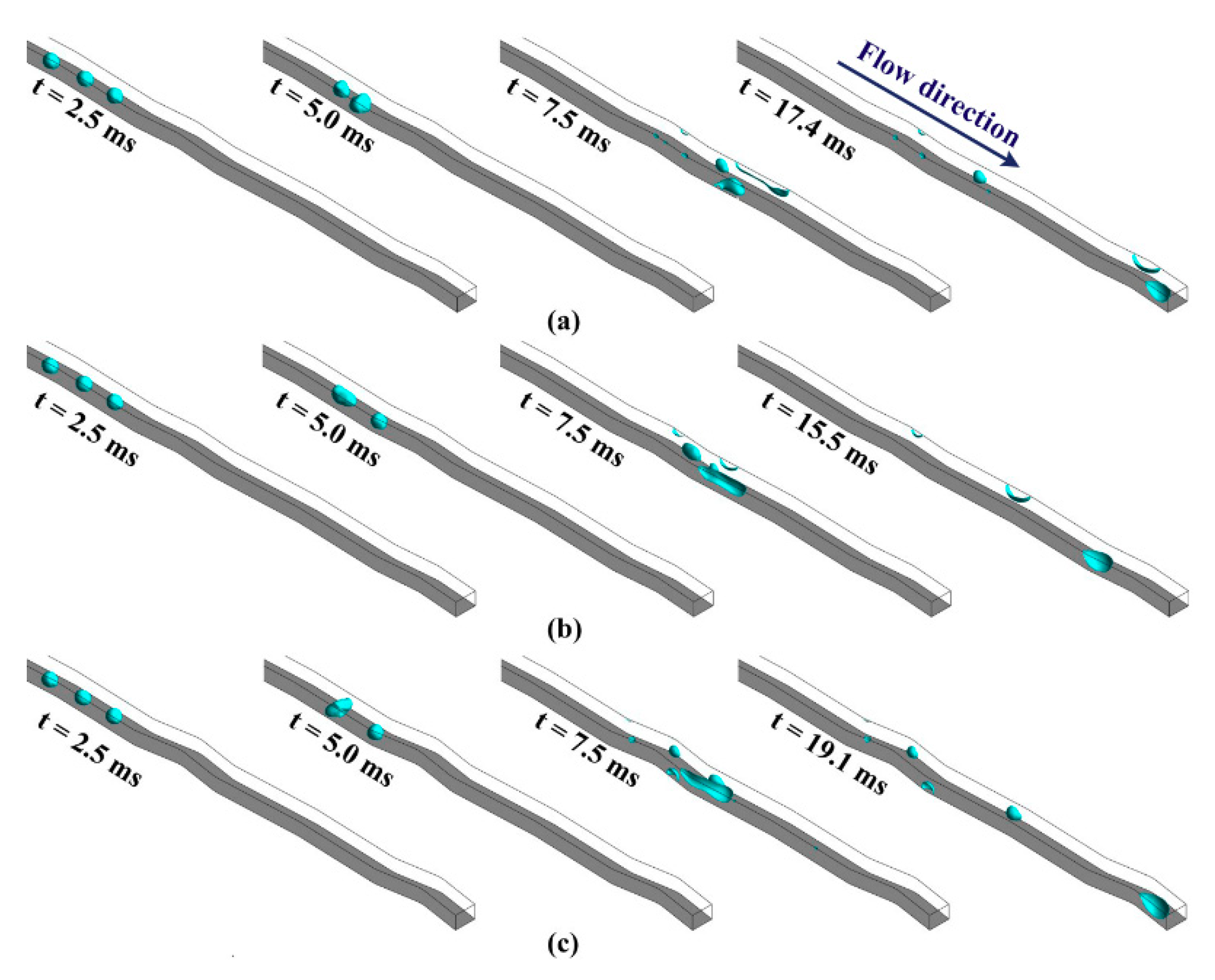
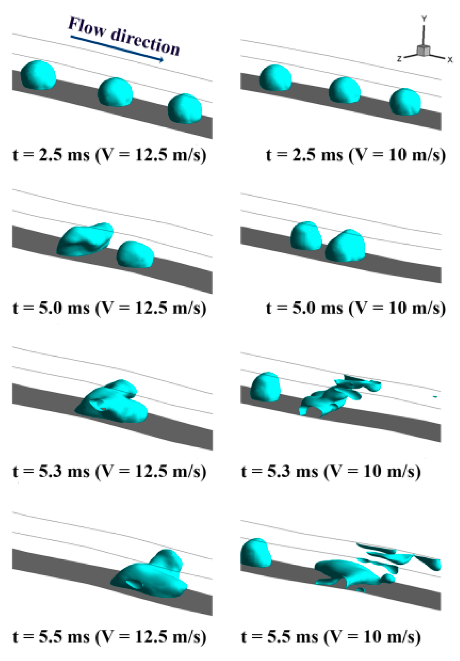
3.3. Gas Inlet Velocity Effect

The air inlet velocity greatly influences droplet detachment, deformation, and discharge in microchannels. One can note for all configurations that the liquid water expulsion rate decreases as the inlet gas velocity reduces (Figure 7 and Figure 8), which is a phenomenon caused by the reduced inertia.
The inertia force, imparted on the droplet as a result of airflow intensity, affects removal rate, droplet deformation, and shape. Regarding the comparison between the different configurations under varying inlet velocities, the hybrid sinusoidal channels have a peculiar pitch–amplitude arrangement which improves water exhaust and droplet break up. Therefore, at a higher gas inlet velocity, inertia forces are stronger [37], and this distorting force deforms the droplet and facilitates its removal in the hybrid channels, whereas at a lower inlet velocity, the viscous forces are more dominant [38]. This implies that the friction effect appears to be larger than the inertial forces, thereby slowing down droplet motion.
In Figure 7, under high gas feed conditions, the inertia force induced on the droplets deforms the merged droplets at t = 5.0 ms. Under higher inlet velocity conditions, there is a higher tendency for the liquid water slug to ascend entirely through the side walls to the top wall, and this is as a result of the high fluid velocity. At low inlet velocity conditions (Figure 8), the merged droplets appear less deformed at t = 5.0 ms, except for Design 3 channels. As seen in Figure 7c and Figure 8c, the merged droplet is visibly deformed, a phenomenon caused by higher gas velocity in the channel due to the channel shape. As a result of the dual hybrid nature of Design 3 channels, the intensity of the secondary flow within the channel is amplified and is thus capable of deforming and breaking droplets up even at low speed, as seen in Figure 8c.
Also, at a higher inlet gas velocity (Figure 7), there are fewer daughter droplet particles compared to Figure 8 (lower inlet velocity) where the daughter particles increased. The proposed hybrid sinusoidal channel also tends to retain more water than the other channels, including the straight channel design. These trapped droplets are found mostly on the side and top wall of the channel area, as shown in Figure 9. From this result, it can be inferred that high inlet gas velocity favors the hybrid sinusoidal channels and is beneficial to quicker water discharge.

3.4. Droplet Interaction

Three same-sized droplets placed on the axis line (Figure 10) at different inlet velocities (V = 12.5 ms−1 and 10 ms−1) are used to study droplet interaction processes during coalescence. So, at a high inlet velocity (V = 12.5 ms−1), the upper part of the first merged droplets appears more deformed compared to the lesser deformation noticed at low speed. Under the high-speed condition, the droplet mean size appears larger with an imbalance between the forces acting on the merged droplet. This phenomenon is as a result of the increase in inertia and shear forces. This imbalance is responsible for the deformation and faster droplet exhaust time.
Conversely, at low speed, the mean size of the merged droplet is not too large as compared to the former. It can also be seen in Figure 10 that the merged droplet broke up quite a bit earlier, which means that at a low Reynolds’ number (Re), the surface properties of the channel become more significant and delays droplet removal [39]. As such, it can be said that the inlet gas velocity influences droplet height, movement, shape, and exhaust time in PEMFC channels. Therefore, droplet coalescence at high inlet gas velocity is beneficial to droplet average speed and removal rate.

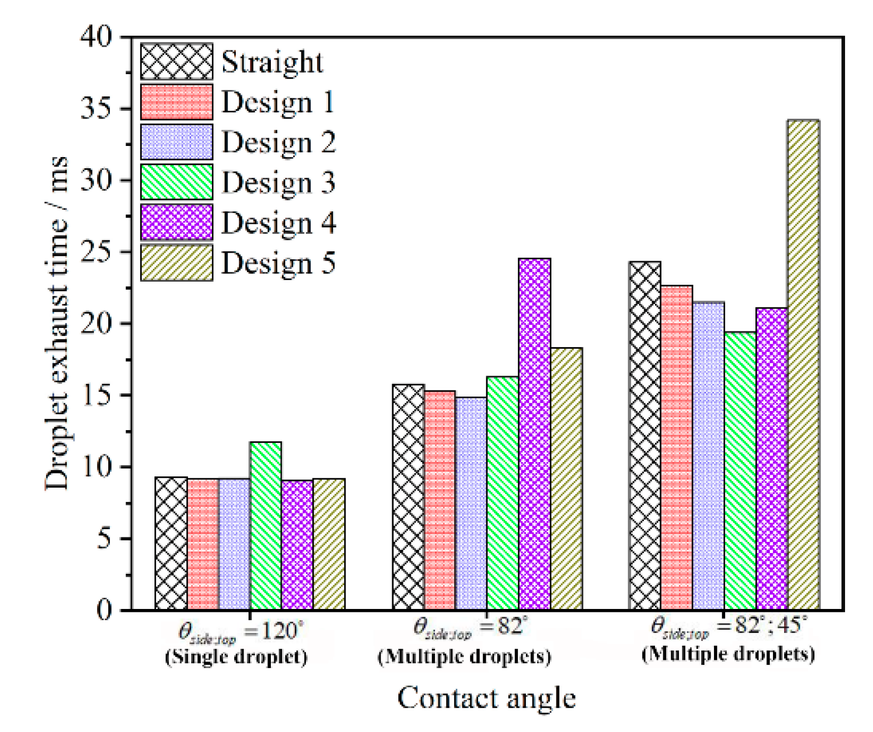
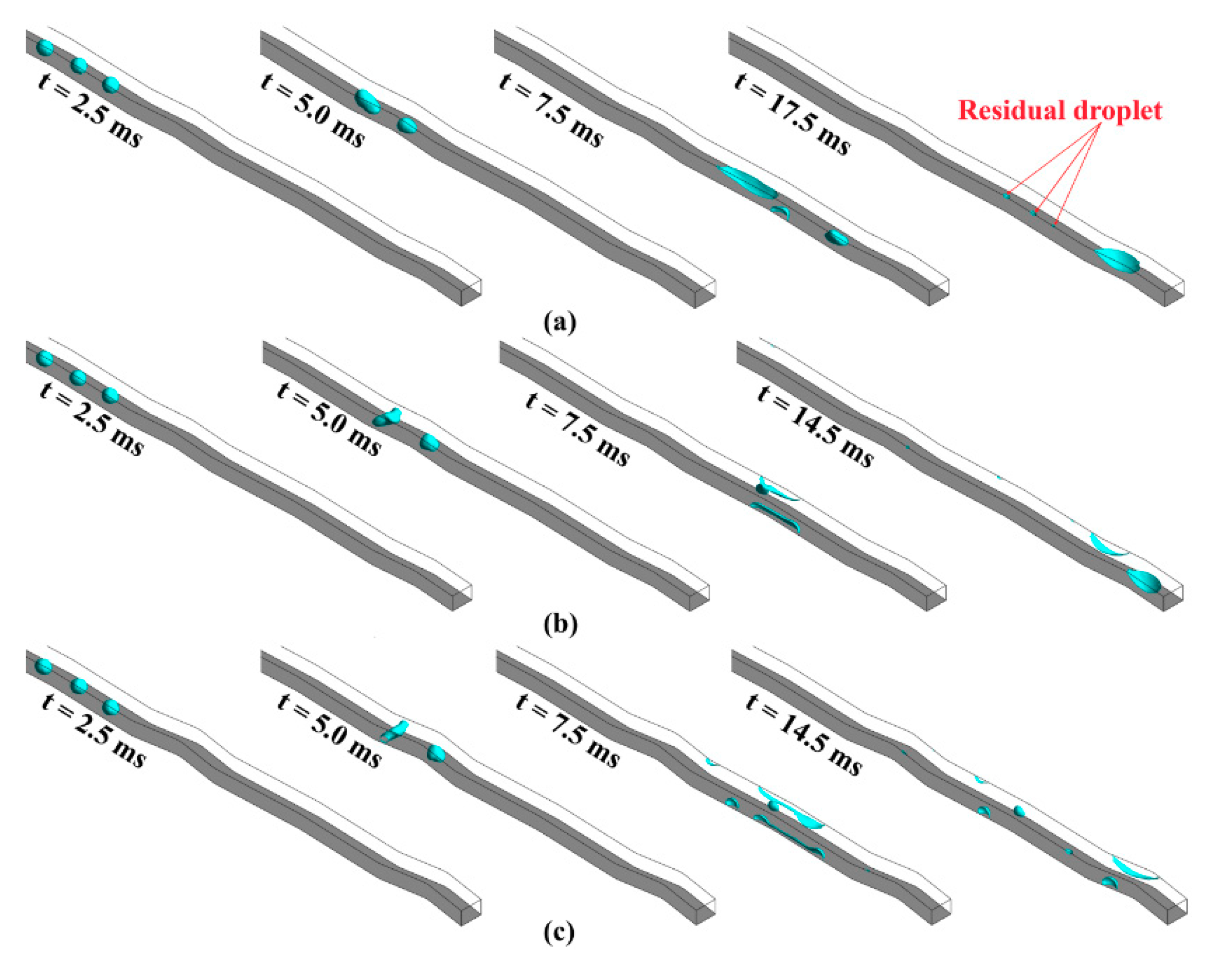
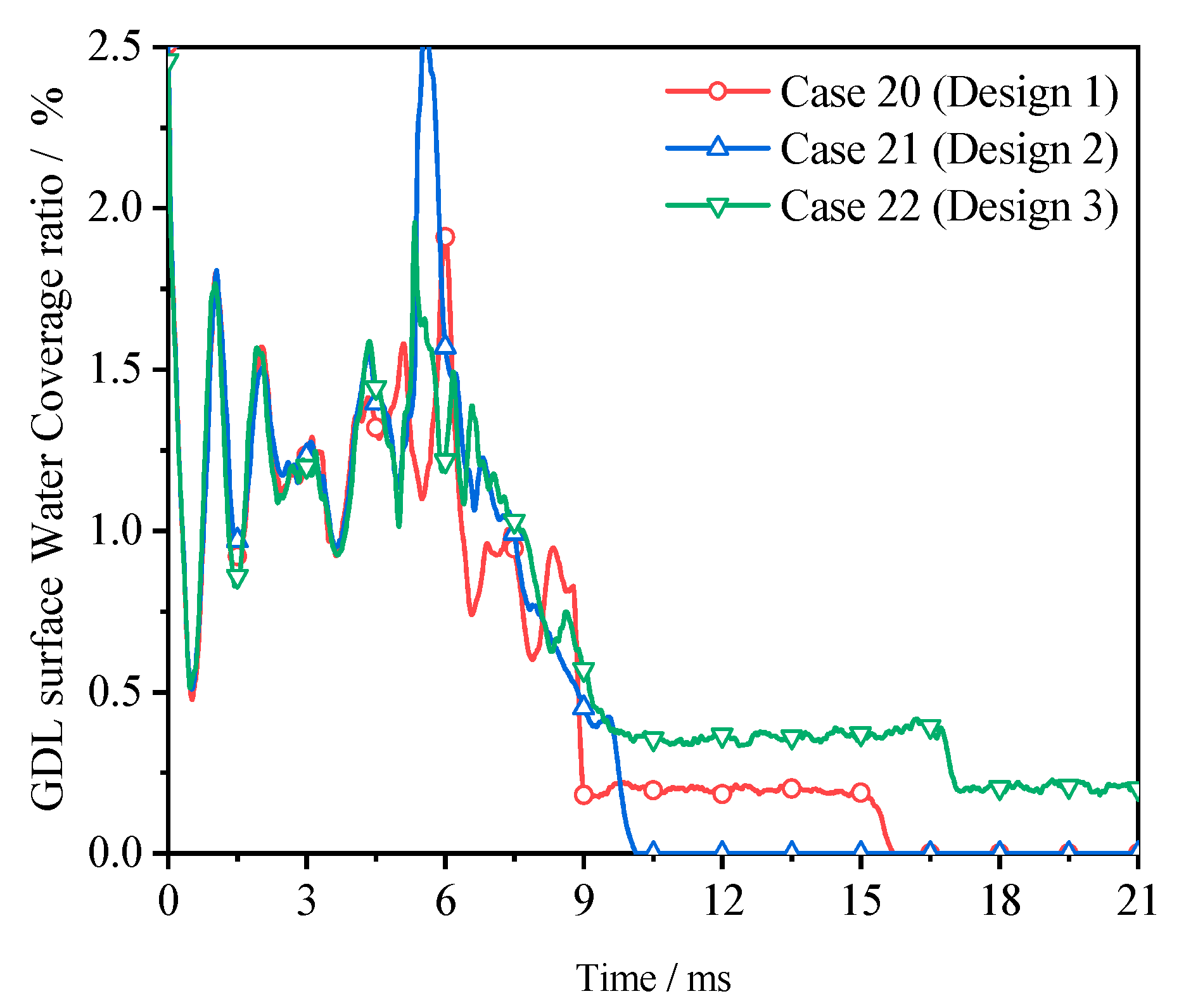
3.5. Surface Wettability Effect

The present work also studied the coalescence of three droplets under varying wall contact angles. Figure 7 and Figure 11 reveal the effect that wall wettability has on water transportation in PEMFC hybrid and non-hybrid sinusoidal channels. The inlet gas velocity for all cases is kept at 12.5 m/s and checked against different wall conditions of θside; top = 82°; 82° and θside; top = 82°; 45°, respectively. It appears that droplet removal is quicker if the side and top walls are slightly hydrophilic (θside; top = 82°; 82°).
This peculiar characteristic is because of the reduced capillary forces when the side and top walls are made slightly hydrophilic. However, making the top wall more hydrophilic increases the chances of the droplet ascending to the top wall while delaying its exhaust time. Reducing the contact angle at the top wall results in an enlarged water surface coverage area of the top wall, and a vast number of tiny droplets at the channel area. In Figure 8 (θside; top = 82°; 82°), one can see that the droplet exhaust rate is faster in the hybrid type channels than the non-hybrid cases. Also, the non-hybrid case (Design 5) has the least GDL surface coverage ratio compared to the hybrid cases (Design 1 and Design 2), completely detaching from the GDL surface earliest, while as shown in Figure 11 (θside; top = 82°; 45°), the water exhaust time is longer with more of the liquid coverage on the top wall. However, under this wall condition, the configuration of Design 3 has the fastest removal rate, but with more trapped broken droplets at the wall interfaces (Figure 11c and Figure 12). This is because of the high gas velocity build up in the channel capable of deforming and breaking up the droplet.
From the result, the liquid water expulsion rate under both wall conditions favours the hybrid wavy channels. However, for optimum water removal, especially under hydrophilic wall conditions, a slightly hydrophilic wall is best recommended, as this would facilitate total water detachment off the GDL surface, quicker water removal, and improved reactant transportation to reactant sites. However, it is also important to note that making the side and top wall hydrophobic significantly improves water ejection (see Figure 5).

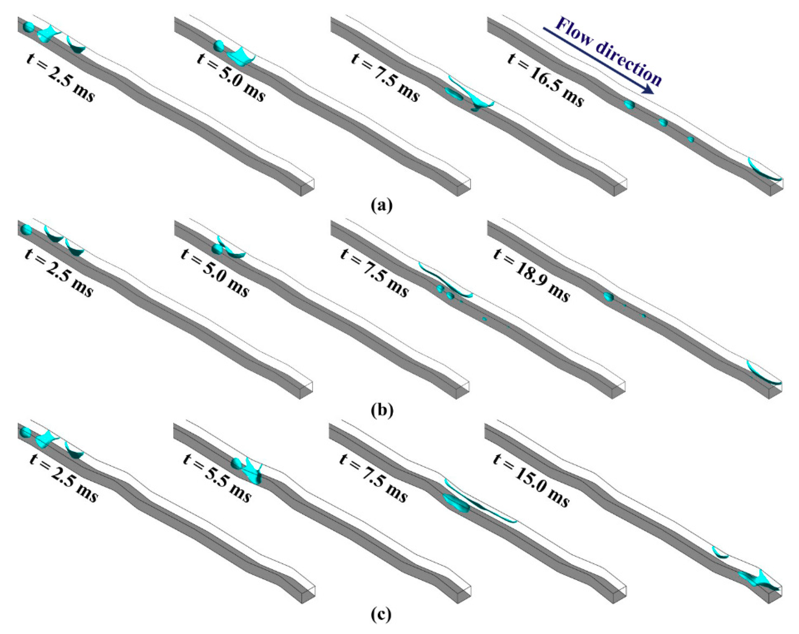
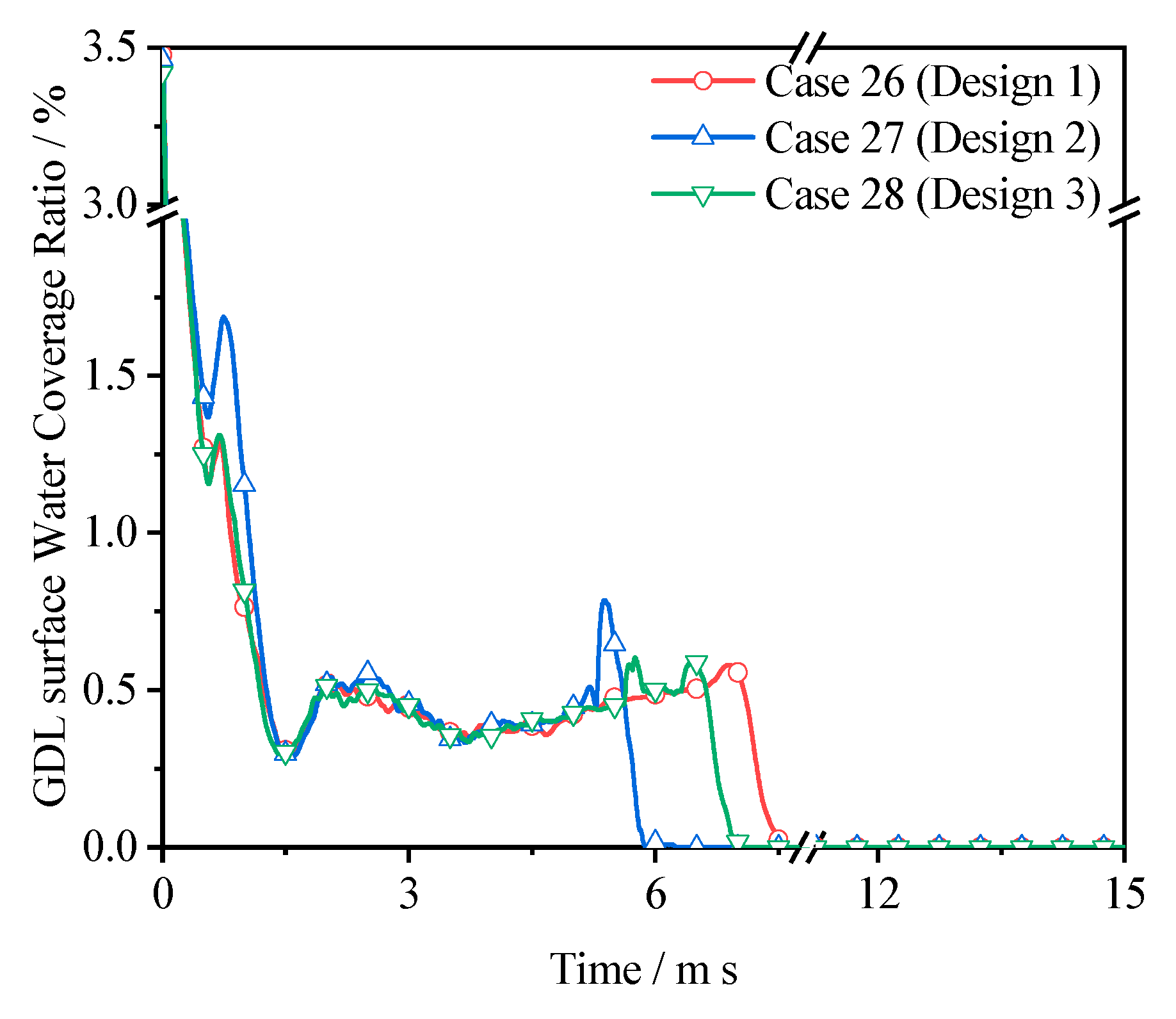
3.6. Droplet Size Effect

Additionally, we evaluated the effect of droplet size to mimic operational conditions where the droplets formed have different sizes. As such, for this investigation, we placed three droplets (r1, r2 and r3) in line at the channel base with radiuses of 200 µm, 250 µm and 250 μm, respectively. Figure 8 depicts the temporal droplet evolution with all three droplets having the same radius (200 μm), while Figure 13 shows the temporal droplet evolution of three droplets with radiuses of 200 µm, 250 µm, and 250 μm, respectively. Figure 8 and Figure 13 prove that an increase in droplet size leads to a shorter exhaust time. This means that as the droplet size increases, the acceleration rate of the coalesced droplet increases too. The increased droplet acceleration rate is because of the substantial interface area formed by the merged droplet, which leads to increased surface turbulence. The increased surface area of the droplet results in a heightened imbalance between the forces acting on the droplet. Therefore, more surface energy is converted to kinetic energy, which is responsible for the increased droplet deformation and acceleration rate.
Figure 8 and Figure 13 further reveal a 48.8%, 17.4% and 12.7% improvement in water exhaust capacity in Designs 2, 3 and 1, respectively, which implies that even under conditions of excessive water accumulation, the hybrid sinusoidal channels can efficiently evacuate water in the channels. Also, a quick and complete water detachment off the GDL surface is noticed in all channel designs with quicker complete detachment in Design 2 (Figure 14). The improved removal rate, even at the increased amount of water in the channels, could best be explained as a direct result of the fluid’s kinetic energy being more dominant. The geometric configuration of the channel also plays a significant role, especially in regard to the quickness of droplet ascension to the top wall.

4. Conclusions

This study presented the two-phase flow modelling and simulation of novel hybrid sinusoidal PEMFC channels using CFD with the three-dimensional VOF model. The water removal rate of the novel hybrid designs is compared to the non-hybrid sinusoidal and straight channels. The effect of geometric channel configuration, inlet gas velocity, wall wettability, and droplet size are reported. Our findings and conclusions are:
  • The proposed hybrid sinusoidal flow channels have slightly improved water exhaust capacities, a higher gas velocity magnitude, and vertical component velocities. Design 2 hybrid configuration is recommended because of its excellent adaptability to different wall conditions and improved water exhaust capacity.
  • The size of channel amplitude is one geometric parameter which significantly affects pressure drop, gas velocity magnitude, and average droplet speed. The velocity magnitude of the proposed hybrid sinusoidal designs (Designs 1, 2, and 3) is approximately 4.52%, 4.60%, and 10.17% higher than the straight channel, respectively. This implies that designers can choose different sizes based on expected cell performance.
  • High inlet gas velocity is highly beneficial to droplet deformation, shear, and quicker discharge.
  • Droplet coalescence and size quickens droplet deformation and discharge rate.
  • Slightly hydrophilic channel walls facilitate quick and complete droplet detachment from the GDL surface; this would aid reactant transport to active reaction sites.
  • The liquid water removal is significantly affected by the time the droplet touches the side wall: the earlier the contact time, the more prolonged the droplet residence inside the channel.
The proposed hybrid sinusoidal design is unique since it combines the advantages of both pitch designs. Therefore, it is able to balance these two indexes, making it a suitable candidate for PEMFC applications.

Author Contributions

Conceptualization, I.S.A.; Data curation, I.S.A.; Investigation, I.S.A.; Resources, W.C. and F.P.; Supervision, Q.D., J.X. and K.J.; Writing—original draft, I.S.A.; Writing—review and editing, Y.H. and K.J.

Funding

This work is supported by the National Key Research and Development Program of China (2018YFB0105505), the China–UK International Cooperation and Exchange Project (Newton Advanced Fellowship) jointly supported by the National Natural Science Foundation of China (Grant No. 51861130359) and the UK Royal Society (Grant No. NAF/R1/180146), and the National Natural Science Foundation of Tianjin (China) for Distinguished Young Scholars (Grant No.18JCJQJC46700).

Conflicts of Interest

The authors declare no conflict of interest.

References

  1. Song, Y.; Asadi, M.; Xie, G.; Rocha, L.A.O. Constructal wavy-fin channels of a compact heat exchanger with heat transfer rate maximization and pressure losses minimization. Appl. Therm. Eng. 2015, 75, 24–32. [Google Scholar] [CrossRef]
  2. Sui, Y.; Teo, C.J. Fluid flow and heat transfer in wavy microchannels. Int. J. Heat Mass Transf. 2010, 53, 2760–2772. [Google Scholar] [CrossRef]
  3. Xin, R.C.; Tao, W.Q. Numerical prediction of laminar flow and heat transfer in wavy channels of uniform cross-sectional area. Numer. Heat Trasnf. Part A Appl. 1988, 14, 465–481. [Google Scholar] [CrossRef]
  4. Chen, C.K.; Cho, C.C. A combined active/passive scheme for enhancing the mixing efficiency of microfluidic devices. Chem. Eng. Sci. 2008, 63, 3081–3087. [Google Scholar] [CrossRef]
  5. Hatami, M.; Safari, H. Effect of inside heated cylinder on the natural convection heat transfer of nanofluids in a wavy-wall enclosure. Int. J. Heat Mass Transf. 2016, 103, 1053–1057. [Google Scholar] [CrossRef]
  6. Leng, C.; Wang, X.D.; Yan, W.M.; Wang, T.H. Heat transfer enhancement of microchannel heat sink using transcritical carbon dioxide as the coolant. Energy Convers. Manag. 2016, 110, 154–164. [Google Scholar] [CrossRef]
  7. Lin, L.; Zhao, J.; Lu, G.; Wang, X.D.; Yan, W.M. Heat transfer enhancement in microchannel heat sink by wavy channel with changing wavelength/amplitude. Int. J. Therm. Sci. 2017, 118, 423–434. [Google Scholar] [CrossRef]
  8. Atyabi, S.A.; Afshari, E.A. numerical multiphase CFD simulation for PEMFC with parallel sinusoidal flow fields. J. Therm. Anal. Calorim. 2018, 135, 1823–1833. [Google Scholar] [CrossRef]
  9. Zhang, G.; Xie, B.; Bao, Z.; Niu, Z.; Jiao, K. Multi-phase simulation of proton exchange membrane fuel cell with 3D fine mesh flow field. Int. J. Energy Res. 2018, 42, 4697–4709. [Google Scholar] [CrossRef]
  10. Liu, H.; Li, P.; Hartz, A.; Wang, K. Effects of geometry/dimensions of gas flow channels and operating conditions on high-temperature PEM fuel cells. Int. J. Energy Environ. Eng. 2015, 6, 75–89. [Google Scholar] [CrossRef]
  11. Zhang, G.; Jiao, K. Three-dimensional multi-phase simulation of PEMFC at high current density utilizing Eulerian-Eulerian model and two-fluid model. Energy Convers. Manag. 2018, 176, 409–421. [Google Scholar] [CrossRef]
  12. Ferreira, R.B.; Falcão, D.S.; Oliveira, V.B.; Pinto, A.M.F.R. Numerical simulations of two-phase flow in proton exchange membrane fuel cells using the volume of fluid method—A review. J. Power Sources 2015, 277, 329–342. [Google Scholar] [CrossRef]
  13. Akhtar, N.; Qureshi, A.; Scholta, J.; Hartnig, C.; Messerschmidt, M.; Lehnert, W. Investigation of Water Droplet Kinetics and Optimization of Channel Geometry for PEM Fuel Cell Cathodes. Int. J. Hydrogen Energy 2009, 34, 3104–3111. [Google Scholar] [CrossRef]
  14. Ibrahim-Rassoul, N.; Si-Ahmed, E.K.; Serir, A.; Kessi, A.; Legrand, J.; Djilali, N. Investigation of Two-Phase Flow in a Hydrophobic Fuel-Cell Micro-Channel. Energies 2019, 12, 2061. [Google Scholar] [CrossRef]
  15. Zhou, L.; Liu, D.-Y.; Ou, C.-Q. Simulation of Flow Transients in a Water Filling Pipe Containing Entrapped Air Pocket with VOF Model. Eng. Appl. Comput. Fluid Mech. 2011, 5, 127–140. [Google Scholar] [CrossRef] [Green Version]
  16. Andersson, M.; Mularczyk, A.; Lamibrac, A.; Beale, S.B.; Eller, J.; Lehnert, W.; Büchi, F.N. Modeling and synchrotron imaging of droplet detachment in gas channels of polymer electrolyte fuel cells. J. Power Sources 2018, 404, 159–171. [Google Scholar] [CrossRef]
  17. Niu, Z.; Fan, L.; Bao, Z.; Jiao, K. Numerical investigation of innovative 3D cathode flow channel in proton exchange membrane fuel cell. Int. J. Energy Res. 2018, 42, 3328–3338. [Google Scholar] [CrossRef]
  18. Li, S.Z.; Chen, R.; Wang, H.; Liao, Q.; Zhu, X.; Wang, Z.B. Simulation on the coalescence of the moving liquid column and droplet in a hydrophilic microchannel by volume of fluid method. Appl. Therm. Eng. 2014, 64, 129–138. [Google Scholar] [CrossRef]
  19. Jo, J.H.; Kim, W.T. Numerical simulation of water droplet dynamics in a right angle gas channel of a polymer electrolyte membrane fuel cell. Int. J. Hydrogen Energy 2015, 40, 8368–8383. [Google Scholar] [CrossRef]
  20. Shen, J.; Liu, Z.; Liu, F.; Liu, W. Numerical Simulation of Water Transport in a Proton Exchange Membrane Fuel Cell Flow Channel. Energies 2018, 11, 1770. [Google Scholar] [CrossRef]
  21. Kim, J.H.; Kim, W.T. Numerical Investigation of Gas-Liquid Two-Phase Flow inside PEMFC Gas Channels with Rectangular and Trapezoidal Cross Sections. Energies 2018, 11, 1403. [Google Scholar] [CrossRef]
  22. Xu, Y.; Peng, L.; Yi, P.; Lai, X. Numerical investigation of liquid water dynamics in wave-like gas channels of PEMFCs. Int. J. Energy Res. 2018, 43, 1192–1202. [Google Scholar] [CrossRef]
  23. Mukherjee, A.; Kandlikar, S.G. A numerical analysis of growing water droplet inside an air supply channel of a PEM fuel cell. In Proceedings of the 2006 ASME International Mechanical Engineering Congress and Exposition, Chicago, IL, USA, 5–10 November 2006; pp. 1–6. [Google Scholar]
  24. Akhtar, N.; Kerkhof, P.J.A.M. Dynamic behavior of liquid water transport in a tapered channel of a proton exchange membrane fuel cell cathode. Int. J. Hydrogen Energy 2011, 36, 3076–3086. [Google Scholar] [CrossRef]
  25. Sussman, M.; Puckett, E.G. A Coupled Level Set and Volume-of-Fluid Method for Computing 3D and Axisymmetric Incompressible Two-Phase Flows. J. Comput. Phys. 2000, 162, 301–337. [Google Scholar] [CrossRef] [Green Version]
  26. Tsui, Y.Y.; Liu, C.Y.; Lin, S.W. Coupled level-set and volume-of-fluid method for two-phase flow calculations. Numer. Heat Transf. Part B 2017, 71, 173–185. [Google Scholar] [CrossRef]
  27. Anyanwu, I.S.; Hou, Y.; Xi, F.; Wang, X.; Yin, Y.; Du, Q.; Jiao, K. Comparative analysis of two-phase flow in sinusoidal channel of different geometric configurations with application to PEMFC. Int. J. Hydrogen Energy 2019, 44, 13807–13819. [Google Scholar] [CrossRef]
  28. ANSYS FLUENT Theory Guide Release 17.2; ANSYS Inc.: Canonsburg, PA, USA, 2016.
  29. Mancilla, E.; Palacios-Muñoz, A.; Salinas-Vázquez, M.; Vicente, W.; Ascanio, G. A Level Set method for capturing interface deformation in immiscible stratified fluids. Int. J. Heat Fluid Flow 2019, 76, 170–186. [Google Scholar] [CrossRef]
  30. Theodorakakos, A.; Ous, T.; Gavaises, M.; Nouri, J.M.; Nikolopoulos, N.; Yanagihara, H. Dynamics of water droplets detached from porous surfaces of relevance to PEM fuel cells. J. Colloid Interface Sci. 2006, 300, 673–687. [Google Scholar] [CrossRef]
  31. Zhou, X.; Niu, Z.; Li, Y.; Sun, X.; Du, Q.; Xuan, J.; Jiao, K. Investigation of two-phase flow in the compressed gas diffusion layer microstructures. Int. J. Hydrogen Energy 2019, 44, 26498–26516. [Google Scholar] [CrossRef]
  32. Wang, X.; Zhou, B. Liquid water flooding process in proton exchange membrane fuel cell cathode with straight parallel channels and porous layer. J. Power Sources 2011, 196, 1776–1794. [Google Scholar] [CrossRef]
  33. Nishida, K.; Taniguchi, R.; Ishizaki, Y.; Tsushima, S.; Hirai, S. Impacts of channel wettability and flow direction on liquid water transport in the serpentine flow field of a polymer electrolyte fuel cell. J. Power Sources 2015, 275, 447–457. [Google Scholar] [CrossRef]
  34. Hou, Y.; Zhang, G.; Qin, Y.; Du, Q.; Jiao, K. Numerical simulation of gas liquid two-phase flow in anode channel of low-temperature fuel cells. Int. J. Hydrogen Energy 2017, 42, 3250–3258. [Google Scholar] [CrossRef]
  35. Wang, X.D.; An, B.; Xu, J.L. Optimal geometric structure for nanofluid-cooled microchannel heat sink under various constraint conditions. Energy Convers. Manag. 2013, 65, 528–538. [Google Scholar] [CrossRef]
  36. Yuan, W.; Tang, Y.; Yang, X.; Wan, Z. Porous metal materials for polymer electrolyte membrane fuel cells–a review. Appl. Energy 2012, 94, 309–329. [Google Scholar] [CrossRef]
  37. Mohammed, H.A.; Gunnasegaran, P.; Shuaib, N.H. Influence of channel shape on the thermal and hydraulic performance of microchannel heat sink. Int. Commun. Heat Mass Transf. 2011, 38, 474–480. [Google Scholar] [CrossRef]
  38. Bao, N.; Zhou, Y.; Jiao, K.; Yin, Y.; Du, Q.; Chen, J. Effect of Gas Diffusion Layer Deformation on Liquid Water Transport in Proton Exchange Membrane Fuel Cell. Eng. Appl. Comput. Fluid Mech. 2014, 8, 26–43. [Google Scholar] [CrossRef] [Green Version]
  39. Golpaygan, A.; Sarchami, A.; Ashgriz, N. Three-dimensional multiphase flow model to study channel flow dynamics of PEM fuel cells. Int. J. Energy Res. 2011, 35, 1188–1199. [Google Scholar] [CrossRef]
Figure 1. Computational domain of geometric channels (a) straight (b) sinusoidal hybrid (Design 1) (c) sinusoidal hybrid (Design 2) (d) sinusoidal hybrid (Design 3) (e) sinusoidal non-hybrid (Design 4) (f) sinusoidal non-hybrid (Design 5).
Energies 12 04030 g001
Figure 2. Result of grid sensitivity check.
Energies 12 04030 g002
Figure 3. Single-phase flow characteristics of channels under investigation: (a) straight; (b) Design 1; (c) Design 2; (d) Design 3; (e) Design 4; (f) Design 5. V Velocity = vertical component velocity.
Energies 12 04030 g003
Figure 4. Velocity streamlines superimposed with vorticity magnitude contours along the Y–Z cross-section of the channels under investigation with x = 12.5 mm: (a) straight; (b) Design 1; (c) Design 2; (d) Design 3; (e) Design 4; (f) Design 5.
Energies 12 04030 g004
Figure 5. Histogram plot of droplet exhaust time for different wall contact angles at the same inlet velocity and GDL contact angle (12.5 ms−1 and θGDL = 120°, respectively).
Energies 12 04030 g005
Figure 6. Variation of the two-phase pressure drop during the flow times 2.5–16 ms for different channel designs at same inlet velocity, GDL and wall contact angle (12.5 ms−1 and θGDL; side; top = 120°; 82°; 82° respectively).
Energies 12 04030 g006
Figure 7. Temporal droplet flows in: (a) Design 1; (b) Design 2; and (c) Design 3 channels at an inlet velocity of 12.5 ms−1 and contact angles θGDL = 120°, θside; top = 82°; 82° respectively.
Energies 12 04030 g007
Figure 8. Temporal droplet flows for multiple droplets (r = 200 μm) in: (a) Design 1; (b) Design 2; and (c) Design 3 channels at an inlet velocity of 10 ms−1 and contact angles θGDL = 120°, θside; top = 82°; 82° respectively.
Energies 12 04030 g008
Figure 9. GDL surface water coverage ratio at different inlet velocities: (a) 12.5 ms−1; (b) 10 ms−1.
Energies 12 04030 g009
Figure 10. Droplet interaction at different time instances and inlet velocity under the same contact angle (θGDL = 120°, θside; top = 82°; 82° respectively) for Design 1.
Energies 12 04030 g010
Figure 11. Temporal droplet flow in different configurations for multiple droplets (r = 200 μm): (a) Design 1; (b) Design 2; (c) Design 3 channels at an inlet velocity of 12.5 ms−1 and contact angles of θGDL = 120°, θside; top = 82°; 45°, respectively.
Energies 12 04030 g011
Figure 12. GDL surface water coverage ratio at an inlet velocity of 12.5 ms−1 and contact angles θGDL = 120°, θside; top = 82°; 45°, respectively.
Energies 12 04030 g012
Figure 13. Temporal droplet flow for multiple droplets of different sizes (r = 200 µm, 250 µm and 250 μm) in (a) Design 1; (b) Design 2; (c) Design 3 channels at an inlet velocity of 10 ms−1 and contact angle θGDL = 120°, θside; top = 82°; 82°, respectively.
Energies 12 04030 g013
Figure 14. GDL surface water coverage ratio for multiple droplets of different sizes (r = 200 µm, 250 µm and 250 μm) at an inlet velocity of 10 ms−1 and contact angle θGDL = 120°, θside; top = 82°; 82°, respectively.
Energies 12 04030 g014
Table 1. Geometric dimension of the CFD model with the same channel length and bend radius of 25 mm and 1.0 mm, respectively.
DesignChannel TypeChannel ConfigurationAmplitude/mmPitch/mm
StraightStraightStraight--
Design 1SinusoidalHybrid0.12.5 and 5.0
Design 2SinusoidalHybrid0.22.5 and 5.0
Design 3SinusoidalHybrid0.1 and 0.22.5 and 5.0
Design 4SinusoidalNon-hybrid0.12.5
Design 5SinusoidalNon-hybrid0.15.0
Table 2. Simulation cases under the same gas diffusion layer (GDL) contact angle of 120°.
Case No.DesignsNo. of DropletsDroplet Size (μm)Inlet Speed (ms−1)Contact Angle Side; Top (°)
1Straight120012.5120; 120
2Design 1120012.5120; 120
3Design 2120012.5120; 120
4Design 3120012.5120; 120
5Design 4120012.5120; 120
6Design 5120012.5120; 120
7Straight320012.582; 82
8Design 1320012.582; 82
9Design 2320012.582; 82
10Design 3320012.582; 82
11Design 4320012.582; 82
12Design 5320012.582; 82
13Straight32001082; 82
14Design 132001082; 82
15Design 232001082; 82
16Design 332001082; 82
17Design 432001082; 82
18Design 532001082; 82
19Straight320012.582; 45
20Design 1320012.582; 45
21Design 2320012.582; 45
22Design 3320012.582; 45
23Design 4320012.582; 45
24Design 5320012.582; 45
25Straight3200; 250; 2501082; 82
26Design 13200; 250; 2501082; 82
27Design 23200; 250; 2501082; 82
28Design 33200; 250; 2501082; 82
29Design 43200; 250; 2501082; 82
Table 3. Grid sensitivity test analysis.
Grid Size (x × y × z)Cell NumberMaximum Velocity Magnitude After Droplet Stabilisation (ms−1)
420 × 24 × 36336,49030.5
350 × 20 × 30191,74830.1
280 × 16 × 2495,91029.2

