Article

Thermal Analysis of the Factors Influencing Junction Temperature of LED Panel Sources

1
Department of Power Electronics and Power Engineering, Rzeszow University of Technology, Wincentego Pola 2, 35-959 Rzeszow, Poland
2
Department of Industrial Electrical Engineering and Automatic Control, Kielce University of Technology, 7 Tysiąclecia Państwa Polskiego Str., 25-314 Kielce, Poland
3
Department of Electrical and Computer Engineering Fundamentals, Rzeszow University of Technology, Wincentego Pola 2, 35-959 Rzeszow, Poland
*
Author to whom correspondence should be addressed.
Energies 2019, 12(20), 3941; https://doi.org/10.3390/en12203941
Submission received: 20 August 2019 / Revised: 29 September 2019 / Accepted: 12 October 2019 / Published: 17 October 2019

Abstract

:
Limiting junction temperature Tj and maintaining its low value is crucial for the lifetime and reliability of semi-conductive light sources. Obtaining the lowest possible temperature of Tj is especially important in the case of LED panels, where in a short distance there are many light sources installed, between which there occurs mutual thermal coupling. The article presents results of simulation studies connected with the influence of construction and ambient factors that influence the value of junction temperature of exemplary LED panel sources. The influence of radiator’s construction, printed circuit boards, as well as the influence of ambient factors, such as ambient temperature Ta and air flow velocity v were subjected to the analysis. Numerical calculations were done in the FloEFD software of the Mentor Graphics company, which is based on computational fluid dynamics (CFD). For construction of the LED thermal panel model the optical efficiency ηo and real thermal resistance Rthj-c were determined in a laboratory for the applied light sources.

Graphical Abstract

1. Introduction

High luminous efficacy, energy-saving and long lifetime caused that LED (light-emitting diode) light sources have begun to be widely used in lighting systems; at the same time they are effective equivalents of the so-far used incandescent or discharge light sources [1,2]. Among many types of semi-conductor type light sources currently available on the market, high power diodes are most often applied for lighting purposes. Such diodes are characterized by the power in the range from several to a dozen or so watts and they generate a light stream Φ of the value that enables to use them for simple lighting applications. A single diode emits, however, a too low value of the light stream Φ to be used independently in more advanced lighting areas, e.g., in street lightning or industrial lighting, where the area of visual work is out of the lighting fitting about several or a dozen or so meters, in result of which it should be distinguished by high luminous power. In order to meet given criteria, semi-conductor light sources are joined in groups, comprising the so-called panels or LED matrices. Such panels include in their structure several or a dozen or so semi-conductor light sources, due to which it is possible to acquire the required value of the light-source Φ [3,4,5]. The article studies were conducted for the panel in its structure containing 12 high power LEDs. This panel is characterized by total electrical power in the range of 10–40 W and can be used for complex lighting tasks.
LED sources, despite constant and dynamic technological development in the area of obtaining better energy-photometric parameters, also have certain limitations connected mainly with semi-conductor junction temperature Tj. The physical and geometrical structure of LED material layers cause internal reflections and refractions of optical radiation, the result of which is that only a part of the energy is radiated outside. The remaining part is lost in the form of heat PH in the semi-conductive material. The increasingly higher power of LED light sources and relatively small area of junction cause the occurrence of high thermal densities, as well as problems with removing heat to the environment, the consequence of which is the increase of junction temperature Tj of the semi-conductor material [4,6,7]. The increase of temperature Tj causes a drop in the value of the emitted light stream Φ, a change in the dominant wave length, as well as a decrease in the LED light source lifetime. Exceeding the maximum junction temperature Tj declared by the producers may irreversibly damage a semi-conductive light source [8,9,10,11,12,13].
Limitation of junction temperature Tj, which ensures constancy of lighting parameters, as well as longer lifetime, is currently one of key elements in designing lighting fittings with electroluminescent diodes. Apart from the phenomenon of self-heating of the semi-conductor junction, which is directly connected with thermal power PH of a single diode in LED panels, one should also consider mutual thermal couplings between multiple sources installed on a shared radiator. Another important factor that influences thermal conditions of fitting performance is consideration of ambient conditions, which, depending on the type of the applied fitting may vary in very broad ranges.
The abovementioned thermal issues are connected with the necessity to apply in the lighting systems with LED sources a cooling system (radiator), the task of which is the most effective removal of heat from semi-conductive elements to the environment [14,15]. Among the currently available solutions on the market, most of them are passive systems. A right choice of radiator geometry is not a simple task; therefore, the radiator system should be designed individually for a given fitting and lighting application.
The literature includes articles related mainly to the impact of the heat sink design on the temperature of high-power electronic systems, e.g., CPU (central processing unit) and LED sources [16,17]. In articles [18,19], the impact of the heat sink design on the temperature distribution of LED sources was analyzed, examining the influence of the shape of the heat sink fins as well as the fin spacing. Article [20] optimized the geometry of the horizontal fin heat sink with the modified openings, and the cooling performance of the proposed model was compared against those of conventional fin heat sinks. The impact of heat sink orientation on the convective flow and temperature of LED sources was analyzed in articles [21]. Various designs heat sink including finned and finless structures and various used material to improve the air convection effect during natural convection were tested on the example of an LED bulb in article [22]. There are no articles that take into account the influence of all factors (heat sink design, printed circuit board and environmental conditions) on the junction temperature of the panel LED sources. The available research results are based on thermal models in which the general structure of LED sources is assumed, as well as the generally accepted thermal power.
Taking into consideration the aforementioned issues, an analysis of the factors that influence the junction temperature Tj of LED panel sources is provided in the article. In order to designate it, a thermal model was developed, which considers: construction of LED sources, mutual thermal couplings between them, structure of the printed circuit and the heat removal system. The thermal analysis considered the main aspects connected with heat transfer in the direction of junction- printed circuit-radiator environment. The study considered in particular the influence of the construction of the radiator, printed circuit, as well as the influence of ambient factors: ambient temperature Ta, as well as air flow velocity v. The obtained research results can be used for the construction of panels and lighting luminaires with LED sources, enabling obtaining the lowest value of the junction temperature with limited luminaire dimensions.

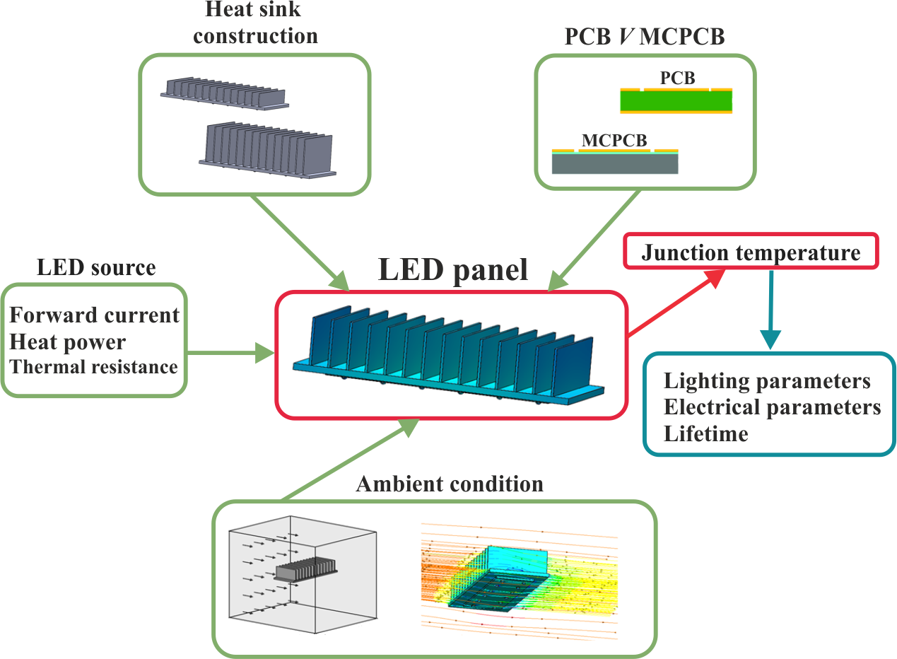
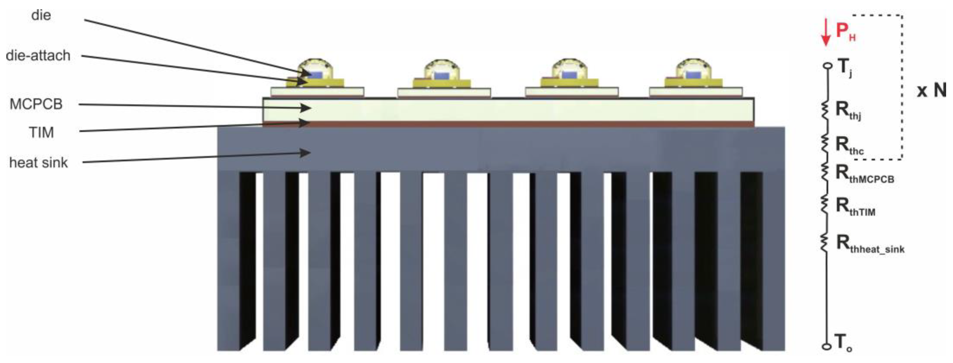
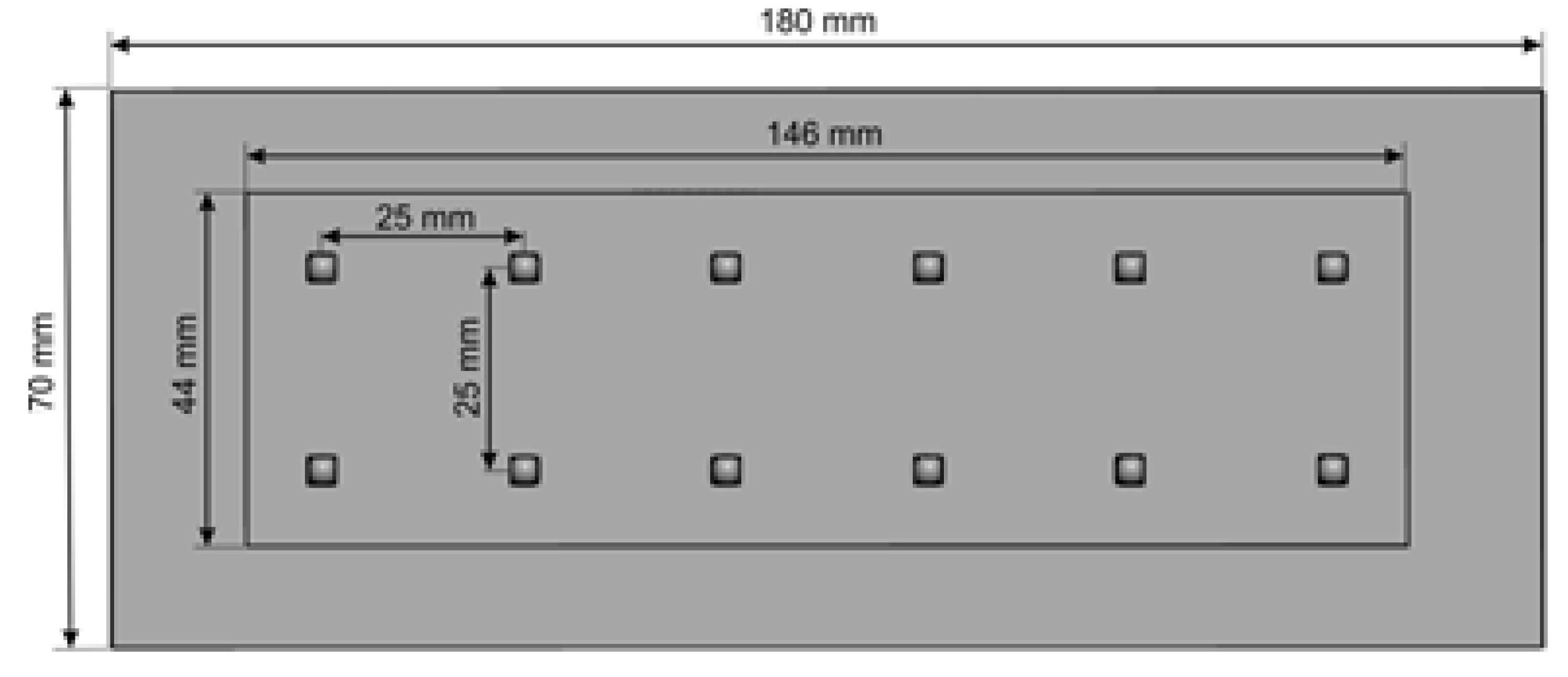
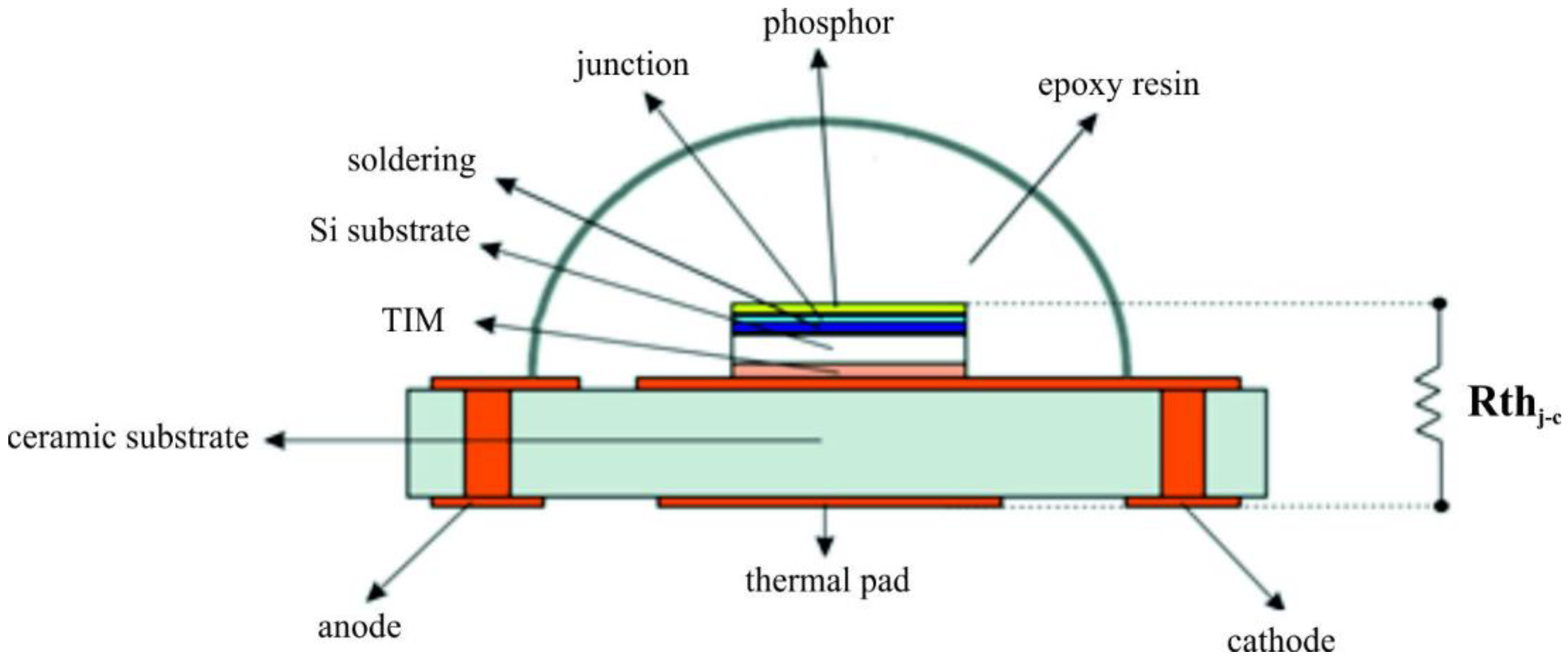
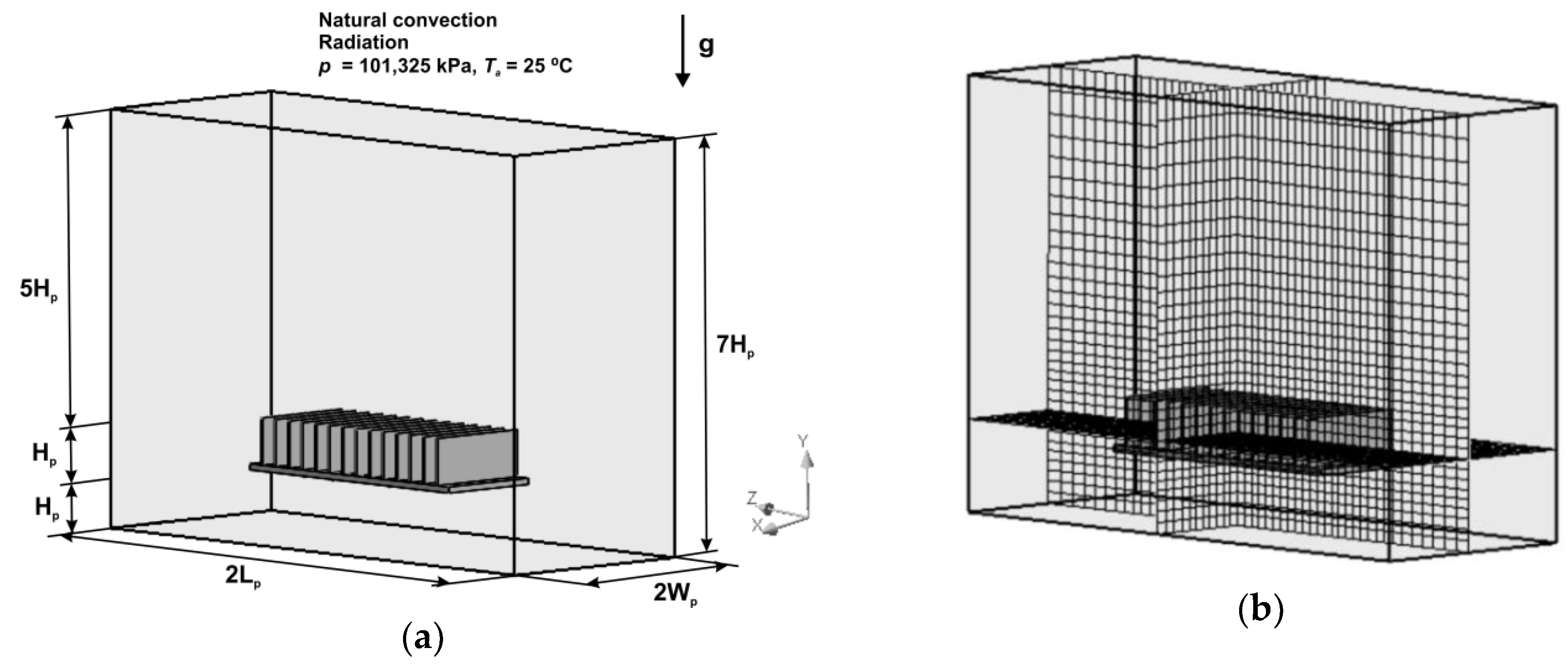
2. LED Panel Thermal Model

Numerical studies were done using a specialized simulation tool—FloEFD® 16.2 of the Mentor Graphics company. The selected option includes, among others, an in-built CAD (computer aided design module for creating the analyzed three-dimensional geometry and the flow simulation module, based on computational fluid dynamics, which is used for advanced thermal calculations and considers all types of heat transfer, i.e., conductance, convection and radiation [23,24,25].
The computational fluid dynamics (CFD) software is based on solving the Navier–Stokes formula, which encompasses expressions of the conservation laws for mass, momentum and energy of fluid flows [26,27]:
ρ t + x i ( ρ u i ) = 0 ,
ρ u i t + x j ( ρ u i u j ) + ρ x i = x j ( τ i j + τ i j R ) + S i ,   i = 1 ,   2 ,   3 ,
ρ H t + ρ u i H x i = x i ( u j ( τ i j + τ i j R ) + q i ) + ρ t τ i j R ρ u i x j + ρ ε + S i U i + Q H ,
H = h e + u 2 2 ,  
where: u—fluid velocity, ρ fluid density, Si—mass distributed external force per unit mass due to a porous media resistance, he—thermal enthalpy, QH—heat source or sink per unit volume, τ i k —viscous shear stress tensor, qi—diffusive heat flux, H—total enthalpy and ε —rate-of-strain tensor.
The junction temperature of the LED panel sources depends on the number of N installed sources, on their thermal power Ph, total thermal resistance Rthtotal and environmental conditions. The total thermal resistance includes the LED source resistance (Rthj-c), the resistance of the material connecting the LED sources with the MCPCB circuit (RthTIM, thermal interface material), the printed circuit resistance (RthMCPCB) and the heat sink resistance (Rthheat_sink). The value of the above resistances depends on the design of individual elements, their geometry and thermal parameters of the materials used. The components of the thermal resistance of the LED panel are shown in Figure 1.
The article presents the results of research related to the impact of the main factors affecting the temperature of the LED panel associated with the design of the heat sink, printed circuit and the impact of environmental conditions.
For specific thermal studies a panel with 12 LED sources of high power, placed in two rows with six sources in each row was assumed. The size of the LED sources used for the study was 3.45 mm × 3.45 mm × 2.46 mm. The maximum forward current and junction temperature declared in the datasheet are If = 2A and Tj = 150 °C. The sources were installed on the MCPCB (metal core printed circuit substrate) substrate, in the distance of 25 mm from each other. This is a common configuration for placing LED sources in available lens systems [28]. The aforementioned number of sources allows for the total power of 10–40 W, enabling use in both indoor and outdoor lighting. The panels can be combined with each other for higher total power and the required luminous flux value. The size of the printed circuit MCPCB board was 146 mm × 44 mm, whereas the radiator substrate was 180 mm × 70 mm (Figure 2).
In order to provide a reliable thermal analysis it is necessary to determine real thermal power PH of the LED panel sources. This power is directly connected with optical efficiency ηo and it is defined by the formula:
P H = ( 1 η o ) · P e ,
where: PH—heat power, ηo—optical efficiency and Pe—electrical power.
Currently, in many references the optical efficiency of LED sources ηo is declared to be at the level of 15–35% [29,30,31,32,33,34]; one can, however, encounter certain references where the efficiency ηo is a bit higher, reaching up to 45%, depending on the LED source model and IF forward current used [35].
Thermal power PH was determined in a laboratory for the applied LED source. The study was performed at a test stand of the GL Optic company (Figure 3), the content of which consisted of an integrating sphere of the diameter of 500 mm [36], a GL Spectis 6.0 spectrometer [37], a programmable TDK-Lambda GENH300-2.5 DC power supply, as well as a Peltier module with a temperature control knob 5305 TECSource of the Arroyo Instruments company [38].
The LED source was installed on the surface of the Peltier module, on which the given temperature Tp was determined. The measurements were done for four given temperatures Tp: 25; 45; 65; 85 °C, as well as for three values of forward currents: IF: 350; 700 and 1050 mA.
The research results are presented in Table 1.
The essence of a reliable thermal analysis of a panel with LED sources based on the CFD method is good knowledge of material structure of a semi-conductive light source. Additionally, modeling must also take into consideration accurate representation of the geometry of all material layers forming the content of the LED source, as well as correctly defined physical and thermal parameters. The method of thermal modeling of semi-conductive light sources is burdened with significant difficulties connected with accurate reconstruction of the material structure and parameterizing the semi-conductive junction, which is connected with trade secrets, thus a difficulty to obtain data concerning LED source structure.
Figure 4 presents a typical structure of a semi-conductive light source of high power, which, because of the conversion of blue light by application of luminophore, emits white light [39].
With regard to the aforementioned difficulties with replicating the LED source structure, a temperature model based on the value of thermal resistance between junction and fitting Rthj-c (Figure 4) is applied for detailed thermal studies [40,41,42]. The selected thermal model was defined and presented in an international standard—JEDEC JESD15-3 Two-resistor compact thermal model guideline [43]. It may be implemented and applied in three dimensional simulation tools, also in CFD.
The method of measuring internal thermal resistance Rthj-c that has also application in the case of semi-conductive light sources was described, among others, in JESD51-14 ‘Transient Dual Interface Test Method for the Measurement of the Thermal Resistance Junction-to-Case of Semiconductor Devices with Heat Flow Through a Single Path’ [44] and JESD51-51 ‘Implementation of the Electrical Test Method for the Measurement of Real Thermal Resistance and Impedance of Light-Emitting Diodes with Ex-posed Cooling’ [45].
The measuring method described in JESD51-14 implies double measurement of the transient cooling curve of the same LED source that differs with regard to the coefficient of heat conduction k of the heat conductive material between LED source and a radiator. Application of two materials of different coefficients k enables to read the point of ‘diverging the curves’ of cooling, which enables to determine thermal resistance Rthj-c.
Slightly different manner of installing LED sources that enables to register a characteristic point of ‘diverging’ the curves of cooling was assumed in the study. Two analogous LED sources were soldered to two identical boards of the MCPCB printed circuit [46] in two ways—the first diode was soldered with all pads (two electric and one thermal), whereas the second one was soldered with electric pads only, without thermal pads (Figure 5).
The above described method of installation enables to determine the point of ‘diverging’ the cooling curves in the point of changing the direction of heat flow from junction through MCPCB substrate to the environment [32,33].
The measurements of thermal resistance Rthj-c of the studied LED sources were done by means of a T3Ster transient thermal tester of the Mentor Graphics company [47], which enables measurements compliant with the international JEDEC JC-1 standard.
Measurements of the internal thermal resistance Rthj-c of the studied LED source was done for three conduction currents: IF: 350 mA, 700 mA and 1050 mA.
A chart of the cumulative functional structure of the studied LED source is presented in Figure 6.
The solid line designates the curves for the LED source with all pads soldered, whereas the dashed line for no thermal pad soldered. The point of ‘diverging’ the lines, projected on the axis of cumulative thermal resistance indicates the value of the searched thermal resistance Rthj-c between the junction and the LED source fitting. The value of thermal resistance Rthj-c for currents IF = 350 mA and IF = 700 mA achieved the same value of Rthj-c = 8.6 °C/W, while in the case of IF = 1050 mA this value was slightly higher and amounted 8.8 °C/W.
A 3D view of the studied 6 × 2 LED panel, together with marked material structure is presented in Figure 7, while the parameters of the applied materials and their physical properties are presented in Table 2.
The thermal power PH determined in an experimental way and thermal resistance Rthj-c became the basis of the developed thermal model of the LED panel. The presented model (Figure 7, Table 2) became the basis for specific studies connected with the influence of radiator construction, the applied printed circuit and ambient conditions on junction temperature of the installed LED sources.

3. Thermal Analysis of LED Panel Elements

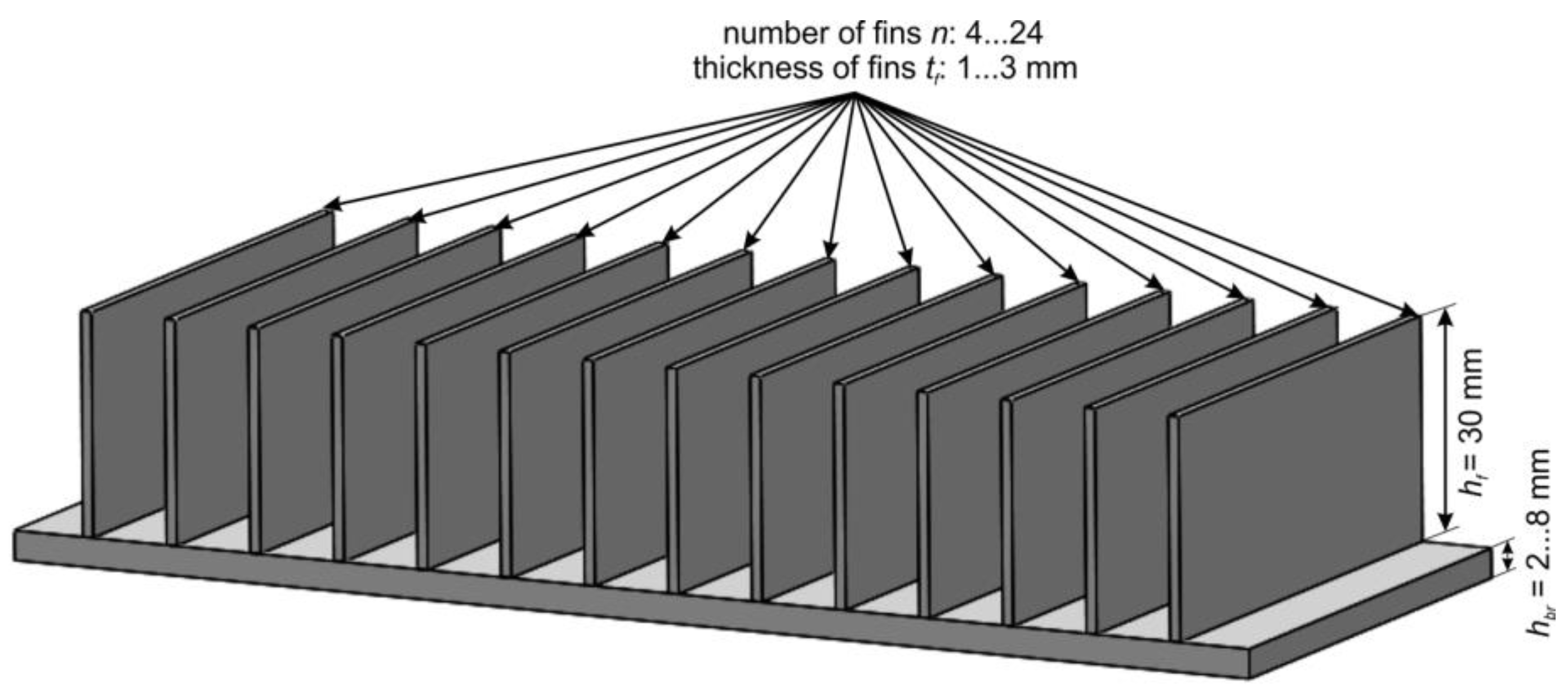
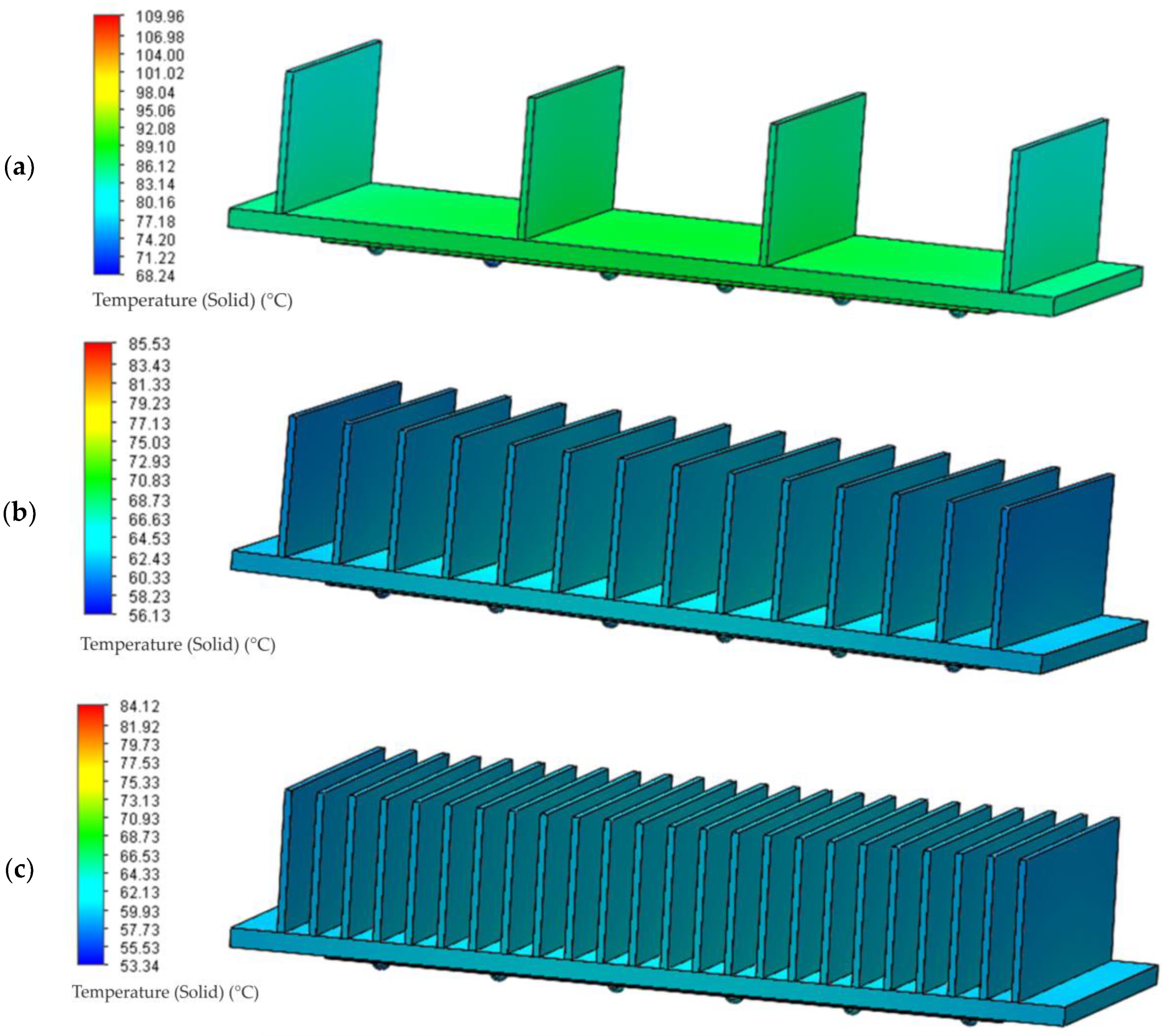
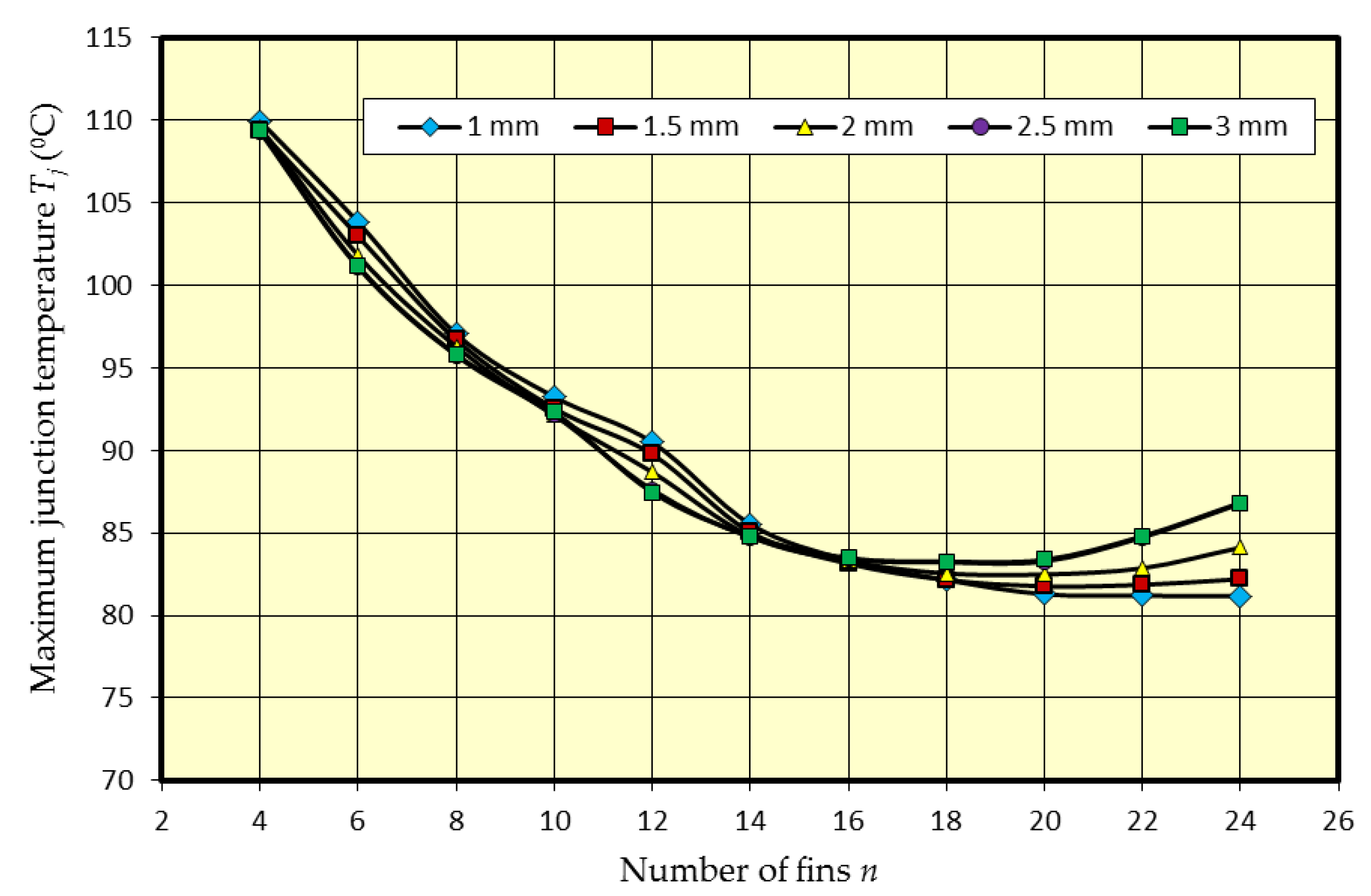
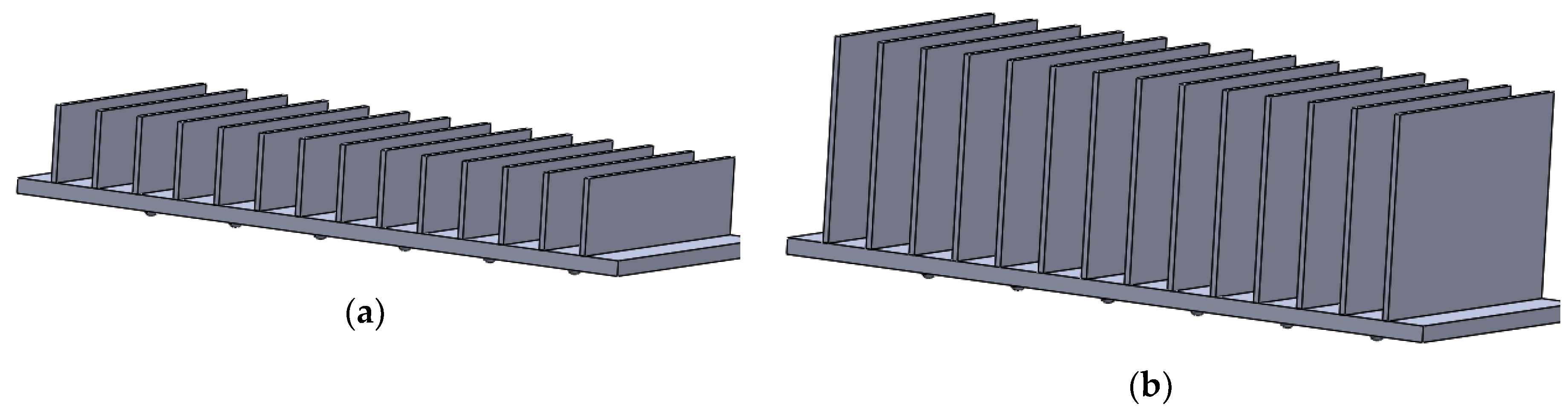
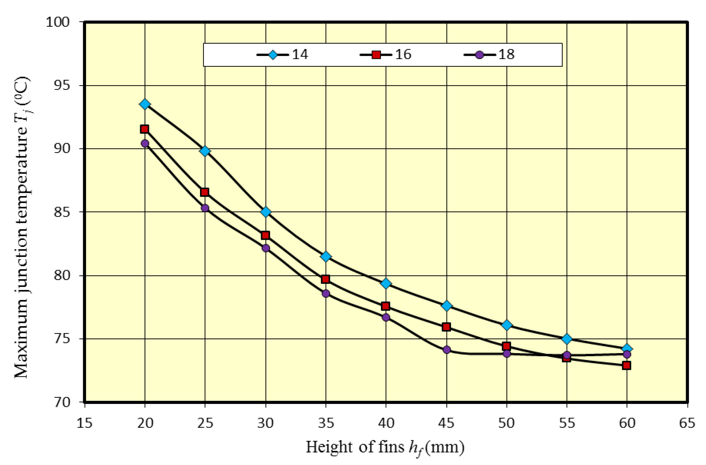
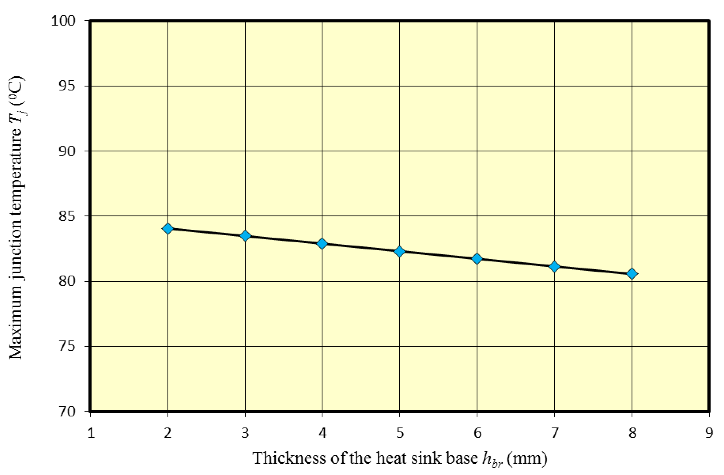
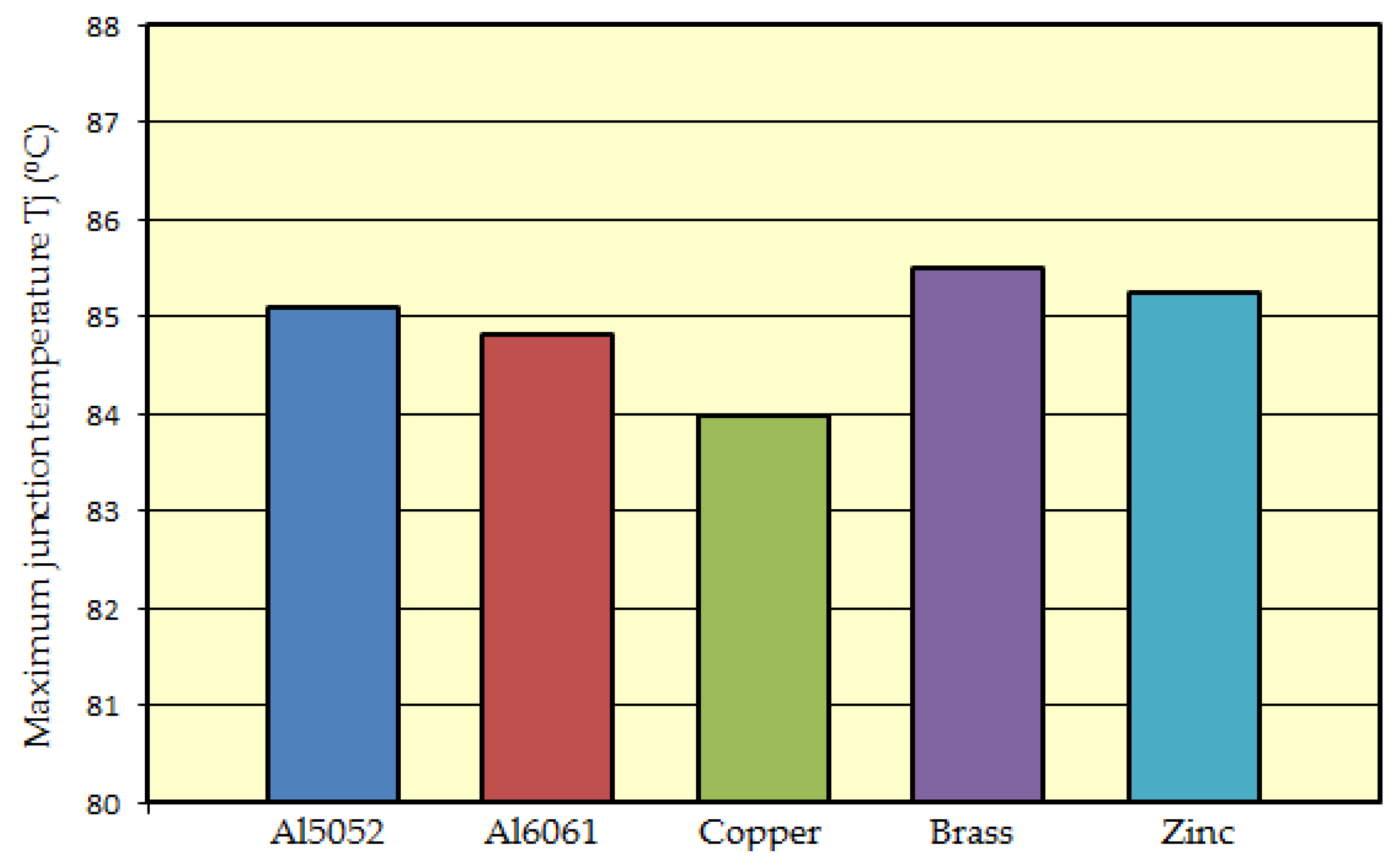
3.1. Influence of Radiator Construction

A thermal model of a 2 × 6 LED panel (Figure 2 and Figure 7), as well as designated parameters of the LED source (Table 1 and Table 2) were assumed in the study. Simulations were done for the maximum investigated value of the conduction current IF = 1050 mA and the corresponding thermal power PH. For the abovementioned value of IF the highest values of thermal power PH and thermal resistance Rthj-c were designated, which corresponds to the most unfavorable thermal conditions. Thermal parameters of the model were specified in Table 2. In order to determine the influence on junction temperature Tj by the number of radiator fins n and the resultant distance between them df, it was assumed in the initial phase that the radiator has four fins, and then this number was being increased to twenty four, with a two fin step. The height of fins hf was constant and amounted 30 mm, whereas fin thickness tf was changed in the range of 1–3 mm, with a step of 0.5 mm (Figure 8).
The size of computation domain was selected on the basis of considering the characteristics of heat transfer and computation time. The domain size was set as 7Hp, the width and length of the computation domain as 2Wp and 2Lp, where Hp, Wp and Lp designate, respectively, height, width and length of the LED panel (Figure 9a). In the simulation studies the natural convection was assumed as boundary conditions. The air pressure surrounding the panel was p = 101,325 kPa and the ambient temperature was Ta = 25 °C. Thermal radiation was considered in simulation computations, the emission coefficient ε for an aluminum board was 0.2. Gravitation acceleration was assumed as g = 9.81 m/s2, contrary to the direction of the Y axis.
The computation grid was defined by using an advanced module for creating adaptive numerical grid, which was in-built in the FloEFD software 16.2. Cross section of the numerical grid along every axis of XYZ was presented in Figure 9b.
Temperature distribution for the LED panel with a radiator equipped in 4, 14 and 24 fins of the thickness of tf = 2 mm and height hf = 30 mm is presented in Figure 10.
In the case of the radiator with four fins the maximum value of junction Tj of the LED panel installed sources amounted the value of almost 110 °C. In the case of the radiator with 14 fins the maximum value of the junction temperature Tj amounted 85.5 °C, which comprised a decrease of the value of about 23% in relation to a radiator with four fins. The decrease of temperature Tj results from a radiator area increased by additional fins, the consequence of which has bigger summary heat capacity of the radiator Cp. Increasing the number of fins with another 10 ones, up to 24 did not contribute to a significant change in comparison to a radiator with 14 fins. The maximum junction temperature Tj in the abovementioned case was lower by only 2 °C and amounted, respectively, 84.1 °C. The influence of the number of radiator fins n of different thickness on the maximum junction temperature Tj of the installed LED panel sources was presented in Figure 11.
The number of fins n as well as the distance df between them was considered for constant dimensions of the radiator substrate (Figure 8). In the initial phase increasing the summary number of radiator fins to 14 resulted in, virtually, a linear decrease of the maximum junction temperature Tj. In the aforementioned range increasing the number of fins by a consecutive of 2 caused a decrease of the maximum temperature Tj of, on average, 5% in the case of all the studied fin thicknesses tf. An increase of the summary number of radiator fins from 14 to 16 resulted in an insignificant decrease of the junction temperature value Tj, while a further increase of the number of fins did not cause a decrease of temperature Tj. For a fin thickness of 2, 2.5 and 3 mm it resulted in an increase of junction temperature Tj. On the basis of the results of simulation studies it is possible to state that increasing the number of radiator fins n has an influence on decreasing the temperature value Tj up to a certain boundary number of fins. Installing additional fins over this number does not influence the increase of the conditions of thermal sources, and may even deteriorate them. It is connected with small space between fins and hindered conditions of convective heat reception in this heat sink part.
In the case of the analyzed LED panel radiator (Figure 8) it may be assumed that the effective number of fins n that ensures right thermal conditions of LED sources functioning is in the range from fourteen to eighteen. The influence of fin height on junction temperature Tj of the installed LED sources was studied in simulations for the aforementioned range connected with effective number of radiator fins. The height of radiator fins hf was changed only in the range from 20 to 60 mm, with a 5 mm step, while their thickness was constant tf = 1.5 mm. Figure 12 presents a model of a balanced radiator for two extreme fin heights, and the influence of radiator fin height on the maximum junction temperature Tj of the installed LED sources is presented in Figure 13.
The highest value of junction temperature Tj of LED sources was determined for the lowest fin height that was hf = 20 mm. Together with a gradual increase of fin height of 5 mm the temperature Tj was decreasing, which is connected with bigger summary radiator area and its increased heat capacity Cp. Average temperature drop Tj was about 5% when increasing the height to 35 mm. Above this value the drop of maximum temperature Tj was smaller and amounted about 2%. For a radiator with 18 fins the increase of fin height from 45 to 60 mm did not influence the decrease of the value of junction temperature of the LED source, which is indicative to obtaining the boundary value of radiator area, increasing of which does not contribute to, in a significant degree, to temperature operation conditions of LED sources and junction temperature Tj.
The next step connected with a thermal study of heat sink construction was determining the influence of radiator base thickness hbr on temperature working conditions of semi-conductor light sources. A radiator with 14 identical fins of the height hf amounting 30 mm and thickness of tf = 1.5 mm was modeled for the studies, which resulted from results of previous simulation studies. The radiator substrate thickness hbr was alternated in the range from 2 to 8 mm, with a 1 mm step. Working conditions of light sources and boundary conditions of the LED panel were defined in an analogous way to previous studies connected with the influence of the number and height of the studied radiator fins. The influence of radiator substrate thickness on the maximum junction temperature Tj of the installed light sources was presented in Figure 14.
The highest value of junction temperature Tj of 83.9 °C was determined for heat sink substrate thickness hbr = 2 mm. Together with the increase of radiator substrate thickness, a slight influence on maximum temperature Tj of the installed LED sources was observed. The increase in the thickness of the heat sink base 2 to 8 mm resulted in reduction of the junction temperature of approx. 4%.
The next point of studies connected with the influence of radiator construction on heat distribution of the LED panel was determining the influence of the material of which it was made. The most frequently used material for production of radiators is aluminum, which is characterized by a relatively high value of thermal conductivity k, low weight and acceptable production cost. The most frequent aluminum alloy used in production of radiators is AL5052, the doping of which is mainly magnesium and chromium, as well as aluminum alloy Al6061, doped mainly with silicon, iron and magnesium. A popular material of good thermal parameters used to produce radiators is copper. It is characterized by a high thermal conductivity coefficient k, but a relatively high density ρ (over three times greater than of aluminum) and relatively high production cost cause copper radiators to be used in special applications and situations, when radiators made of aluminum alloys cannot be applied. Other materials that may be encountered in production of radiators are zinc and a zinc alloy—brass.
A heat sink with fourteen fins of the height hf = 30 mm and thickness tf = 1.5 mm was adopted for the tests, which resulted from the results of previous simulation studies. The study was performed for five radiator materials, the basic parameters of which are presented in Table 3.
Figure 15 presents maximum junction temperature Tj of the installed light sources in the conditions stated in relation to radiator material.
On the basis of the obtained results it may be stated that radiator material did not influence significantly heat distribution of the LED panel, as well as junction temperature of the installed light sources. The lowest junction temperature Tj = 84 °C was determined for a radiator made of copper. For a radiator made of brass, the heat conductivity coefficient k of which is almost four times lower in relation to copper, the maximum junction temperature Tj was higher by only 1.5 °C in relation to a copper radiator and comprised an increase of less than 2%. For the LED panel with a radiator made of aluminum alloy, both Al5052 as well as Al6061, maximum junction temperature Tj was similar and amounted 85 °C.

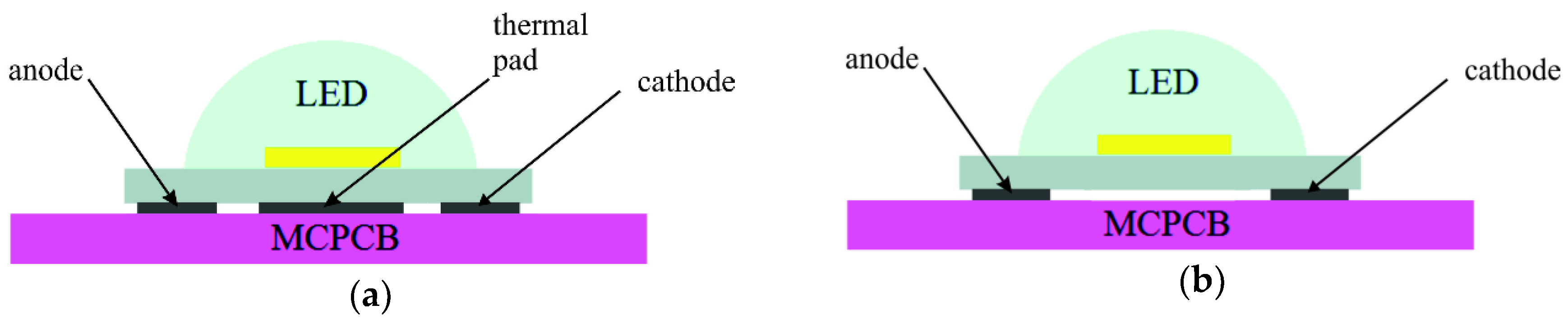
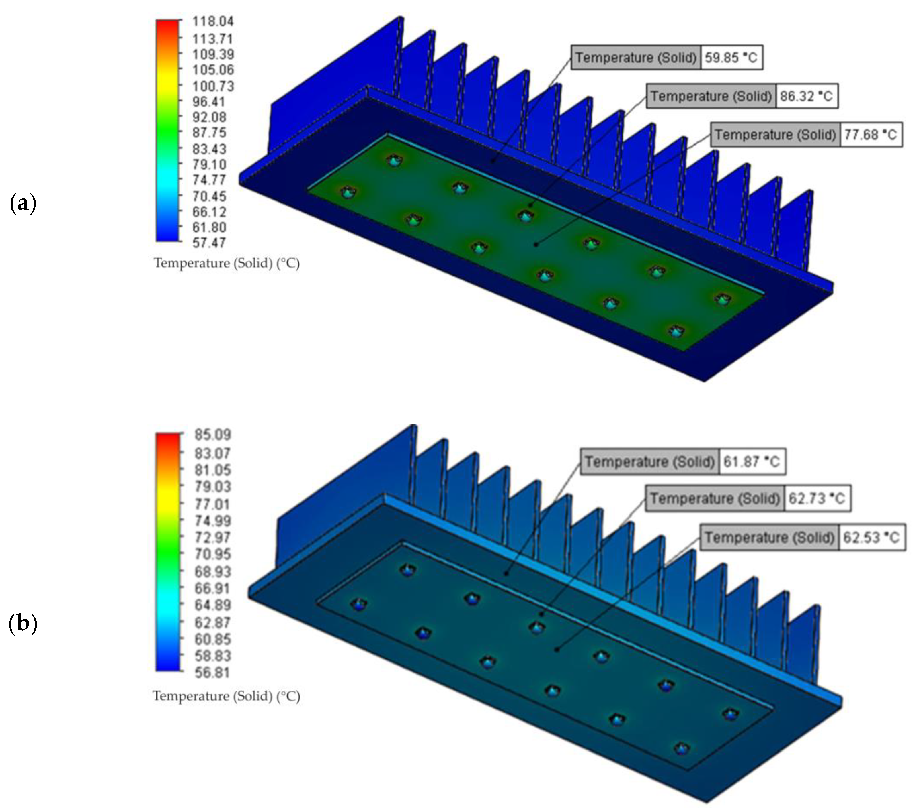
3.2. Influence of the Printed Circuit (FR4 v MCPCB)

Semi-conductor light sources are installed on boards of printed circuits, enabling, thus, voltage feed and polarization in the direction of conduction. Mounting on a printed circuit board also enables configuration of LED panels comprised of a dozen or so, several dozens or even several hundreds of semi-conductor light sources. The heat generated by semi-conductor light sources PH is conducted, in the first place, to the printed circuit in order to get to the radiator through a connective layer, where it is removed to the environment in the convective manner. The possibility of fast heat reception by the printed circuit board and further effective transfer of it to the radiator has a significant importance in the context of heat transfer of semi-conductor light sources, which allows for effective working conditions of LED sources.
Currently two technological solutions connected with the production of printed circuits may be encountered, i.e., circuits with a glass-epoxy laminate FR4 (printed circuit board—PCB), and circuits with a metal core (metal core printed circuit board—MCPCB) [49]. Printed circuit boards on the glass-epoxy based laminate FR4 are made of upper copper layer that comprises conductive paths, dielectric layer that is most often glass fiber with epoxy resin (FR4) and a lower layer of copper. Circuits on the basis of glass-epoxy laminate FR4 are characterized by a relatively simple manufacturing technology and low production costs, due to which they have a wide application in electronic systems. A drawback of PCB circuits is, however, having a low value of heat conductivity, connected with a high value of thermal resistance of the applied laminate FR4. The consequence of that are problems with application of PCB circuits in high power electronic systems, which is connected with the difficulty in removing heat from those systems.
Metal core printed circuit boards (MCPCB) are characterized by better thermal properties. Their basis comprises of a metal core, which is most often aluminum alloy and less often copper or steel. On the metal core there is a relatively thin dielectric layer of thermal conductivity much higher than in the case of a glass-epoxy laminate FR4. The upper layer consists of copper conductive paths of standardized thickness. Thermal conductivity of MCPCB circuits is significantly higher in relation to PCB circuits, which is connected with application of a thinner layer of dielectric material of significantly higher thermal parameters.
In the case of high power semi-conductor light sources, where effective heat removal from semi-conductor junction has significant importance in the context of correct operation of LED sources, metal core printed circuit boards (MCPCB) are used in most cases. Significantly better thermal parameters of the aforementioned circuits in comparison to glass-epoxy based laminate FR4 cause that heat from LED sources is received in a more effective way, and then transferred to the radiator. In Figure 16a typical structure of PCB and MCPCB printed boards is presented, and in Table 4 there are four exemplary thicknesses of layers with their respective coefficients of thermal conductivity.
Figure 17 presents results of heat distribution of the LED panel, where LED sources were installed on a printed circuit with glass-epoxy laminate FR4, as well as on a metal core circuit. In the case of applying PCB substrate the junction temperature Tj of the installed LED sources was over 118 °C. What is characteristic in this case is a high (amounting over 20 °C) temperature gradient between upper PCB substrate side and the radiator, which is connected with low thermal conductivity of the substrate and the difficulty in effective heat removal to the radiator. The PCB substrate is also characterized by uneven temperature distribution on its surface. In close proximity to the installed LED sources the temperature on the PCB surface is on average 10 °C higher in relation to the middle part of the printed circuit.
Application of the MCPCB substrate improved, in a significant way, thermal conditions of the operation of LED panel semi-conductor light sources. Maximum temperature of the junction Tj was in this case 85 °C and it was 33 °C lower in relation to LED sources of the substrate installed on the PCB, which comprised a decrease of 28%. Heat distribution on the MCPCB substrate was even, and the temperature gradient between the upper substrate part and radiator was insignificant, which proved good heat removal to the heat sink.

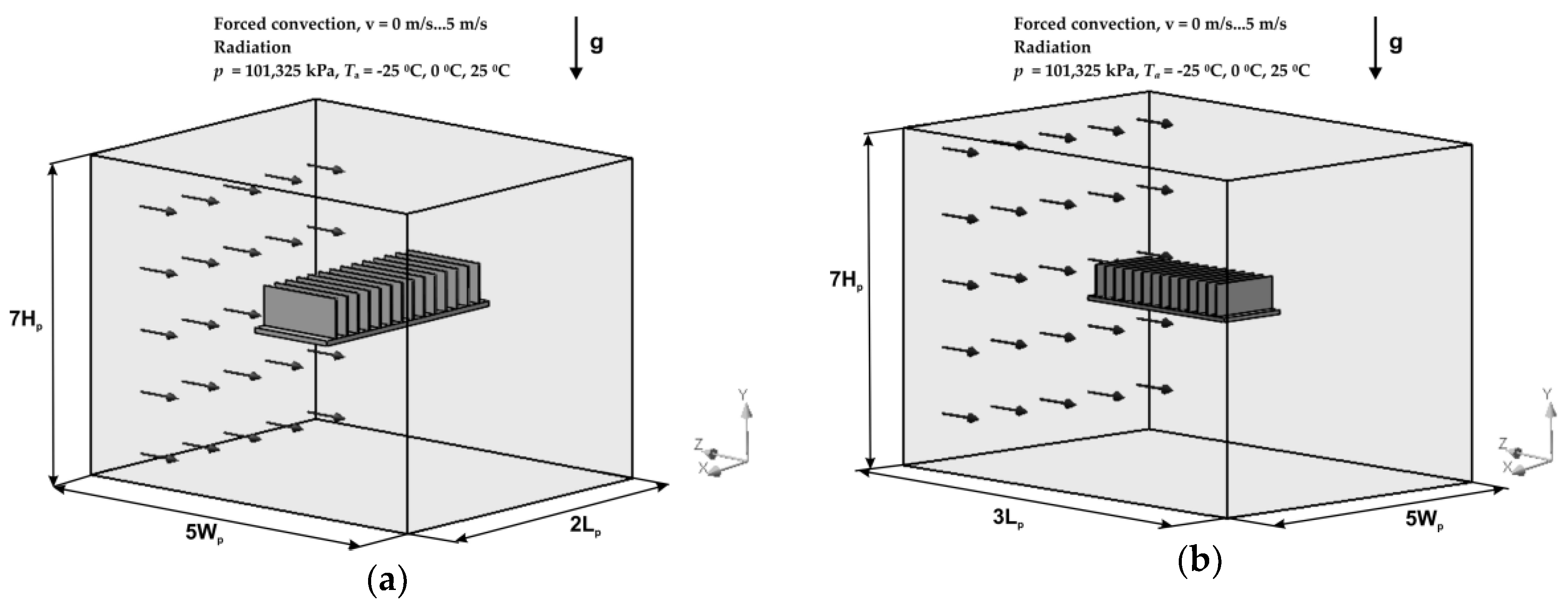
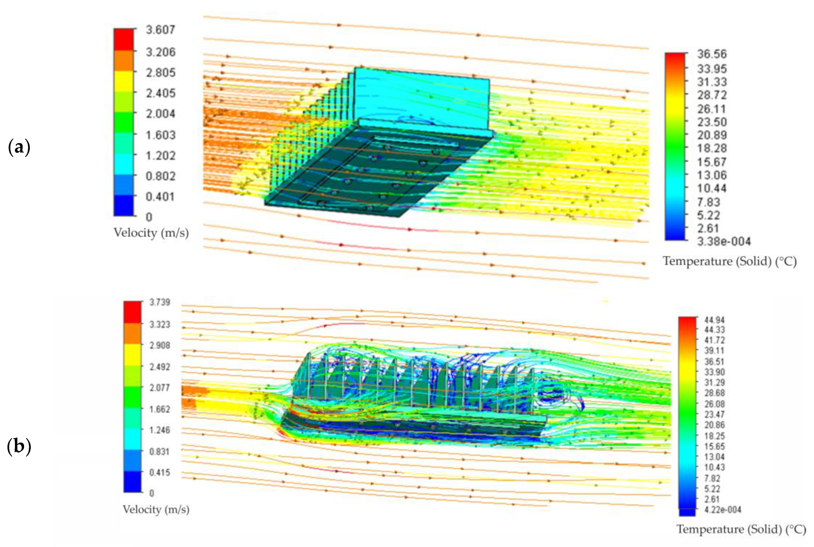
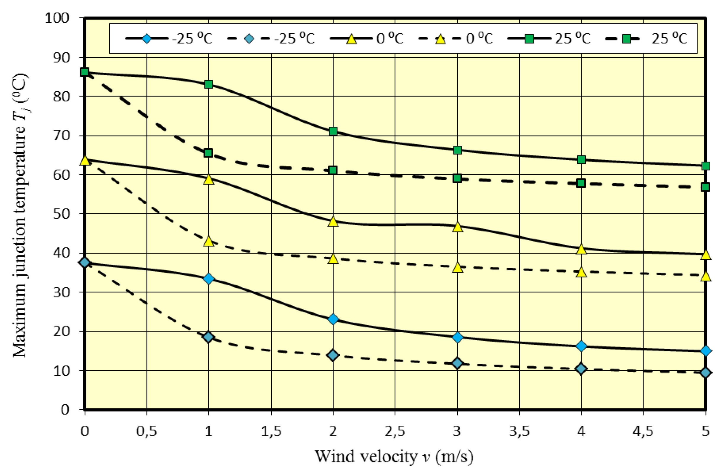
3.3. The Influence of Ambient Conditions

Semi-conductor light sources often operate in specific ambient conditions that influence operation conditions of LED sources. An example of that are road light fittings that operate in changing ambient conditions, where both seasonal, monthly, as well as daily temperature of ambience may be in a very wide range from −30 to 45 °C [4].
Another ambient factor affecting thermal operation conditions of fittings with semi-conductor light sources is wind. Natural airflow may support heat transfer between the fitting and semi-conductor light sources and the ambience. Appropriate construction of the fitting frame, as well as the radiator that enables airflow may in a natural way contribute to improvement of thermal operation conditions of LED sources.
In this context simulation studies were performed, which were connected with the influence of ambient temperature Ta and the speed of airflow v on temperature distribution and maximum junction temperature Tj of LED panel sources. The studies were performed for an analogous LED panel that was used in previous simulations. The studies were performed for three values of ambient temperature Ta (−25; 0 and 25 °C) as well as the forced airflow in the range from 0 to 5 m/s. Additionally, the direction of airflow was set in two ways: directly on the radiator and on its side, as presented in Figure 18.
Temperature distribution of the LED panel, as well as trajectories of airflow for selected external conditions (Ta = 0 °C, v = 3 m/s) were presented in Figure 19. For forced airflow in the radiator’s lateral direction the maximum temperature of junction Tj was 36.5 °C, while for the flow in radiator frontal direction the temperature was 23% higher and reached the value of almost 45 °C. Lower temperature of junction Tj of LED panel sources, in which the airflow was in the radiator’s lateral direction, is connected with more effective airflow, which goes around radiator fins, contributing to improvement of the LED panel thermal conditions. In the case of airflow in the direction in front of the radiator the air particles have an interrupted way, hitting radiator fins, which is presented in detail in Figure 18b.
The influence of ambient temperature Ta and wind speed v on maximum junction temperature Tj of LED panel sources was illustrated in Figure 20. The results were presented for three ambient temperature values Ta = −25; 0; 25 °C, as well as for two airflow directions. Junction temperature Tj for the case in which the airflow was in the radiator’s lateral direction (Figure 18a) was marked with a dashed line, while for the direction in front of the radiator (Figure 18b) it was marked with a solid line. Wind speed varied in the range from 0 to 5 m/s.
In the case of free convection (v = 0 m/s) increasing ambient temperature Ta to the value of 25 °C resulted in an analogous increase of junction temperature Tj. For forced airflow (v = 1–5 m/s) the temperature increase Tj was similar to the increase of ambient temperature Ta.
On the basis of the results it may be stated that even relatively low wind speed (up to 2 m/s) improved in a significant way the temperature operation conditions of LED panel sources. For wind speed of 1 m/s the junction temperature Tj for lateral airflow direction decreased, on average, for all three ambient temperatures of about 20 °C. In the case of frontal airflow, for the wind speed of 1 m/s the decrease of junction temperature Tj was in the range of 4 °C. However, with further increase of wind speed to 2 m/s, junction temperature Tj was on average about 15 °C lower. Further increase of wind speed to 5 m/s resulted in further reduction of the value of junction temperature Tj, but the dynamics of the temperature value decrease Tj was, to a significant degree, lower than in the range of wind speed changes up to 2 m/s.
The obtained research results prove that even a low value of wind speed reaching up to 2 m/s may, to a significant degree, improve temperature operation conditions of LED panel sources. At the above wind speed, the junction temperature was lower by approx. 30% compared to natural convection. In the aforementioned range of wind speed the biggest drop in junction temperature Tj was observed. Further increase of wind speed affected the temperature operation conditions of LED sources to a lower degree. For wind speed of 5 m/s the junction temperature Tj of LED sources did not, virtually, change its value, in relation to the wind speed of 4 m/s. It can be assumed then that further increase of wind speed would not influence temperature operation conditions of semi-conductor light sources.

4. Conclusions

The determined value of heat power PH and thermal resistance Rthj-c was the basis of the developed thermal model of the LED panel. The model was implemented in the FloEFD software based on computational fluid dynamics. Efficient operation of the LED panel is connected with providing appropriate thermal conditions that enable optimal operation of semi-conductor light sources. Junction temperature Tj of semi-conductor light sources that comprises a LED panel is dependent on many factors, which include mainly: PH power of every LED source, the number of installed sources, their configuration and distances between them. The next important aspect of thermal analysis is the evaluation of the radiator system operation, MCPCB substrate and determining their influence on junction temperature Tj of the installed light sources. The analysis should also consider the influence of ambient conditions, such as ambient temperature Ta or natural or forced airflow.
The conducted simulation studies indicated a significant influence of the aforementioned factors on the temperature value of the installed LED panel light sources. The simulation studies connected with radiator construction confirmed its influence on shaping LED panel temperature distribution. An increase of radiator fins that resulted in an increase of radiator heat capacity Cp translated into improvement of thermal conditions, up to a certain boundary value of fins, above which there occurred deterioration of heat removal conditions. For the analyzed system, the number of fins in the range from fourteen to eighteen provided most effective conditions of heat removal from semi-conductor light sources. A similar dependency was determined for the change of radiator fins, where an increase over certain boundary value did no translate into improvement of thermal operation conditions of LED sources. A change in radiator substrate thickness, as well as the material of which it was made, did not significantly influence heat distribution of the LED panel.
The analysis and thermal studies of the available technologies of printed circuit boards confirmed better temperature operation conditions of LED sources in the case of applying technologies with MCPCB metal core. Junction temperature Tj in this case was 85 °C, while applying PCB substrate PCB with FR4 laminate resulted in an increase of temperature Tj of LED sources to the value of 118 °C.
The performed studies indicated significant usefulness of natural airflows in improving temperature operation conditions of LED sources. In the analyzed LED panel-radiator system, lateral airflow of the speed of 1 m/s led to a drop of temperature Tj of the sources of over 20%. In the case of airflow direction in front of the radiator, the drop of temperature value Tj amounted 17% for the wind speed of 2 m/s. The research studies indicated that relatively small wind speed reaching up to 2 m/s enables significant improvement of temperature operation conditions of light sources, which can be used in construction of light fittings for more effective cooling of semi-conductor light sources.

Author Contributions

Measurements of LED source parameters were made by H.W. The results of simulation studies presented in this manuscript and their assessment was carried out by K.B. and A.R. Finally, S.R. and D.M. supervised the research and prepared the manuscript.

Funding

This research received no external funding.

Conflicts of Interest

The authors declare no conflict of interest.

References

  1. Byung-Lip, A.; Ji-Woo, P.; Seunghwan, Y.; Jonghun, K.; Seung-Bok, L.; Cheol-Yong, J. Savings in Cooling Energy with a Thermal Management System for LED Lighting in Office Buildings. Energies 2015, 8, 6658–6671. [Google Scholar] [Green Version]
  2. Jagerbrand, A. LED (Light-Emitting Diode) Road Lighting in Practice: An Evaluation of Compliance with Regulations and Improvements for Further Energy Savings. Energies 2016, 9, 357. [Google Scholar] [CrossRef]
  3. Barroso, A.; Dupuis, P.; Alonso, C.; Jammes, B.; Seguier, L.; Zissis, G. A characterization framework to optimize LED luminaire’s luminous efficacy. In Proceedings of the 2015 IEEE Industry Applications Society Annual Meeting, Addison, TX, USA, 18–22 October 2015; pp. 905–913. [Google Scholar]
  4. Lasance, C.; Poppe, A. Thermal Management for LED Applications; Springer Science, Business Media: New York, NY, USA, 2014. [Google Scholar]
  5. Leśko, M.; Baran, K.; Wachta, H.; Różowicz, A. A Concept of an Adaptive Luminaire with Variable Luminous Intensity Distribution. In Proceedings of the 2018 VII. Lighting Conference of the Visegrad Countries (Lumen V4), Trebic, Czech Republic, 18–20 September 2018; pp. 1–4. [Google Scholar]
  6. Khanh, T.; Bodrogi, P.; Vinh, Q.; Winkle, H. LED Lighting. Technology and Perception; Wiley-VCH Verlag GmbH: Darmstadt, Germany, 2015. [Google Scholar]
  7. Yang, K.; Chung, C.; Tu, C.; Wong, C.; Yang, T.; Lee, M. Thermal spreading resistance characteristics of a high power light emitting diode module. Appl. Ther. Eng. 2014, 70, 361–368. [Google Scholar] [CrossRef]
  8. Bridges, J. Extend the life of LEDs through thermal design. LEDs Magazine, 2015; 84–86. [Google Scholar]
  9. Chajed, S.; Xi, Y.; Li, Y.; Gessmann, T.; Schubert, E. Influence of junction temperature on chromaticity and color-rendering properties of trichromatic white-light sources based on light-emitting diodes. J. Appl. Phys. 2005, 97, 39–42. [Google Scholar]
  10. Oleksy, M.; Kraśniewski, J.; Janke, W. Wpływ temperatury na charakterystyki optyczne i elektryczne diod LED mocy. Przegląd Elektrotechniczny 2014, 9, 83–85. (In Polish) [Google Scholar]
  11. Ahn, B.; Park, J.; Yoo, S.; Kim, J.; Jeong, H.; Leigh, S.; Jang, C. Synergetic Effect between Lighting Efficiency Enhancement and Building Energy Reduction Using Alternative Thermal Operating System of Indoor LED Lighting. Energies 2015, 8, 8736–8748. [Google Scholar] [CrossRef] [Green Version]
  12. Kudsieh, N.; Khizar, M.; Raja, M.Y.A. Thermal modeling of specialty heat-sinks for low-cost COP packaging of high-power LEDs. In Proceedings of the 2012 IEEE 9th International Conference on High Capacity Optical Networks and Enabling Technologies (HONET), Istanbul, Turkey, 12–14 December 2012. [Google Scholar]
  13. Poppe, A.; Farkas, G.; Gaal, L.; Hantos, G.; Hegedus, J.; Rencz, M. Multi-Domain Modelling of LEDs for Supporting Virtual Prototyping of Luminaires. Energies 2019, 12, 1909. [Google Scholar] [CrossRef]
  14. Tzeng, S.; Jeng, T.; Wang, Y. The cooling Design of a High-Speed Rotating Axis with Ribbed Turbulators. IJETI 2013, 3, 38–48. [Google Scholar]
  15. Shen, Q.; Sun, D.; Xu, Y.; Jin, T.; Zhao, X. Orientation effects on natural convection heat dissipation of rectangular fin heat sinks mounted on LEDs. Int. J. Heat Mass Transf. 2014, 75, 462–469. [Google Scholar] [CrossRef]
  16. Gupta, D.; Venkataraman, V.; Nimje, R. CFD & Thermal Analysis of Heat Sink and its Application in CPU. Int. J. Emerg. Technol. Adv. Eng. 2014, 4, 198–202. [Google Scholar]
  17. Hyunjong, K.; Kyoung, J.; Yeonwon, L. Thermal Performance of Smart Heat Sinks for Cooling High Power LED Modules. In Proceedings of the 13th IEEE Intersociety Conference on Thermal and Thermomechanical Phenomena in Electronic Systems, San Diego, CA, USA, 30 May–1 June 2012. [Google Scholar]
  18. Yieang, H.; Shengnan, S.; Hui, L.; Yunjie, G. Improved thermal design of fin heat sink for high-power LED lamp cooling. In Proceedings of the 17th International Conference on Electronic Packaging Technology, Wuhan, China, 16–19 August 2016; pp. 1069–1074. [Google Scholar]
  19. Cao, J. Study on Three-imensional Numerical Simulation of the Influence of Fin Spacing on the Power of Heat Sink and Heat Dissipation. In Proceedings of the Asia-Pacific Power and Energy Engineering Conference, Wuhan, China, 25–28 March 2011. [Google Scholar]
  20. Min, W.; Seung, W.; Yongchan, K. Optimal thermal design of a horizontal fin heat sink with a modified-opening model mounted on an LED module. Appl. Therm. Eng. 2015, 91, 105–115. [Google Scholar]
  21. Teeba, N.; Anithambigai, P.; Dinash, K.; Mutharasu, D. Influence of the Heat Sink Orientation and Fins Arrangement on the Thermal Behavior of High Power LED. In Proceedings of the 3rd Asia Symposium on Quality Electronic Design, Kuala Lumpur, Malaysia, 19–20 July 2011; pp. 21–24. [Google Scholar]
  22. Rong, W.; Jung, W. Analyzing the structural designs and thermal performance of nonmetal lighting devices of LED bulbs. Int. J. Heat Mass Transf. 2016, 99, 750–761. [Google Scholar]
  23. Sapia, C.; Sozio, G. CFD Transient Model of the Buoyancy Heat Transfer for a Heat Sink: Effects of Geometry Rotation, Thermal Investigations of ICs and Systems (THERMINIC). In Proceedings of the 2012 IEEE 18th International Workshop, Budapest, Hungary, 25–27 September 2012. [Google Scholar]
  24. Chein, R.; Chen, J. Numerical study of the inlet/outlet arrangement effect on microchannel heat sink performance. Int. J. Ther. Sci. 2009, 48, 1627–1638. [Google Scholar] [CrossRef]
  25. Della Torre, A.; Motenegro, G.; Onorati, A.; Khadilkar, S.; Icarelli, R. Multi-Scale CFD Modeling of Plate Heat Exchangers Including O set-Strip Fins and Dimple-Type Turbulators for Automotive Applications. Energies 2019, 12, 2965. [Google Scholar] [CrossRef]
  26. Andersson, B.; Andersson, R.; Hakansson, L.; Mortensen, M.; Sudiyo, R.; Wachem, B. Computational Fluid Dynamics for Engineers; Cambridge University Press: Edinburgh, UK, 2012. [Google Scholar]
  27. FloEFD. Technical Reference, Software Version 16, Mentor Graphics; Mentor Graphics Corporation: Wilsonville, OR, USA, 2016. [Google Scholar]
  28. LEDIL Strada 2x6. Available online: https://www.ledil.com/data/prod/Strada/Strada-IP-2x6-sfds.pdf (accessed on 2 August 2019).
  29. Hsu, H.-C.; Huang, Y.-C. Numerical Simulation and Experimental Validation for the Thermal Analysis of a Compact LED Recessed Downlight with Heat Sink Design. Appl. Sci. 2017, 7, 4. [Google Scholar] [CrossRef]
  30. Guo, Y.; Pan, K.; Ren, G.; Yuan, F. Research on LED Temperature Characteristic and Thermal Analysis at Low Temperatures. In Proceedings of the International Conference on Electronic Packaging Technology & High Density Packaging, Guilin, China, 13–16 August 2012; pp. 1411–1415. [Google Scholar]
  31. Ye, H.; Kohl, S.; Zeijl, H.; Gielen, A. A review of passive thermal management of LED module. J. Semicond. 2011, 32, 014008-1–014008-4. [Google Scholar] [CrossRef]
  32. Poppe, A.; Lasence, C. On the standardization of thermal characterization of LEDs. In Proceedings of the 25th Annual IEEE Semiconductor Thermal Measurement and Management Symposium, San Jose, CA, USA, 15–19 March 2009; pp. 151–158. [Google Scholar]
  33. Pounds, D.; Bonner, R. High heat flux heat pipes embedded in metal core printed circuit boards for LED thermal management. In Proceedings of the 14th Intersociety Conference on Thermal and Thermomechanical Phenomena in Electronic Systems (ITherm), Orlando, FL, USA, 27–30 May 2014; pp. 267–271. [Google Scholar]
  34. Scheepers, G.; Visser, J. Detailed thermal modeling of high powered LEDs. In Proceedings of the 25th Annual IEEE Semiconductor Thermal Measurement and Management Symposium, San Jose, CA, USA, 15–19 March 2009; pp. 87–91. [Google Scholar]
  35. Yurtseven, M.B.; Mete, S.; Onaygil, S. The effects of temperature and driving current on the key parameters of commercially available high-power white LEDs. Lighting Res. Technol. 2016, 48, 943–965. [Google Scholar] [CrossRef]
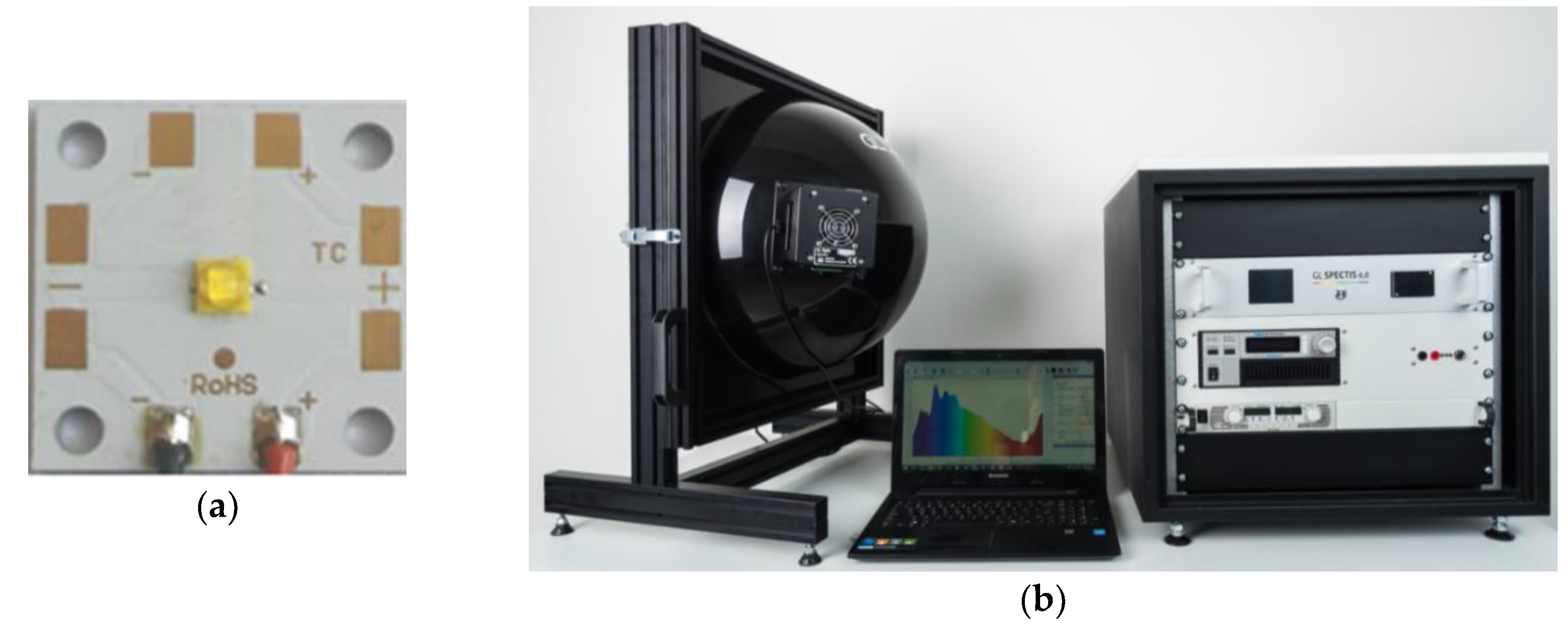
  36. GL Opti Spheres. Available online: http://www.gloptic.com/wpcontent/uploads/2018/08/200931_Technical-Datasheet_SPHEREs.pdf (accessed on 2 August 2019).
  37. GL Spectis 6,0. Available online: http://www.gloptic.com/wp-content/uploads/2018/08/200930_Technical-Datasheet_SPECTIS-6-0.pdf (accessed on 2 August 2019).
  38. 5305 TECSource Arroy Instruments. Available online: http://www.arroyoinstruments.com/products/5305#tabs (accessed on 2 August 2019).
  39. Vakrilov, N.; Stoynova, A.; Kafadarova, N. Application of CFD Modeling to Solve Problems in Thermal Design of LED Applications in the Initial Project Phase. In Proceedings of the 40th International Spring Seminar on Electronics Technology (ISSE), Sofia, Bulgaria, 10–14 May 2017; pp. 1–6. [Google Scholar]
  40. Baran, K.; Wachta, H.; Leśko, M.; Różowicz, A. Research on thermal resistance Rthj-c of high power semiconductor light sources. In Proceedings of the 15th Conference on Computational Technologies in Engineering, AIP Conference Proceedings 2078, Mikolajki, Poland, 16–19 October 2018; p. 020047. [Google Scholar]
  41. Torzewicz, T.; Baran, K.; Raszkowski, T.; Samson, A.; Wachta, H.; Napieralski, A. Compact thermal modelling of power LED light source. In Proceedings of the IEEE 30th International Conference on Microelectronics (MIEL), Nis, Serbia, 9–11 October 2017; pp. 157–160. [Google Scholar]
  42. Torzewicz, T.; Janicki, M.; Napieralski, A. Experimental Determination of Junction-to-Case Thermal Resistance in LED Compact Thermal Models. In Proceedings of the 17th IEEE Intersociety Conference on Thermal and Thermomechanical Phenomena in Electronic Systems (ITherm), San Diego, CA, USA, 29 May–1 June 2018; pp. 768–772. [Google Scholar]
  43. JEDEC STANDARD. Transient Dual Interface Test Method for the Measurement of the Thermal Resistance Junction-to-Case of Semiconductor Devices with Heat Flow Through a Single Path; JESD51-14; JEDEC Solid State Technology Association: Arlington, VA, USA, 2010. [Google Scholar]
  44. JEDEC STANDARD. Two-Resistor Compact Thermal Model Guideline; JESD15-3; JEDEC Solid State Technology Association: Arlington, VA, USA, 2008. [Google Scholar]
  45. JEDEC STANDARD. Implementation of the Electrical Test Method for the Measurement of Real Thermal Resistance and Impedance of Light-Emitting Diodes with Exposed Cooling; JESD51-51; JEDEC Solid State Technology Association: Arlington, VA, USA, 2012. [Google Scholar]
  46. MCPCB Berquist. Available online: http://www.dm.henkel-dam.com/is/content/henkel/274-Henkel%20Bergquist%20LED%20Thermal%20Solutionspdf (accessed on 2 August 2019).
  47. T3Ster, Mentor Graphics. Available online: http://www.mentor.com/products/mechanical/products/upload/micred-hardware-products-thermal-transient-test-and-measurement-18fcbdfa-d43f-46ce-95ca-920bd098a0d0 (accessed on 2 August 2019).
  48. FloEFD Engineering Database. Available online: https://www.mentor.com/products/mechanical/floefd/ (accessed on 7 October 2019).
  49. Thermal Management of Cree XLamp LEDs. Available online: http://www.cree.com/led-components/media/documents/XLampThermal Management.pdf (accessed on 2 August 2019).
Figure 1. Components of the thermal resistance of the led panel.
Energies 12 03941 g001
Figure 2. Model of the studied light-emitting diode (LED) panel.
Energies 12 03941 g002
Figure 3. The studied LED source (a) and test stand of the GL Optic company (b) [36,37].
Energies 12 03941 g003
Figure 4. Typical construction of high power LED source.
Energies 12 03941 g004
Figure 5. The method of installing LED sources: (a) with all pads soldered and (b) without the thermal pad soldered.
Energies 12 03941 g005
Figure 6. Cumulative thermal structure functions.
Energies 12 03941 g006
Figure 7. Model of the studied 6 × 2 LED panel with a description of material structure.
Energies 12 03941 g007
Figure 8. Model of the studied radiator with a variable number and thickness of fins.
Energies 12 03941 g008
Figure 9. Simulation model of the LED panel with a radiator with fourteen fins: (a) computation domain with the assumed boundary conditions and (b) cross-section of the computation grid along the XYZ axis.
Energies 12 03941 g009
Figure 10. Temperature distribution of the LED panel with a radiator of a different number of fins: (a) 4 fins, (b) 14 fins and (c) 24 fins.
Energies 12 03941 g010
Figure 11. Maximum junction temperature Tj of the LED panel sources in the function of radiator fins.
Energies 12 03941 g011
Figure 12. LED panel radiator model with 14 fins and fin heights of: (a) hf = 20 mm and (b) hf = 50 mm.
Energies 12 03941 g012
Figure 13. Maximum junction temperature Tj of the installed LED panel sources in the function of fin height.
Energies 12 03941 g013
Figure 14. Maximum junction temperature Tj of the LED panel installed sources in the function of radiator substrate thickness hbr.
Energies 12 03941 g014
Figure 15. Maximum junction temperature Tj depending on radiator material.
Energies 12 03941 g015
Figure 16. Exemplary structure of circuits: (a) printed circuit board (PCB) and (b) metal core PCB (MCPCB).
Energies 12 03941 g016
Figure 17. Temperature distribution of the LED panel with a printed circuit: (a) PCB and (b) MCPCB.
Energies 12 03941 g017
Figure 18. Calculation domain of LED panel for forced airflow: (a) on the radiator’s side and (b) directly on the radiator.
Energies 12 03941 g018
Figure 19. Temperature distribution and airflow trajectory for the investigated LED panel for Ta = 0 °C and v = 3 m/s: (a) airflow on the radiator’s side and (b) airflow in front of the radiator.
Energies 12 03941 g019
Figure 20. Maximum junction temperature Tj of the installed LED panel sources in the function of wind speed v.
Energies 12 03941 g020
Table 1. Electric power Pe, optical power Po, heat power PH and optical efficiency ηo for the studied LED source.
Current IF (mA)Temperature Tp (°C)Electrical Power Pe (W)Optical Power Po (W)Heat Power PH (W)Optical Efficiency ηo (%)
350251.010.500.5149.83
450.990.490.5049.39
650.980.480.5048.69
850.970.460.5147.70
700252.130.941.1943.92
452.100.911.1943.36
652.080.881.2042.54
852.060.851.1841.52
1050253.351.332.0239.62
453.301.292.0138.94
653.261.242.0238.09
853.221.192.0337.04
Table 2. Panel LED—materials and their thermal parameters [48].
LayerMaterialThickness (mm)Thermal conductivity k (W/m · K)Thermal resistance Rthj-c (°C/W)
Heat sinkAluminum 50524140-
TIMThermal grease0.13-
MCPCBCu0.035400
Dielectric0.12-
Aluminum 50521.5140
Soldering96.5Sn3.5Ag0.133
LED---8.6 IF = 350 mA
8.6 IF = 700 mA
8.8 IF = 1050 mA
LensEpoxy resin-0.2-
Table 3. The investigated radiator materials and their selected thermal and physical parameters [48].
MaterialThermal Conductivity k (W/m·K)Density ρ (kg/m3)
Al50521402680
Al60611552700
Copper4008960
Brass1108400
Zinc1157140
Table 4. Exemplary comparison of layers and their parameters in the printed circuit: (a) PCB and (b) MCPCB [46].
Layer/MaterialThermal Conductivity k (W/m · K)Thickness (µm)
PCBTop layer Cu40070
Dielectric, FR40.21588
Bottom layer Cu40070
MCPCBCu40035
Dielectric2100
Metal core, Al50521401500

