Article

Numerical Study on Humidification Performance of Fuel Cell Test Platform Humidifier

1
Clean Energy Automotive Engineering Center, Tongji University, Shanghai 201804, China
2
School of Automotive Studies, Tongji University, Shanghai 201804, China
3
School of Economics and Management, Beihang University, Beijing 100191, China
4
National Science and Technology Infrastructure Center, Ministry of Science and Technology of the People’s Republic of China, Beijing 100862, China
*
Author to whom correspondence should be addressed.
Energies 2019, 12(20), 3839; https://doi.org/10.3390/en12203839
Submission received: 30 August 2019 / Revised: 25 September 2019 / Accepted: 10 October 2019 / Published: 11 October 2019

Abstract

:
Temperature and humidity are important parameters in the operation of proton exchange membrane fuel cell (PEMFC), which have an important impact on the performance of fuel cell. Fuel cell test platform is an important tool to study the performance of fuel cells, and its temperature and humidity control module is also the key in the research process of the test platform, so that it can provide the gas with precise temperature and humidity control during the test process of the fuel cell. In this paper, a humidifier combined with bubbling and spraying is adopted for the application of test platform, and the numerical simulation model of the humidifier is established. According to the model, the influence of operating conditions of humidifier on humidification performance is verified, such as inlet air velocity and the humidifying water temperature. The results indicate that the inlet air velocity and the humidifying water temperature have great influence on the humidifying performance of the humidifier. The humidifying performance decreases with the increase of the inlet air velocity and increases with the increase of the humidifying water temperature respectively. In addition, the humidification performance of the humidifier is verified.

1. Introduction

At present, there are many kinds of humidification methods for fuel cells, which can be roughly divided into external humidification, internal humidification and self-humidification [1]. The so-called internal humidification means that gases are humidified by means of humidification inside the stack. Internal humidification structure is more complex, because it is humidified inside the stack, so it will have a certain impact on the manufacture of the stack and internal water management, which has not been promoted at present. The use of self-humidification has certain limitations on the power of the fuel cell, and can only be applied to low-power systems. External humidification technology is the use of external humidifier to humidify the gas, and it is a commonly used humidification method.
Self-humidification does not require any water from the outside world. All the water needed for self-humidification is supplied by water generated from fuel cell cathode [2]. Bernardi et al. [3] studied the content of water generated by the internal reactions of the fuel cell. The results showed that the water generated could maintain the wettability of the membrane and ensure the stable and normal operation of the stack. Büchi et al. [4] studied the water balance inside the stack. The results showed that when the membrane lost water and absorbed water in balance, the proton exchange membrane could work stably and normally. The structure of self-humidifying fuel cell system is relatively simple, and the system mainly uses generated water to humidify the stack, so it has certain limitations, and can only meet the humidifying needs of small power fuel cell. When the power ratio of the stack is high, the water generated by the reaction is far from enough to meet the requirement of the water content of the stack.
Internal humidification refers to the way to humidify inside the stack. One way is to humidify the stack by adding a humidifying area inside the stack without the aid of electrochemical reaction and only through the migration of water [5]. The humidifying capacity of internal humidification could be adjusted by changing the size of humidifying area. Staschewski et al. [6] completed the humidification of the stack by changing the structure of the bipolar plate, using the external water supply system and the pressure of the reaction gas to bring the external circulating water into the stack. The internal structure and external system of the fuel cell system with internal humidification are complicated, and the humidity control of the system is difficult. Therefore, although internal humidification can humidify the stack, it has not been widely used.
External humidification is to humidify the reaction gas through an external humidifier. The commonly used humidification methods include bubble humidification, enthalpy wheel humidification, liquid water jet humidification, ultrasonic humidification and membrane humidification. Bubble humidification [7,8] has better effect, and is usually used in laboratory humidification [9,10]. Bubble humidification is mainly realized by contacting gas and liquid. Usually the gas passes through the baffle to form more and smaller bubbles, which transfer mass and heat with the humidifying water. According to the theory of bubbling humidification, the effect of bubbling humidification is related to the temperature of humidifying water, the structure of bubbling humidifier and the diameter of bubbles in water. Humidifying water is usually supplied by external humidifying tank, so the water temperature can be controlled by adjusting the power of heater. The bubble diameter is determined by the size of the baffle inside the humidifier and the aperture and density of the baffle hole. Bubble humidification has a good humidification performance, and can basically obtain 100% relative humidity of the gas. Therefore, bubbling humidification has been widely used in the humidification system of test platform.
Enthalpy wheel humidification [11] is the use of its internal ceramic enthalpy wheel rotation to achieve gas humidification. The theory of enthalpy wheel humidification is mass and heat transfer between the dry gas and the gas with a certain temperature and humidity to humidify the dry gas. It mainly uses the air exhaust generated by the reaction to humidify the gas. Thus, the humidifying effect of enthalpy wheel is related to the rotating speed of the enthalpy wheel. Besides, the size of the enthalpy wheel also affects the humidifying performance.
Liquid water jet humidification [12] is to humidify the stack by atomizing the humidifying water into the stack. The reaction gas can also contact with the atomized humidifying water through the spray nozzle directly to complete the humidification. The wetting ability of liquid water jet humidification is very strong, but its humidifying performance is closely related to the atomizing effect of humidifying water. Usually, inadequate atomization will lead to the humidification gas containing a large amount of liquid water, easy to block the channel, affecting the performance of the stack, so it has not been widely used in the humidification system of the stack.
The theory of ultrasonic humidification [13] is similar to that of liquid jet humidification. It also completes the humidification by contacting the gas with the atomized humidifying water. The difference is that ultrasonic wave completes the atomization process of humidifying water through high frequency vibration. Therefore, ultrasonic humidification has similar shortcomings and has not been widely used.
Membrane humidification can be divided into two types according to the structure of the membrane used: Tubular and plate humidifiers [14,15]. Membrane humidifier uses organic polymer membrane, which can only allow water molecules to pass through. Using this characteristic, two inlets of the membrane humidifier are respectively fed with the dry gas and humidifying water, the dry gas can be humidified by the diffusion of water molecules. In practical application, the method of humidifying the gas by the exhaust gas of the stack is usually adopted, and no additional equipment is needed. The volume of membrane humidification is very small, and its humidifying performance is mainly affected by the structure of the membrane and the humidifying water. Its performance is stable and is widely used. At present, external humidification is widely used in fuel cells, but self-humidification is still an important research direction of fuel cell humidification technology. The self-humidifying system is simpler than the external humidifying system, and will be widely used in the future with further research. In addition, improving the material of proton exchange membranes is also an important research direction for improving the humidity of stacks [16].
Temperature and humidity are important factors affecting the performance of fuel cells. Hwang et al. [17] took single stack as the research object, compared and analyzed its performance, and concluded that the performance of single stack was the highest when it worked at 50 °C and RH34%. Hsieh et al. [18] studied the relationship between the performance and the working temperature of the stack under a certain pressure (2 bar). Experiments showed that the performance of the stack was the best when the temperature was 50 °C. Williams et al. [19] studied the relationship between the output characteristics of the stack and the gas humidity. The results showed that the performance of the stack under insufficient humidification was 17% lower than that under full humidification. Santarelli et al. [20] studied the influence of the performance of the stack. The results showed that humidity had the greatest impact on the performance of the stack.
The humidification method used in the test platform is the external humidification method. The research of fuel cell humidification technology is still the important problem to be solved in the humidification system of fuel cell test platform. So, it is necessary to design a humidifier for the test platform that can fully humidify the gas and to study the factors that affect the humidification performance of the humidifier for the temperature and humidity regulation during fuel cell test. In this paper, on the basis of existing bubbling humidification, combined with liquid water jet humidification, a humidifier with sufficient humidification capacity was developed for a 10 kW fuel cell test platform. A three-dimensional simulation model of humidifier was established to study the influence of the performance of humidifier. In addition, the factors affecting the humidifying performance of the humidifier were studied by this model.

2. Model Development

2.1. Conservation Equation

In order to simplify the model and abstract the practical problem into a specific mathematical model, it is necessary to make reasonable assumptions about the model. In this paper, the model of humidifier is assumed as follows:
  • Due to the large size of humidifier and the fast gas flow rate, the standard model k ε is adopted;
  • Ignoring the influence of air temperature change in humidifier on air velocity, the air inlet velocity is stable;
  • Humidifier shell is adiabatic wall, neglecting the temperature emission;
  • The temperature of humidifying water can be maintained continuously.
Based on the above assumptions, the humidifier model is simplified and its mathematical model is established. The mass conservation equation of humidifier is:
ρ t + ( ρ u ) x + ( ρ v ) y + ( ρ w ) z = 0 ,
where ρ is density, t is time, and u , v , w are the components of velocity vectors in the x , y , z direction respectively. equation (1) is the mass conservation equation of transient three-dimensional compressible fluid. If the flow is steady and the density does not change with time, the mass conservation equation of the humidifier is as follows:
( ρ u ) x + ( ρ v ) y + ( ρ w ) z = 0 .
The momentum conservation equation of humidifier is:
( ρ u ) t + ( ρ u u ) x + ( ρ u v ) y + ( ρ u w ) z = x ( μ u x ) + y ( μ u y ) + z ( μ u z ) p x + S u ,
( ρ v ) t + ( ρ v u ) x + ( ρ v v ) y + ( ρ v w ) z = x ( μ v x ) + y ( μ v y ) + z ( μ v z ) p y + S v ,
( ρ w ) t + ( ρ w u ) x + ( ρ w v ) y + ( ρ w w ) z = x ( μ w x ) + y ( μ w y ) + z ( μ w z ) p z + S w ,
where μ is dynamic viscosity, S u , S v , S w are the source terms of momentum equation.
The energy conservation equation of humidifier is:
( ρ T ) t + ( ρ u T ) x + ( ρ v T ) y + ( ρ w T ) z = x ( k c p T x ) + y ( k c p T y ) + z ( k c p T z ) + S T ,
where c p   is the specific heat capacity, T is the temperature, k is the heat transfer coefficient of the fluid and S T   is the viscous dissipation term.
The humidifying process of a humidifier is a component transportation process of water from liquid water to air. In the system, there is a mass exchange, and the equation of mass conservation of components should be followed:
( ρ c s ) t + ( ρ c s u ) x + ( ρ c s v ) y + ( ρ c s w ) z = x ( D s ( ρ c s ) x ) + y ( D s ( ρ c s ) y ) + z ( D s ( ρ c s ) z ) + S s ,
where c s   is the volume concentration of component s, D s   is the diffusion coefficient of component s and S s   is the productivity of component s .

2.2. Numerical Simulation

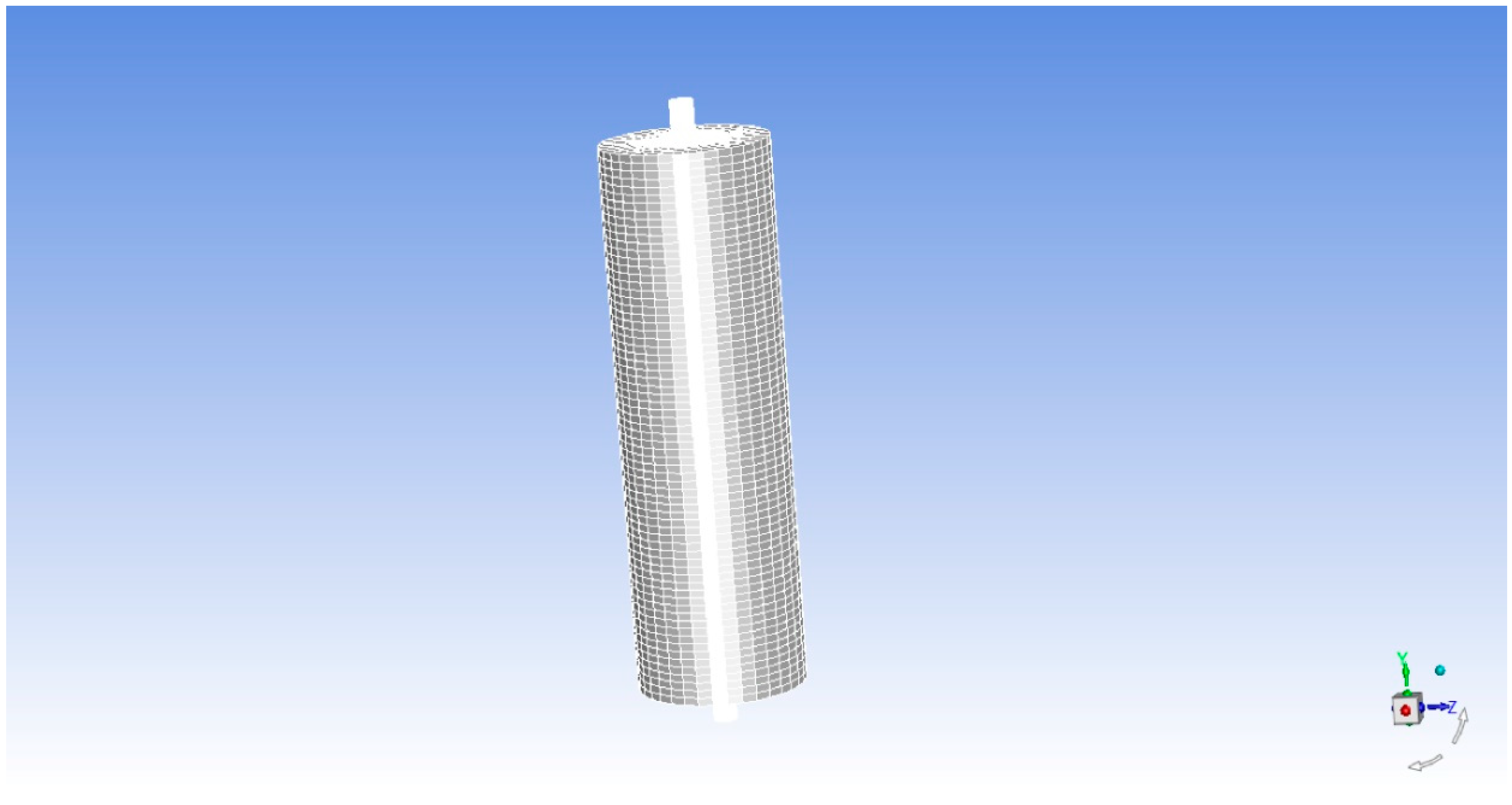
2.2.1. Computational Domain and Boundary Condition

According to the simplified model of humidifier mentioned above, the model of humidifier is meshed and its computational domain is determined. As shown in Table 1, the calculating mesh model of humidifier is a cylinder with 230 mm diameter and 700 mm height. The diameter of air inlet and outlet is 32 mm and the length is 50 mm. The grid model has 140,792 grids and the total number of nodes is 141,715. The grid can meet the requirements of calculation after checking. Figure 1 shows the grid model of the humidifier.
The main boundary conditions of humidifier are inlet, outlet and other boundary conditions. The inlet medium of humidifier is air, and the velocity inlet is adopted. The boundary parameters of the inlet are the basic parameters of the air, the inlet velocity of the air and the composition of the air, including the inlet velocity and air composition. The outlet is wet air and pressure outlet is used. Other interfaces use solid wall boundary conditions. In addition, a heat source is set at the bottom of the humidifier to simulate the water temperature change of the humidifier.

2.2.2. Computational Model and Method

The humidification process of humidifier involves heat and mass transfer between water and air. Therefore, multiphase flow model and component transportation are needed in calculation. In this paper, VOF (Volume of Fluid) model is used to deal with arbitrary free surface. Its principle is to determine the position and shape of free surface by calculating the function of fluid volume per unit mesh volume. In the calculation of VOF model, the volume fraction of gas phase and liquid phase are introduced respectively, so the governing equation of VOF model is determined. Continuity equation is as followed:
ρ m t + ( ρ m u i ) x i = 0 .
The momentum equation is:
( ρ m u j ) t + ( ρ m u i u j ) x i = p x j + ρ m g i + x i [ ( μ m + μ i ) ( u i x j + u j x i ) ] .
The energy equation is:
t k = 1 3 ( α k ρ k E k ) + t k = 1 3 [ α k u i ( ρ k E k + p ) ] = p x j ( k e f f T x j ) .
The volume rate equation is:
α g t + x i ( α g u i ) = 0 ,
α g + α l = 0 ,
ρ m = α l ρ l + α g ρ g ,
μ m = α l u l + α g u g ,
where,   u i is the velocity component, t is the time, T is the temperature, g is the gravitational acceleration, E k   is the energy of the k-phase fluid, ρ k   is the density of the k-phase fluid, k e f f   is the heat transfer coefficient, μ m   is the viscosity and p   is the pressure,   x i   is the coordinate direction.
The mass transfer process between gas and liquid phases can be expressed as follows:
p < p v , m ˙ = C e v a p V c h σ ρ l ρ v ( 2 3 p v p p l ) 1 2 ρ l α l ρ m ,
p > p v , m ˙ + = C c o n d V c h σ ρ l ρ v ( 2 3 p p v p l ) 1 2 ρ v α v ρ m ,
where, p v is the saturated vapor pressure of the liquid and the subscripts l and v denote liquid phase and vapor phase respectively.
In addition, DPM (Discrete Phase Model) is needed to simulate the spray nozzle model. DPM can simulate the discrete second phase in the flow field in Lagrangian coordinates. The second phase is usually spherical particles, such as droplets, bubbles, etc., which are generally distributed in the continuous phase. The governing equation of DPM model is:
m p c p d T d t = h A ( T T p ) + d m p d t q ,
where the left side of the equation is convective heat transfer and the right side is gasification heat transfer.   m p   is the mass of discrete phase,   c p is the specific heat capacity of discrete phase, h is the convective heat transfer coefficient, A is the surface area of discrete phase particles,   T is the gas phase temperature,   T p is the temperature of discrete phase droplets and q is the latent heat of vaporization. After determining the governing equation of the DPM model, it can be solved in software, and spray angle, humidifying water temperature, spray pressure, nozzle outlet velocity and mass flow rate of spray can be set. The temperature distribution of atomizing nozzle model is shown in Figure 2.The temperature of the outlet of the nozzle is set to 70 °C (340 K), the water flow rate is 1 m∙s−1, the pressure is 300 kPa, the diameter of the spray particles is 1 mm and the spray angle is 60 degrees.
In the calculation, the pressure-based solver was used, and the time type was unsteady. The equations were solved in turn. The standard model k ε   was chosen for the viscosity model, and the default SIMPLE algorithm was used for the pressure-velocity coupling algorithm. The truncation error was controlled within a relative tolerance of 10−6.

3. Results and discussion

There are many factors affecting the performance of the humidifier, such as air flow rate, humidifying water temperature. Therefore, these different factors are simulated to verify their impact on the performance of the humidifier, so as to provide a basis for improving the design of humidifier.

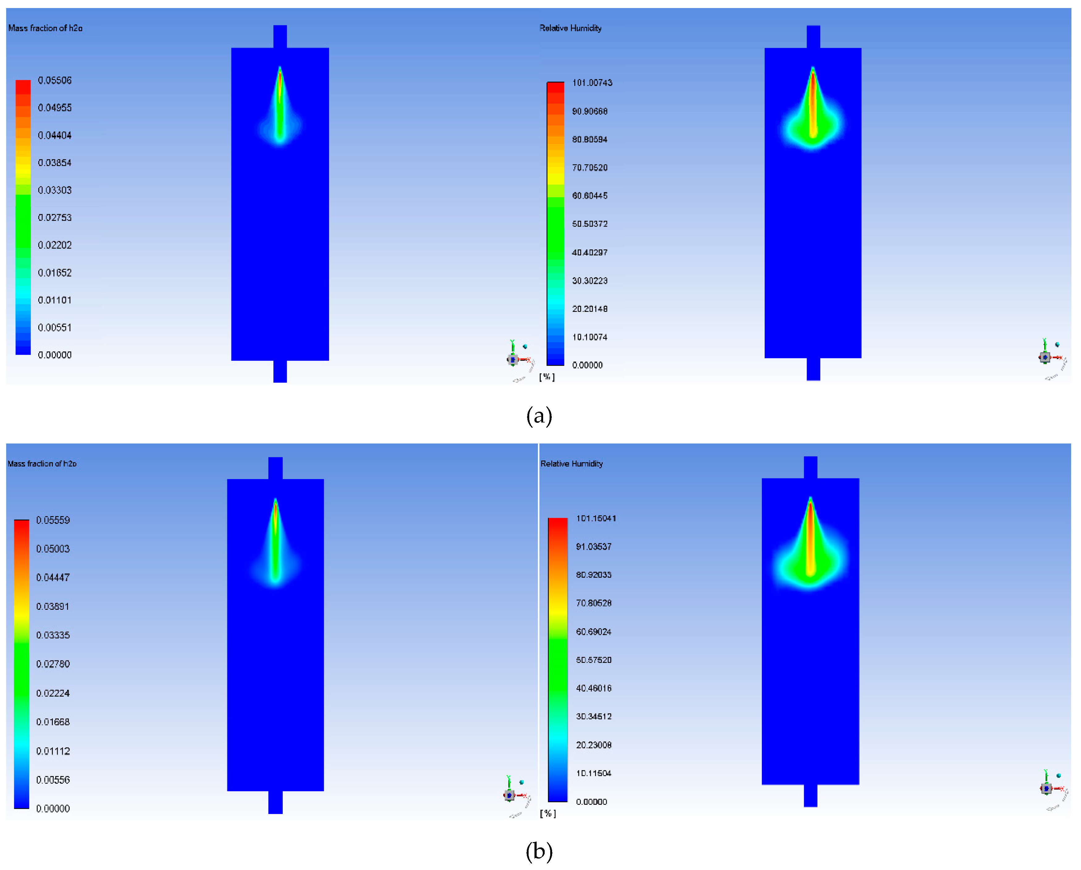
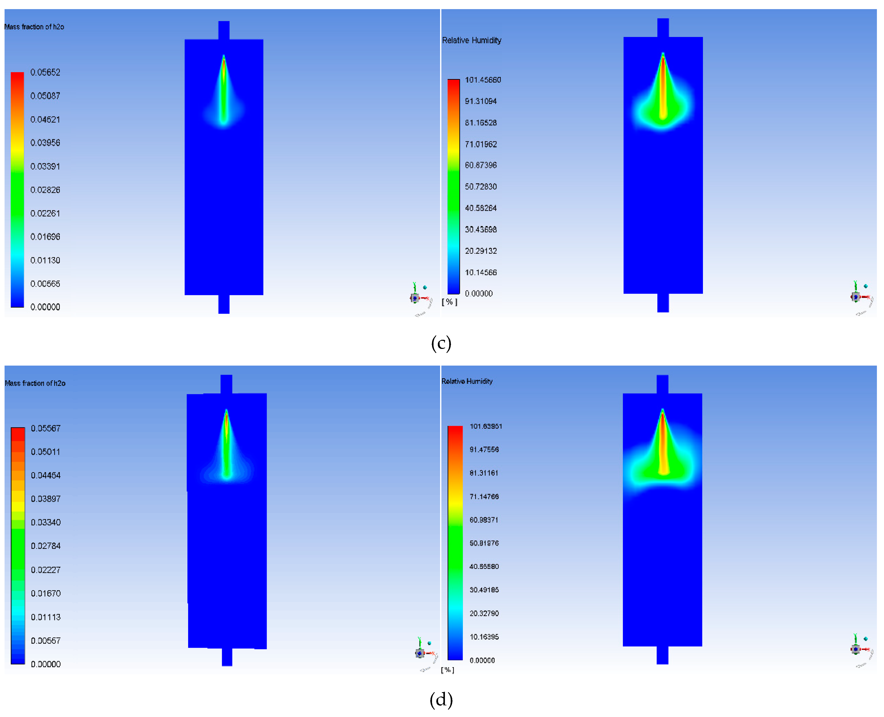
3.1. Effect of Air Flow Velocity on Humidification

In order to verify the effect of different air inlet velocities on humidification, the air inlet velocities are set to 5 m∙s−1, 10 m∙s−1, 15 m∙s−1 and 20 m∙s−1 to simulate the changes of air humidity at the outlet of the humidifier under the same other conditions, the humidifying water temperature is 70 °C.The parameters for the model are shown in Table 1. Figure 3 shows the mass fraction of water vapor and relative humidity at the outlet of the humidifier.
Figure 3 and Figure 4 show that the humidity at the outlet of the humidifier changes with the inlet gas velocity. The left figure of Figure 3a–d shows the water mass fraction at the outlet of the humidifier, and the right figure shows the relative humidity of the gas at the outlet of the humidifier. It can be seen that the humidity at the outlet of the humidifier decreases with the increase of the gas flow rate. When the inlet air flow velocity changes to 5 m∙s−1, 10 m∙s−1, 15 m∙s−1 respectively, the water vapor fraction of the outlet gas decreases almost linearly. When the air flow velocity increase to 15 m∙s−1, the water vapor fraction of the outlet gas decreased significantly. This is because the inlet air velocity is too high, which leads to the decrease of the mass transfer rate of water, and finally leads to the significant decrease of humidification performance of the humidifier. Since only one atomizing nozzle is added here to reduce the amount of calculation, the mass fraction of water vapor in the outlet air is very small. According to this comparative analysis, in order to ensure the humidity of the outlet gas, it is necessary to determine the air flow rate according to the power of the humidifying system, so as to calculate the required humidifying amount and obtain the appropriate humidifying water flow.

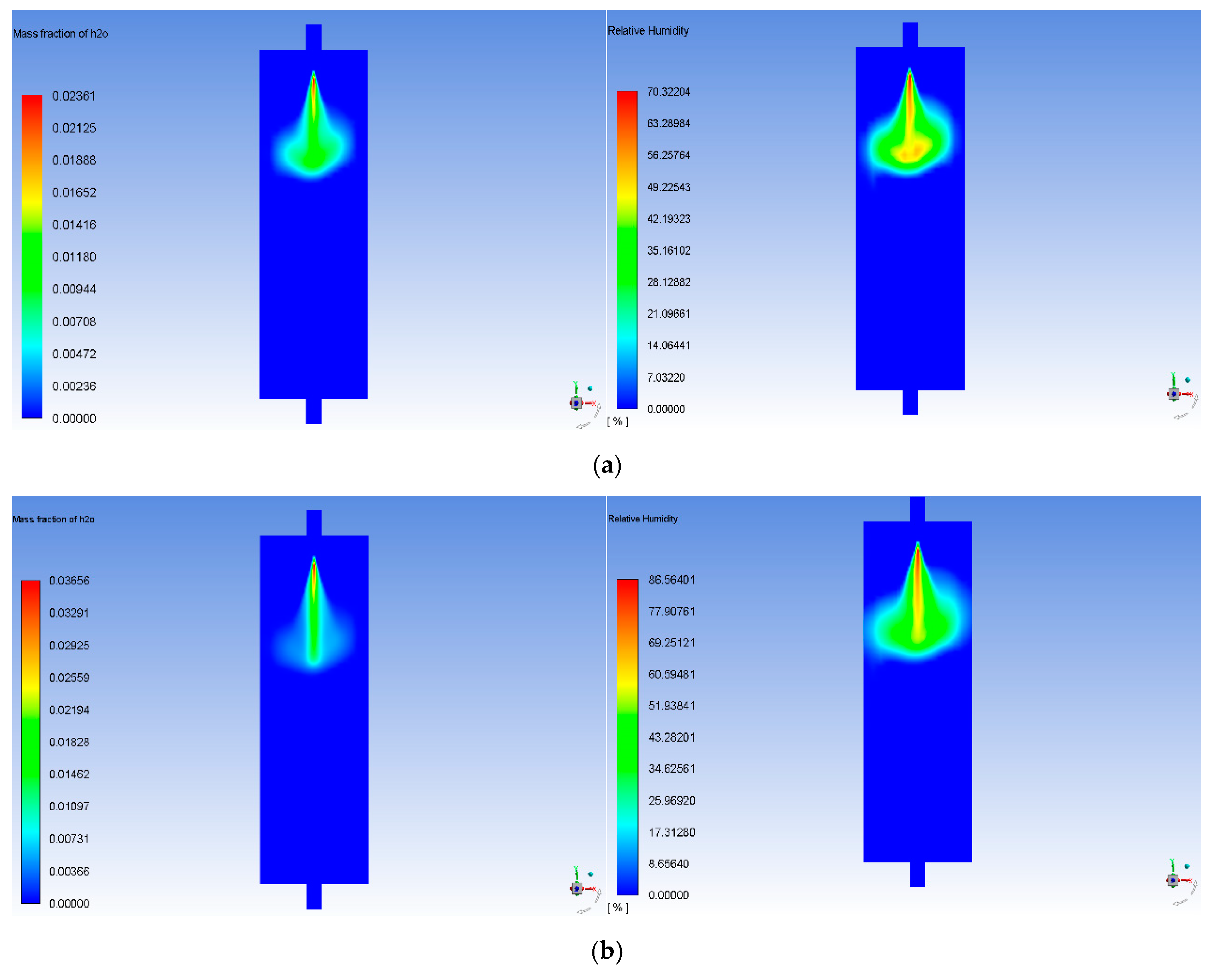
3.2. Effect of Humidifying Water Temperature on Humidification

After determining the influence of air velocity on humidifying effect of humidifier, the influence trend of humidifying water temperature on humidifying effect of humidifier is calculated. The humidification process of the humidifier was calculated by setting the temperature to 50 °C, 60 °C and 70 °C with the air flow rate of 5 m∙s−1. The results are shown in Figure 5. The left figure of Figure 5a–c shows the water mass fraction at the outlet of the humidifier, and the right figure shows the relative humidity of the gas at the outlet of the humidifier.
From Figure 5 and Figure 6, it can be seen that the humidifying water temperature changes from 50 to 70 °C, and the water vapor mass fractions of the outlet air of the humidifier are 2.36 × 10⁻⁴, 3.656 × 10⁻⁴ and 5.567 × 10⁻⁴, respectively. It can be concluded that with the increase of the humidifying water temperature, the humidifying effect of the humidifier is better and better, and the humidity content of the outlet gas is higher. Besides, it can be seen that the water vapor fraction at the outlet of the humidifier changes approximately linearly with the humidifying water temperature. By comparing Figure 4 and Figure 6, it can be found that the change of humidifying water temperature has a more obvious influence on the humidifying performance of the humidifier. With the humidifying water temperature rising 20 °C, the humidifying performance of the humidifier was doubled. This is because that, as the water temperature increases, the surface tension of the water decreases, which leads to the bubble in the water being easily broken and the mass transfer rate of the water being accelerated, which leads to the improvement of humidification performance of the humidifier.

3.3. Performance Verification of the Humidifier

After verifying the influence of the inlet air velocity and water temperature of the humidifier on the performance of humidifier, the humidification process of 10 kW humidification system is simulated. The air inlet flow rate is 1000 L∙min−1, the number of atomizing nozzles is 9, the mass flow rate of the humidifying water is 0.027 g∙s−1, and the humidifying water temperature is 70 °C. Figure 7a is the temperature distribution of nine atomizing nozzle models, Figure 7b shows the water mass fraction at the outlet of the humidifier and Figure 7c shows the relative humidity of the gas at the outlet of the humidifier.
From Figure 7, it can be seen that the humidifier outlet humidity of the 10 kW humidification system designed in this paper can reach more than 99%, which basically meets the requirement of obtaining basically saturated humid air and effectively avoids the problem of insufficient humidification capacity. It is worth noting that the relative humidity of the outlet gas has exceeded 100%. It may be that the gas has been fully humidified at this time, so a large number of liquid droplets are carried in the outlet gas, which results in the relative humidity exceeding 100%. Besides, there are a lot of droplets near the nozzle, the gas here carries a lot of liquid water because of the high gas velocity, so in order to avoid droplets being carried into the stack causing flooding, the top of the humidifier is designed to fill a large number of ball rings, thus filtering out the liquid droplets. It is made of metal sheet punching, and two rows of window holes with protruding tongue blades are cut out on the ring wall. Five tongue blades in each row of windows bend into the ring and point to the center of the ring, almost overlapping in the center, and the positions of the upper and lower layers of window holes are staggered with each other. The ball ring is usually made of plastic or metal and has the advantages of high flux, low pressure loss, high separation efficiency and high operating flexibility. So it is good at filtering out liquid water droplets in the gas at the humidifier outlet

4. Conclusions

Temperature and humidity have an important impact on the performance of fuel cell. As a test tool for fuel cell performance, the temperature and humidity control module of the test platform needs to be studied. In this paper, a humidifier combined with bubbling and spraying is adopted for the application of test platform, and the numerical simulation model of the humidifier is established. On the basis of the model, the influence of the humidification performance of the humidifier is verified by numerical simulation. The simulation results show that the inlet flow velocity and water temperature of the humidifier are important factors affecting the performance of the humidifier. It indicates that the humidifying performance of humidifier becomes worse with the increase of inlet air velocity. The water vapor mass fraction changes from 5.567 × 10⁻⁴ to 5.505 × 10⁻⁴, when the inlet air velocity changes from 5 to 20 m∙s−1. And with the increase of the humidifying water temperature, the performance of the humidifier is better and better, and the water vapor content of the outlet gas is higher. The water vapor mass fraction changes from 2.36 × 10⁻⁴ to 5.567 × 10⁻⁴, when the humidifying water temperature changes from 50 to 70 °C. Comparing the influence of inlet air velocity and humidifying water temperature on the humidifying performance of the humidifier, it can be found that the humidifying water temperature has a greater influence on the performance of the humidifier. It is because that, as the water temperature increases, the surface tension of the water decreases, which leads to the bubble in the water being easily broken and the mass transfer rate of the water being accelerated. In order to make the gas can be fully humidified, the humidifier uses 9 atomizing nozzles. The final results show that the humidifier designed can meet the humidification requirements of 10 kW test platform.

Author Contributions

Conceptualization, T.M., K.W.; data curation, K.W.; funding acquisition, T.M.; methodology, K.W.; project administration, T.M.; formal analysis, T.M. and K.W.; investigation, K.W.; resources, T.M.; software, K.W.; supervision, T.M.; validation, K.W.; visualization, K.W.; writing—original draft, T.M. and K.W.; writing—review and editing, Q.Z., M.C., W.L. and W.J.

Funding

This research was funded by the National key research and development program (Fuel Cell Engine Integration and Control for Heavy Truck) and the Research and Development Program in Key Areas of Guangdong Province (No. 2019B090909002).

Conflicts of Interest

The authors declare no conflict of interest. The funders had no role in the design of the study; in the collection, analyses, or interpretation of data; in the writing of the manuscript, or in the decision to publish the results.

Nomenclature

ρ density
t time
u , v , w the components of velocity vectors in the x , y , z direction
μ dynamic viscosity
S u , S v , S w source terms
c p   specific heat capacity
T temperature
k heat transfer coefficient
STviscous dissipation term
c s   volume concentration of component s
D s   diffusion coefficient of component s
S s productivity of component s
u i velocity component
g gravitational acceleration
E k energy of the k-phase fluid
p pressure
x i coordinate direction
p v saturated vapor pressure
m p mass of discrete phase
h convective heat transfer coefficient
q latent heat

References

  1. Migliardini, F.; Unich, A.; Corbo, P. Experimental comparison between external and internal humidification in proton exchange membrane fuel cells for road vehicles. Int. J. Hydrogen Energy 2015, 40, 5916–5927. [Google Scholar] [CrossRef]
  2. Cha, D.; Jeon, S.W.; Yang, W.; Kim, D.; Kim, Y. Comparative performance evaluation of self-humidifying PEMFCs with short-side-chain and long-side-chain membranes under various operating conditions. Energy 2018, 150, 320–328. [Google Scholar] [CrossRef]
  3. Bernardi, D.M.; Verbrugge, M.W. A mathematical model of the solid polymer-electrolyte fuel cell. J. Electrochem. Soc. 1992, 139, 2477–2491. [Google Scholar] [CrossRef]
  4. Buechi, F.N.; Srinivasan, S. Operating proton exchange membrane fuel cells without external humidification of the reactant gases. J. Electrochem. Soc. 1997, 144, 2767–2772. [Google Scholar] [CrossRef]
  5. Choi, K.H.; Park, D.J.; Rho, Y.W.; Kho, Y.T.; Lee, T.H. A study of the internal humidification of an integrated PEMFC stack. J. Power Sources 1998, 74, 146–150. [Google Scholar] [CrossRef]
  6. Staschewski, D. Internal humidifying of PEM fuel cells. Int. J. Hydrogen Energy 1996, 21, 381–385. [Google Scholar] [CrossRef]
  7. Vasu, G.; Tangirala, A.K.; Viswanathan, B.; Dhathathreyan, K.S. Continuous bubble humidification and control of relative humidity of H for a PEMFC system. Int. J. Hydrogen Energy 2008, 33, 4640–4648. [Google Scholar] [CrossRef]
  8. Nikiforow, K.; Ihonen, J.; Keranen, T.; Karimaki, H.; Alopaeus, V. Modeling and experimental validation of H2 gas bubble humidifier for a 50 kW stationary PEMFC system. Int. J. Hydrogen Energy 2014, 39, 9768–9781. [Google Scholar] [CrossRef]
  9. Kuhn, R.; Manke, I.; Hartnig, C.; Krüger, P.; Kleinau, S.; Dawson, M.; Geyer, J.; Roscher, M. Dynamic fuel cell gas humidification system. Int. J. Hydrogen Energy 2012, 37, 7702–7709. [Google Scholar] [CrossRef]
  10. Hyun, D.; Kim, J. Study of external humidification method in proton exchange membrane fuel cell. J. Power Sources 2004, 126, 98–103. [Google Scholar] [CrossRef]
  11. Casalegno, A.; Antonellis, S.D.; Colombo, L.; Rinaldi, F. Design of an innovative enthalpy wheel based humidification system for polymer electrolyte fuel cell. Int. J. Hydrogen Energy 2011, 36, 5000–5009. [Google Scholar] [CrossRef]
  12. Jung, S.H.; Kim, S.L.; Min, S.K.; Park, Y.; Lim, T.W. Experimental study of gas humidification with injectors for automotive PEM fuel cell systems. J. Power Sources 2007, 170, 324–333. [Google Scholar] [CrossRef]
  13. Sung, C.C.; Bai, C.Y.; Chang, S.J.; Chen, J.H. Controllable fuel cell humidification by ultrasonic atomization. J. Power Sources 2013, 239, 151–156. [Google Scholar] [CrossRef]
  14. Yan, W.M.; Chen, C.Y.; Jhang, Y.K.; Chang, Y.H.; Amani, P.; Amani, M. Performance evaluation of a multi-stage plate-type membrane humidifier for proton exchange membrane fuel cell. Energy Convers. Manage. 2018, 176, 123–130. [Google Scholar] [CrossRef]
  15. Chen, C.Y.; Chang, Y.H.; Li, C.H.; Chang, C.C.; Yan, W.M. Physical properties measurement and performance comparison of membranes for planar membrane humidifiers. Int. J. Heat Mass Transfer 2019, 136, 393–403. [Google Scholar] [CrossRef]
  16. Chang, Y.; Qin, Y.; Yin, Y.; Zhang, J.; Li, X. Humidification strategy for polymer electrolyte membrane fuel cells—A review. Appl. Energy 2018, 230, 643–662. [Google Scholar] [CrossRef]
  17. Hwang, J.J.; Hwang, H.S. Parametric studies of a double-cell stack of PEMFC using Grafoil™ flow-field plates. J. Power Sources 2002, 104, 24–32. [Google Scholar] [CrossRef]
  18. Hsieh, S.S.; Yang, S.H.; Kuo, J.K.; Huang, C.F.; Tsai, H.H. Study of operational parameters on the performance of micro PEMFCs with different flow fields. Energy Convers. Manage. 2006, 47, 1868–1878. [Google Scholar] [CrossRef]
  19. Williams, M.V.; Kunz, H.R.; Fenton, J.M. Operation of Nafion®-based PEM fuel cells with no external humidification: Influence of operating conditions and gas diffusion layers. J. Power Sources 2004, 135, 122–134. [Google Scholar] [CrossRef]
  20. Santarelli, M.G.; Torchio, M.F. Experimental analysis of the effects of the operating variables on the performance of a single PEMFC. Energy Convers. Manage. 2007, 48, 40–51. [Google Scholar] [CrossRef]
Figure 1. Computational domain grid of humidifier.
Energies 12 03839 g001
Figure 2. Temperature distribution model of atomizing nozzle.
Energies 12 03839 g002
Figure 3. Water vapor mass fraction and relative humidity at the outlet of humidifier at different inlet gas velocity: (a) The inlet air velocity is 5 m∙s−1; (b) the inlet air velocity is 10 m∙s−1, (c) the inlet air velocity is 15 m∙s−1, (d) the inlet air velocity is 20 m∙s−1.
Energies 12 03839 g003aEnergies 12 03839 g003b
Figure 4. The relationship between water vapor mass fraction at the outlet of humidifier and air velocity.
Energies 12 03839 g004
Figure 5. Water vapor mass fraction and relative humidity at the outlet of humidifier at different temperatures: (a) The temperature is 50 °C; (b) the temperature is 60 °C; (c) the temperature is 70 °C.
Energies 12 03839 g005aEnergies 12 03839 g005b
Figure 6. The relationship between water vapor mass fraction at the outlet of humidifier and humidifying water temperature.
Energies 12 03839 g006
Figure 7. Verification of humidification performance of the 10 kW humidifier: (a) The temperature distribution of nine atomizing nozzle models; (b) water vapor mass fraction at the outlet of the humidifier; (c) relative humidity at the outlet of the humidifier.
Energies 12 03839 g007
Table 1. Parameters for the model.
ParametersValue
diameter230 mm
height700 mm
diameter of inlet and outlet32 mm
length of inlet and outlet50 mm
inlet air velocity5 m∙s−1, 10 m∙s−1, 15 m∙s−1,20 m∙s−1
humidifying water temperature50 °C, 60 °C, 70 °C
water pressure300 kPa
water flow rate 1 m∙s−1
diameter of the spray particles1 mm
spray angle60 degrees

