Abstract
Three-dimensional moderator flow in the calandria tank of CANDU-6 pressurized heavy water reactor (PHWR) is computed with Open Field Operation and Manipulation (OpenFOAM), an open-source computational fluid dynamics (CFD) code. In this study, numerical analysis is performed on the real geometry model including 380 fuel rods in the calandria tank with the heat-source distribution to remove uncertainty of the previous analysis models simplified by the porous media approach. Realizable k-ε turbulence model is applied, and the buoyancy due to temperature variation is considered by Boussinesq approximation for the incompressible single-phase Navier-Stokes equations. The calculation results show that the flow is highly unsteady in the moderator. The computational flow visualization shows a circulation of flow driven by buoyancy and asymmetric oscillation at the pseudo-steady state. There is no region where the local temperature rises continuously due to slow circulating flow and its convection heat transfer.
1. Introduction
CANadian Deuterium Uranium (CANDU) reactors have been introduced in Korea since the late 1980s, and four units of CANDU-6 reactors were constructed in the Wolsong areas [1]. The horizontal fuel channels in a CANDU-6 reactor (a pressurized heavy water reactor, PHWR) are submerged in the heavy water (D2O) pool which is contained by a cylindrical tank called calandria. One of the important design features of the CANDU-6 reactor is the use of moderator as a heat sink during some postulated accidents such as a large-break Loss of Coolant Accident (LOCA). Therefore, it is one of the major concerns in the CANDU safety analyses to estimate the local subcooling margin of the moderator inside the calandria tank.
Previous experimental studies [2] showed that the film boiling on the outside surface of fuel channels would be unlikely to occur if the local moderator subcooling is sufficient. Therefore, an accurate prediction of the moderator temperature distribution in the calandria tank is needed to confirm the channel integrity [3]. To predict the local temperature of the calandria tank, numerous experimental and numerical studies have been performed so far. Huget et al. [4,5] conducted two-dimensional moderator circulation tests at the STERN Laboratories Inc. (STERN Lab.), and they validated a specific code, MODerator TURbulent Circulation (MODTURC) [4] and its advanced version, Co-Located Advance Solution (MODTURC_CLAS) [5] against the experimental results [6] of the velocity and the temperature distributions.
Temperature distribution in the moderator is highly affected by flow patterns and circulation characteristics which themselves are generated as a result of interactions between the inertia forces (produced by inlet jets) and buoyancy forces (resulting from heat addition) in the calandria (see Figure 1). Given the differences in the moderator heat load, flow rate and inlet nozzle distribution and design, each CANDU reactor has a different flow pattern and temperature distribution during normal operation. Therefore, Korea Atomic Energy Research Institute (KAERI) installed a 1/4 scaled Moderator Circulation Test (MCT) facility [7] that is representative of CANDU-6 reactors with 380 fuel channels. These test results [8] showed that the moderator circulation flow has a mixed flow patterns with combination of inertial forces and buoyancy forces under the CANDU-6 operation conditions. Furthermore, the flow oscillation and unsteady flow behavior were observed, which were not reported in the previous studies [4,6].
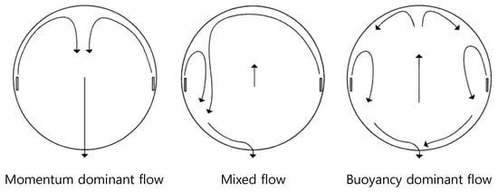
Figure 1.
Flow pattern inside a calandria by balance of buoyancy and momentum forces.
There have been numerous computational efforts to estimate the thermal hydraulics in the calandria tank using CFD codes. Hadaller et al. [9] obtained a tube bank pressure drop model for tube bundle region of the calandria tank and implemented it into the MODTURC_CLAS code. Yoon et al. [10] used a commercial code, CFX to develop a CFD model with a porous media approach for the core region. However, it is known that porous media modeling provides only average values of flow velocities and temperatures in the moderator and do not give any information about 3-D local flow variables near tube solid walls, which are necessary to implement accurate heat transfer calculations. Recently, porous media modeling in the tube bank region of core using economic computing resources are replaced by the full geometric model of calandria tubes requiring high computing resources. Sarchami et al. [11] used another FLUENT code to model all the calandria tubes as they are without any approximation for the core region. They could show the nature of moderator temperature fluctuations by dynamic flow behavior with completion between the upward moving buoyancy driven flows and the downward moving momentum driven flows. Teyssedou et al. [12] conducted FLUENT code simulation of moderator flow around calandria tubes of CANDU-6 and showed that the standard k-e model is appropriate for turbulence model to perform this kind of simulation. Application of FLUENT and CFX code is successfully performed for the reduced-scale CFD models for various thermal hydraulics problems in nuclear engineering also by the authors [13,14].
In this study, Open Field Operation and Manipulation (OpenFOAM) [15], an open-source CFD solver, is used to simulate the three-dimensional flows improving the computational efficiency by parallel computing which does need no proprietary license. The feasibility on the computation of 3-D flow has been tested and validated by the comparison with other codes by the authors [16], but the models are just focused on the pressure drop in a straight channel. In this paper, the full capacity of OpenFOAM CFD is tested for a turbulent unsteady flow as observed in the 1/4 scale of test [8] to resolve the 3-D structure of circulation flow in the moderator system of a real-scale CANDU-6 reactor.
We have studied the suitable grid levels and the validation of pressure drops with the comparison with various commercial codes such as ANSYS-CFX and COMSOL (COMputer SOLution) Multiphysics as well as experimental data using OpenFOAM [16]. However, the full simulation of CANDU-6 is not yet attempted because of its high complexity in three dimensions. From the dimensional analysis, the complex scale effects between prototype CANDU-6 and model MCT should be considered [7]. Therefore, the full-scale simulation is expected to show the overall flow physics with proper predictions of subcooling margin in this research. In the system codes, the difference of temperature or pressure between inlet and outlet is given as a lumped input parameter. For example, a system analysis code for PHWR, CATHENA [17] can consider a pipe network for tube bundles of fuel channels, but a three-dimensional numerical model is made for the present study to understand sophisticated flow physics such as turbulence diffusion and mixing, convective heat transfer, buoyancy forces, etc. in a moderator pool.
2. Simulation Method
2.1. Open Source Code
OpenFOAM has been developed by Henry Weller and Hrvoje Jasak in Imperial College. The source code has been opened to the public since 2004. This code is operated on the Linux-based O/S such as Ubuntu, so the copyright is absolutely free for every CFD program developer. This code is originated from the object-oriented programming (OOP) concept based on C++ program language. Solvers and libraries are defined as C++ classes. With the post processor ParaView, the graphical visualization becomes possible with a command paraFoam [15]. In this study, OpenFOAM version 2.3.1 (The OpenCFD Ltd., London, UK) is used. The numerical calculations are conducted with two OpenFOAM standard solver, “buoyantBoussinesqSimpleFoam” and “buoyantBoussinesqPimpleFoam”.
The governing equations of the solvers are incompressible continuity equation, the Navier-Stokes equations and energy equation for the heat transfer where the buoyant force is related in the source term in the momentum equation with Boussinesq approximation. The realizable k-ε turbulence model is also applied for the low Reynolds number turbulent flow in the moderator. Computation is performed with two stages to save the settling time for the pseudo-steady state: “buoyantBoussinesqSimpleFoam” is for steady flow using Semi-Implicit Method for Pressure-Linked Equations (SIMPLE) algorithm, while “buoyantBoussinesqPimpleFoam” is for unsteady flow using PISO, Pressure Implicit with Splitting of Operator, and SIMPLE (PIMPLE) algorithm because the latter one is known to be better for the time-accurate computation [15].
2.2. Governing Equations and Discretization
The hydraulic governing equations based on the single-phase incompressible flow are written in the vector form:
where , ρ, p are velocity vector, density, and pressure while the constants μ and fV are dynamic viscosity and body force per unit volume. Equation (1) is the continuity equation for incompressible flow, and the Navier-Stokes momentum equation, Equation (2) is decoupled from energy equation in the source term, or buoyancy force of Boussinesq approximation, , where β is the thermal expansion in the unit of 1/K, and T − T0 is the difference of temperature from the reference condition.
A realizable k-ε model, which is better for rotational flow, is used for the simulation of turbulent flow. This model includes two additional equations in a tensor form:
where is the modulus of mean rate-of-strain tensor, and . In Equations (3) and (4), the turbulent eddy viscosity is defined as:
where Equation (5) is substitute to Equation (2) for the consideration of turbulence. is not a constant like that of standard k-ε model but a function of , (angular velocity in the reference frame), (dissipation tensor), and (mean rate-of-rotation tensor), and in Equation (4) is specified as
Other coefficients in Equations (3) and (4) are listed as . The energy equation to get the temperature field for the computation of fV in Equation (2) is
where T is temperature; Cp is heat capacity; λ is thermal conductivity; Prt is turbulent Prandtl number, assumed as a constant of 0.85 for all the range of fluid, and QS is volumetric heat source, which should be specified in next section, Equation (8).
The convection terms of the governing equations are discretized with second order upwind scheme and diffusion terms are calculated with second order centered difference scheme. Turbulence equations and heat transfer equation were discretized with first order upwind scheme.
In the computation using OpenFOAM, SIMPLE algorithm, a kind of finite volume method (FVM) is applied for the iteration until the steady state for Equations (1) and (2). In this method, the pressure gradient term in Equation (2) is isolated, and sub-iterations should be performed between predictor and corrector [14]. The PIMPLE method is used for unsteady time marching, which is specified as no under-relaxation and multiple corrector steps in the calculation of momentum. PIMPLE is far accurate in time and applied to the unsteady computation instead of SIMPLE.
2.3. Boundary and Initial Conditions
The essential boundary conditions in this problem are listed as follows:
- Velocities: no-slip conditions at walls, and the mass flow rate is specified on the inlet, fixed to 127.4 kg/s per each inlet nozzle, or 1019 kg/s in total for the present problem. The inlet turbulent intensity is fixed as 5%, which can make the additional uncertainty for the turbulent flow linked with the full system;
- Pressure: zero pressure gradient conditions at walls and inlet, which should be valid under the assumption that the thickness of boundary layer is very thin. The outlet pressure is fixed by the moderator system;
- Temperature: the inlet temperature is fixed to 47.3 °C.
Total thermal power exerted to the whole system is 100 MW, which should be processed as the source term, QS in Equation (7) where the factor 1.089 (of course, the volume blockage of tubes is considered). The equivalent temperature, or the energy dived by density and heat capacity, should be considered in the energy equation of OpenFOAM where the temperature should be specified instead of power. The power distribution is defined as , and the shape functions are, in the dimensionless form [18,19],
where Equation (8) is obtained from group distributions of fuel bundles measured from the plant data in a Wolsong PHWR [10], and the correlation is regressed with a fourth-order least-square curve.
The initial temperature of the whole computational domain is 47.3 °C, and the flow is assumed stationary in the beginning of computation. Actually, the CANDU-6 moderator is liked with the system network, but we did an independent simulation for the moderator only. The properties of the fluid (D2O) for simulations are summarized in Table 1.

Table 1.
Material properties of the heavy water.
2.4. Grid Generation
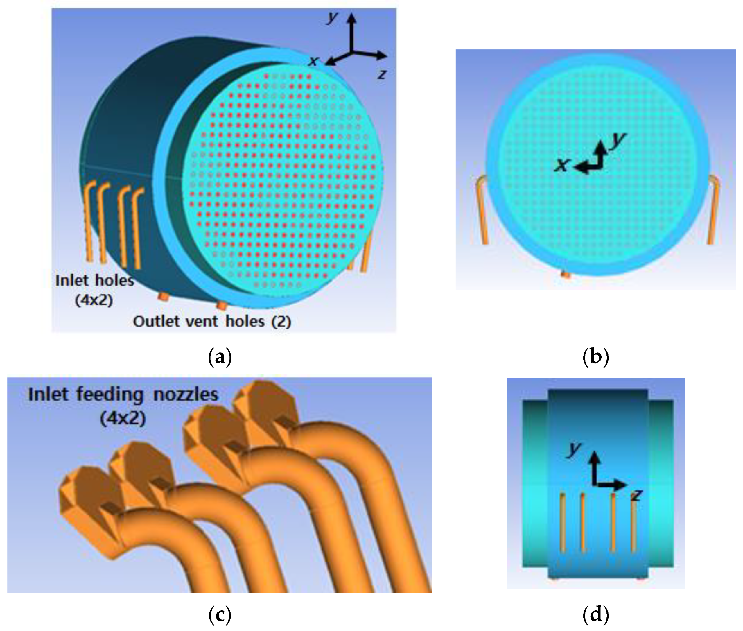
The prototype of CANDU-6 is such as Figure 2. The 380 circular rods called calandria tubes are allocated symmetry from the central line of tank; the inlet holes are four along each side part, i.e., eight in total with feeding nozzles consisting of four radial diffusers; and there are two outlet exits at the bottom. This prototype has an asymmetric shape for the cross section along the longitudinal direction because the outlet vent hole is tilted from the vertical midline.

Figure 2.
3-D modeling of the prototype: (a) 3-D shape; (b) axial view; (c) feeding nozzles; (d) side view.
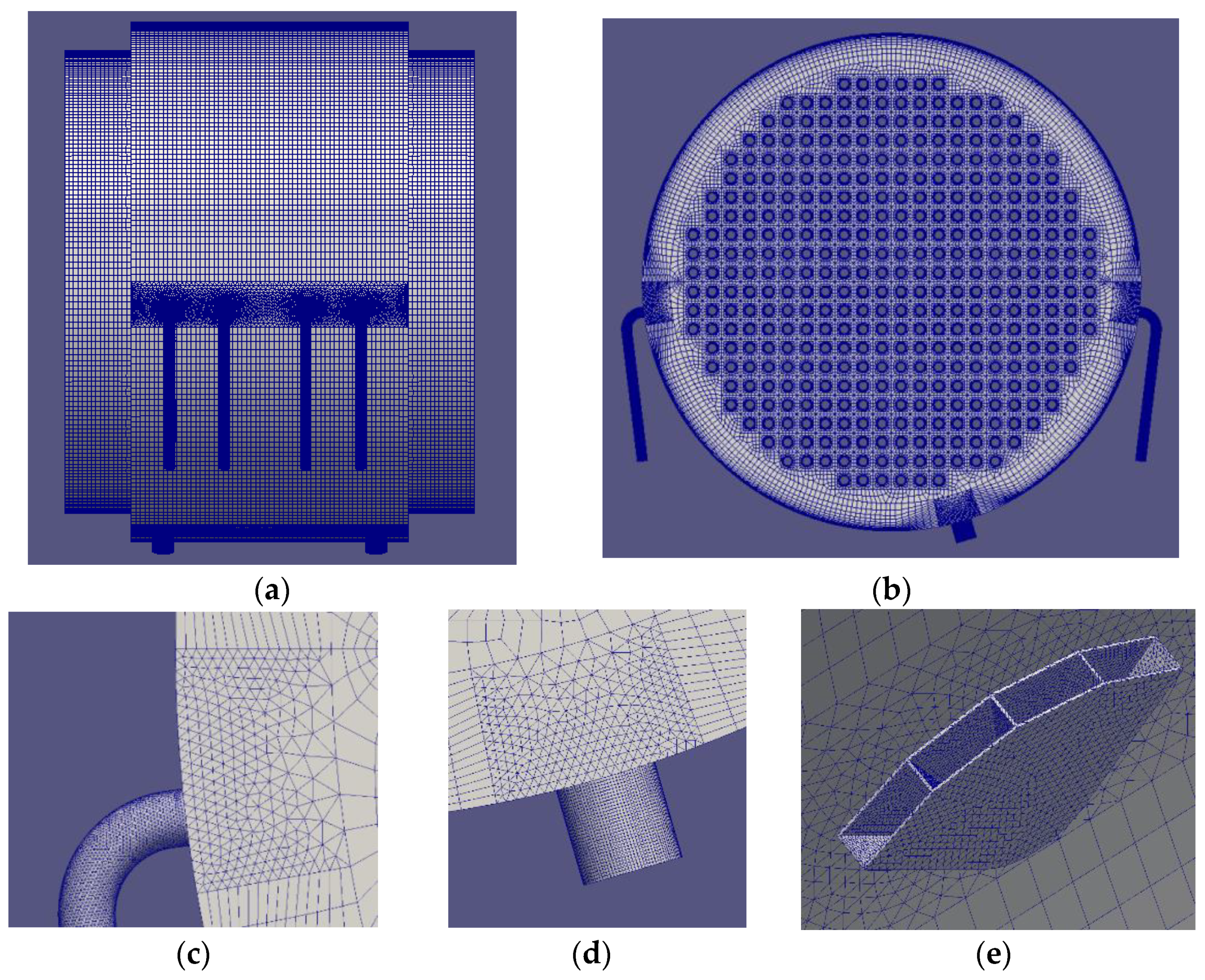
Figure 3 shows the three-dimensional unstructured grids at the view of lateral and longitudinal direction. The total grids are 6,740,446 consisting of 5,112,270 for the hexahedral, 13,112 for pyramids, and 1,615,064 for the tetrahedral. They are concentrated at the wall boundary with 15 stretched layers to increase the accuracy in turbulent boundary layers. The computation is done with a message passing interface (MPI) parallel machine where 24 processors are used. Each computational result is stored at multiple folders to assemble them in the post processor.
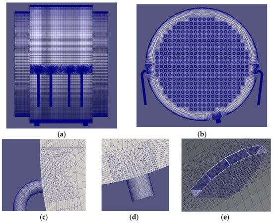
Figure 3.
Grids of the prototype: (a) side longitudinal; (b) planform sectional; (c) inlet plumbing; (d) outlet exit; and (d) feeding nozzle.
3. Result and Discussion
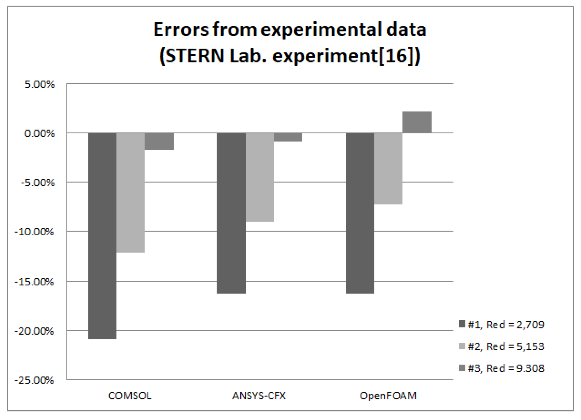
The numerical method is verified and validated in the previous research by the authors [14,16]. The pressure drop with comparison of STERN laboratory experiment shows an error within 16.3% from the experimental data [16] (see Figure 4). The pressure drop is measured for isolated four-row bank of aligned cylinders of 33.02 mm diameter and 71.4 mm spacing. The pressure sensors are in the distance of sixteen blocks of cylinders along the central axis. Three sets of experiments are used for this comparison, specified with the Reynolds number based on the tube diameter, Red = ρVd/μ. Among various codes such as ANSYS-CFX and COMSOL, the open source code OpenFOAM displayed similar or better level of coincidence for all kinds of turbulence models, and k-ε model was the best result. The modeling of two-dimensional heat flow can predict the temperature with a maximum local error of 3.5 °C, which can be a reduced model of CANDU-6 moderator [14].
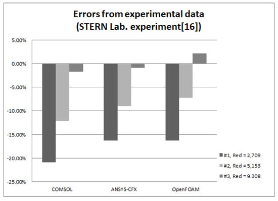
Figure 4.
Comparison of numerical results from various codes for the experiment of STERN laboratory.
3.1. Quasi-Steady State
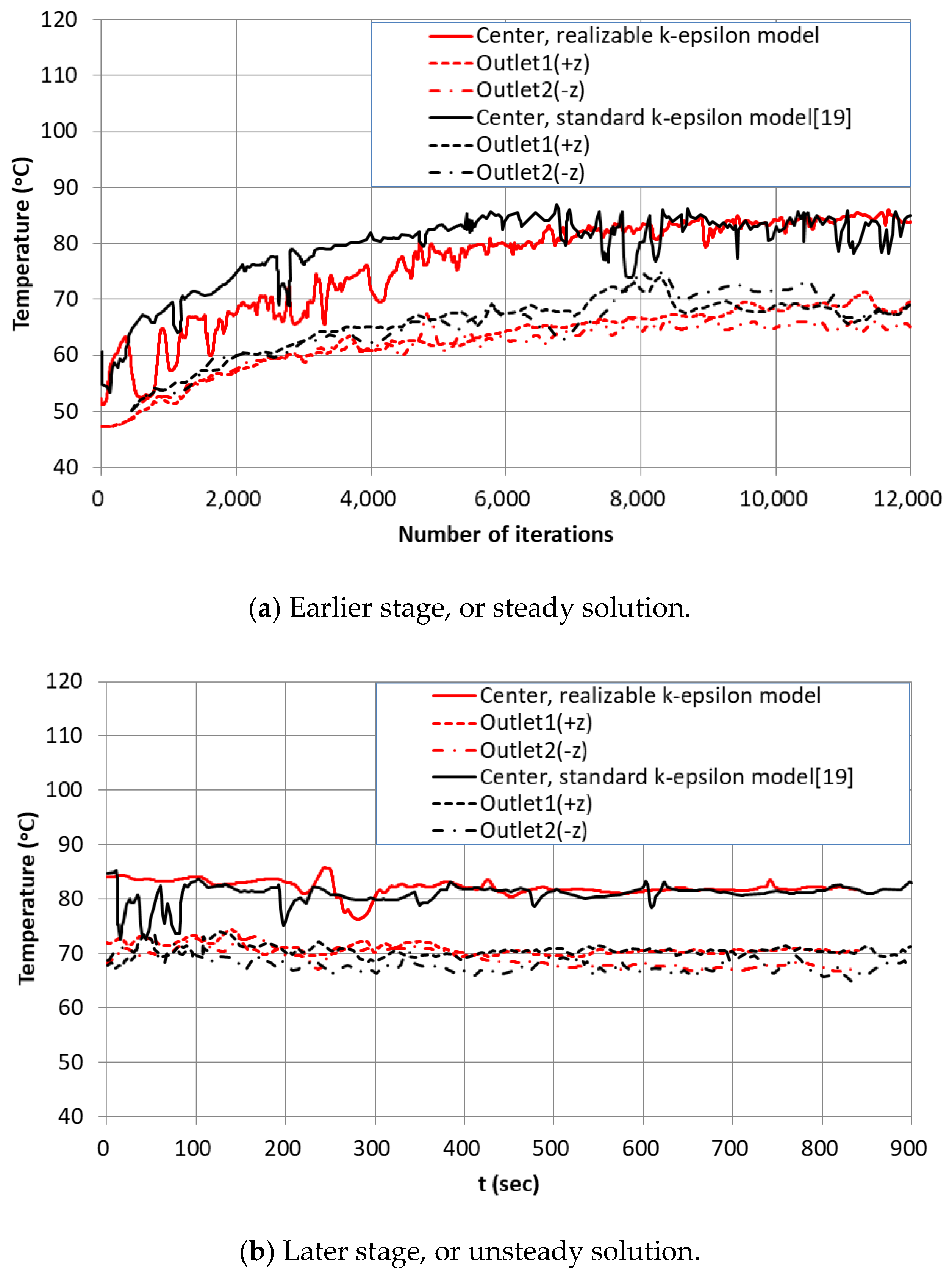
The solution is not converged to a steady state with segregated solvers such as SIMPLE or PIMPLE, but instead it fluctuates with oscillation [2]. In the earlier stage, steady solution is obtained with SIMPLE algorithm. After the computation is stabilized, in the later stage, the solution is time-marched to get the unsteady one. Figure 5 is the temperature at two outlets and the origin of (a) quasi-steady, or the center of calandria, before 12,000 time steps and (b) unsteady procedure to 850 s of physical time. The temperature of two outlets are slightly different from each other because of the asymmetry from flow instability. At the center, the time-averaged temperature is about 85 °C.
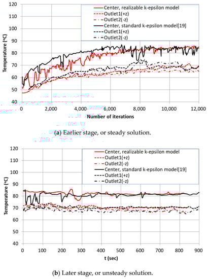
Figure 5.
Temperature at the center and two outlets.
3.2. Turbulent Model and Scale
In Figure 5, the present computational results are compared with those from the standard k-ε model [19]. With the realizable k-ε turbulent model, the convergence is slower than that with standard one in Figure 5a but shows overall better stable temperature in the pseudo-steady stage in Figure 5b. The inlet turbulence intensity is fixed to 5% [16].
To show how the grid system in Figure 4 can capture turbulent physics in a proper scale, the normalized wall distance, is plotted in Figure 6, which is ranged widely. At the outer wall, the maximum y+ exceeds 100 where the fast waterjet sweeps injected from the nozzles. The is distributed from 10 to 60 at the cylinder walls. However, with the use of the wall function, the value of should be enough in the most of computational domain of the present problem since the value less than 30 can often make the turbulent wake flow unstable even though that at the tube wall boundary must be maintained near unity [18].
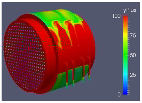
Figure 6.
Distribution of at 840 s.
3.3. Velocity and Temperature Fields in the Unsteady Solution
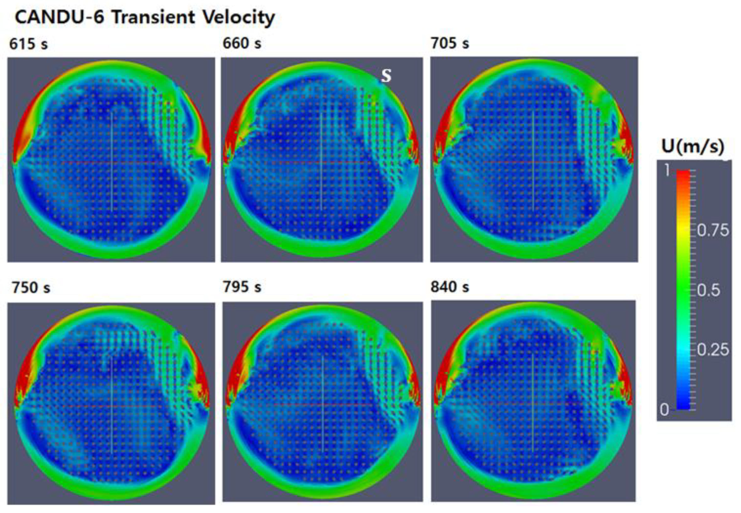
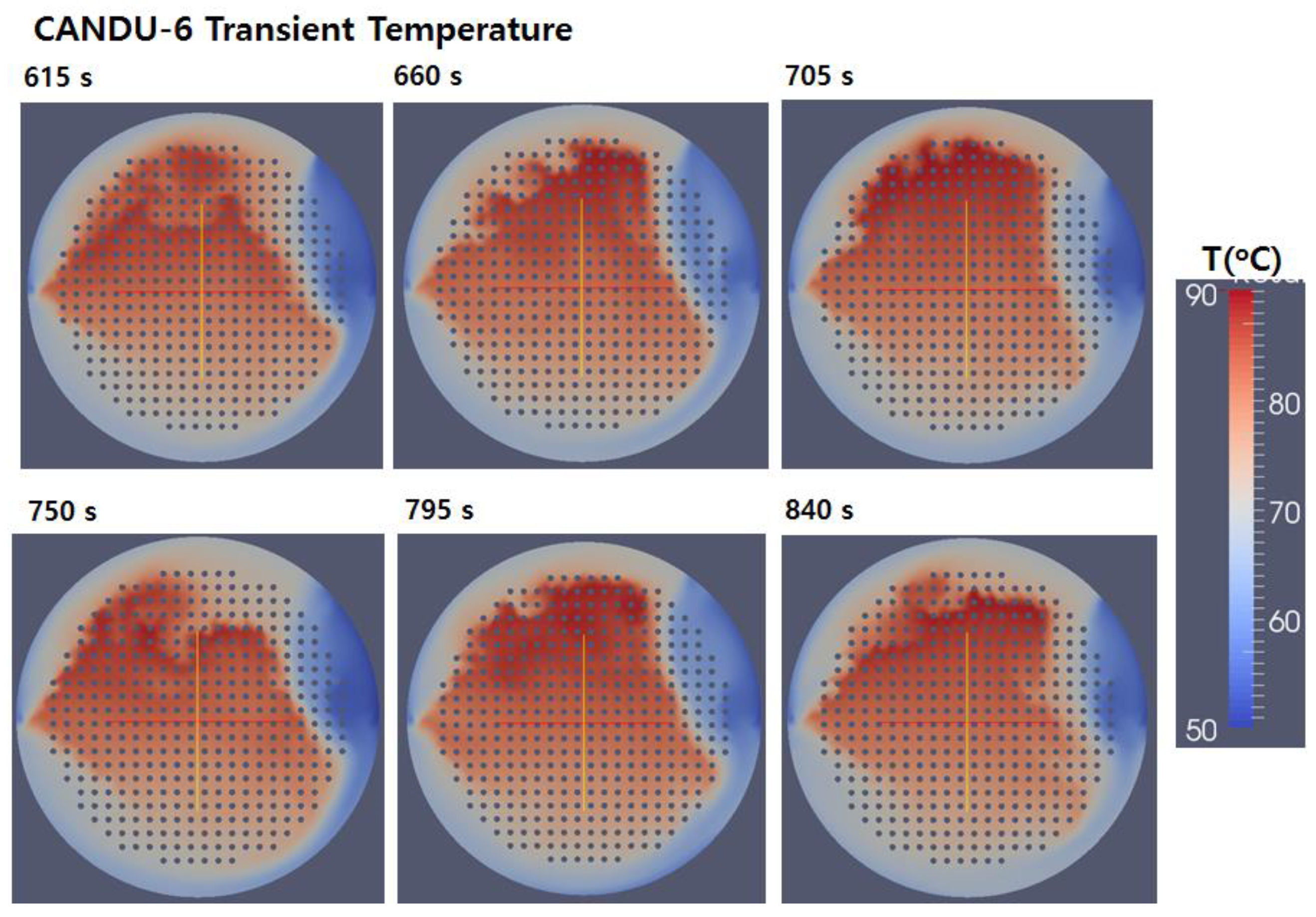
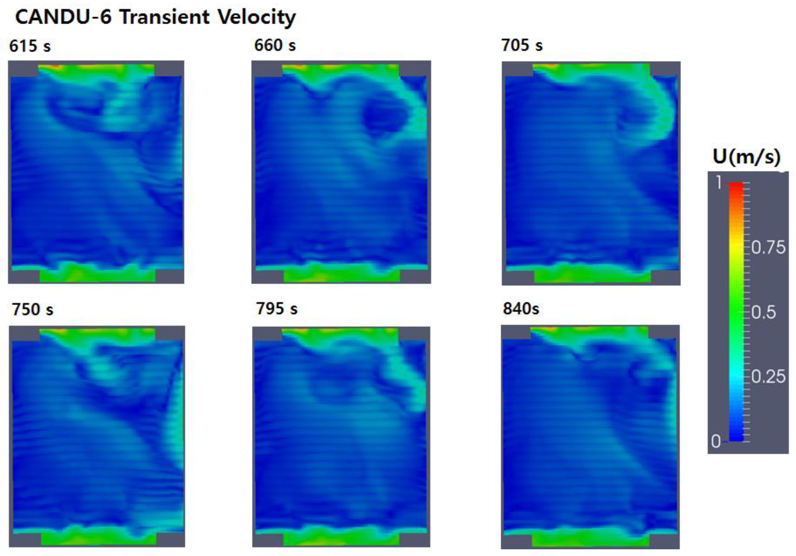
After the quasi-steady state after 12,000 iterations, the time is reset to zero, and the fields of velocity and temperature are visualized in Figure 7, Figure 8, Figure 9 and Figure 10 from 615 to 840 s.

Figure 7.
Velocity distribution at z = 0; 615–840 s.

Figure 8.
Temperature distribution at z = 0; 615–840 s.
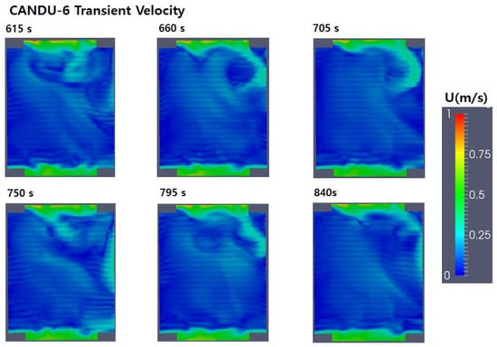
Figure 9.
Velocity distribution at x = 0; 615–840 s.
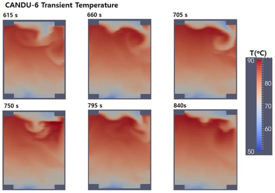
Figure 10.
Temperature distribution at x = 0; 615–840 s.
Figure 7 and Figure 8 are plotted at the sectional plane z = 0 (x-y plane), and the change of velocity and temperature are observed in the series of figures, respectively. In Figure 7, the cooling water from nozzles, initially to the upper direction or the positive y-axis, in both sides meets at a stagnation point, denoted with S in the upper right-hand side, the same tilt direction of vent hole. Please note that it is not symmetric. The flow field seems to be periodic for 225 s time difference. However, the temperature field in Figure 8 presents much more turbulent diffusion, so it becomes very difficult to find the obvious regularity. The period is not resolved from the figures, but the similar flow patterns are repeated with time passing: the cooling waterjet falls from the stagnation point, soaked into gaps of cylinders until the outflow at the vent hole. The heated water maintains balance of temperature at the upper region of tube bundles because of the buoyancy in the momentum transfer. The flow velocity is very slow less than 1 m/s in most of the domain, and no local region is found for the rapid increase of temperature thanks to the mixing of diffusive turbulent flow.
Figure 9 and Figure 10 are plotted at the sectional plane x = 0 (longitudinal), and the flow is not simple, too. In Figure 9, the flow velocity is so slow, but the marks of calandria tubes are dimly visible like stripes as they decelerate the circulation flow from the no-slip boundary condition. The maximum temperature stays about 89 °C in Figure 10, and cannot be found the region of successive increase of temperature.
The velocity distribution in Figure 7 and Figure 9 show obviously that the flow circulation penetrates the interval of circular rods decelerating the flow with a pressure drop. The diffused flow makes the temperature increase at the upper central region in Figure 8 because flow resistance takes the worse cooling efficient. In the temperature field view of Figure 8, the largest turbulent eddies can be discerned at the interface of different temperature at the upper half plane such as the mushroom shape. They merge and separate continuously, developing a highly complex turbulent structure, so the high temperature difference of about 20 °C is dramatically visualized in both Figure 8 and Figure 10.
In Figure 11, the mean inlet velocity at the nozzle is approximately 2 m/s, and speed at the central section is slower than the side one where a nozzle consists of four sections because the expansion ratio is greater. This fact compensates for the inlet jet flow to maintain a uniform flow along the curve of outer wall, approximately.
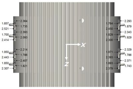
Figure 11.
Mean velocities at the inlet nozzle, final time of the simulation (top view, unit: m/s).
3.4. Validation of Numerical Data
In Figure 12, the vertical axis at the center is plotted on the temperature for the last one of Figure 8 and Figure 10 at 840 s. As we had no measures data for the prototype CANDU-6, the temperature distribution is normalized with the reduced-scale model test [14], and compared with other methods of computation as well as a set of coarse but experimental data: the numerical data from ANSYS-CFX, and MODTURC-CLAS [5,6], etc. Although position and temperature are normalized, the circulating flow derived from buoyancy force reaches the equilibrium of maximum temperature at 0.25 < y/D < 0.3.
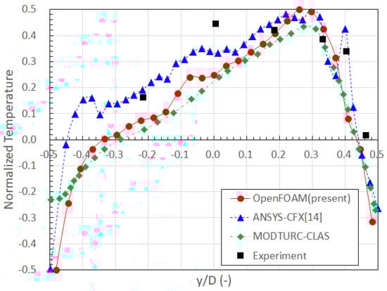
Figure 12.
Validation of numerical data with other codes and experiment for the normalized temperature distribution along the vertical axis.
4. Conclusions
A prototype of CANDU-6 reactor is numerically analyzed around a three-dimensional moderator flow in calandria tank with OpenFOAM, an open-source CFD code. The three-dimensional shape including 380 rods in the calandria tank is precisely modeled without porous approximation to avoid parasite errors. The buoyancy term in the incompressible Navier-Stokes equation is considered with Boussinesq approximation of the temperature variation. Turbulence effect is reflected to energy equation as well as momentum equation with the realizable k-ε model.
The computational result shows that there should be no steady solution about the circulation flow, and therefore the unsteady simulation is achieved after getting a quasi-steady with oscillation of flow properties. The flow field is not converged to a steady solution. Instead, it oscillates in the regime of quasi-steady state. After 12,000 iterations from initial condition to the quasi-steady state, the unsteady simulation within 840 s shows no evidence of exact periodic oscillation for physical properties. The observation for 225 s, an approximate period of flow pattern, presents a complex structure of turbulent mixing despite uncertainties originated from the high intensity of turbulence. There are no regions where the temperature rises more than 90 degrees Celsius due to very slow transferring flow. Most of computational region marks the velocity less than 1 m/s. As the inlet nozzle flow going down from the stagnation point, it is highly diffused with the pressure drop due to the calandria tubes. Turbulent eddies were found in the temperature field, continuously developing to merge or separate at the interface of hot and cool fluid. The dimensionless wall distance of the first grid from wall, y+ was checked as less than 80 in the most of computational domain but should be reduced with finer grids free of wall functions, especially for the outer wall of calandria tank.
Overall, this research presents that the use of open-source software is also very feasible for the application of analysis on the moderator system of PHWR such as CANDU-6. Compared with other commercial codes, the equivalent computation could be obtained from cheaper price and free copyright. However, the use of CFD alone provides a limited perspective. In practice, the CFD boundary condition should be supported by system analysis for possible transient phenomena.
Author Contributions
Conceptualization, H.T.K. and S.-M.C.; Methodology, S.-M.C.; Software, S.-M.C.; Validation, H.T.K., S.-M.C. and Y.W.S.; Formal Analysis, Y.W.S.; Investigation, H.T.K.; Resources, H.T.K.; Data Curation, H.T.K. and S.-M.C.; Writing—Original Draft Preparation, H.T.K.; Writing—Review & Editing, S.-M.C.; Visualization, S.-M.C.; Supervision, S.-M.C.; Project Administration, S.-M.C.; Funding Acquisition, H.T.K.
Funding
This work was supported by the National Research Foundation of Korea (NRF) grant funded by the Korea government (Ministry of Science, ICT, and Future Planning) (No. NRF-2016R1D1A3-B01015543), and the Human Resources Development Program (Grant No. 20174010201350) of the Korea Institute of Energy Technology Evaluation and Planning (KETEP) grants funded by the Korea government (Ministry of Trade, Industry, and Energy).
Conflicts of Interest
The authors declare no conflict of interest. The funders had no role in the design of the study; in the collection, analyses, or interpretation of data; in the writing of the manuscript, and in the decision to publish the results.
References
- Wolsong Units. 2/3/4 Final Safety Analysis Report; Korea Electric Power Corporation: Naju, Korea, 1995; Chapter 15. [Google Scholar]
- Gillespie, G.E. An Experimental Investigation of Heat Transfer from a Reactor Fuel Channel: To Surrounding Water. In Proceedings of the 2nd Annual Conf. Canadian Nuclear Society, Ottawa, ON, Canada, 10 June 1981. [Google Scholar]
- Fan, H.Z.; Aboud, R.; Neal, P.; Nitheanandan, T. Enhancement of the Moderator Subcooling Margin using Glass-peened Calandria Tubes in CANDU Reactors. In Proceedings of the 30th Annual Conference of the Canadian Nuclear Society, Calgary, AB, Canada, 31 May–3 June 2009. [Google Scholar]
- Huget, R.G.; Szymanski, J.; Midvidy, W. Status of Physical and Numerical Modelling of CANDU Moderator Circulation. In Proceedings of the 10th Annual Conference of the Canadian Nuclear Society, Ottawa, ON, Canada, 4–7 June 1989. [Google Scholar]
- Huget, R.G.; Szymanski, J.; Galpin, P.F.; Midvidy, W.I. MODTURC-CLAS: An Efficient Code for Analyses of Moderator Circulation in CANDU Reactors. In Proceedings of the 3rd International Conference on Simulation Methods in Nuclear Engineering, Montreal, QC, Canada, 18–20 April 1990. [Google Scholar]
- Khartabil, H.F.; Inch, W.W.; Szymanski, J.; Novog, D.; Tavasoli, V.; Mackinnon, J. Three-dimensional moderator circulation experimental program for validation of CFD code MODTURC_CLAS. In Proceedings of the 21th CNS Nuclear Simulation Symposium, Ottawa, ON, Canada, 24–26 September 2000. [Google Scholar]
- Kim, H.T.; Rhee, B.W. Scaled-down moderator circulation test facility at Korea Atomic Energy Research Institute. Sci. Technol. Nucl. Install. 2016, 2016, 5903602. [Google Scholar] [CrossRef]
- Im, S.; Kim, H.T.; Rhee, B.W.; Sung, H.J. PIV measurement of the flow patterns in a CANDU-6 model. Ann. Nucl. Eng. 2016, 98, 1–11. [Google Scholar] [CrossRef]
- Hadaller, G.I.; Fortman, R.A.; Szymanski, J.; Midvidy, W.I.; Train, D.J. Frictional Pressure Drop for Staggered and In Line Tube Bank with Large Pitch to Diameter Ratio. In Proceedings of the 17th Annual Conference of the Canadian Nuclear Society, Fredericton, NB, Canada, 9–12 June 1996. [Google Scholar]
- Yoon, C. Development of a CFD Model for the CANDU-6 Moderator Analysis Using a Coupled Solver. Ann. Nucl. Eng. 2007, 35, 1041–1049. [Google Scholar] [CrossRef]
- Sarchami, A.; Ashgriz, N.; Kwee, M. Three Dimensional Numerical Simulation of a Full Scale CANDU Reactor Moderator to Study Temperature Fluctuations. Int. J. Eng. Phys. Sci. 2012, 6, 275–281. [Google Scholar] [CrossRef]
- Teyssedou, A.; Necciari, R.; Reggio, M.; Zadeh, F.M.; Étienne, S. Moderator Flow Simulation around Calandria Tubes of CANDU-6 Nuclear Reactors. Eng. Appl. Comput. Fluid Mech. 2014, 8, 178–192. [Google Scholar] [CrossRef]
- Gim, G.H.; Chang, S.M.; Lee, S.; Jang, G. Fluid-Structure Interaction in a U-Tube with Surface Roughness and Pressure Drop. Nucl. Eng. Technol. 2014, 46, 633–640. [Google Scholar] [CrossRef]
- Kim, H.T.; Chang, S.M. Computational Fluid Dynamics Analysis of the Canadian Deuterium Uranium Moderator Tests at the Stern Laboratories Inc. Nucl. Eng. Technol. 2015, 47, 284–292. [Google Scholar] [CrossRef]
- OpenFOAM User Guide; CFD Direct Ltd.: 2019. Available online: https://openfoam.com/documentation/user-guide/ (accessed on 20 January 2019).
- Kim, H.; Chang, S.M.; Shin, J.H.; Kim, Y.G. The Feasibility of Multidimensional CFD Applied to Calandria System in the Moderator of CANDU-6 PHWR Using Commercial and Open-Source Codes. Sci. Technol. Nucl. Install. 2016, 2016, 3194839. [Google Scholar] [CrossRef]
- Hanna, B.N. CATHENA: A thermalhydraulic code for CANDU analysis. Nucl. Eng. Des. 1998, 180, 113–131. [Google Scholar] [CrossRef]
- Seo, Y.S.; Chang, S.M.; Yeom, G.S. CFD Analysis on the Validation Experiment with MCT 1/4 Model; KAERI Report; Mirae Engineering Co.: Jeonju, Jeonbuk, Korea, 2015. [Google Scholar]
- Kim, H.T.; Chang, S.M. OpenFOAM Analysis of CANDU-6 Moderator Flow. In Proceedings of the Transactions of the Korean Nuclear Society Autumn Meeting, Gyeongju, Korea, 29–30 October 2015. [Google Scholar]


© 2019 by the authors. Licensee MDPI, Basel, Switzerland. This article is an open access article distributed under the terms and conditions of the Creative Commons Attribution (CC BY) license (http://creativecommons.org/licenses/by/4.0/).