Article

Analysis of a Control System for DFIG Wind Generators Based on the Transmission of Power References through a GSM Wireless Network: A Smart Grid Experimental Approach

by
Luis A. G. Gomez
1,
Samuel C. Pereira
2,*,
André L. L. F. Murari
3,
Henrique S. Franco
3,
Jose A. T. Altuna
3,
Mauricio B. C. Salles
1,
Alfeu J. S. Filho
3,
Carlos E. Capovilla
3 and
Ivan R. S. Casella
3
1
Laboratory of Advanced Electric Grids (Polytechnic School), University of São Paulo (USP), São Paulo 05508-010, Brazil
2
Department of Automation and Process Control, Federal Institute of São Paulo (IFSP Suzano), São Paulo 08673-010, Brazil
3
Center for Engineering, Modeling and Applied Social Sciences (CECS), Federal University of ABC (UFABC), Santo André 09210-580, Brazil
*
Author to whom correspondence should be addressed.
Energies 2019, 12(2), 241; https://doi.org/10.3390/en12020241
Submission received: 26 October 2018 / Revised: 16 December 2018 / Accepted: 27 December 2018 / Published: 14 January 2019
(This article belongs to the Special Issue Sustainable Energy Systems)

Abstract

:
This work proposes the use of the automatic Short Message Service (SMS) of a Global System for Mobile Communication (GSM) network to transmit the control information to a Doubly Fed Induction Generator (DFIG) of a wind turbine, according to the Smart Grid (SG) concept. In the proposed strategy, the Control Center (CC) can remotely transmit the required power references (active and reactive) to the DFIG controller, in order to manage the power generation of the wind turbine dynamically. The proposed wireless network was developed in a Software Defined Radio (SDR) transceiver connected to an OpenBTS platform. The control information can be directly inserted in the Open Base Transceiver Station (OpenBTS) server (located at the CC) or sent by a wireless device (e.g., mobile phone) connected to the GSM network, and then transmitted to the wireless receiver at the wind turbine. The receiver on the turbine side was developed in a microcontroller board with a GSM card, and the DFIG controller was implemented in a Digital Signal Processor (DSP) board. The results of the tests showed that the DFIG can be satisfactorily controlled according to the power references, considering that they vary at low rates.

1. Introduction

Power grids are experiencing significant changes in both infrastructure and operation, due to the introduction and deployment of the Smart Grid (SG) concept [1]. In addition, the use of renewable sources for electricity generation (such as photovoltaic and wind) is constantly increasing, mainly due to societal concerns regarding high CO 2 emission levels and global warming [2,3]. Considering this new scenario, SG requires sophisticated communication and power electronic integrated solutions for monitoring, controlling, and connecting the different energy sources in an efficient way [4,5].
Regarding the use of wind energy, an interesting solution is the use of Doubly Fed Induction Generators (DFIGs) connected to the grid [6,7,8,9]. This type of machine presents some important advantages, such as operation in four quadrants and processing of only 25% to 30% of its nominal power by the converter, while other electrical machines, such as the Switched Reluctance Generator (SRG), Squirrel Cage Induction Generator (SCIG), and Synchronous Generator (SyG) process full power by the converter [10,11,12].
In a traditional DFIG scheme, a back-to-back converter connects the rotor of the generator to the power grid, while the stator is directly connected to the main grid [13,14]. The converter enables power flow between the DFIG and the grid by applying three-phase voltage on the rotor side [15]. In addition, the converter connected to the grid controls the DC link and enables the absorption or injection of power to the grid, in accordance with the DFIG speed. The performance of the power flow can be increased by using control strategies, such as Stator Flux Oriented (SFO) or Stator Voltage Oriented (SVO) [12]. These strategies allow the control of active (P) and reactive (Q) powers of the stator that are injected into the grid by adjusting the rotor current, by means of Proportional Integral (PI) [16], predictive [17], deadbeat [7,18], or sliding mode [19] controllers.
On the other hand, wireless communication technologies have become quite popular in power system applications in the last decade [19,20,21]. This trend is explained by their increasing reliability, reduced cost, easy maintenance, high speed, and flexibility of connection between different devices [22,23,24,25]. In the literature, it is possible to find several studies about wireless systems in the control of renewable energy systems [10,26,27,28,29,30,31]. Despite the inherent difficulties of transmitting signals through wireless channels such as noise, interferences, and multipath fading, the use of wireless systems has become increasingly attractive, especially with the materialization of the SG [32].
In this context, this work analyzes the performance of a DFIG power control system, considering that the power references are transmitted from the SG Control Center (CC) to the wind generator by a mobile communication network infrastructure, as shown in Figure 1. In order to reduce the implementation time and operation costs of the wireless control system, it is proposed and adopted to use the automatic Short Message Service (SMS) of a Global System for Mobile Communication (GSM) network to transmit the power references.
SMS is a wireless, bi-directional, low data rate transmission technique employed by all 2G (second generation), 3G (third generation), and 4G (fourth generation) mobile communication systems, which has been considered for use in different power systems applications. For instance, in [33], an SMS-based control system for home appliances using GSM technology, without accessing the local network, was presented.
In [34], authors proposed the use of the GSM network as an option for SG communication infrastructure, in order to control thousands of mobile Plug-in Electric Vehicles (PEV) chargers, using a simple SMS interface. At certain times of the day, charging large numbers of PEV may result in overloading sections of the electric power grid. However, the SG can use SMS messages to delay charging or regulate charging rates, allowing the existing power system to handle the increased load without having to increase the peak power capacity of feeders or add generation. In [35], a Smart Load Management (SLM) system is presented, to be effectively utilized to meet emergency customer demands (light and fan) when power generation is not sufficient for the current demand. The connectivity is provided by a GSM-based mobile network. The SLM device can configure and control loads by SMS, without changing hardware or software.
In the proposed system, a 2G GSM network infrastructure was chosen to send the control information to the wind generator via SMS, due to its simplicity of development, wide coverage, and low operation cost (in the USA, unlimited SMS packages can cost around a few dollars per month). This GSM infrastructure was developed using a Software Defined Radio (SDR) transceiver connected to an Open Base Transceiver Station (OpenBTS) platform. The control information can be directly inserted into the OpenBTS server (located at the CC), or sent by a wireless device (e.g., mobile phone) connected to the GSM network, and then transmitted to the wireless receiver at the wind turbine. The receiver on the turbine side was developed in a microcontroller board with a GSM card, and the DFIG controller was implemented in a Digital Signal Processor (DSP) board. To the best of our knowledge, this is the first work proposing this strategy to transmit power control references to wind generators.
In addition to this introductory section, this work is organized as follows: Section 2 briefly describes the fundamental equations for the DFIG and the adopted control strategy. Section 3 discusses the mobile communication infrastructure employed in the experimental tests. The practical implementation of the proposed system and corresponding evaluation tests are shown and discussed in Section 4. Finally, the main conclusions are presented in Section 5.

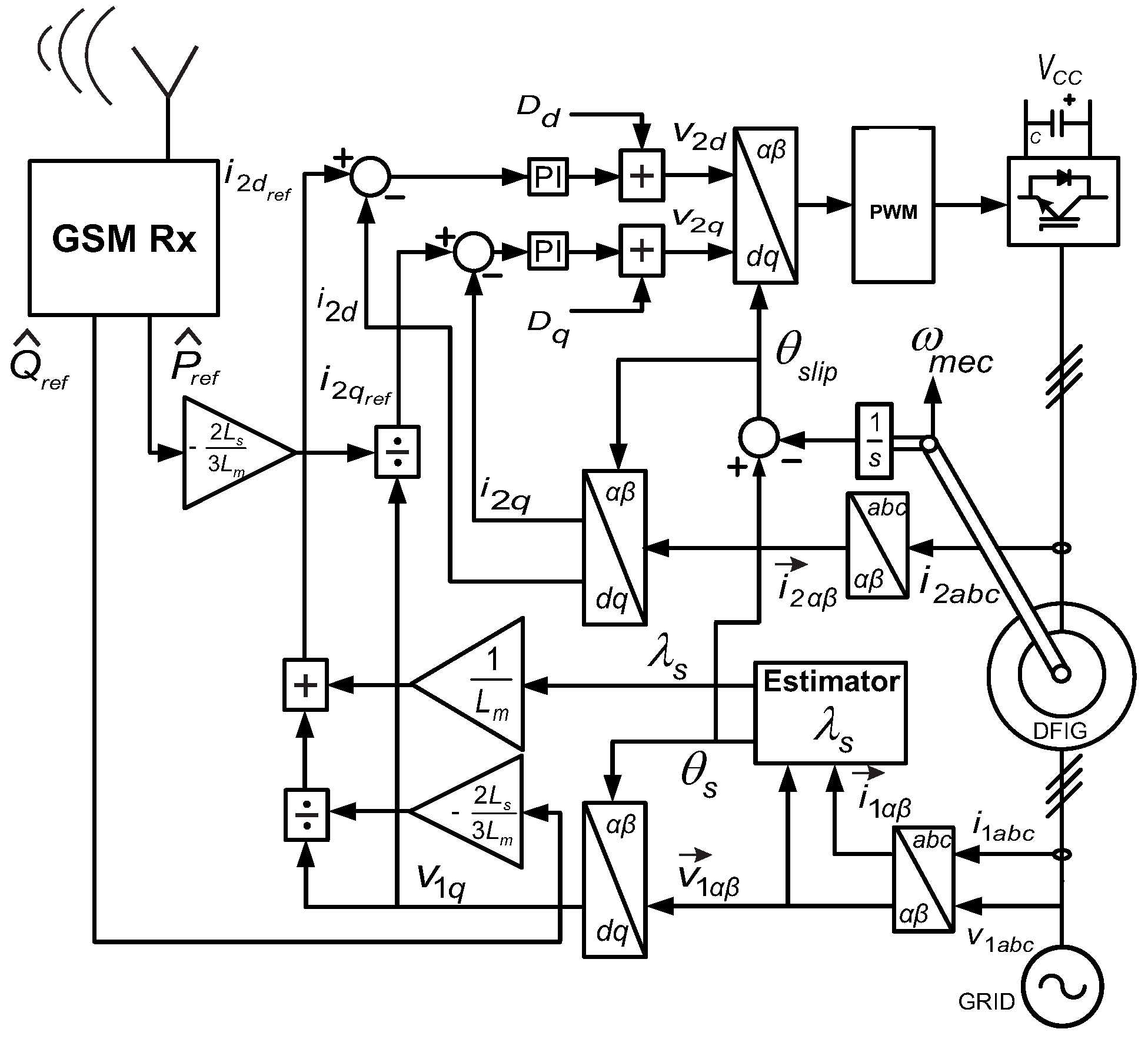
2. DFIG Model and Vector Control

The DFIG control operation is traditionally implemented by a vector control technique [12,36,37], which allows to control the stators P and Q separately, by means of the rotor current components (direct, i 2 d , and quadrature, i 2 q ) in the stator flux reference frame, obtained by:
P = 3 2 v 1 L M L 1 i 2 q , and
Q = 3 2 v 1 λ s L 1 L M L 1 i 2 d ,
where v 1 = v 1 q = | v 1 d q | , λ s is the stator flux linkage, L 1 and L M are the proper and mutual inductances, respectively, and the subscripts 1 and 2 represent the stator and rotor parameters, respectively.
Observing these equations, it is verified that the rotor currents will reflect at P and Q, and, consequently (by using this principle), it is possible to implement DFIG power control. The detailed block diagram of the adopted DFIG controller, using PI controllers, is shown in Figure 2.
In addition, the components of the rotor voltage vector are obtained by the PI controllers, in which the processing of rotor current errors occurs, being represented by
v 2 d = i 2 d r e f i 2 d k p + k i s ω s l L 2 + L M 2 L 1 i 2 q D d
and
v 2 q = i 2 q r e f i 2 q k p + k i s + ω s l L 2 + L M 2 L 1 i 2 d + L M L 1 λ s D q ,
where ω s l is the slip speed, k p is the proportional gain, k i is the integral gain, L 2 is the rotor inductance, and s is the Laplace operator.
For P control, the rotor current reference, using (1), is given by
i 2 q r e f = 2 P ^ r e f L 1 3 v 1 L M ,
and for Q control, by using (2), the rotor current reference is given by
i 2 d r e f = 2 Q ^ r e f L 1 3 v 1 L M + λ s L M ,
where P ^ r e f and Q ^ r e f are the respective power references at the output of the wireless receiver on the wind generator.

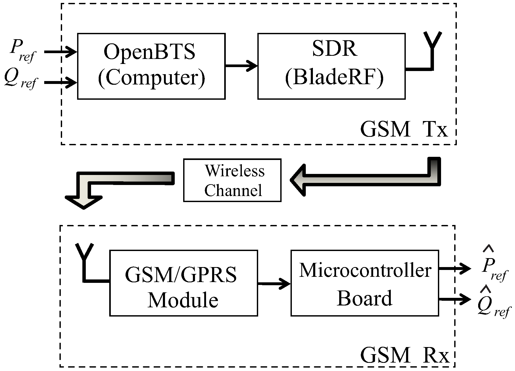
3. Mobile Communication Infrastructure and SMS

In this work, a GSM network infrastructure is used to transmit power references through a wireless channel. GSM is the most widespread worldwide 2G mobile communication standard. Despite the high penetration of the new 3G and 4G standards, it is still widely employed to offer voice services in remote locations and low and medium data rate services (e.g., wireless credit card machines) with wide coverage and low cost.
GSM employs a Gaussian Minimum Shift Keying (GMSK) modulation scheme and multiplexes user transmissions in time and frequency by means of Time Division Multiple Access (TDMA) and Frequency Division Multiple Access (FDMA) techniques. In short, a user’s voice call or SMS are sent and received at specific time slots (one of eight slots) and frequency channels (200 kHz of bandwidth) [38,39].
For data protection, GSM implements block interleaving and a Convolutional Coding (CONV) scheme [40], which is a Forward Error Correction (FEC) system extensively used in different wireless systems (e.g., cellular networks, wireless computer networks, space communication systems, and so on), due to its excellent relationship between error correction capability and encoding and decoding complexity [41,42]. In comparison to Turbo Coding (TC) [43,44] and Low Density Parity Check (LDPC) coding schemes [45,46,47,48], the error correction capability of CC is lower; however, it has a much smaller decoding complexity and latency [41,42,49,50], which is why CC has been used in most of the new wireless standards. The CC used on GSM varies on rates of 1/2, 1/3 and 244/456 [38,40].
The proposed wind DFIG control system uses a GSM network infrastructure to transmit the power references from the grid operator to the wind generator by means of SMS messages, which each contain up to 160 7-bit encoded characters. Since it can work on the reliable Standalone Dedicated Control Channel (SDCCH), retransmissions and acknowledges are performed in layer 2, which, in conjunction with the FEC and interleaving techniques already mentioned, assures the reliable delivery of the power references to the wind generator controller.

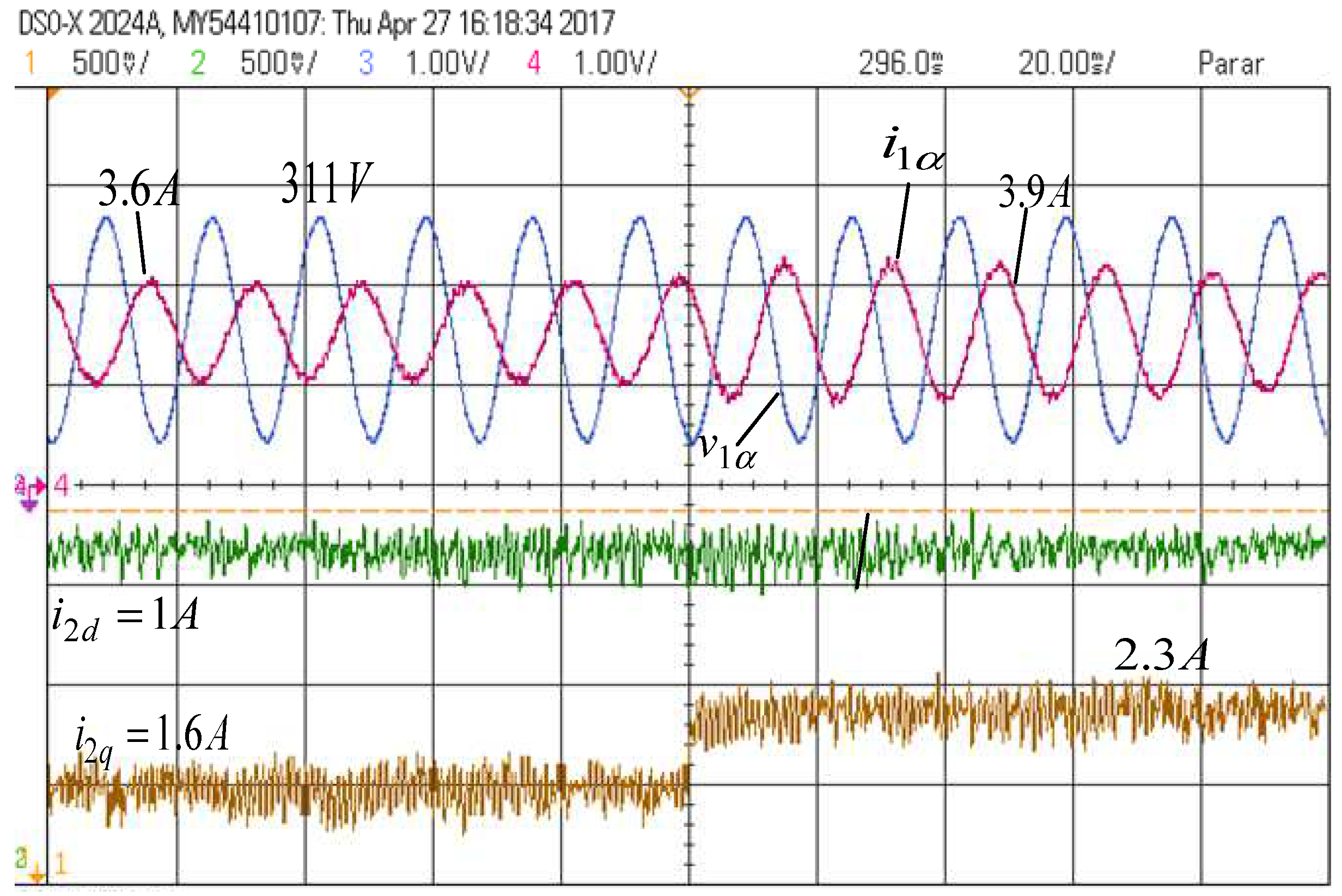
4. Practical Model, Experimental Tests and Results

This section describes the practical implementation of the proposed system, shown in Figure 3, and presents the test results.
The GSM network infrastructure was developed on the GNU Radio software (open source project) [51], version 3.7.10.1, running in a computer with Ubuntu OS (Operational System), according to the OpenBTS project, and it was connected to a BladeRF SDR board model x115, as shown in Figure 3 (at the top right corner). To address legal issues, the network is configured to operate on the Absolute Radio Frequency Channel Number (ARFCN) 975 (downlink frequency of 925.2 MHz), a valid GSM frequency within the ISM (Instrumentation, Scientific, and Medical) band.
This infrastructure can be located at the control center of the grid operator. From it, SMS messages with P ^ r e f and Q ^ r e f power references information can be sent. In the head of the messages, it is defined whether the reference information is P ^ r e f or Q ^ r e f . Each SMS message is composed of eight symbols (each one having eight bits, totaling 256 possible different levels), each one representing the power value in a 100 ms time interval. A full SMS structure is shown in Figure 4.
During the transmission process, the SMS messages containing the power references are created directly by a script running in OpenBTS (open source project) [52,53], version 4.0. After each message is sent, a sleep command is executed, resulting in a guard interval between messages. Therefore, this system is very efficient, as it is necessary to send a new message only when the power reference values change, avoiding the need for continuous transmissions.
On the other hand, the receiver system is placed at the wind generator. It is composed of a PIC18F45K22 microcontroller development board, in which a Teli G865QUAD GSM module is connected. A smart card from a cellular service operator (not enabled in the test region) is employed, which avoids any legal or testability problems for the proposed system.
During the reception process, the GSM signal is firstly demodulated and decoded. Particularly, in the GMSK demodulation process, it used four symbols and a retrace length of 16 symbols. Then, the recovered bits are grouped to determine the power reference levels transmitted, to be followed by the DFIG power control. After that, the power reference levels are proportionally converted to analog voltage levels by the internal Digital-to-Analog Converter (DAC) of the microcontroller. The DAC has 5-bit resolution with a 2.048 V reference value. These quantized levels of power reference are sent to the power control, implemented in a TMS320F28335 DSP board. The Figure 5 shows a block diagram summarizing the implemented communication system.
On the wind generator side, the Direct Torque Control (DTC) is applied to a DFIG mechanically coupled to a DC motor, which emulates the wind effect. The DFIG parameters are presented in Table 1. The DTC was implemented with a power electronic converter using Insulated-Gate Bipolar Transistors (IGBTs). The rotor speed is measured by an encoder (with 3600 pulses per revolution), and the rotor voltage commands are modulated by using symmetrical Space Vector Pulse Width Modulation (SV-PWM) with a switching frequency of 10 kHz.
In the first test, a step analysis of P ^ r e f and Q ^ r e f and the corresponding calculated rotor current references (by using (5) and (6)) is performed, according to Table 2. For this test, two messages were sent, one with P r e f kept constant at 380 W ( i 2 q r e f = 1 A), and the other with Q r e f sweeping from 1 kvar to 1.9 kvar ( i 2 q r e f from 2.3 A to 0 A), according to the pattern shown in Figure 6.
In this figure, it is possible to observe two and a half messages on the scope screen (the SMS has 8 values, with a duration of 100 ms each). This occurs intentionally, as the microcontroller is programmed to repeat the SMS message until a new one is received.
In addition, Figure 7 shows the system behavior during the change on the i 2 d (from 2.3 A to 0 A, while the i 2 q is kept constant at 1 A). The time response was 8 ms, following Q ^ r e f variation. It can be noted that the stator current changes its phase proportionally, which represents a perfect response of the implemented control system.
Observing these graphs, it is possible to notice that there is a noise with random behavior added by the communication system. However, even with the noise, the references are satisfactorily followed by the control system.
In the second test, the same procedure as the first one was performed, with the adopted reference values and their respective currents shown in Table 3. This time, Q r e f was kept constant at 1.54 kvar ( i 2 d r e f = 1 A), while P r e f swept from −610 W to −890 W ( i 2 q r e f from 1.6 A to 2.3 A), according to the pattern shown in Figure 8.
To complement the analysis, Figure 9 shows the system behavior during the i 2 q variation (from 1.6 A to 2.3 A, while i 2 d was kept constant at 1 A). The time response was only 2 ms following P variation. It is possible to observe that the references are satisfactorily followed by the DFIG control system. From the same figure, it can be verified that the stator current changes its amplitude (from 3.6 A to 3.9 A), according to the expected response of the control system. As in the first test, there is a random noise in the references, which did not compromise the system performance.
Although the tests performed have been successful, SMS messages can take seconds to be received and processed properly—which might limit their use, depending on the application. The developed wireless system was designed to operate at a low data rate. It was configured to transmit 1 power level each 100 ms (8 power levels per SMS message), but it can be configured to different rates (max. rate is 1 power level each 1 ms). In this configuration, the receiving time is on the order of 10 s, to guarantee proper management of data. This delay in consecutive transmissions is related to the implementation of the OpenBTS platform, which suffers overloads even under low transmission rates. This problem can be reduced by improving the dimensioning and processing of the OpenBTS short message output buffer (SMQueue).
Considering that the wind variations are very slow, the effects of of SMS transmissions delays in the control system can be reduced by transmitting the power references in batches and changing its time base reference (e.g., from milliseconds to seconds) and the number of power levels (e.g., 8 to 140) of each SMS message. According to the GSM standard, each short message can contain a maximum of 140 bytes of data (140 power levels). For a power profile with a granularity of 100 ms, each message can cover a power program with a duration of 14 s (1 byte to represent the power level results in 255 different levels). Thus, for instance, if the granularity is changed to 2 s, instead of 100 ms, a SMS message could cover a time period of approximately 5 min (4.7 min) and the wait intervals between SMS sending would become less relevant, since, in this interval, several SMS messages will be sent for adjustments. The downside of this solution is a reduction in the temporal granularity of the transmitted control information.
For applications that require a reduced latency and/or a higher transmission rate, the General Packet Radio Service (GPRS), the Enhanced Data rates for GSM (EDGE), or even the data services of the 3G and 4G networks can be considered. However, these solutions may be much more expensive (compared to the GSM’s SMS), which contradicts the purpose of this study: To analyze a simple low-cost wireless remote control solution.

5. Conclusions

This paper presented an experimental analysis of a DFIG-based wind turbine control system that receives power references from the grid operator, by means of a GSM network (a consolidate wireless communication standard). Using SMS to transmit the references (each one with two messages, P r e f and Q r e f ), two tests were performed: A first one using Q r e f steps with P r e f constant, and another one using P r e f steps with Q r e f constant. The test results showed that the DFIG controllers satisfactorily followed the received references, and that the noise introduced by the wireless communication system did not affect the control system’s performance. The results are in agreement to a control without wireless reference transmissions, which validates the proposed system.
Due to its flexibility and reliability of information, the implemented system is an interesting solution—it offers a significant reduction in deployment and operating costs of a communication system for the implementation of the SG concept in wind power generation systems. Moreover, looking to a more traditional implementation, the proposed configuration can be used as a secondary communication link, implementing redundancy in order to improve the system security.
As a complementary and future proposal, a 3G LTE (Long Term Evolution) network infrastructure may also be employed, reducing the transmission delay at the expense of increasing operation costs and power consumption of equipments and devices [54].

Author Contributions

Conceptualization, M.B.C.S., A.J.S.F., C.E.C., and I.R.S.C.; methodology, J.A.T.A.; software, L.A.G.G., S.C.P., A.L.L.F.M., and H.S.F.; validation, J.A.T.A., M.B.C.S., and I.R.S.C.; formal analysis, J.A.T.A. and M.B.C.S.; investigation, L.A.G.G., S.C.P., A.L.L.F.M., and H.S.F.; resources, M.B.C.S., A.J.S.F., and I.R.S.C.; data curation, L.A.G.G., S.C.P., A.L.L.F.M., and H.S.F.; writing—original draft preparation, L.A.G.G., S.C.P., and A.L.L.F.M.; writing—review and editing, I.R.S.C.; visualization, I.R.S.C., L.A.G.G., and S.C.P.; supervision, M.B.C.S., A.J.S.F., C.E.C., and I.R.S.C.; project administration, A.J.S.F., C.E.C., and I.R.S.C.; funding acquisition, M.B.C.S., A.J.S.F., and I.R.S.C.

Funding

Research funded by CAPES, CNPq (405757/2018-2), and FAPESP (2017/04623-3).

Conflicts of Interest

The authors declare no conflict of interest.

References

  1. Xu, Y.; Yang, Z.; Gu, W.; Li, M.; Deng, Z. Robust Real-Time Distributed Optimal Control Based Energy Management in a Smart Grid. IEEE Trans. Smart Grid 2017, 8, 1568–1579. [Google Scholar] [CrossRef]
  2. Bottaccioli, L.; Estebsari, A.; Pons, E.; Bompard, E.; Macii, E.; Patti, E.; Acquaviva, A. A Flexible Distributed Infrastructure for Real-Time Cosimulations in Smart Grids. IEEE Trans. Ind. Inform. 2017, 13, 3265–3274. [Google Scholar] [CrossRef] [Green Version]
  3. Wazid, M.; Das, A.K.; Kumar, N.; Rodrigues, J.J.P.C. Secure Three-Factor User Authentication Scheme for Renewable-Energy-Based Smart Grid Environment. IEEE Trans. Ind. Inform. 2017, 13, 3144–3153. [Google Scholar] [CrossRef]
  4. Kong, P.Y.; Liu, C.W.; Jiang, J.A. Cost-Efficient Placement of Communication Connections for Transmission Line Monitoring. IEEE Trans. Ind. Electron. 2017, 64, 4058–4067. [Google Scholar] [CrossRef]
  5. Sakurama, K.; Miura, M. Communication-Based Decentralized Demand Response for Smart Microgrids. IEEE Trans. Ind. Electron. 2017, 64, 5192–5202. [Google Scholar] [CrossRef]
  6. Ammar, M.; Ammar, M.E. Enhanced Flicker Mitigation in DFIG-Based Distributed Generation of Wind Power. IEEE Trans. Ind. Inform. 2016, 12, 2041–2049. [Google Scholar] [CrossRef]
  7. Costa, F.F.; Filho, A.J.S.; Capovilla, C.E.; Casella, I.R.S. Morphological filter applied in a wireless deadbeat control scheme within the context of smart grids. Electr. Power Syst. Res. 2014, 107, 175–182. [Google Scholar] [CrossRef]
  8. Marques, G.D.; Iacchetti, M.F. A Self-Sensing Stator-Current-Based Control System of a DFIG Connected to a DC-Link. IEEE Trans. Ind. Electron. 2015, 62, 6140–6150. [Google Scholar] [CrossRef]
  9. Mohammadpour, H.A.; Santi, E. Modeling and Control of Gate-Controlled Series Capacitor Interfaced With a DFIG-Based Wind Farm. IEEE Trans. Ind. Electron. 2015, 62, 1022–1033. [Google Scholar] [CrossRef]
  10. Capovilla, C.; Casella, I.; Filho, A.J.S.; Barros, T.; Ruppert, E. Performance of a Direct Power Control System Using Coded Wireless OFDM Power Reference Transmissions for Switched Reluctance Aerogenerators in Smart Grid Scenario. IEEE Trans. Ind. Electron. 2015, 62, 52–61. [Google Scholar] [CrossRef]
  11. Merabet, A.; Tanvir, A.A.; Beddek, K. Speed control of sensorless induction generator by artificial neural network in wind energy conversion system. IET Renew. Power Gener. 2016, 10, 1597–1606. [Google Scholar] [CrossRef]
  12. Abad, G.; Lopez, J.; Rodriguez, M.A.; Marroyo, L.; Iwanski, G. Doubly Fed Induction Machine: Modeling and Control for Wind Energy Generation Application; Wiley-IEEE Press: Piscataway, NJ, USA, 2011. [Google Scholar]
  13. Luna, A.; Lima, F.K.A.; Santos, D.; Rodriguez, P.; Watanabe, E.H.; Arnaltes, S. Simplified Modeling of a DFIG for Transient Studies in Wind Power Applications. IEEE Trans. Ind. Electron. 2011, 58, 9–20. [Google Scholar] [CrossRef] [Green Version]
  14. Marques, G.D.; Iacchetti, M.F. Sensorless Frequency and Voltage Control in the Stand-Alone DFIG-DC System. IEEE Trans. Ind. Electron. 2017, 64, 1949–1957. [Google Scholar] [CrossRef]
  15. Taveiros, F.E.V.; Barros, L.S.; Costa, F.B. Back-to-back converter state-feedback control of DFIG (doubly-fed induction generator)-based wind turbines. Energy 2015, 89, 896–906. [Google Scholar] [CrossRef]
  16. Murari, A.L.L.F.; Altuna, J.A.T.; Jacomini, R.V.; Osorio, C.M.R.; Chaves, J.S.S.; Sguarezi Filho, A.J. A Proposal of Project of PI controller gains used on the Control of Doubly-Fed Induction Generators. IEEE Latin Am. Trans. 2017, 15, 173–180. [Google Scholar] [CrossRef]
  17. Gonçalves, P.F.C.; Cruz, S.M.A.; Abadi, M.B.; Caseiro, L.M.A.; Mendes, A.M.S. Fault-tolerant predictive power control of a DFIG for wind energy applications. IET Electr. Power Appl. 2017, 11, 969–980. [Google Scholar] [CrossRef]
  18. Almeida, L.A.L.; Sguarezi Filho, A.J.; Capovilla, C.E.; Casella, I.R.S.; Costa, F.F. An impulsive noise filter applied in wireless control of wind turbines. Renew. Energy 2016, 86, 347–353. [Google Scholar] [CrossRef]
  19. Young, K.D.; Utkin, V.I.; Ozguner, U. A control engineer’s guide to sliding mode control. IEEE Trans. Control Syst. Technol. 1999, 7, 328–342. [Google Scholar] [CrossRef]
  20. Celli, G.; Ghiani, E.; Pilo, F.; Soma, G.G. Reliability assessment in smart distribution networks. Electr. Power Syst. Res. 2013, 104, 164–175. [Google Scholar] [CrossRef]
  21. Neuzil, J.; Kreibich, O.; Smid, R. A Distributed Fault Detection System Based on IWSN for Machine Condition Monitoring. IEEE Trans. Ind. Inform. 2014, 10, 1118–1123. [Google Scholar] [CrossRef]
  22. Liu, T.; Liu, Y.; Mao, Y.; Sun, Y.; Guan, X.; Gong, W.; Xiao, S. A Dynamic Secret-Based Encryption Scheme for Smart Grid Wireless Communication. IEEE Trans. Smart Grid 2014, 5, 1175–1182. [Google Scholar] [CrossRef]
  23. Wang, X.; Yi, P. Security Framework for Wireless Communications in Smart Distribution Grid. IEEE Trans. Smart Grid 2011, 2, 809–818. [Google Scholar] [CrossRef]
  24. Langhammer, N.; Kays, R. Performance Evaluation of Wireless Home Automation Networks in Indoor Scenarios. IEEE Trans. Smart Grid 2012, 3, 2252–2261. [Google Scholar] [CrossRef]
  25. Niyato, D.; Wang, P. Cooperative Transmission for Meter Data Collection in Smart Grid. IEEE Commun. Mag. 2012, 50, 90–97. [Google Scholar] [CrossRef]
  26. Rehmani, M.H.; Reisslein, M.; Rachedi, A.; Erol-Kantarci, M.; Radenkovic, M. Guest Editorial Special Section on Smart Grid and Renewable Energy Resources: Information and Communication Technologies With Industry Perspective. IEEE Trans. Ind. Inform. 2017, 13, 3119–3123. [Google Scholar] [CrossRef]
  27. Kusiak, A.; Verma, A.; Wei, X. Wind Turbine Frontier from SCADA. Wind Syst. Mag. 2012, 3, 36–39. [Google Scholar]
  28. Cai, L.X.; Liu, Y.; Luan, T.H.; Shen, X.; Mark, J.W.; Poor, H.V. Sustainability Analysis and Resource Management for Wireless Mesh Networks with Renewable Energy Supplies. IEEE J. Sel. Areas Commun. 2014, 32, 345–355. [Google Scholar] [CrossRef] [Green Version]
  29. Zhang, W.; Wong, S.C.; Tse, C.K.; Chen, Q. Design for Efficiency Optimization and Voltage Controllability of Series-Series Compensated Inductive Power Transfer Systems. IEEE Trans. Power Electron. 2014, 29, 191–200. [Google Scholar] [CrossRef]
  30. Adamowicz, M.; Strzelecki, R.; Krzeminski, Z.; Szewczyk, J.; Lademan, L. Application of Wireless Communication to Small WECS with Induction Generator. In Proceedings of the MELECON 2010—15th IEEE Mediterranean Electrotechnical Conference, Valletta, Malta, 26–28 April 2010; pp. 944–988. [Google Scholar]
  31. Adamowicz, M.; Strzelecki, R.; Szewczyk, J.; Lademan, L. Wireless short-range device for wind generators. In Proceedings of the BEC 2010—12th Biennial Baltic Electronics Conference, Tallinn, Estonia, 4–6 October 2010; pp. 1736–3705. [Google Scholar]
  32. Hasanzadeh, A.; Onar, O.C.; Mokhtari, H.; Khaligh, A. A Proportional-Resonant Controller-Based Wireless Control Strategy With a Reduced Number of Sensors for Parallel-Operated UPSs. IEEE Trans. Power Deliv. 2010, 25, 468–478. [Google Scholar] [CrossRef]
  33. Teymourzadeh, R.; Ahmed, S.A.; Chan, K.W.; Hoong, M.V. Smart GSM Based Home Automation System. In Proceedings of the IEEE International Conference on Systems, Process & Control, Kuala Lumpur, Malaysia, 13–15 December 2013. [Google Scholar]
  34. Hochgraf, C.; Tripathi, R.; Herzberg, S. Smart Grid Charger for Electric Vehicles Using Existing Cellular Networks and SMS Text Messages. In Proceedings of the IEEE International Conference on Smart Grid Communications, Gaithersburg, MD, USA, 4–6 October 2010. [Google Scholar]
  35. Labib Billah, M.; Islam, M.R.; Rana, G.M.S.M. Design and construction of smart load management system: An effective approach to manage consumer loads during power shortage. In Proceedings of the 2015 International Conference on Electrical Engineering and Information Communication Technology (ICEEICT), Dhaka, Bangladesh, 21–23 May 2015; pp. 1–4. [Google Scholar]
  36. Tapia, A.; Tapia, G.; Ostolaza, J.X.; Saenz, J.R. Modeling and Control of a Wind Turbine Driven Doubly Fed Induction Generator. IEEE Trans. Energy Convers. 2003, 18, 194–204. [Google Scholar] [CrossRef]
  37. Capovilla, C.E.; Casella, I.R.S.; Sguarezi Filho, A.J.; Azcue-Puma, J.L.; Jacomini, R.V.; Ruppert Filho, E. A wind energy generator for smart grid applications using wireless-coded neuro-fuzzy power control. Comput. Math. Appl. 2014, 68, 2112–2123. [Google Scholar] [CrossRef]
  38. 3GPP-3rd Generation Partnership Project, 3GPP-3rd Generation Partnership Digital Cellular Telecommunications System (Phase 2+)-Physical Layer on the Radio Path-General Description; ETSI: Sophia Antipolis, France, 2011.
  39. 3GPP-3rd Generation Partnership Project, 3GPP-3rd Generation Partnership Digital Cellular Telecommunications System (Phase 2+)-Modulation; ETSI: Sophia Antipolis, France, 2010.
  40. 3GPP-3rd Generation Partnership Project, 3GPP-3rd Generation Partnership Digital Cellular Telecommunications System (Phase 2+)-Channel Coding; ETSI: Sophia Antipolis, France, 2011.
  41. Kaiser, M.; Fong, W.; Sikora, M.; Costello, D.J. A Comparison of Decoding Latency for Block and Convolutional Codes. In Proceedings of the International Symposium on Communication Theory and Applications, Ambleside, UK, 13–17 June 2009. [Google Scholar]
  42. Lin, S.; Costello, D.J. Error Control Coding; Prentice Hall: Upper Saddle River, NJ, USA, 2004. [Google Scholar]
  43. Berrou, C.; Glavieux, A.; Thitimajshima, P. Near Shannon limit error-correcting coding and decoding: Turbo-codes. In Proceedings of the IEEE International Communications Conference, Geneva, Switzerland, 23–26 May 1993; pp. 1064–1070. [Google Scholar]
  44. Chen, J.; Abedi, A. Distributed Turbo Coding and Decoding for Wireless Sensor Networks. IEEE Commun. Lett. 2011, 15, 166–168. [Google Scholar] [CrossRef]
  45. Kim, J.; Ramamoorthy, A.; Mclaughlin, S. The design of efficiently-encodable rate-compatible LDPC codes. IEEE Trans. Commun. 2009, 57, 365–375. [Google Scholar] [CrossRef]
  46. Shuval, B.; Sason, I. On the universality of LDPC code ensembles under belief propagation and ML decoding. In Proceedings of the IEEE 26th Convention of Electrical and Electronics Engineers, Eliat, Israel, 17–20 November 2010; pp. 355–359. [Google Scholar]
  47. Yang, M.; Ryan, W.E.; Li, Y. Design of efficiently encodable moderate-length high-rate irregular LDPC codes. IEEE Trans. Commun. 2004, 52, 564–571. [Google Scholar] [CrossRef]
  48. Zhang, Y.; Ryan, W.E. Toward low LDPC-code floors: A case study. IEEE Trans. Commun. 2009, 57, 1566–1573. [Google Scholar] [CrossRef]
  49. Tahir, B.; Schwarz, S.; Rupp, M. BER Comparison Between Convolutional, Turbo, LDPC, and Polar Codes. In Proceedings of the International Conference on Telecommunications, Limassol, Cyprus, 3–5 May 2017. [Google Scholar]
  50. Arikan, E.; Hassan, N.U.; Lentmaier, M.; Montorsi, G.; Sayir, J. Challenges and some new directions in channel coding. J. Commun. Netw. 2015, 17, 328–338. [Google Scholar] [Green Version]
  51. GNU Radio Companion. Available online: https://wiki.gnuradio.org/ (accessed on 28 December 2018).
  52. A Platform for Innovation. Available online: http://openbts.org/about/ (accessed on 28 December 2018).
  53. Iedema, M. Getting Started with OpenBTS; O’Reilly Media: Sebastopol, CA, USA, 2015. [Google Scholar]
  54. Grigoreva, E.; Xu, J.; Kellerer, W. M2M wake-ups over cellular networks: over-the-top. In Proceedings of the 5th Workshop on All Things Cellular: Operations, Applications and Challenges, New York, NY, USA, 3–7 October 2016; pp. 37–42. [Google Scholar]
Figure 1. Connection between the Smart Grid (SG) Control Center (CC) and the DFIG-based wind turbine by the mobile network.
Energies 12 00241 g001
Figure 2. Block diagram of the implemented DFIG controller.
Energies 12 00241 g002
Figure 3. Practical implementation of the proposed system.
Energies 12 00241 g003
Figure 4. SMS information structure.
Energies 12 00241 g004
Figure 5. Block diagram of the communication system.
Energies 12 00241 g005
Figure 6. Q and P responses for the received references (at P constant).
Energies 12 00241 g006
Figure 7. Stator voltage and current when Q response changes.
Energies 12 00241 g007
Figure 8. P and Q responses for the received references (at Q constant).
Energies 12 00241 g008
Figure 9. Stator voltage and current when P response changes.
Energies 12 00241 g009
Table 1. DFIG nominal parameters.
ParameterSymbolValue
Total powerS3 kVA
Inertial constantJ0.05 kg·m 2
Pole pairs P P 2
Stator: [p.p.]
Voltage V 1 220 V
Current I 1 11.45 A
Resistance R 1 1 Ω
Inductance L 1 201 mH
Rotor: [p.l.]
Voltage V 2 440 V
Current I 2 4.5 A
Resistance R 2 3.13 Ω
Inductance L 2 201 mH
Mutual inductance L M 191.7 mH
Table 2. Reference values for the first test.
ReferencesSet-Point Value i 2 d ref i 2 q ref
P r e f 380 W-1 A
Q r e f 1.9 kvar0 A-
Q r e f 1 kvar2.3 A-
Q r e f 1.3 kvar1.6 A-
Table 3. Reference values for the second test.
ReferencesSet-Point Value i 2 d ref i 2 q ref
Q r e f 1.54 kvar1 A-
P r e f 0 W-0 A
P r e f −610 W-1.6 A
P r e f −890 W-2.3 A

