Article

Thermal Protection System and Thermal Management for Combined-Cycle Engine: Review and Prospects

1
School of Aerospace Engineering, Xiamen University, 422 South Siming Road, Xiamen 361005, China
2
Shenzhen Research Institute, Xiamen University, No.19, Gaoxin South 4th Road, Nanshan District, Shenzhen 518057, China
*
Author to whom correspondence should be addressed.
Energies 2019, 12(2), 240; https://doi.org/10.3390/en12020240
Submission received: 27 September 2018 / Revised: 28 December 2018 / Accepted: 3 January 2019 / Published: 14 January 2019
(This article belongs to the Section J: Thermal Management)

Abstract

:
Combined-cycle engine is a potential propulsion system for hypersonic aircraft. To ensure long-term, normal operation of combined-cycle engine under the harsh environment of high thermal load, it is of great significance to study the thermal protection and management of the propulsion system. In this study, the objective and development status of thermal protection and thermal management systems for the combined-cycle propulsion system were described. The latest research progresses of thermal protection, thermal barrier coating, and thermal management system of the combined-cycle propulsion system were summarized. Moreover, the problems and shortcoming in current researches were summarized. In addition, a prospect for the future development of thermal protection and management of the combined-cycle propulsion system was presented, pointing out a direction of great value and vital research significance to thermal protection and management of the combined-cycle propulsion system.

1. Background Introduction

1.1. Introduction to Hypersonic Aircrafts and Combined Propulsion

In 1946, Professor Hsue-shen Tsien [1] first proposed the concept of hypersonic velocity in his article Similarity Laws of Hypersonic Flows, and presented some peculiar properties of hypersonic flows. Hypersonic aircrafts generally refer to aircrafts with a Mach number greater than 5 [2]; with great military and economic values, it has become an important research topic in the field of aerospace worldwide in the 21st century. Since the 1960s when the North American X-15 [3] unveiled the era of hypersonic aircrafts (with a flying speed of 6 Ma), countries around the world, represented by the US and Russia, have researched hypersonic aircrafts and carried out a series of ground tests and flight tests. With continuous exploration and research, people’s understanding of hypersonic aircrafts has been constantly deepened, and the Mach number and flight duration of hypersonic aircrafts are also growing.
Hypersonic aircrafts put a very high requirement on their aero-engines. The mission requirements of aero-engines in the hypersonic field cannot be met by any single form of power for propulsion. Turbine engines can only work at lower Mach numbers, whereas the working Mach numbers for ramjets are relatively high [4]. Therefore, the combined-cycle propulsion (also known as combined propulsion) technology commonly used in hypersonic aircrafts can combine two or more types of propulsion system, integrate different propulsion units and functions, and adopt the most efficient type of propulsion system for different stages of flight to maximize the advantages of different propulsion, thereby greatly expanding the altitude-speed envelope of the aircraft [5]. The combined propulsion technology is an organic combination of the liquid rocket engine, turbine engine technology, and the ramjet technology. As compared to a single type of propulsion, combined propulsion features a wide range of work, a high average specific impulse, and flexible and convenient use because it can fully utilize technical advantages of different types of propulsion in their respective operating ranges. Currently, the main types of combined propulsion include rocket-based combined cycle (RBCC) propulsion, turbine-based combined cycle (TBCC) propulsion, and precooling combined propulsion [6]. RBCC is a propulsion system model that combines the advantages of the rocket motor with a high thrust-weight ratio and the ramjet with a high specific impulse [7]. Pre-cooling propulsion combination mainly refers to adding pre-cooling devices in front of traditional engines. The British SABRE engine [8] is an advanced engine device using pre-cooling combined propulsion system. TBCC refers to the power plant in which a turbine engine and other types of engines are combined [9]. A series of studies were carried out on TBCC both in the FaCAT project [10] and the RTA project [11]. The DARPA has recently conducted an AFRE study on the TBCC technology [12]. The thermal protection and management of the propulsion system of hypersonic aircrafts explored in this study were also based on the combined-cycle propulsion system model.

1.2. Thermal and Energy Management of Combined Propulsion

The thermal and energy management of combined propulsion mainly refers to the process of controlling the heat and energy of each subcomponent of combined propulsion as well as the whole system. It is of great significance to study thermal and energy management for the combined propulsion system of hypersonic aircrafts. Firstly, as hypersonic aircrafts usually fly at high Mach numbers for a long time, the propulsion system is required to function normally under harsh thermal conditions for a long period of time, enduring very high aerodynamic heating and thermal loads [13]. Therefore, it is necessary to effectively reduce the temperature of components of the propulsion system through applying technologies such as the thermal protection system, thermal management system, and thermal barrier coating on the surface of each component to ensure that the propulsion system can work normally. Secondly, the heat and energy cycle is one of the hot research topics when it comes to propulsion systems of hypersonic aircrafts [14]. The fuel needs to be heated and warmed up when entering the engine, whereas components such as the combustion chamber and air inlet need thermal protection through the active and passive cooling of the cooling system. The heat and energy of the combined propulsion can be managed by setting up a heat conduction calculation model with a small amount of calculation, designing rational oiling channels, and optimizing the heat management system and the feedback control cycle of the physical parameters, which can not only increase the fuel utilization rate by utilizing the waste heat to reduce the fuel’s quality penalty on aircrafts but also further improve the cooling capacity of the propulsion system so that it can work reliably and lastingly in hypersonic environments.

1.3. Main Works of the Present Study

In this study, the relative background and applications of hypersonic aircrafts and propulsion systems as well as the research significance of thermal and energy management were introduced. Specifically, the currently available systems of thermal and energy management of propulsion systems of hypersonic aircrafts were introduced based on the research fields of thermal protection and thermal management, and the latest research progress in these fields were summarized. doubl, the advantages and disadvantages of current researches were reviewed. Moreover, our viewpoints on the future research direction and focus of thermal protection and management of propulsion systems of hypersonic aircrafts were put forward, and a prospect on future studies was presented.

1.4. Structure of the Study

The paper consists of five sections. In Section 1, the background of hypersonic aircrafts and propulsion systems, the significance of thermal and energy management, and the main research work and framework are introduced. In Section 2, we introduce the matfig:11ure technology systems of thermal protection that have already been applied in practice as well as the latest research progress of passive thermal protection, active thermal protection, and thermal barrier coating technology. In Section 3, the application of previous thermal management technologies in propulsion system of the thermal protection is introduced, the recent research progress in the three sub-areas—i.e., the low temperature system, the thermal control system, and the thermal coupling system—is summarized, and the expected development directions of future researches are described. In Section 4, the development prospect of the thermal protection and management of propulsion systems is introduced. Finally, Section 5 sums up the entire study.

2. Thermal Protection of Combined Propulsion System

2.1. Overview

The thermal protection technology of combined propulsion mainly modifies the surface of various components of the aero-engine through manufacturing and material technologies, since special materials and structures can effectively reduce the surface temperature and improve the allowable temperature of hot components of the aero-engine. Thermal protection technology, based on the principle of thermal protection, can be divided into passive thermal protection, active thermal protection, and thermal barrier coating. Among them, passive thermal protection mainly includes the application of ceramic matrix composite (CMC) in the combustion chamber of ramjets and sharp suction pipelines [15], and the application of high silicon/phenolic materials on turbine engines and solid rocket motors [16]. Active thermal protection mainly includes the application of sweat cooling in the combustion chamber, the application of air film cooling [17] on turbine blades [18,19], and the application of convective cooling [20] in the combustion chamber and cooling channel [21]. Thermal barrier coating technology is widely used in hot components such as turbine blades, combustion chambers, and air inlets in a combined propulsion system [22]. MCrAlY (M = Ni, Co, or NiCo), a high temperature- and oxidation-resistant alloy, is mainly used as the metal adhesive layer, yttria-stabilized zirconia (YSZ) is mainly used as the ceramic thermal insulation coating in the surface layer, and the double-layer structure is usually adopted in practical applications [23,24]. Air plasma spray (APS) [25] or physical vapor deposition [26] are generally taken as the spraying process.
However, since the combined propulsion system will lead to excessively high local temperature [27] caused by huge heat load and shock wave under extreme thermophysical conditions featuring high speed, high temperature, and high combustion, it is difficult for currently available thermal protection systems to meet the cooling needs of combined propulsion system. For passive thermal protection systems, currently available materials have shortcomings when it comes to high temperature and oxidation resistance [28]. In addition, passive thermal protection systems of combined propulsion also need to bear enough mechanical loads and have excellent performance in ablation resistance, which were rarely explored in past researches [29]. For current active thermal protection systems, as the Mach number increases, the temperature of the incoming flow increases, resulting in a decline in convective cooling of the air. Nevertheless, film cooling and sweat cooling are relatively complicated, involving not only a comparatively high preparation cost but also rather difficult modeling because of the relatively complex flow environment. For the thermal barrier coating system, in the extreme high temperature environment caused by hypersonic speed, the porosity of YSZ coating will decrease, which will then lead to coating failure. Thermally grown oxide (TGO) produced between the surface layer and adhesive layer of the thermal barrier coating is not conducive to the stability of the thermal barrier coating, and due to temperature changes, misfit strain and other issues caused by differences between thermal expansion coefficients of various coatings are obvious in combined propulsion systems [30]. In view of the shortcomings of current technologies applied in combined propulsion for hypersonic aircrafts, related researches have been carried out recently on the thermal protection system, and the latest research progress was summarized in Section 2.2, Section 2.3 and Section 2.4.

2.2. Latest Research Progress of Passive Thermal Protection

In a recent study, the application of CMC as a lightweight thermal protection material for propulsion systems demonstrated significant potential [31] (Figure 1). In the HIFiRe8 project, NASA carried out experiments to test various properties of C/C-SiC and C/C materials in the high temperature environment of a ramjet combustion chamber (Figure 2) [32]. The experiment shows that the C/C-SiC material in the passive thermal protection materials used in the ramjet combustion chamber in the HIFiRe 8 project is very promising. NASA also studied the application of SiC/SiC to turbine engines [33], the results of which show that SiC/SiC is lighter in quality, has better high temperature resistance performance, and produces less oxides (NO and CO) as compared to ordinary high temperature resistance alloys. C/C material [34] can be used for the heat pipe structure at relatively sharp edges, e.g., the air inlet nozzle.
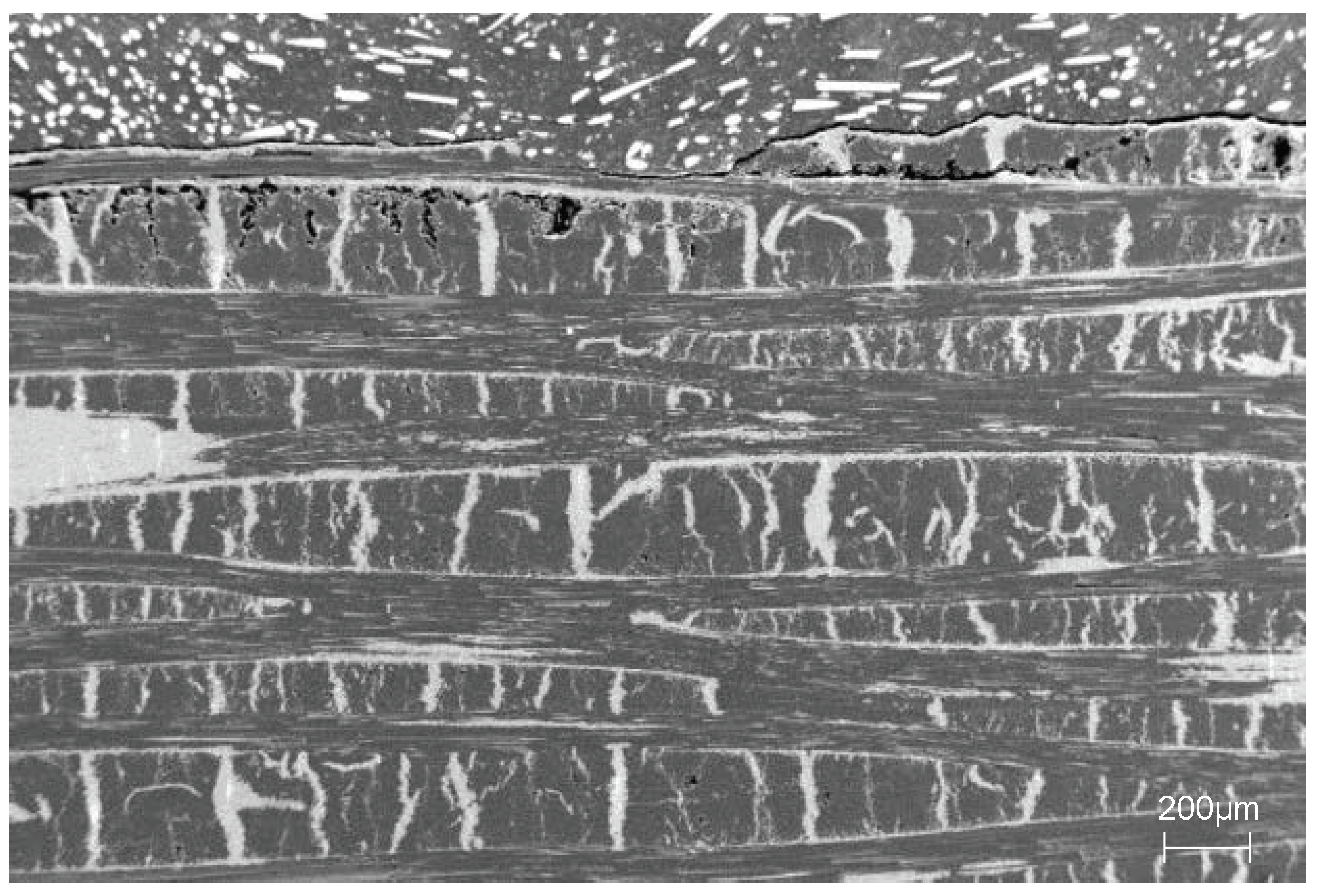
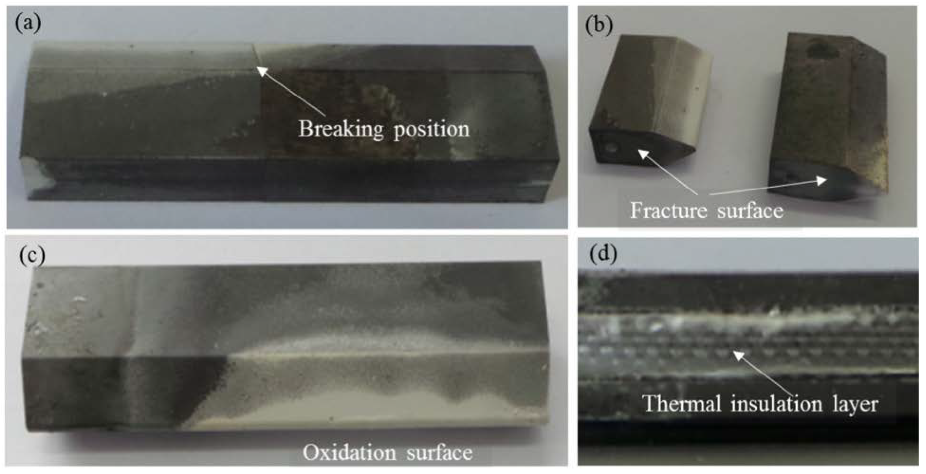
The experimental results show that C/C-SiC materials remain relatively intact at high temperature in the flight conditions of 5 and 6 Mach, with a very small degree of erosion, whereas the C/C material has a larger degree of erosion, yet it is categorized as only slight erosion. In addition, as shown in Figure 3, there are few cracks and pores in the topmost layers, which could be the result of oxidation of the carbon since close-up images show signs of oxidation in the pores at fiber ends and on the matrix. However, almost no oxidation could be found on the exposed surface of the C/C-SiC panel, which proves that C/C-SiC materials is a kind of great potential high-temperature structural material in aeronautics and astronautics with low specific weight, high specific strength, good thermal stabilty, oxidation resistance and excellent resistance to ablation.
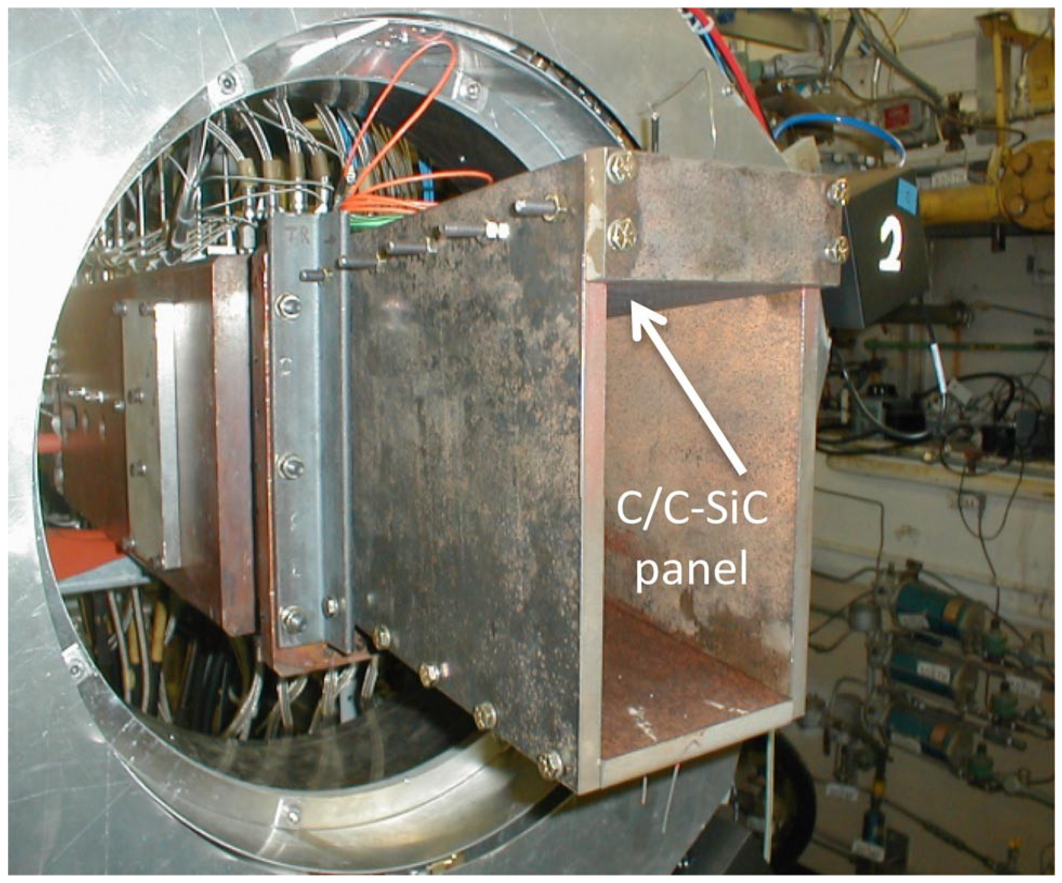
Moreover, the Langley Research Center of NASA also conducted a series of tests on CMC heat-resistant materials used in propulsion systems [35], and the experimental test equipment is shown in Figure 4. In this experiment, transient one-dimensional thermal analysis was carried out by installing thermocouples, and the maximum wall surface temperature calculated reached about 1400 C. It was also pointed out that C/C-SiC and C/C can be used as burner materials for passive scramjets during short-term test flights.
In addition to NASA, the German Space Agency also carried out a series of studies on C/C-SiC materials. According to their studies, the microstructure of C/C-SiC has high thermal conductivity in the fiber direction and its mechanical properties are better than expected [36]. The German Aerospace Center (DLR) also explored the thermal protection structure of sandwich panels made of C/SiC material [37]. Table 1 shows the relevant structure and parameters, which indicate that sandwich panels can significantly reduce the material quality, but the experiment shows that sandwich panels used in thermal protection materials have better strength and bending stiffness. Such material is suitable for propulsion system components with relatively large mechanical load, e.g., the air inlet wall and combustion chamber wall.
Current studies on passive thermal protection mainly focus on the experimental testing of a series of parameters, e.g., stability, oxidation resistance, and mechanical properties, of CMC in harsh thermal environment, yet there are few theoretical studies on the high temperature thermal behavior of CMC. It is foreseeable that with further exploration on the thermal behavior of CMC materials, there may be theoretical demonstrations of the stability of CMC materials at high temperatures, and reliable theories about thermal behavior of CMC materials will provide a reference for the selection, optimization, and structure design of new CMC materials as well as ensuring the stability of the thermal protection system in harsher thermal environments.

2.3. Latest Research Progress of Active Thermal Protection

Since renewable active thermal protection systems should usually be combined with fuel thermal management technologies [38], research progress of circulating cooling will be summarized in section where thermal management will be discussed. In this section, other active thermal protection technologies applied to propulsion systems of hypersonic aircrafts were introduced.
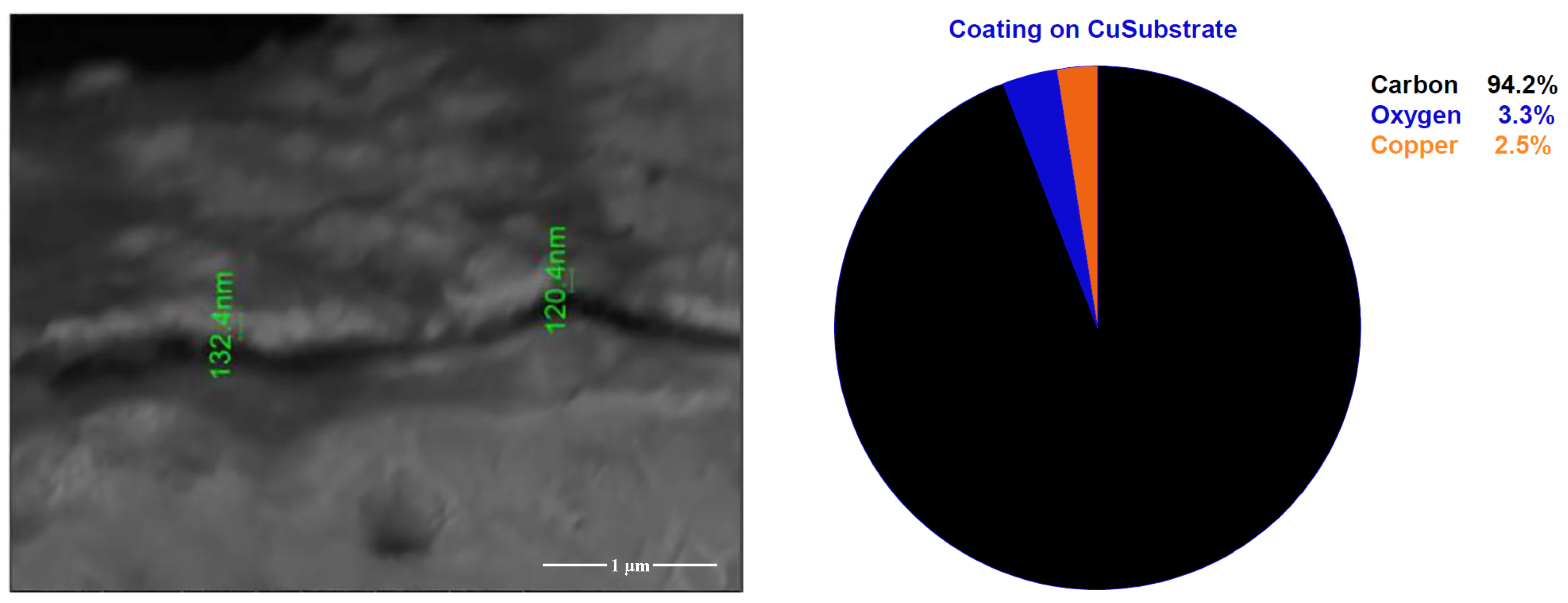
Air film cooling mainly refers to a cooling method of isolating the high-temperature fuel gas by laying out some air holes in the upper part of the cooling wall and introducing secondary airflow or fuel to form a cooled air film. Gokulakrishnan et al. [39] used an atmospheric pressure test apparatus to test the pyrolytic carbon deposition on copper alloy surfaces by analyzing the composition of the deposits based on thickness and energy spectrum of the deposits obtained by Scanning Electron Microscopy/Energy Dispersive X-Ray Spectroscopy (SEM/EDS) analysis, as shown in Figure 5, the average thickness of the deposits is estimated to be 123 nm. Gas phase testing of the fuel shows that carbon deposition is mainly formed by surface reaction of C X H X alkenes (mainly C 2 H 4 ) [40] rather than aromatic hydrocarbons in the fuel. The experimental results can mainly be used to simulate carbon deposition in air film cooling of fuel in the combustion chamber wall of the engine. However, as the experiment was carried out under atmospheric pressure, experimental results obtained under high pressure remain to be supplemented to ensure the simulation reliability.
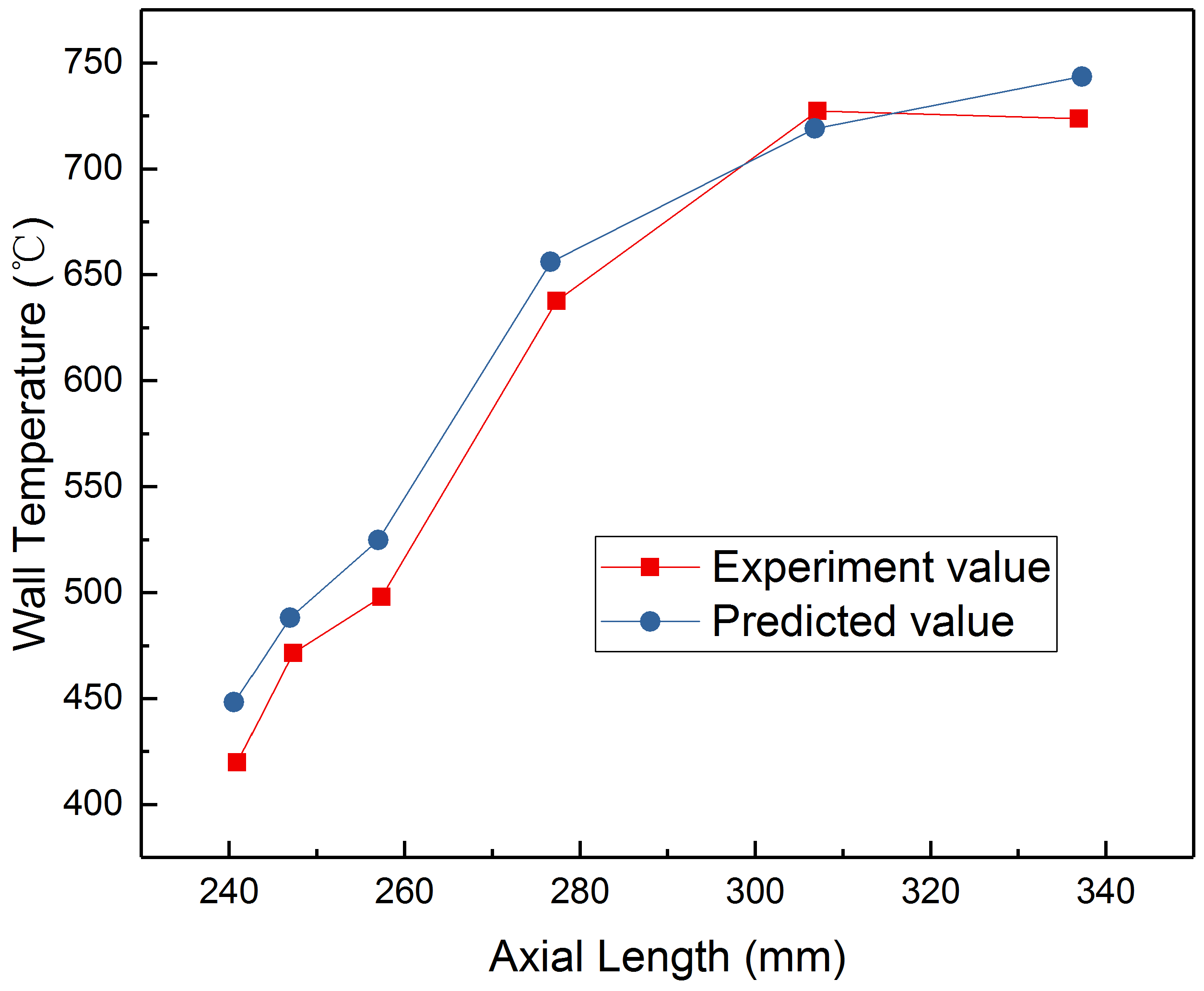
Basore et al. [41] compared the air film cooling of porous carbon (C/C) CMC and porous oxygen CMC in hypersonic flow environments. The results show that C/C CMC has the best cooling effect, and the cooling range covers the largest area downstream, which means using C/C CMC as air film cooling material for hot components, e.g., air inlet entrance and combustion chamber of the propulsion system, can achieve a relatively ideal cooling effect. In a study by Vishnu Vijayakumar [42], an experiment and calculation of air film cooling hypersonic flow environment was conducted on the exhaust nozzle of rocket engine, a stable experimental apparatus for gas film cooling experiments was established, and a preliminary study was carried out on the effect of thin film coolants. In the experiment, a CFD model combining thermal mass and chemical materials was established, and the model results were verified by experimental results of nozzle wall temperature (as shown in Figure 6), which ensured the reliability of the model. In addition, it was also concluded that a better cooling effect can be achieved if the coolant is injected into the film along the wall rather than in an oblique manner. However, as the temperature sensor of the calculation model is very sensitive to signal delay, which will probably lead to errors, the experimental model should be amended in later studies to improve the temperature measurement accuracy.
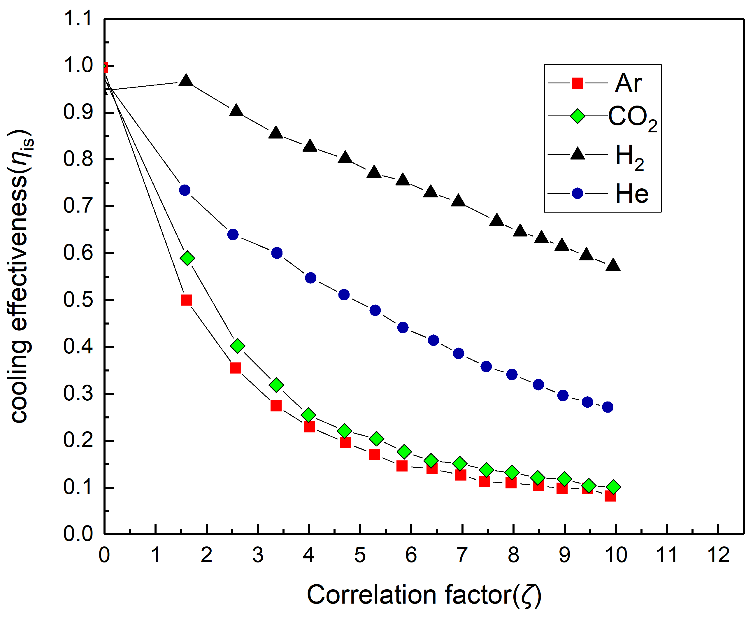
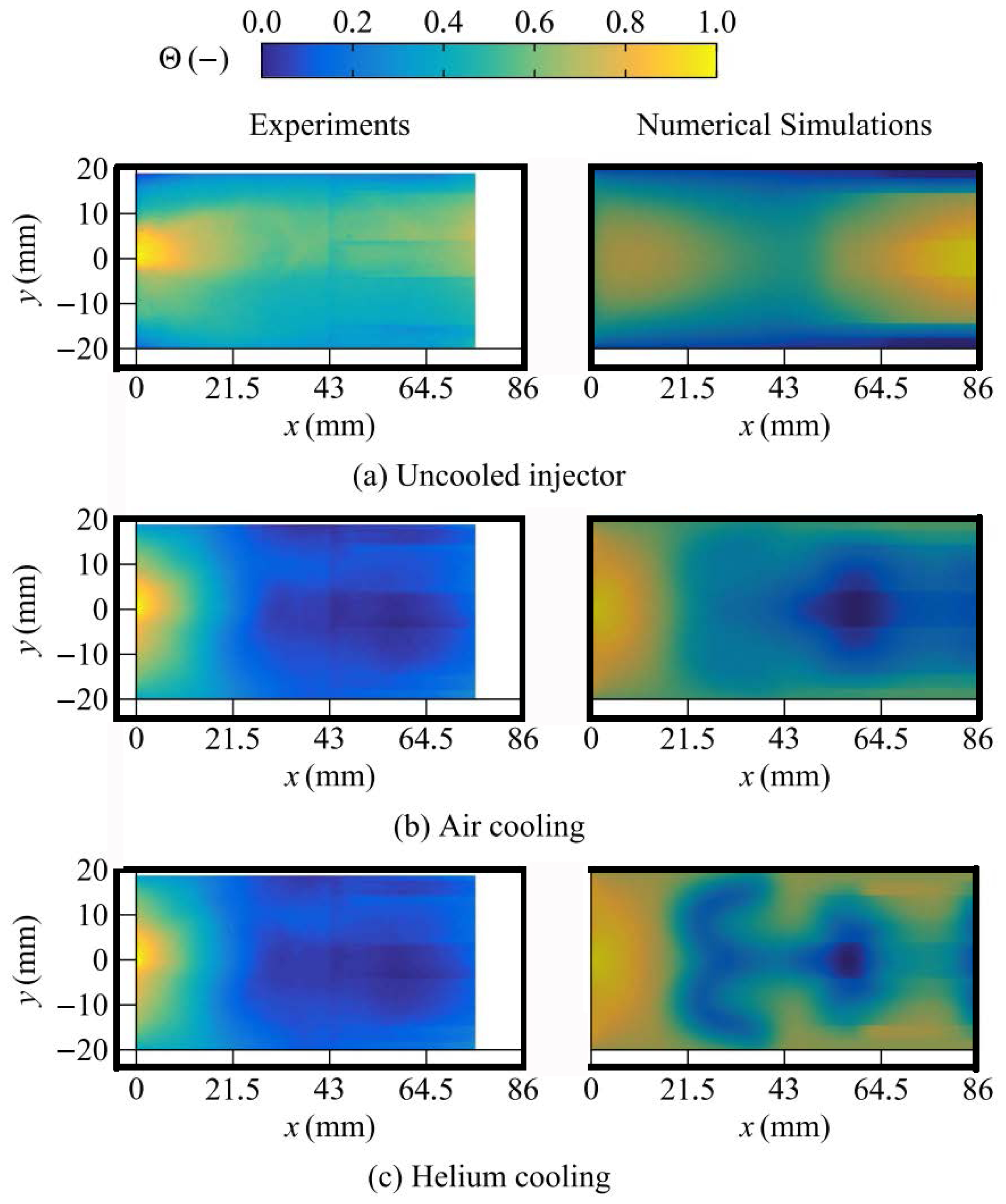
Fan et al. [43] studied the relationship between air film cooling effect and the film spray angle, and between mass flux of the coolant and the spray temperature in the combustion chamber of propulsion systems. The conclusions show that a relatively small spray angle can achieve a comparatively good air film cooling effect. The increased mass flux of the coolant can improve the air film cooling effect, whereas when the mass flux exceeds 3% of the main fluid mass, the cooling effect will no longer be obvious. Coolant temperature has a relatively complicated impact on the air film cooling effect, but in general, if the coolant temperature rises, the air film cooling effect will be weakened. In a study by Keller [44], the effects cooling gas properties on air film cooling in supersonic flow environments was explored, and research findings about numerical simulation of supersonic boundary laminar flow were proposed. As for the effect of the cooling gas properties on the gas film, the gaseous-diffusion coefficient was found to have no effect on the cooling performance, yet the cooling effect can be improved by low thermal conductivity, low viscosity, high Prandtl number, low molar mass, and low density of the cooling gas. Among the gases studied, helium and hydrogen have the highest cooling efficiency, which are three and six times that of air respectively (see Figure 7). In terms of numerical simulation, it was found that turbulent flow rather than laminar flow will speed up the acceleration of the cooling film, resulting in a decline in the cooling effect of the air film. Nevertheless, the flow rate in Keller’s study was only about 2.6 Mach. To be applied to air film cooling of propulsion systems, calculation and experimental analysis with high Mach numbers still needs to be carried out.
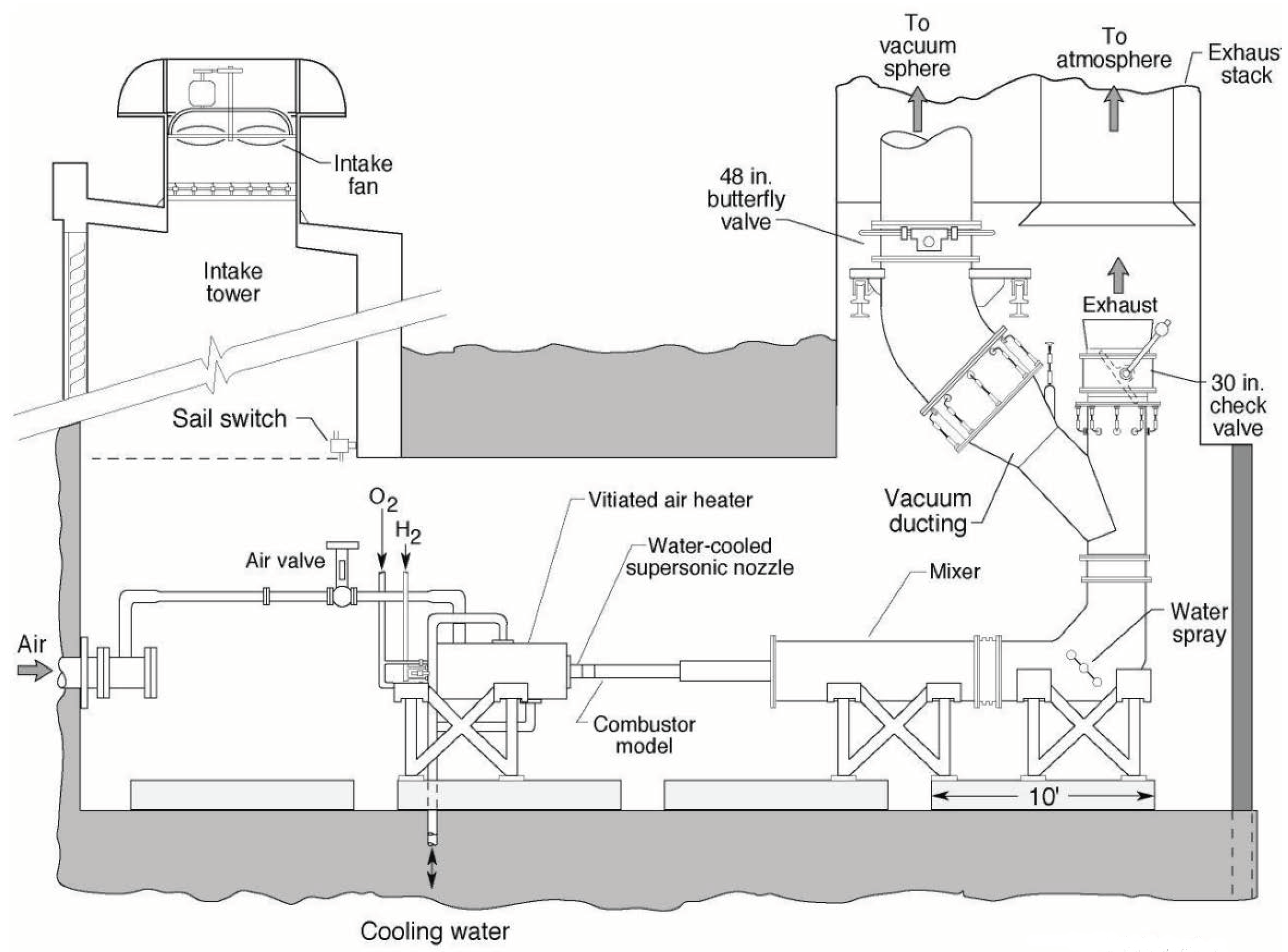
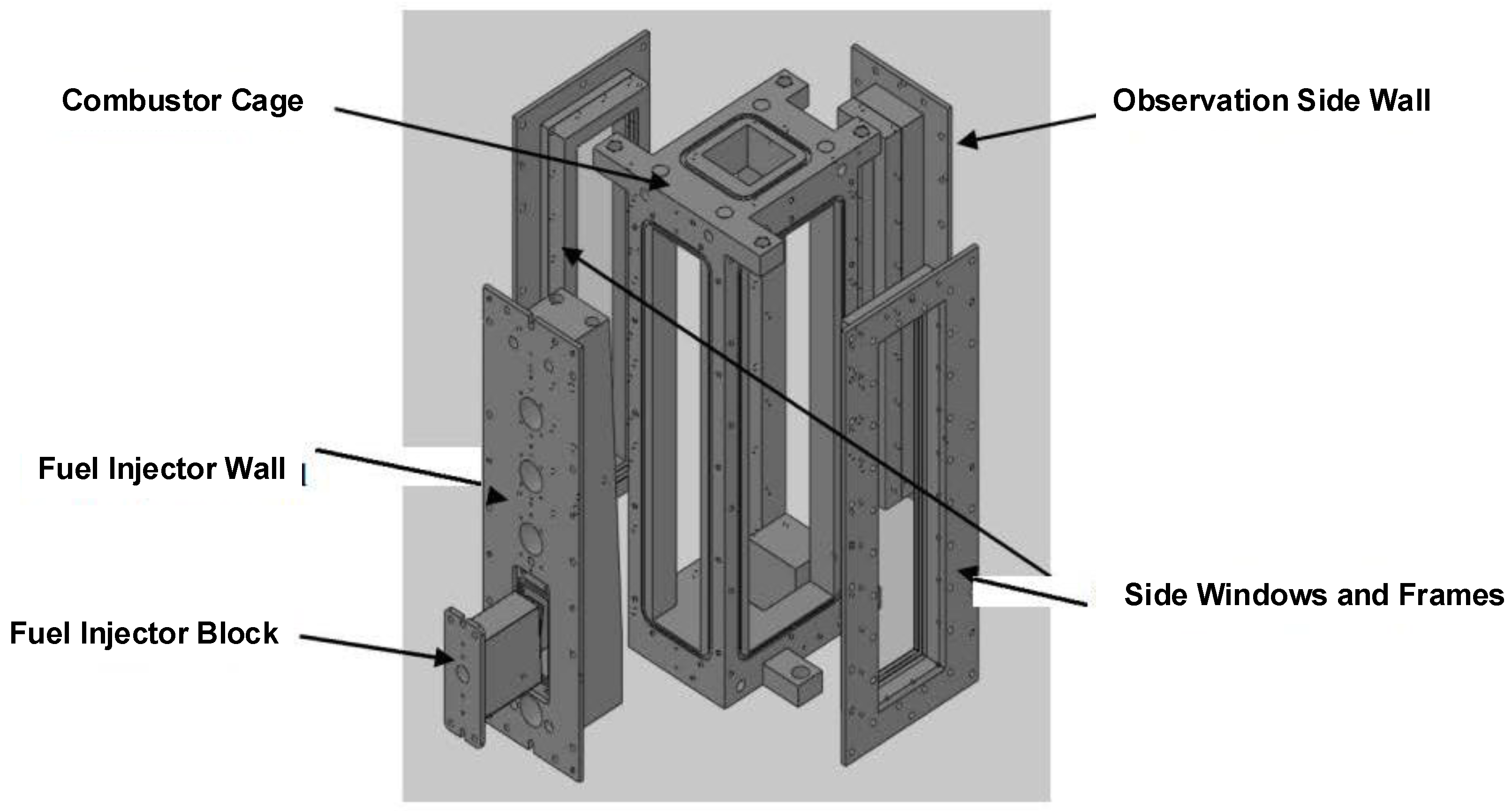
In addition to air film cooling and regenerative cooling, sweat cooling is also an important method of active thermal protection for propulsion systems, the principle of which is mainly that the coolant is exuded from the surface by porous materials to provide thermal protection to the heated parts. Gulli et al. [45] compared the sweat cooling methods of two structures, i.e., flat plate and front edge of bluff body, through numerical analysis (see Figure 8) represents the a flat plate and a two dimensional (2-D) body with blunt leading edge, respectively and concluded that the serrated wall velocity distribution can save about 37% coolant compared with the flat plate structure under the same cooling conditions. In addition, front edge of bluff body has a better sweat cooling effect than flat plate, with a cooling efficiency about 8% higher than that of flat plate. Brune et al. studied the effect of variable sweat cooling in advection and turbulent flow in hypersonic flow environments [46]. According to the numerical analysis, for common laminar and turbulent flows, variable transpiration cooling is more effective than uniform transpiration cooling, and the numerical analysis also verified that transpiration in turbulent boundary layer is less efficient than laminar flow. Moreover, as for the same amount of coolant mass used for the thermal analysis of the bluff bodies, the pressure drop of variable sweat cooling occurring on the thickness of the turbulent material in the slope region is slightly lower than that occurring on the laminar flow. Such numerical simulations of sweat cooling mainly focus on the cooling efficiency of sweat cooling in different flow environments and when different materials are used, which can provide references for the design of sweat cooling for active thermal protection systems, e.g., the combustion chamber and air inlet, of propulsion systems. The DLR made a preliminary experimental verification of the direct applicability of sweat cooling to ramjets [47], with the experimental verification diagram and the physical map of the experimental apparatus shown in Figure 9, the test bench consists of a hydrogen and orxygen air vitiator(A, B, C in Figure 9a,b. This experimental apparatus can verify the applicability of sweat cooling systems under the thermal and mechanical loads of ramjets. The experiment confirmed the sweat cooling system to be a potential solution to high wall temperature and mechanical load of ramjets.
For sharp components in hypersonic propulsion systems, Hanquist proposed a new potential cooling method, electric transpiration cooling (ETC), and conducted a series of studies on modeling and computational fluid dynamics (CFD) calculations [48,49,50,51]. However, since the ETC sweat cooling material is still being researched and developed in the current stage, most studies on ETC cooling mainly focus on analyzing the cooling principle and optimizing the calculation model. Nevertheless, it is foreseeable that with the further development of ETC materials and the realization of in-depth studies that include relevant experiments to verify the reliability of ETC materials, ETC will become a potential leading-edge active thermal protection technology in the future for sharp components that have the harshest requirements on the thermal environment of propulsion systems.

2.4. Latest Research Progress of Thermal Barrier Coating

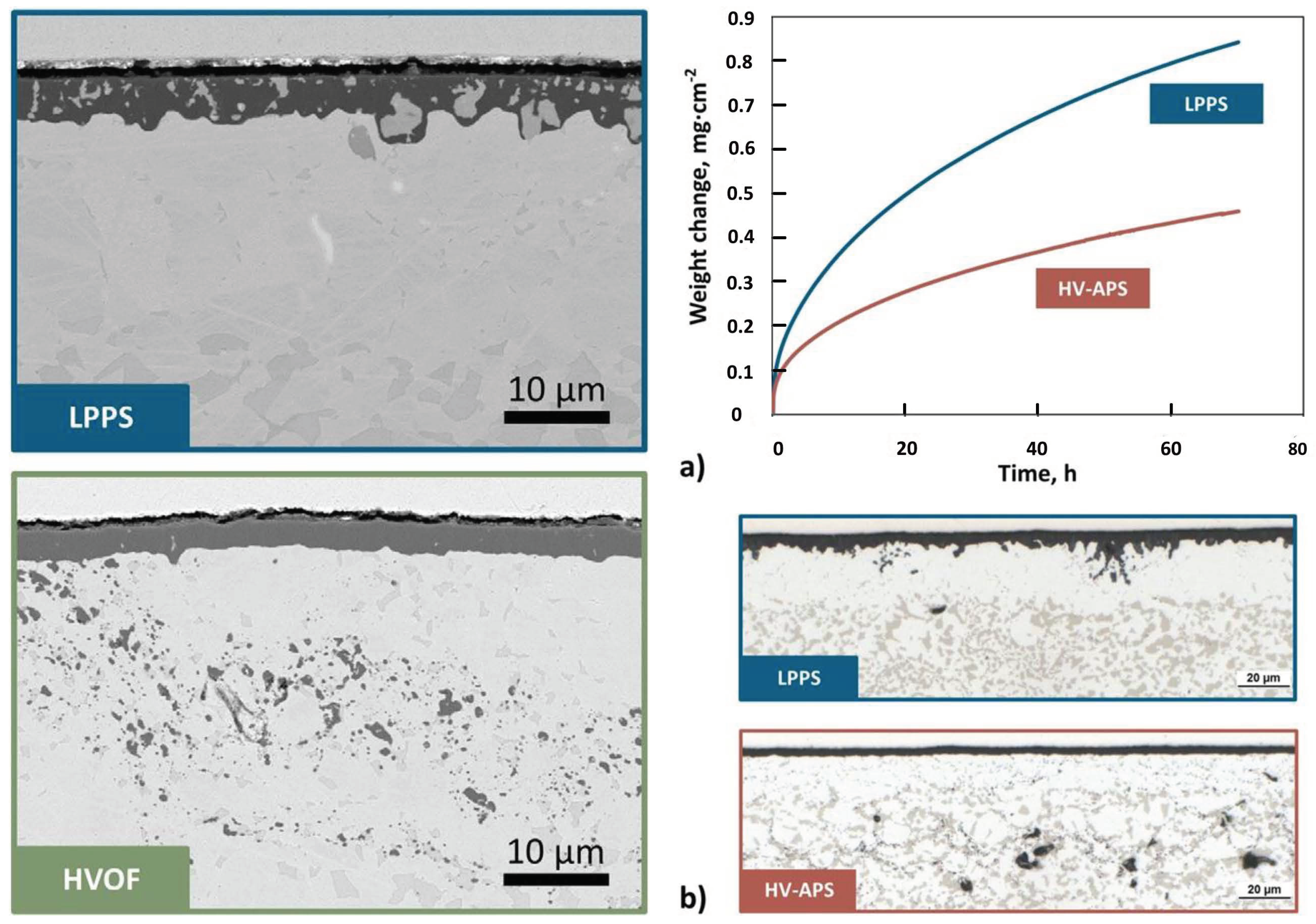
In current studies on the adhesive layer MCrAlY, Mauer et al. [52] proposed to improve the performance of the adhesive layer by optimizing its processing conditions and raw material properties, stating that a good adhesive layer should take into account low oxidation as well as the structural density. In this study, the particle diagnostics method was used to investigate the effect of processing conditions and raw material properties on the performance of the adhesive layer under high-speed APS conditions. The results show that the oxygen/fuel ratio, spray distance, and particle size distribution are the important parameters to prepare an ideal adhesive layer. Besides, in this experiment, the oxidation of the three spraying processes, i.e., hyper velocity air plasma spray (HV-APS) [53], low pressure plasma spray (LPPS) [54], and hyper velocity oxygenated fuel spray (HVOF) [55], were compared horizontally in a high temperature environment, Figure 10a shows a comparison of the oxide scales formed on 0.6 mm thick freestanding specimens of coating. Using Amdry 9954 powder manufactured by Oerlikon Metco, Zurich, Switzerland based on the process of LPPS and HVOF after 72 h isothermal oxidation at 1100 C. In the latter coating, the relatively high oxygen content has as a result, that most of the reactive element yttrium is tied up in form of oxide pegs in the inner part of the surface scale, seen in case of the LPPS coatings, is not observed for the HVOF specimen. It will be shown below that the same is the case for the HV-APS coatings. The isothermal oxidation tests at 1100 C in synthetic air for 72 h revealed that a significantly lower oxidation rate for the freestanding samples of the HV-APS coating as compared to the LPPS coating, as shown in Figure 10b. For the HV-APS coatings, the depletion of the alumimum-rich beta phase is less advanced and TGO is thinner and more homogeneous. In the case of the HV-APS sample, it was observed that Y [56] incorporated less in the oxide skin, resulting in a better coating effect. However, this study failed to further explore the formation mechanism of microstructure and influences of the distribution of specific oxides on the oxidation behavior.
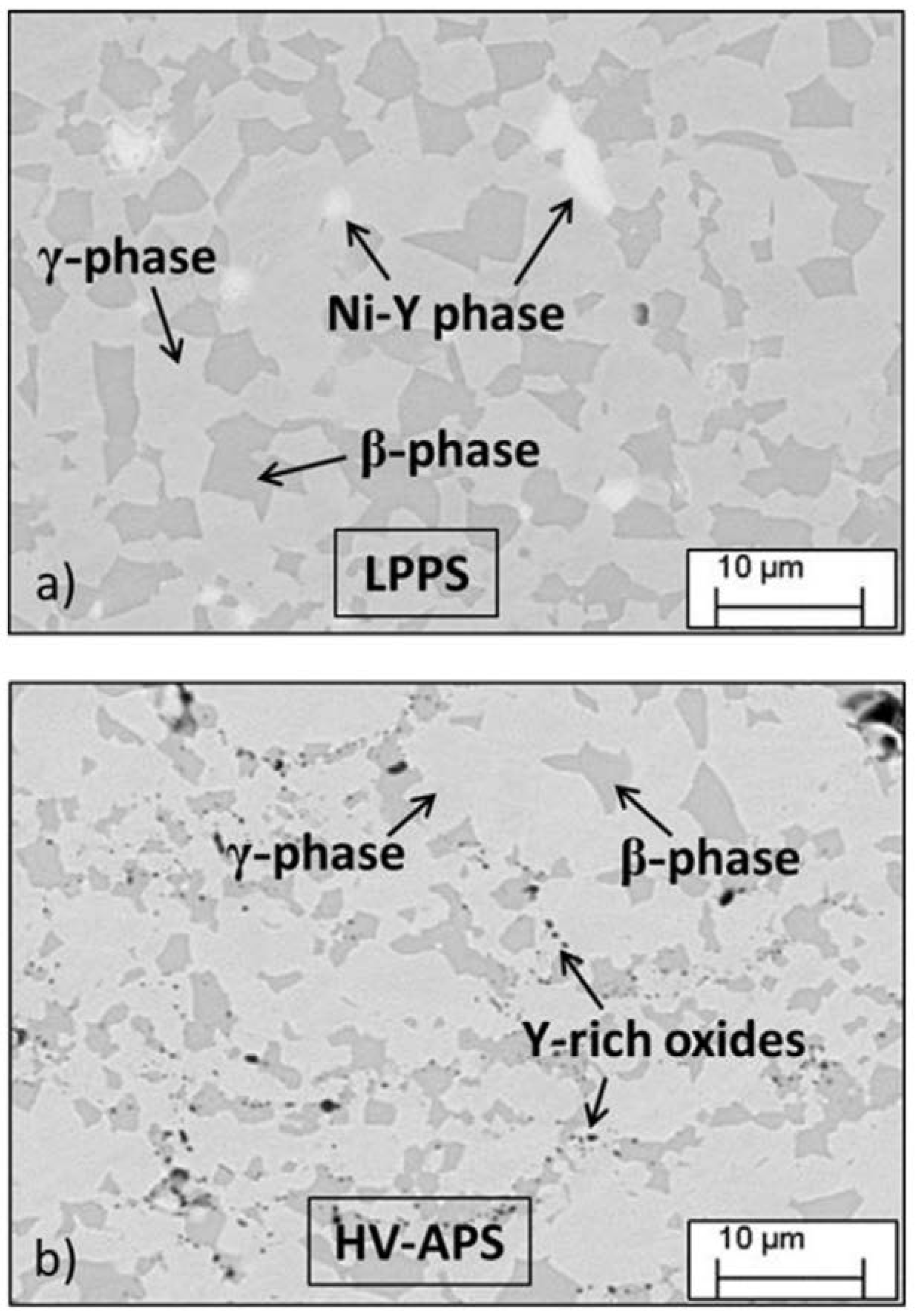
In a study by Hejrani [57], an isothermal experiment was carried out to analyze the microstructure of the oxides (see Figure 11), pointing out that the HV-APS material has excellent adhesion because the specific yt-trium distribution in the form of precipitates of fine oxides in HV-APS material prevents the formation of harmful Y-rich oxides and promotes the formation of slowly growing protective alumina scale. The research results provide a powerful theoretical basis for HV-APS as a feasible material to be used in the preparation of adhesive layers in the future. In addition, by analyzing the arithmetical mean roughness (Ra) of adhesive layer with specific parameters, Nowak et al. [58] proposed to apply the “flash coating” [59] prepared by the APS method to the substrate coating prepared by the HVOF method, which can greatly extend the life of the APS thermal barrier coating system with an HVOF coating (see Figure 12).
In general, there are few researches on MCrAlY and its modification. The latest research progress on adhesive layer mainly focuses on the preparation method of MCrAlY and the mechanism of its service life. Cracking, oxidation, and other microscopic damage mechanisms of MCrAlY will probably be one of the research focuses on the adhesive layer in the future, so as to guide the preparation of the adhesive layer of thermal barrier coating with a longer service life more effectively based on microscopic theories.
In terms of preparation of the surface layer of thermal barrier coating, NASA combined both YSZ modification and rare-earth zirconate replacement [60] to solve the insufficient thermal barrier of 7YSZ applied to hypersonic aircrafts by mixing rare-earth metals (Yb and Gd) with yttria to stabilize zirconia (t’Low-k) and Gd 2 Zr 2 O 7 pyrochlore (GZO). NASA also developed a novel multi-layer structure consisting of nanolayer and thick-layer microstructures. However, it has been experimentally shown that although GZO coatings have relatively good performance in thermal conductivity and sintering resistance, its corrosivity is one order of magnitude stronger than that of the classical YSZ (see Figure 13), which seriously limits the current application of GZO coatings. The thermal conductivity of this multi-layer structure is significantly reduced compared with that of YSZ, which plays a catalytic role in solving the thermal protection problem of hot components, and future researches on multi-layer structures will focus on exploring the stability and interaction of GZO and YSZ/Low-k coatings. Cracks at the black arrows in Figure 13c are significantly deeper than those of Figure 13a,b.
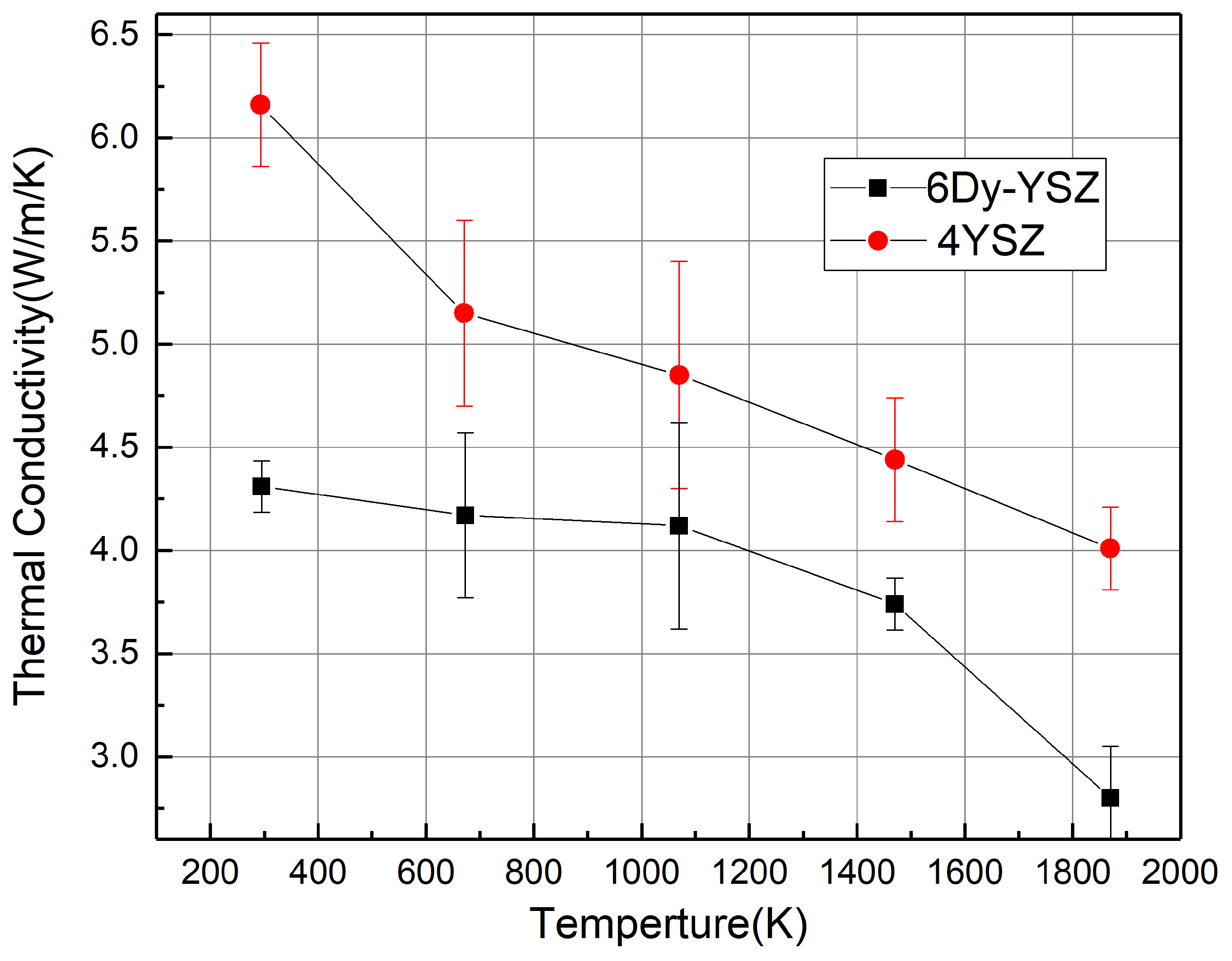
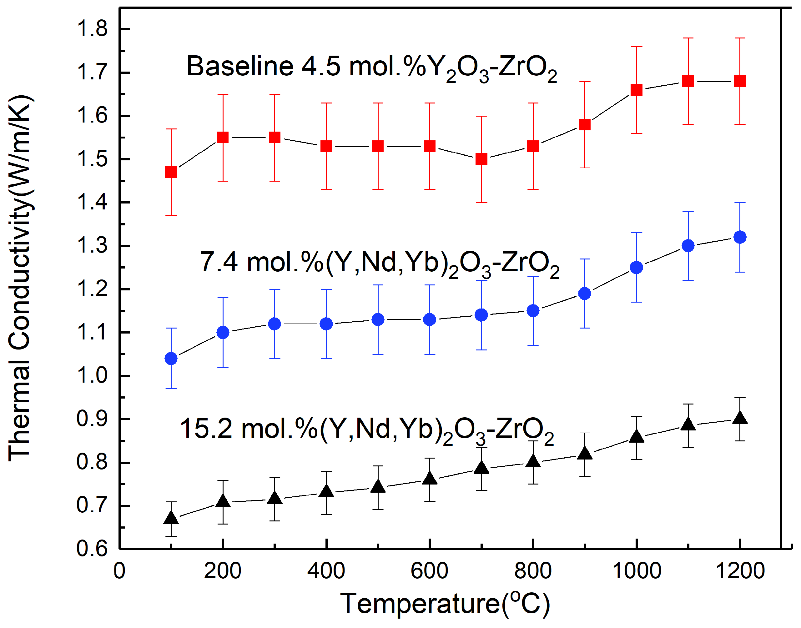
Qu and Choy [61] prepared the tetragonal crystal Dy 0.06 Y 0.072 Zr 0.868 O 1.93 using the sol-gel method [62], and then simulated and studied the relationship between the chemical components and thermodynamic properties of tetragonal crystal through experimentation and molecular dynamics (MD) [63]. The crystal structure was theoretically studied and its intrinsic thermal conductivity was calculated through MD simulation, the results of which show that the new structure can effectively reduce the thermal conductivity compared to the conventional YSZ structure, as shown in Figure 14. Gong et al. [64] investigated the effect of rare earth doping on the structure, microstructure, and thermal conductivity of crystal by spraying rare earth doped with YSZ using suspended plasma spray (SPS) technology [65]. The results of the thermal conductivity measurements show that as the Nd 2 O 3 /Yb 2 O 3 concentration increases, the thermal conductivity decreases (see Figure 15). In addition, many modifications, such as CeO 2 , Sc 2 O 3 , and ZrO 2 -Y 2 O 3 -Nd 2 O 3 (Gd 2 O 3 , Sm 2 O 3 )-Yb 2 O 3 (Sc 2 O 3 ), have also been studied, most of which can effectively reduce the thermal conductivity of thermal barrier coating materials.
In the current stage, improvements have been made in aspects such as modification of the multicomponent oxides of YSZ and the substitution of YSZ with rare earth zirconate in the outer surface of thermal barrier coating. However, current researches mainly focus on how to reduce the thermal conductivity of the material, whereas later researches may concentrate on experimental and theoretical analyses of oxidation and stability of thermal barrier coatings, and how the microscopic lattice and defect clusters affect the thermal conductivity, stability, and toughness of thermal barrier coatings, in the hope of finding materials with excellent performance to be used in propulsion systems of hypersonic aircrafts.
APS was commonly used in the past to prepare thermal barrier coatings because it is easier to prepare thermal barrier coatings with APS technology and the thermal conductivity of the coating is relatively low [66]. Nevertheless, the unavoidable disadvantage of the APS technology is that the layered structure coatings it produces usually contain a large amount of lateral micro-cracks that are likely to expand due to the thermal stress in high temperature environments, which can cause the coatings to fall off and prematurely fail [67]. Therefore, for propulsion systems of hypersonic aircrafts, it is of great significance to develop thermal barrier coatings with a small thermal conductivity and a strong anti-seismic ability. As a relatively new technology that uses thermal spray to prepare thermal barrier coatings with excellent performance, the SPS technology uses nano- and micron-sized particles of colloidal suspension as a coating material to achieve good liquidity. In a study by Sokołowski [68], the microstructure and thermal properties of YCSZ coatings obtained by SPS were investigated. Carpio [69] discussed the microstructure and indentation mechanical properties of YSZ nanostructured coatings obtained by SPS. Bernard et al. [70] sprayed the YSZ columnar coating with SPS, and the experimental results show that the columnar structure produced may be able to meet the requirements of the next generation of turbine engine. Moreover, the study also shows that coatings produced by the SPS technology can be strongly stuck to the components and will not fall off easily (as shown in Figure 16). With this feature, the SPS technology has a better prospect to be applied in spraying high-pressure parts of propulsion systems, e.g., the turbine engine blade. Apart from plasma spray, there are also studies and experiments on the application of physical vapor deposition and laser cladding technology [71] to prepare thermal barrier coatings used in propulsion systems. However, due to the complex preparation process, high preparation cost, and poor repeatability, these technologies are not mature enough as compared to the APS technology. In addition, since most studies only focus on how to reduce the thermal conductivity, rather than further probing into the failure mechanism or involving other properties of thermal barrier coating, the development of spray technologies for thermal barrier coating may still concentrate on the optimization of SPS technology for a period of time in the future.

3. Thermal Management of Propulsion Systems

3.1. Overview

The ultimate goal of aircraft thermal management systems is to maintain the temperature of sensors, components, instruments, spacecraft, or space equipment within a required range, regardless of changes in the thermal load caused by the external environment or operation [72]. For propulsion systems of hypersonic aircrafts, thermal management mainly aims to ensure that the working components of the propulsion system are maintained at the allowable temperature, and on the basis of assuring temperature safety, the thermal analysis and optimization design of the flow path system can be carried out to improve the performance of the engine and collect waste heat so as to improve fuel energy utilization and therefore reduce the fuel’s quality penalty on aircrafts. Since the design of thermal management of propulsion systems is of great importance to hypersonic aircrafts, and its research subsystems cover a wider range as compared to that of thermal protection systems and thermal barrier coatings, there are relatively few studies in this regard [73].
Therefore, in this study, the latest developments of each subsystem of propulsion system thermal management were emphatically introduced. In this section, the research progress of thermal management in relevant modules will be introduced from the perspectives of three sub-systems, namely the low-temperature system (Section 3.2), thermal control system (Section 3.3), and thermal coupling system (Section 3.4).

3.2. Low-Temperature Systems

Due to the requirements of hypersonic aircrafts, ordinary fuel cannot meet the high specific impulse required by hypersonic aircrafts when the Mach number is relatively high and low-temperature fuel such as liquid hydrogen is needed as the propulsion fuel for ramjets [74]. Low-temperature fuel storage, fuel transfer, heat transfer, and the selection of fuel are all sub-areas designed in the low-temperature systems. The purpose of the low-temperature system is to maximize fuel ignition and recycle efficiency while ensuring system safety so as to increase fuel utilization [75].
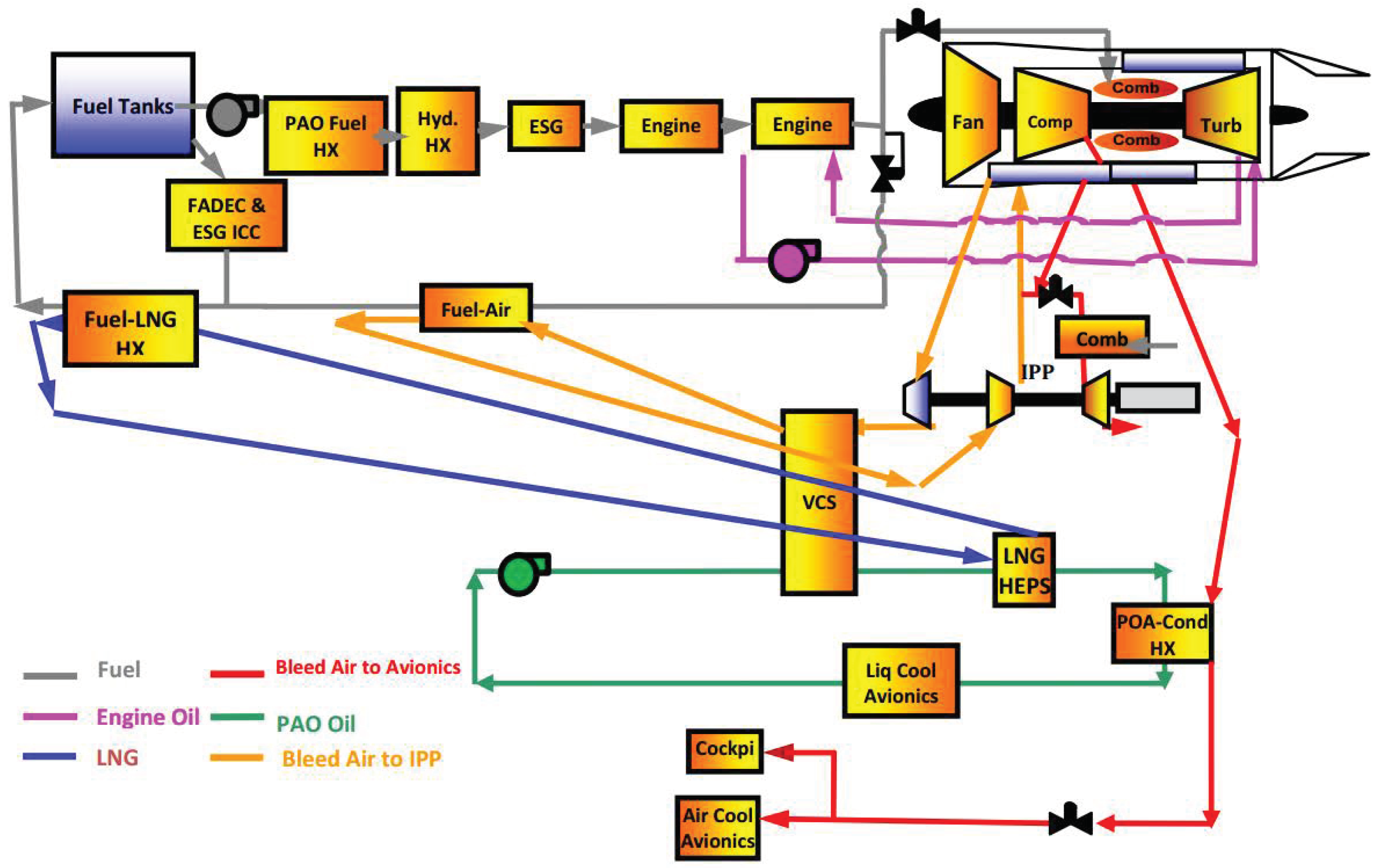
In terms of fuel selection, liquid hydrogen is used as the fuel in most researches on low-temperature systems, mainly because of its high thrust-weight ratio [76] (see Table 2). However, its shortcomings are also obvious. First, the density of liquid hydrogen is very low (70 kg/m 3 ), which leads to large volume waste for hypersonic aircrafts. Second, the boiling point of liquid hydrogen is about −252 C, making both the storage and ignition difficult to some extent. Roberts et al. [77,78,79] proposed to replace liquid hydrogen with liquefied natural gas (LNG), designed oiling channels of the entire propulsion system based on LNG, as shown in Figure 17, and pointed out that LNG can also meet the thrust-weight requirements of hypersonic aircrafts under certain conditions per the dynamic tip to tail (T2T) model for quantifying the energy conversion, and the boiling point and density of LNG are higher than that of liquid hydrogen. If LNG can be used as a propellant of hypersonic aircrafts under high Mach numbers in the future, the storage cost and difficulty in designing the oiling channels of low-temperature systems will be remarkably reduced.
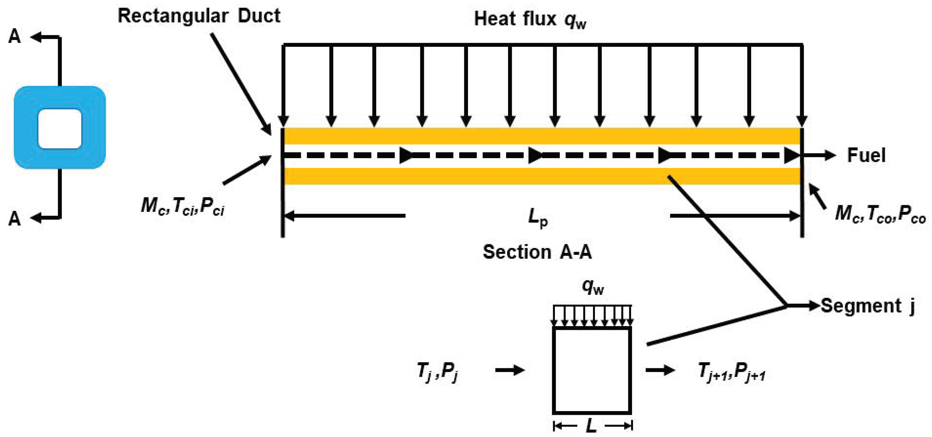
For the modeling of fuel delivery in low-temperature systems, Qin [80] proposed a one-dimensional model of the fluid and heat transfer processes in the single-channel cooling process of an endothermic hydrocarbon-cooled scramjet established based on the thermal reaction equation. Figure 18 shows the calculation model of the single cooling channel of the proposed ramjet and Figure 19 is a flow chart of the experimental verification.
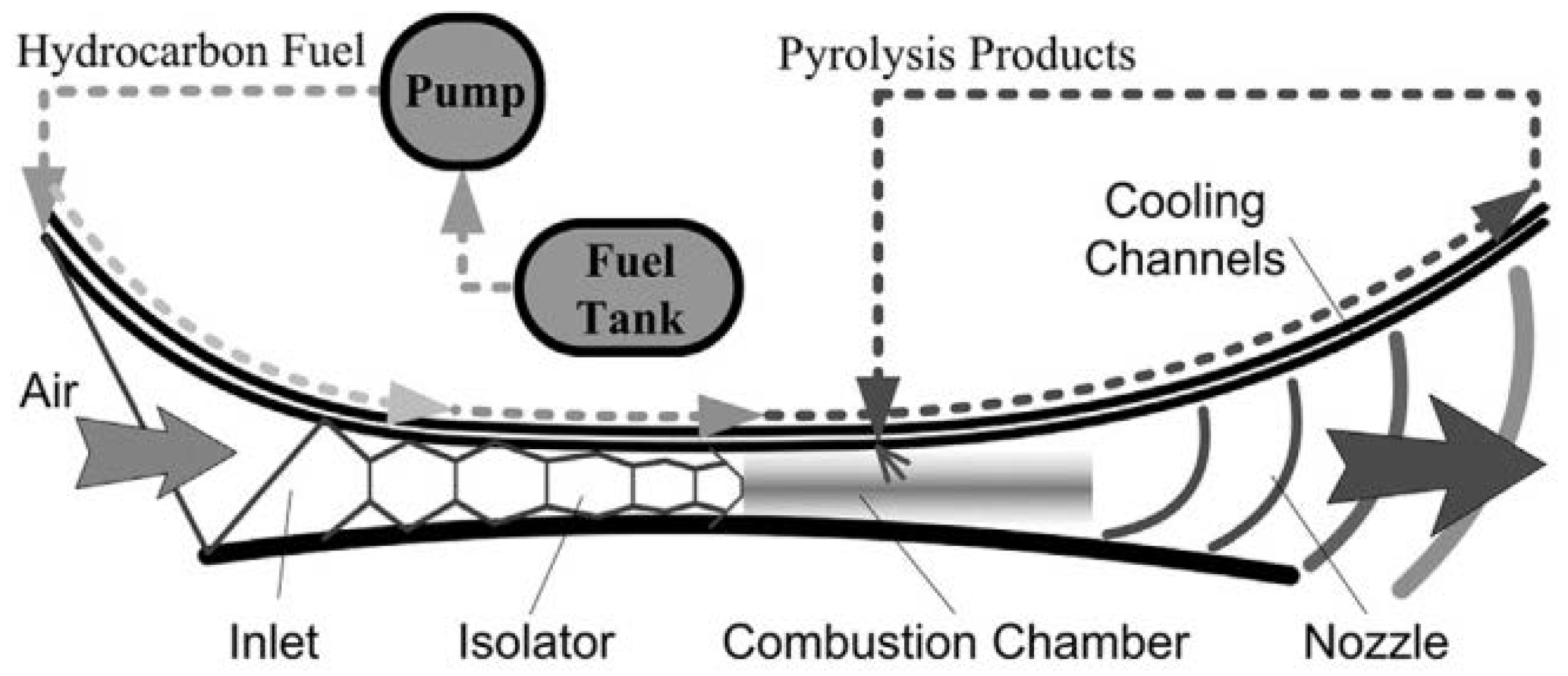
Besides noting the effect of temperature, flow field rate, and pressure on heat sink of the fuel, the model proposed that controlling the flow pressure can be used as a local management method, which is a relatively innovative idea in thermal management. Moreover, the working process of regenerative cooling scramjets was analyzed from the perspective of energy cascade [81] (see Figure 20). In fact, the conceptual model of a single cooling channel is a circulating cooling method in active thermal protection systems of combined propulsion, which reduces the temperature of the working wall via heat transfer in the cooling channel at relatively low temperature.
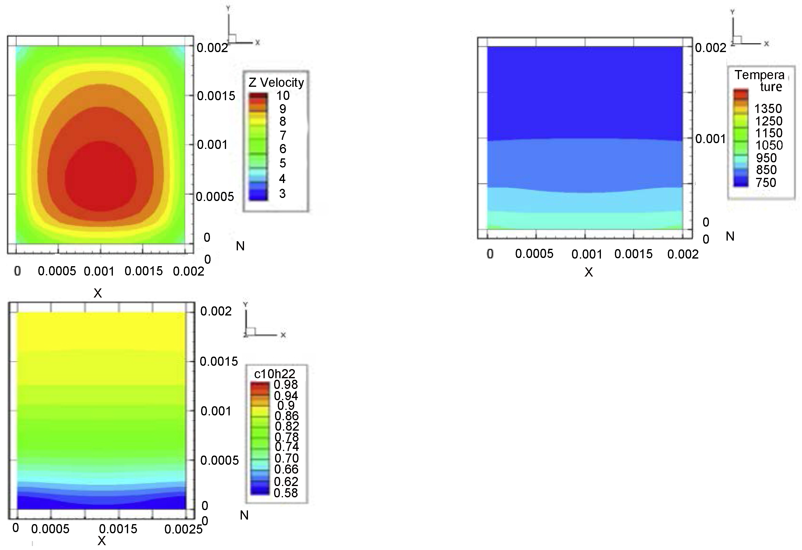
Zhang et al. [82] studied fuel thermal management focusing on the chemical cycle of fuel. Experimental results of the thermal cracking of n-decane show that the mechanism of regenerative cooling improves the performance of scramjet through energy cascade. additionally, a three-dimensional model was used to analyze the outlet flow rate, temperature, and chemical reaction of n-decane distribution (see Figure 21). The analysis demonstrates that the fuel pressure can affect the chemical cycle and improve the heat transfer performance of the fuel. Moreover, the simulation results of the three-dimensional model show that the velocity and temperature of cross-sectional fuel are not uniform, which has adverse effects on both the physical and chemical cycles. When the fuel rate remains constant, passing through channels with a relatively small width can improve the heat sink conversion efficiency of the fuel and lead to a better chemical cycle effect. Based on this, in a study by Bao [83], a numerical analysis was conducted on the flow-cracked hydrocarbon fuel in the cooling channel, pointing out the necessity of studying the factors that affect the heterogeneity of the fuel heat sink. Providing some references for the simulation modeling and energy optimization design of cooling channels for future propulsion systems, this series of studies possesses the potential to further exploration on how to improve energy conversion and ignition efficiency through optimizing physical parameters of thermal management.
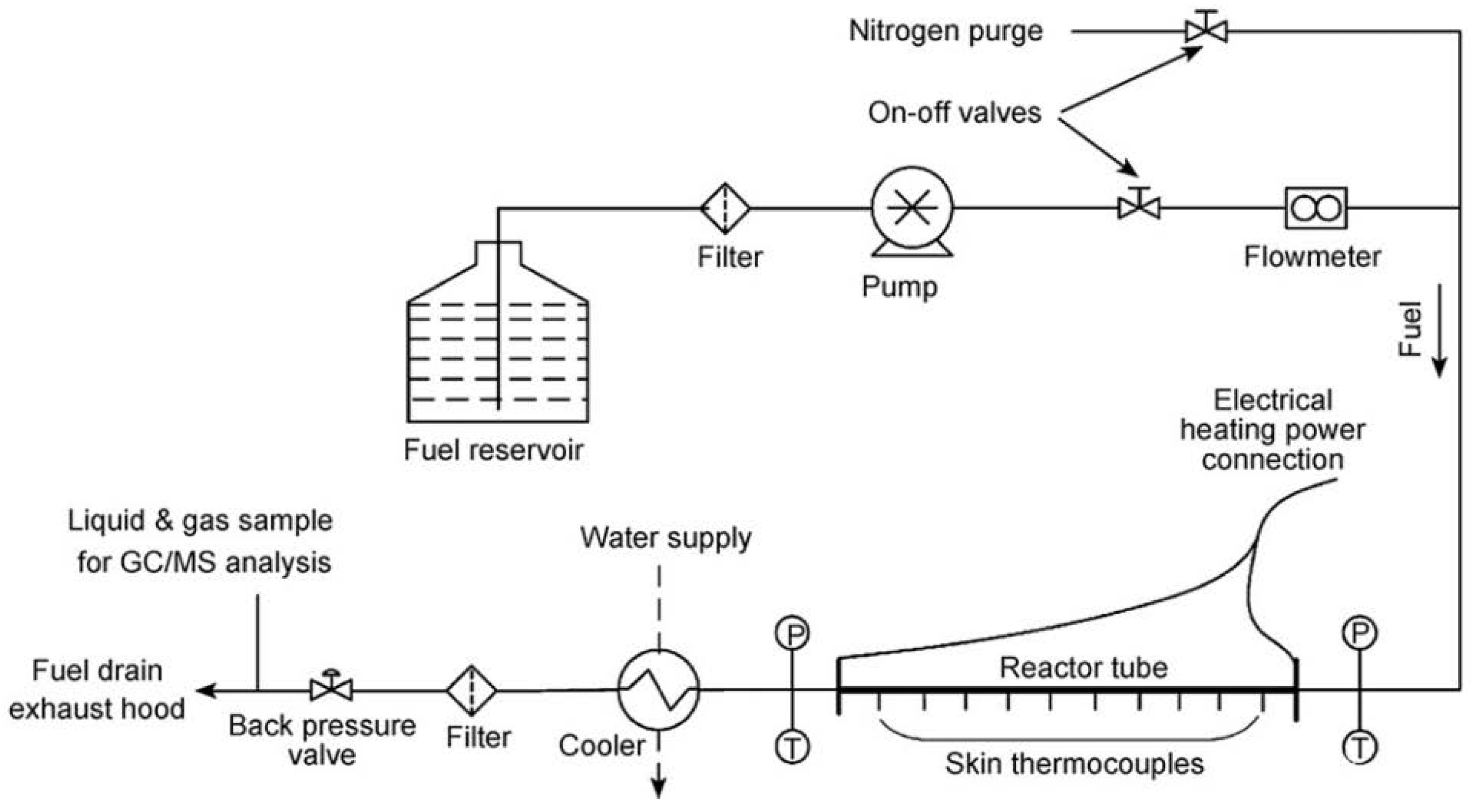
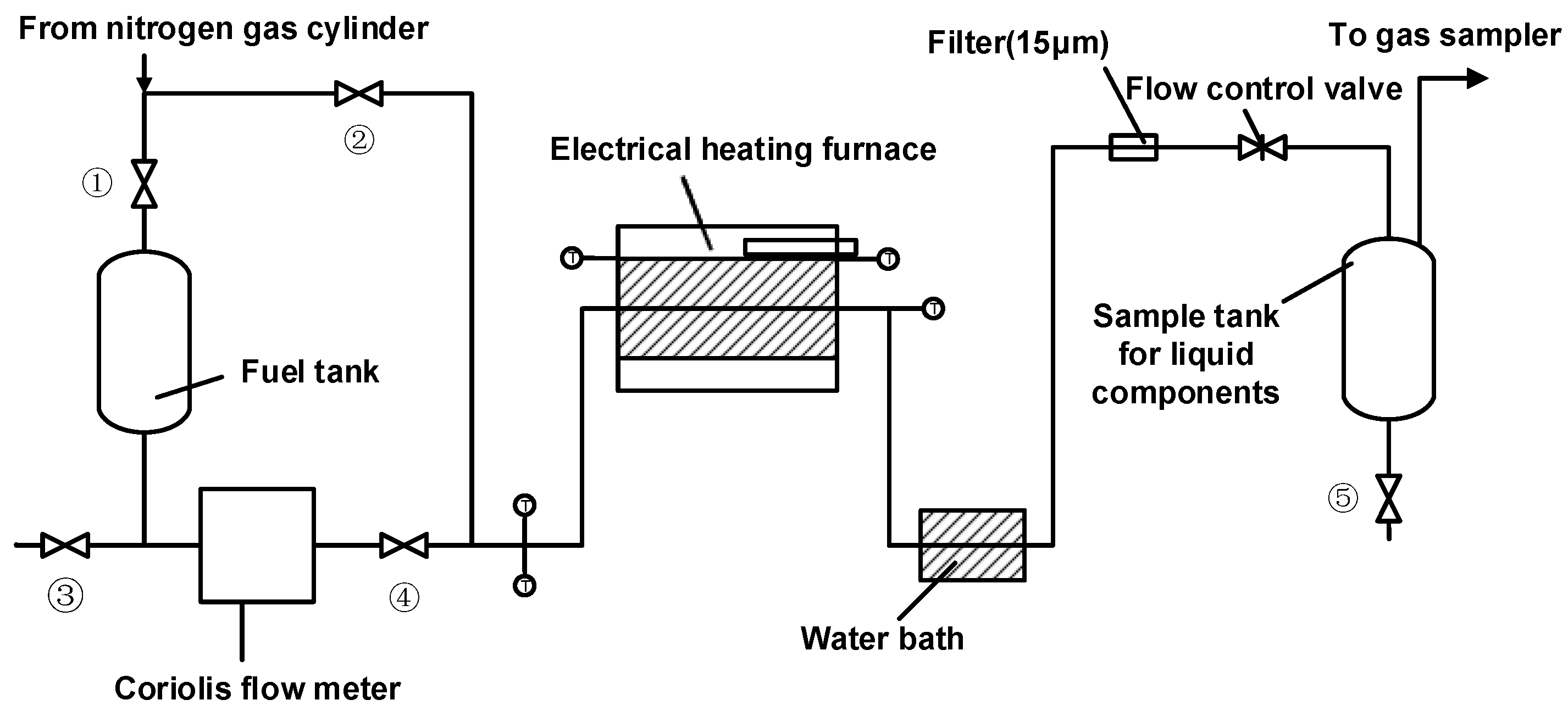
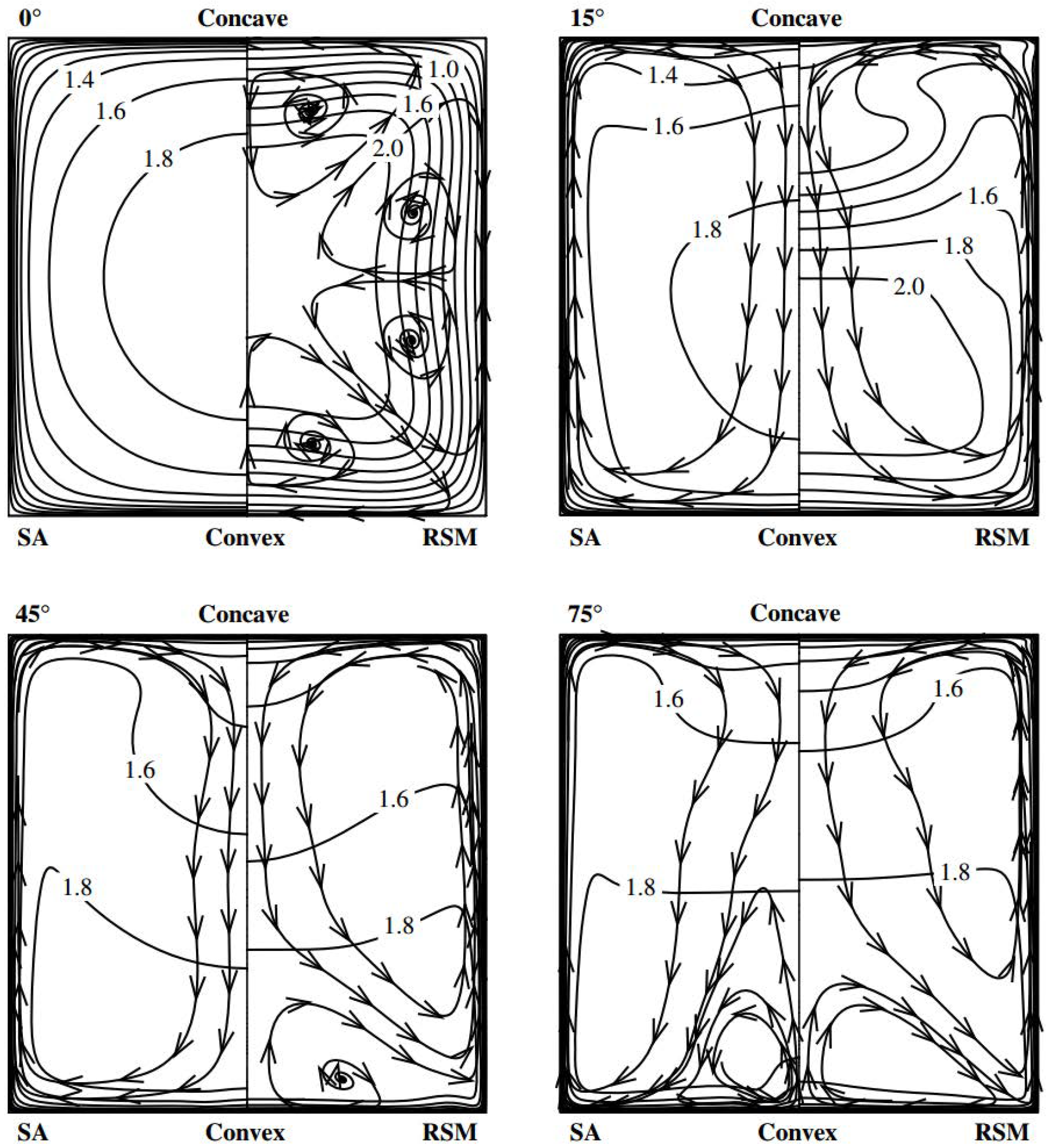
Nakaya et al. [84] investigated how the pyrolysis components of n-dodecane affect the combustion behavior of the fuel with the experimental setup shown in Figure 22. With universal applicability to other hydrocarbon fuels, this method has certain value in system fuel selection. Liang et al. [85] studied the coupled heat transfer of scramjet in a curved cooling channel and explored the influence of secondary motion and wall thermal conductivity on heat transfer. The flow fields obtained from the Spalart-Allmaras model [86] and the Reynolds stress model [87] were compared (see Figure 23), and the numerical results show that the Spalart-Allmaras model is less computationally intensive than the Reynolds stress model and thereby the result gained by the Spalart-Allmaras model is more reasonable. In addition, the flow and heat transfer in the cooling channel are important reference values for the design of the active cooling scramjet. The experimental results show that materials with a higher thermal conductivity can make the heat flux and temperature of the flow field distribute more uniformly in the cooling channel.
In a study by Liu [88], the thermal structure of the cooling front of the cooling channel of an endothermic hydrocarbon-cooled scramjet was analyzed, the thermal/stress distribution of the aircraft under steady flight conditions was classified by finite element software (see Figure 24), and the feasibility of the materials of C-103/Na and T-111/Li was demonstrated. Jing et al. [89] proposed a regenerative cooling channel designed by various non-uniform patterns, and numerically investigated the conjugate flow and heat transfer behavior between the coolant and solid combustion chamber. In a study by Taddeo [90], the effect of fuel cooling on the combustion chamber was explored, the heat transfer efficiency of the cooling system was evaluated, and the hysteresis effect caused by heat transfer kinetics was demonstrated as well. Besides, the relationship between fuel cooling carbon deposition [91] and fuel cooling efficiency was also investigated to some extent [92], and a method to detect carbon deposition was proposed and verified.
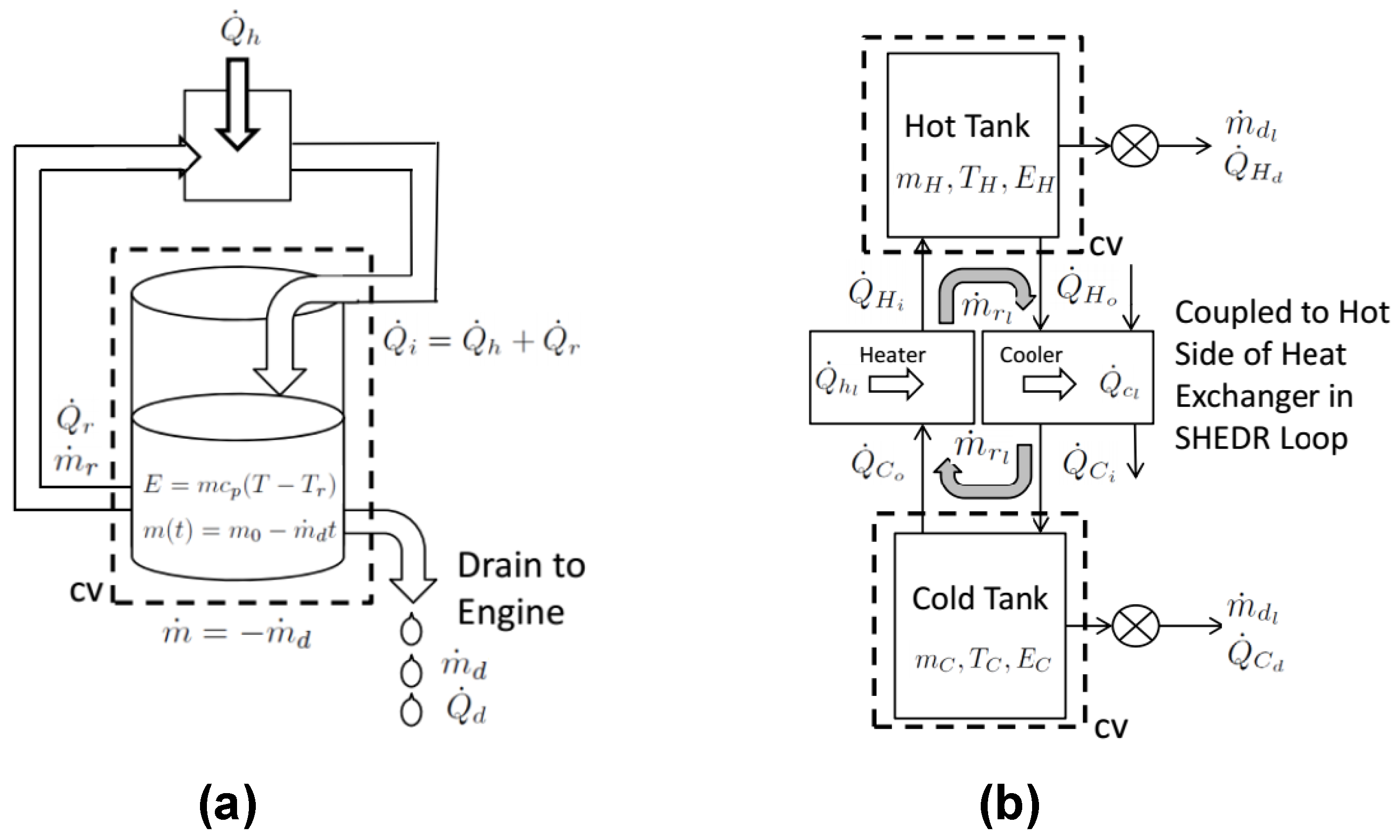
As shown in Figure 25, Split heat exchange-drain-recirculation (SHEDR) cycle is a classic model from the preheating of fuel from a cold storage tank to an engine [93]. There are many researches on modeling and simulation of this cycle, which will be introduced in detail when the simulation and coupling subsystems are involved in the thermal coupling system in Section 3.4.
It can be seen that current researches on cooling systems mainly focus on one-dimensional modeling of heat conduction, with improving the circulating cooling efficiency as the main research direction. However, there are few studies on the stability of liquid hydrogen fuel used in long flights of hypersonic aircrafts and the evaporation of liquid hydrogen fuel during storage. It is foreseeable that more attention will inevitably be paid to the stability of liquid fuels such as liquid hydrogen in future researches. Moreover, with a relatively high density and boiling point, LNG has the potential to be applied to hypersonic aircrafts. In the future, further explorations will be carried out on the feasibility of applying LNG to propulsion systems in the hypersonic mode.

3.3. Thermal Control Systems

The main purpose of thermal control systems in hypersonic vehicles is to control the temperature of various parts of the propulsion systems and to ensure that the temperature of each component is within a safe range of allowable temperature [94]. Studies based on thermal control systems mainly involve the design of channels for fuel oil and lubricating oil, as well as heat conduction among various parts of the propulsion system and relevant thermo-mechanical analyses.
The Langley Research Center of NASA simulated and measured the thermal radiation of ramjets at high Mach numbers [95]. Thermal radiation is a potential factor influencing the calculation of the flow field and wall temperature in the combustion chamber of a ramjet, as shown in Figure 26 [96], yet there are not sufficient experimental verifications of simulation approaches for thermal radiation. In this study, a ray tracing method was proposed to simulate thermal radiation in the flow field, which was verified to some extent. It was also pointed out that the direction of further studies on thermal radiation is mainly based on the introduction of LES simulation [97], turbulent flow fluctuations, and changes in simulation results caused by change of the experimental time.
In a study by Chen et al. [98], the effect of heat conduction and radiation on the heating of bluff bodies was explored, and the aerodynamic heating of bluff bodies in hypersonic fluids was simulated based on coupled computational fluid dynamics and computational thermodynamics. The isothermal boundary conditions of the constant wall temperature were studied, with the isothermal boundary conditions of structural heat conduction and radiation taken into consideration. The calculation results show that when the wall temperature remains constant, the maximum wall heat flux density is almost 20 times that of the structural heat conduction considered. Thermal radiation also affects the calculated wall heat flux and wall temperature, yet its effect is not significant compared to heat conduction. It was also found that the k- ε turbulence model [99] used in the simulation does not have a significant effect on the results near the stagnation point (as shown in Figure 27).
In a study conducted by Larsson [100], a method based on new Large eddy simulation, LES was proposed for predicting the heat flux in the combustion chamber of a ramjet. Based on the equilibrium wall model [101] and flam-elet’s combustion model [102], compared with traditional LES simulation, this method can avoid the simulated deviation caused by a high Reynolds number in actual working conditions, and accurately simulate the wall temperature of the combustion chamber of a ramjet. Bricalli et al. carried out a numerical study [103] on the combustion performance of a three-dimensional air-inlet non-uniform compression scramjet [104], the results of which show that the three-dimensional combustion process of a non-uniform compression scramjet is more complicated than that of a conventional scramjet because the fuel injection method and associated mixing process can cause additional load to the wall of the combustion chamber. Local changes in the fluid will be affected if the combustion process becomes more complex, yet the overall combustion behavior will not be impacted. In contrast to some jet engines in fixed geometrical shapes that must be operated within a certain range of Mach numbers [105], non-uniform compression scramjets have greater degrees of freedom in design. Figure 28 shows part of the numerical simulation process.
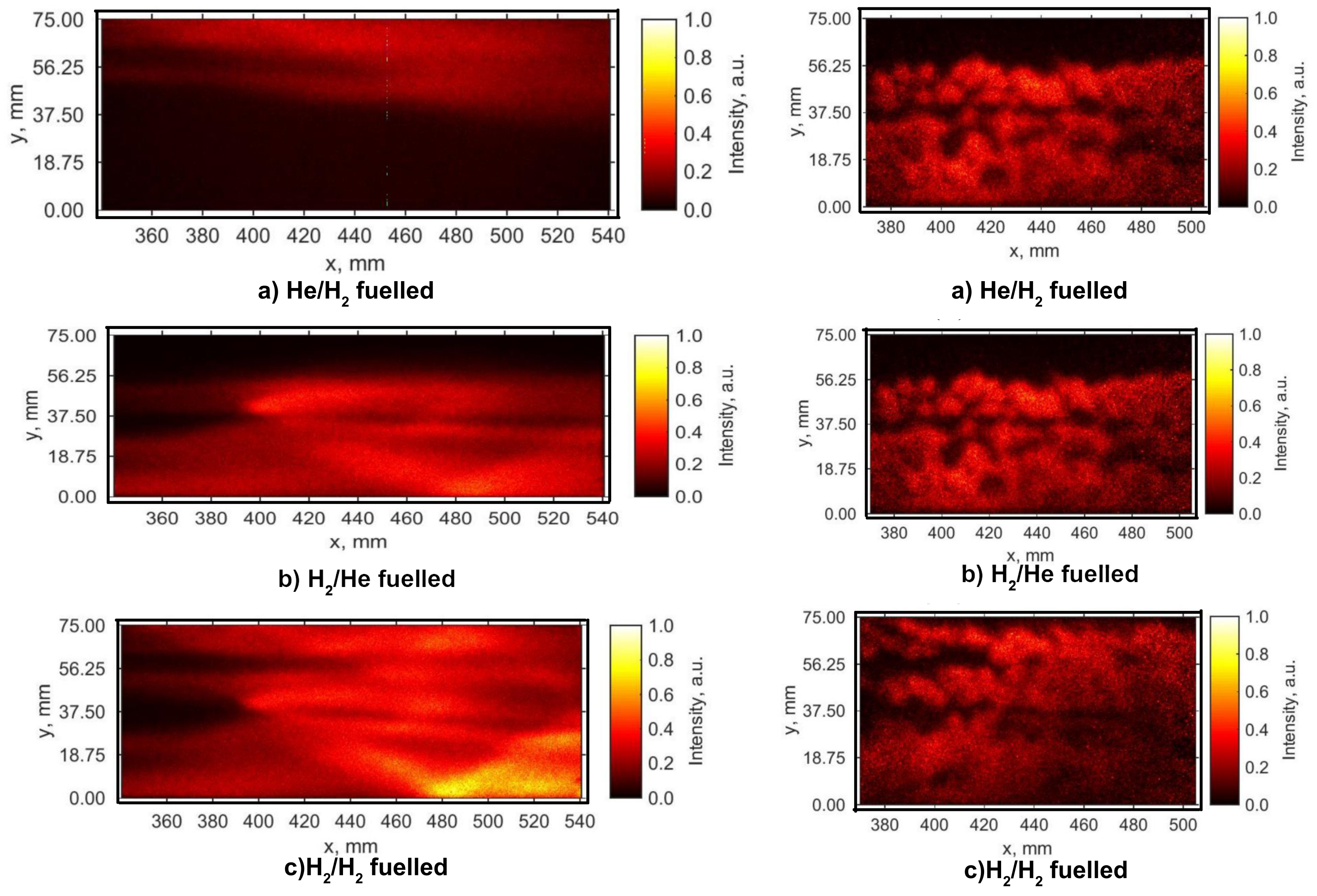
Vanyai et al. [106] did an experiment on thermal compression scramjet based on OH imaging [107], and found that such three-dimensional air inlet of supersonic ramjet can generate pressure and temperature gradients of the fluid. The combustion of any part of the combustor was suppressed by injecting combustion fuel, hydrogen, or non-combusting helium to check how the combustion of these parts affected the pressure and temperature of the entire flow field, the concentration and production of OH radicals was depicted by OH chemiluminescence and planar laser induction fluorescence (PLIF) images see (Figure 29) [108] so as to detect the chemical activity throughout the entire combustion process. The experimental results show that thermal compression is an effective method to increase the combustion pressure of scramjets, and thermal compression can effectively increase the chemical activity of the fuel and thereby the thrust of the engine can be improved.
In a study by Hossain [109], the theoretical value of thermal efficiency of ramjets was calculated based on the heat conduction equation. The thermal efficiency of ramjets mainly depends on numerical conditions at the inlet and outlet of the combustion chamber and the engine outlet. In another study, the effectiveness of scramjets based on the Brayton cycle [110] was primarily analyzed. The cyclic static temperature ratio ( T 3 / T 0 ) was the parameter emphatically discussed in this study, and changes in the velocity and temperature of the inlet and outlet of the combustion chamber, the unit thrust, the overall efficiency, and the thermal efficiency of the propulsion system were calculated under different T 3 / T 0 values. It was concluded that the change in T 3 / T 0 has some effects on the overall efficiency and thermal efficiency of the propulsion system, with the overall efficiency being the largest at a T 3 / T 0 ratio of about 2.5 when air-fuel mixtures and other parameters remain constant.
Based on computational fluid dynamics and finite element analysis, Rockwell et al. [111] measured the wall pressure of ramjet and the temperature of the flow field using the fluid diagnostic technology [112]. Moreover, the experiment also verified the reliability of finite element calculation of heat through a boundary temperature map of the flow path of ramjets. Figure 30 is a schematic diagram of the diagnostic device describing part of the flow path in the combustion chamber. On this basis, the premixing of fuel for dual-mode scramjets was further studied to improve the thrust of the engine [113], providing a feasible solution for the design of oiling channels for ramjets. In a study by Fiévet [114], the influence of unsteady heat on scramjets was investigated, and a numerical analysis showed that igniting the scramjet at an insufficient Mach number is an important reason for propulsion system failure. The potential research direction in the next step is to study how to design appropriate oiling channels and sensing systems to ensure that the engine can be ignited under sufficient Mach numbers so as to avoid combined propulsion failure.
Lou et al. [115] carried out a transient thermal analysis and thermal deformation study of the propulsion system of hypersonic vehicles in the cocooning state. In this study, the thermal analysis of the turbine engine in the cocooning state was first carried out. Additionally, the change of gap between the turbine rotor and stator in the cocooning state was analyzed. The data show that the lubricating oil’s temperature may exceed the limit if the bearings run too hot in the TBCC at Mach 6. Moreover, studies have shown that turbine engines may experience undercooling caused by the cooling flow, resulting in a reduction of the gap between blades at the top. This study provided a detailed transient thermal analysis method that is somewhat universal for determining the thermal management scheme by calculating the thermal loads and deformations of various components of the propulsion system.
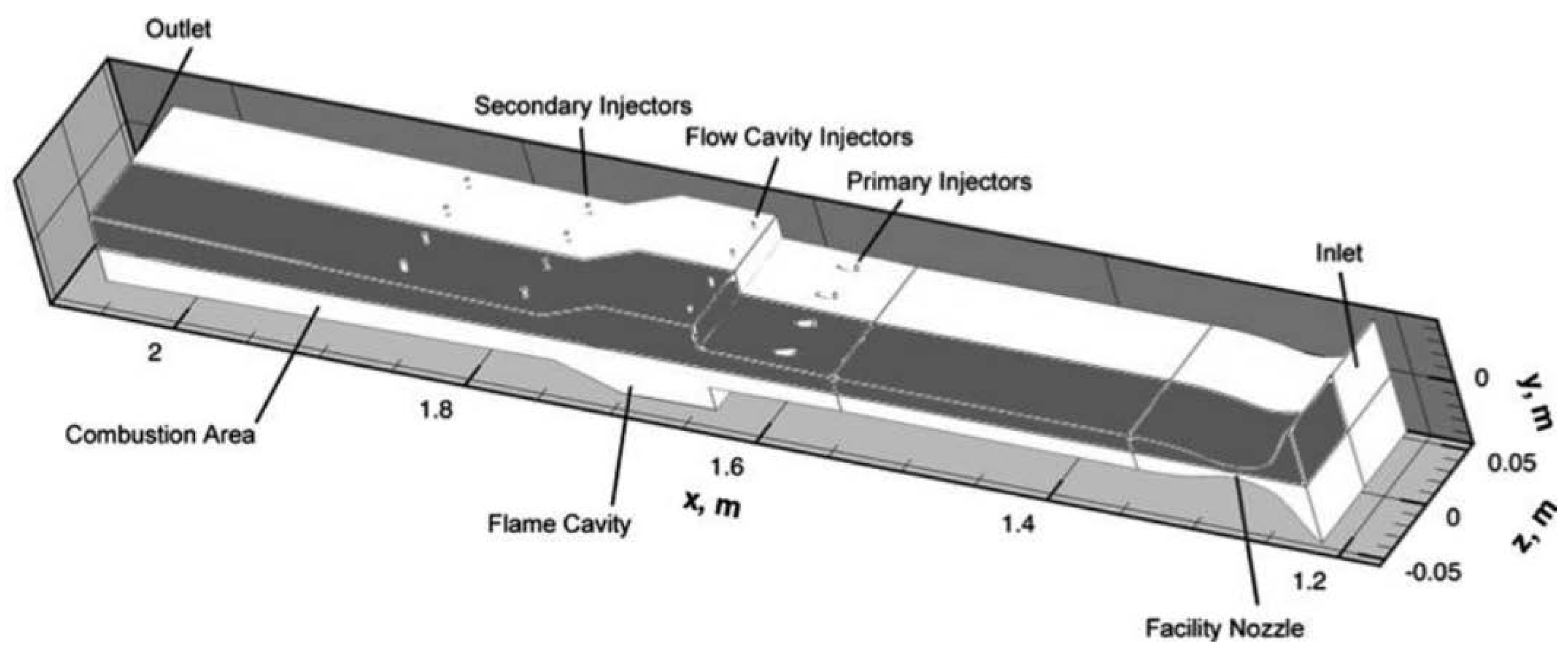
Some progress has also been made in the thermodynamic analysis and numerical modeling of various components of the propulsion system. In a study by Arun [116], the cascade fuel injector for ramjets was explored. The thermal load distribution of the exhaust nozzle was intuitively calculated through an ANSYS modeling of the exhaust nozzle (see Figure 31), and it was clearly indicated that only with the fuel as a coolant can the stability of ramjets be guaranteed under high-Mach flight conditions. Weigand et al. [117] carried out thermal load simulations on the cascade fuel injector in two flow field conditions: moderate and high temperature.
The main external flow field was modeled using LITA technology [118], and the conjugate CFD simulation with complex heat conduction, which coupled external loads and the internal flow field inside the injector, was applied to obtain a comprehensive assessment. In addition, the numerical simulation of the hot-gas conditions corresponding to the combustion experiment was also proposed, the results of which can be used not only to study the cooling mechanism and but also to optimize the numerical values of the internal flow paths so as to improve the cooling in regions with structurally high thermal stress. Figure 32 compares the experimental results and numerical simulations of the surface temperature of the injector.
Simsont [119] studied another numerical calculation model for thermal load of cascade oil injectors, and the spatial fourth-order multidimensional limiting process (MLP) [120] was used based on a compressible finite volume scheme [121] to simulate the flow field of combined propulsion. Coupled simulation of the vane-type column injector can calculate the flow field distribution, heat flux inside and outside the column, and the temperature distributed in the solid materials (see Figure 33), thus greatly contributing to the calculation of thermal conduction of components in thermal management.
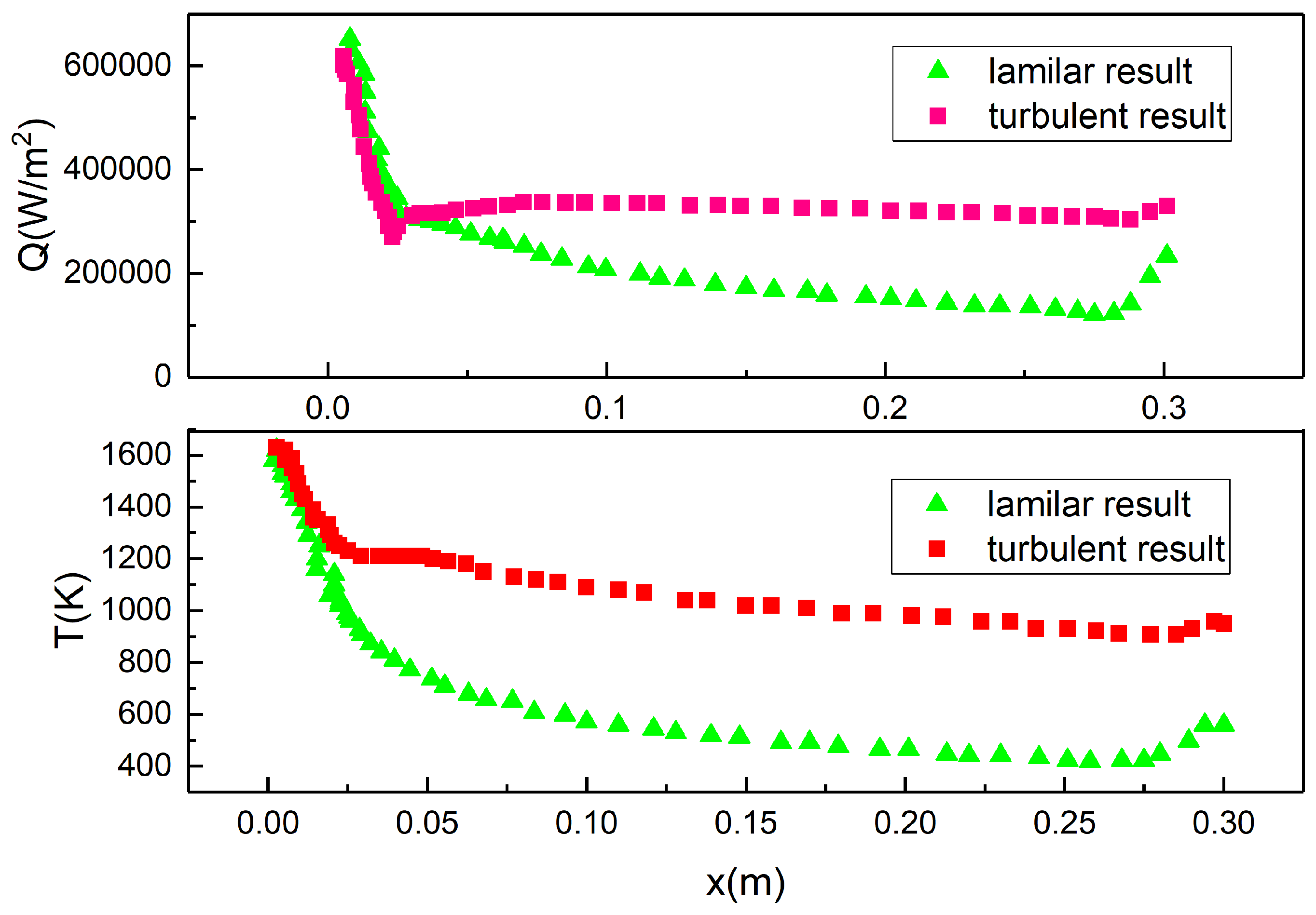
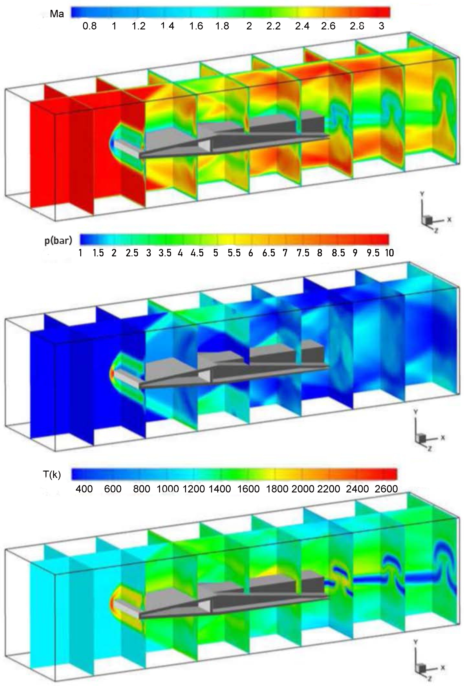
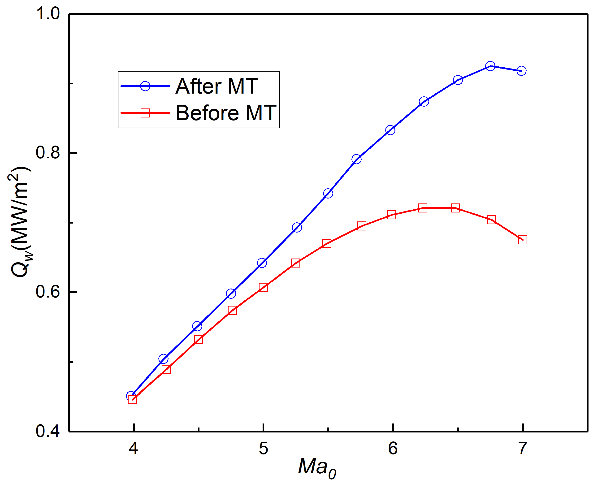
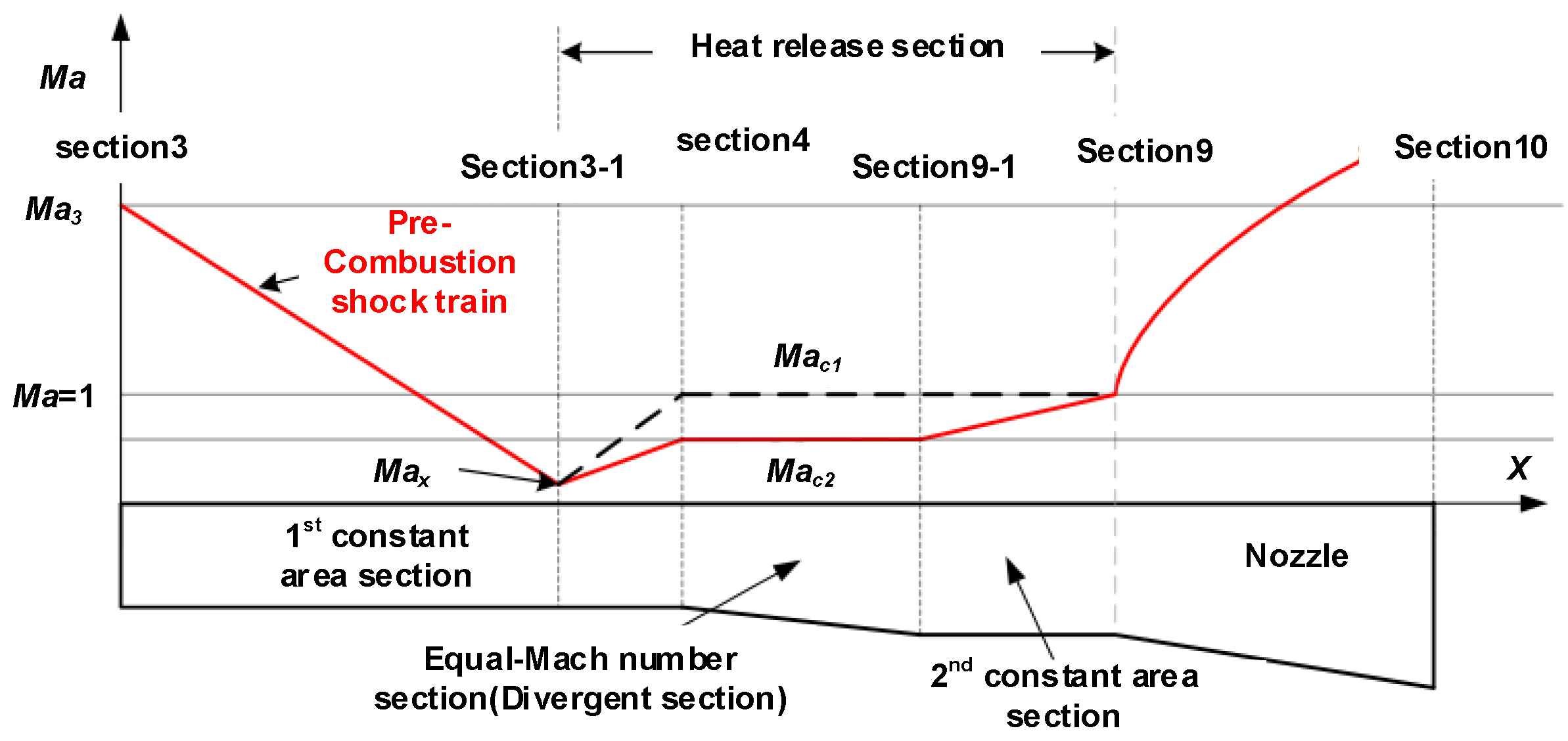
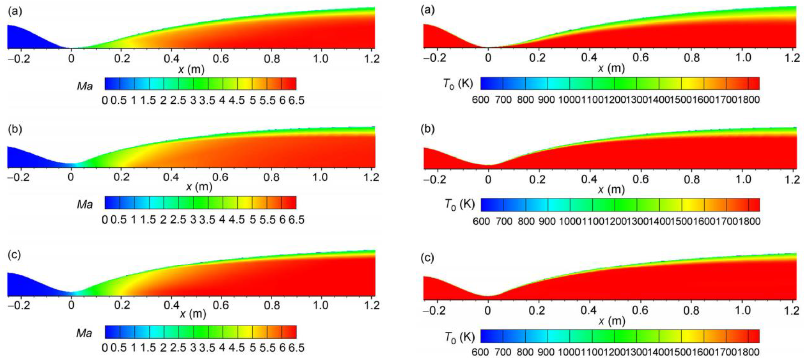
Xing et al. [122] studied the influence of different constant thermal throat areas of the exhaust nozzle on thermal blockage [123] of dual-mode scramjets [124]. Methods like the ground test, pressure measurement, and three-dimensional numerical simulation connected to models were used in the study, and the experimental results show that the constant throat area contributes to ignition of the combustion chamber and retention of the flame, and structures with short constant areas increase the heat release in the combustor and reduce entropy generation, thereby increasing combustion efficiency. These experimental results provide a reference for the design and thermal management of the exhaust nozzle of the propulsion system. Yang [125] studied the thermal behavior of the isolator during combustion mode transition in a dual-mode scramjet. According to this study, combustion mode transition has a relatively large impact on the thermal behavior of the isolator, which is manifested by a significant change in the heat flux and wall temperature of the isolator, as shown in Figure 34. In a study by Chen [126], characteristics, e.g., Mach number, of dual-mode scramjets were explored. By analyzing the thermal process cycle [127] which can be equivalently regarded as the actual thermal process of the combustor of a dual-mode scramjet, the performance limits of a dual-mode scramjet were optimized. Figure 35 shows the working principle of the combustion chamber of a dual-mode scramjet.
Xie et al. [128] proposed a new functionally-graded-layer-composite structure (FGLCS) applied to the exhaust nozzle, which consists of a passive thermal protective layer made of ultra-high temperature ceramic (UHTC) composite material, a high temperature insulating material interface layer, and an active thermal protective layer made of alloy. In this study, the transient thermal stress relief characteristics of fuel injector plates and struts with FGLCS under aerodynamic heating were studied using the finite element method. Compared to conventional UHTC, FGLCS can significantly reduce the thermal stress of the structure. In addition, experiments in a combustion environment show that the FGLCS material yields better repeatability as well, as shown in Figure 36. Future studies in this regard may involve further verification of wind tunnel fuel injection and combustion as well as further improvement and optimization of FGLCS.
The latest studies on hypersonic air inlets mainly focus on improving the performance of combined propulsion and reducing the heat flux by optimizing the design of the physical structure of air inlets. Recent studies mainly include those carried out by Zhang [129], Klock [130], Kline [131], Maxwell [132], and Goodwin [133]. These studies have not yet involved calculation or simulation of the thermal load of the air inlet. Besides, an important research direction of the air inlet is that due to the mode transition of combined propulsion system, the thermal load might mutate because of change in aerodynamic shape during the mode transition of the air inlet [134], which is a problem of thermal protection and management that cannot be avoided in the design of combined propulsion systems.
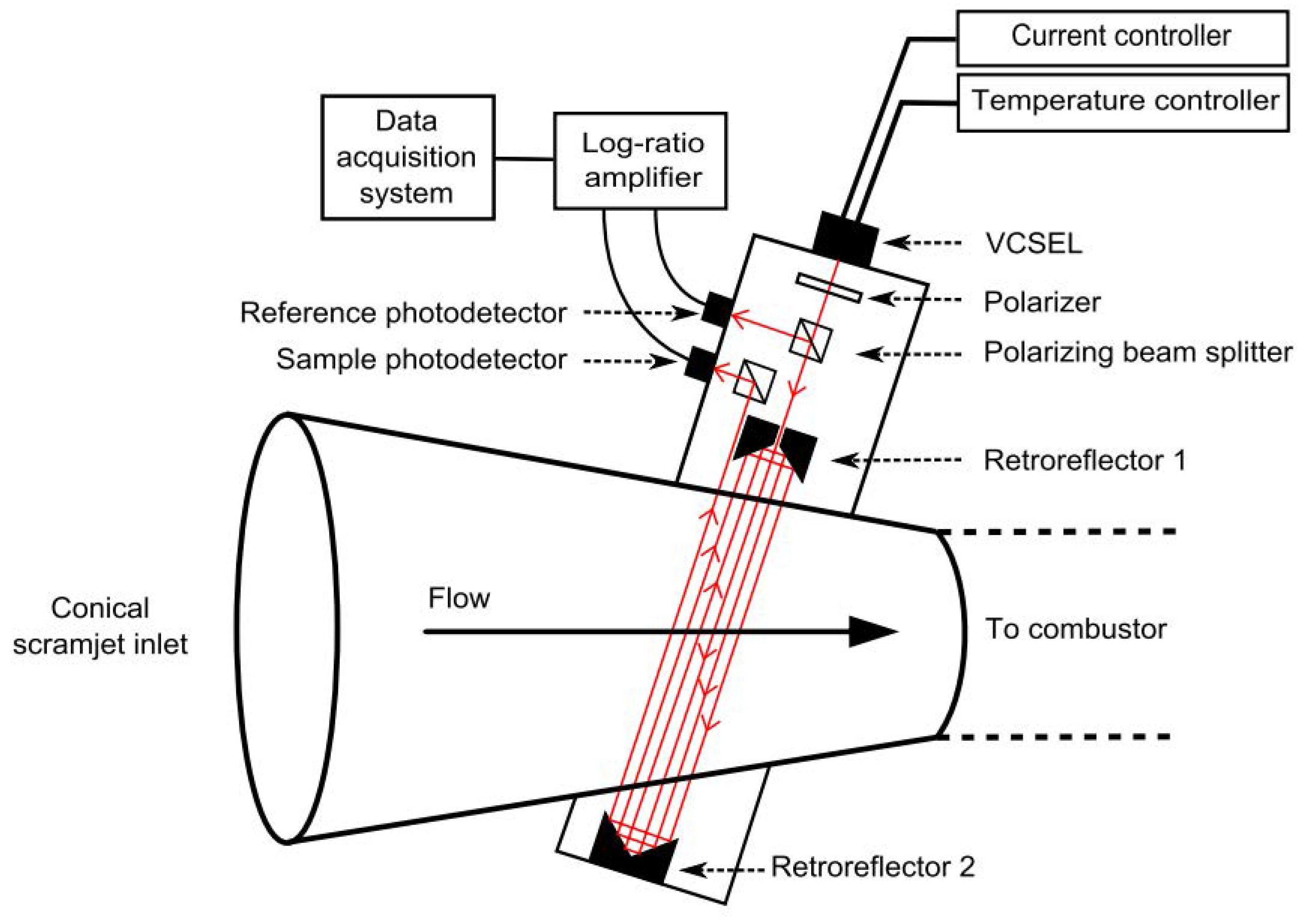
Krishna [135] proposed a method to measure the angle of attack at the air inlet of a gas supersonic combustor and determine the Mach number of the gas (see Figure 37) based on the design idea of the sensor with tunable diode laser absorption spectroscopy. However, the limitation of this method lies in the fact that the measuring accuracy is greatly affected by flight noises. Therefore, future researches on this method may focus on reducing the correlation between measuring accuracy and flight noises through the optimization of relevant algorithms (hypersonic flight noises may be unavoidable, and Huang et al. [136] once conducted a study to simulate hypersonic flight noises). Kurtz et al. [137] also used tunable diode laser absorption spectroscopy as the sensor of air inlet temperature and flow field velocity (see Figure 38), pointing out that increasing the length of air inlets helps improve accuracy of the sensor. Jin [138] studied thermal parametric conversion induced by air distortion in hypersonic tests with tunable laser diode. In conclusion, the sensor with tunable diode laser absorption spectroscopy has the potential to be applied in measuring physical parameters of air inlet flow field of propulsion systems.
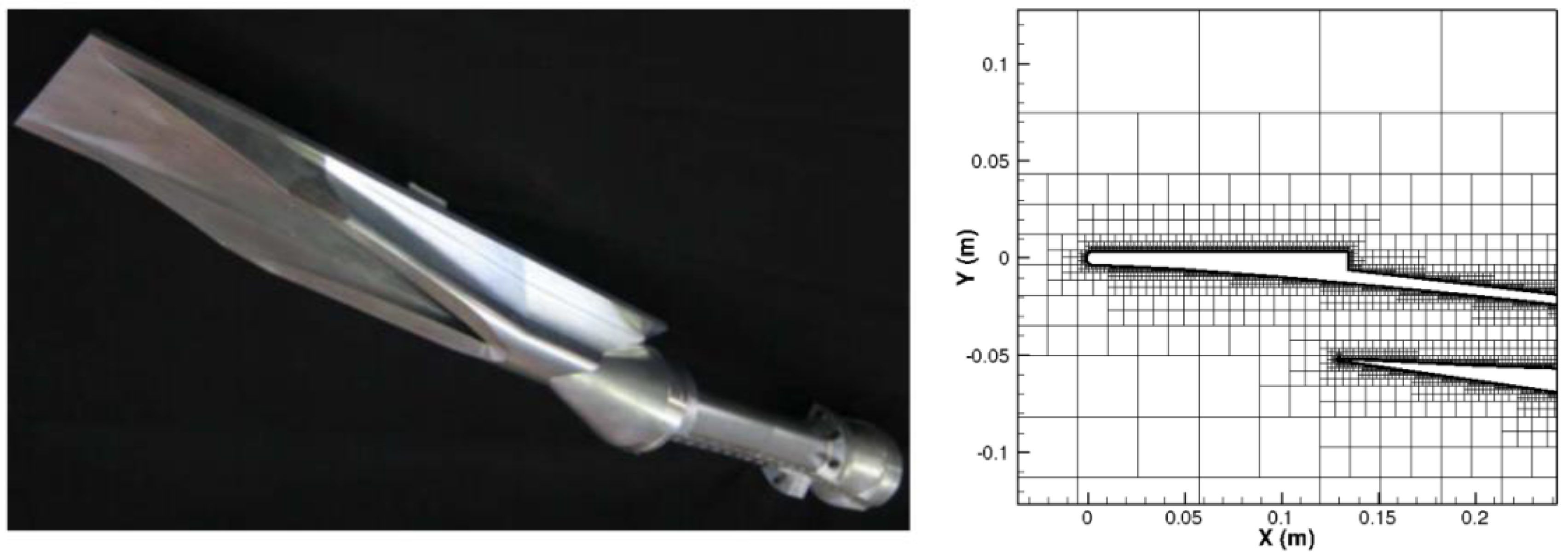
In a study carried out by Chang et al. [139], it was proposed that ignoring the aerodynamic thermo-elastic deformation may lead to high heat flux entering the engine surface, and the effect of aerodynamic thermo-elastic deformation on the performance of two-dimensional hypersonic air inlets was investigated. Chang et al. [140,141] pointed out the necessity to develop a method of detecting new flow patterns and characteristics under the influence of flow-combustion coupling in the complicated flow environment of hypersonic air inlets. In a study by Ferguson, the Ram-Scramjet model [142,143,144] was used to analyze the heat flux and load [145] at the air inlet of the propulsion system, and a quasi-one-dimensional flow field solver with real modeling capabilities was developed to be encoded in the object-oriented Fortran [146] and then incorporated into the NURBS-based Cardiac-Torso, NCAT original model [147]. The numerical analysis results show that the improved Ram-Scramjet performs well at low Mach numbers, yet it is unable to well demonstrate the aerodynamic heating of high-speed flow field on the air inlets at high Mach numbers. The one-dimensional flow field solver remains to be further corrected so that heat flux at the air inlets can be consistent with the experimental data at high Mach numbers. Additionally, the aerodynamic energy exchange was calculated with the Landau-Teller formula [148] and the Cartesian grid [149] solver was used to resolve the temperature and flow rate of the air inlet flow field [150] (as shown in Figure 39).
Gopal et al. [151] conducted a reduced-order analysis of the scramjet inlet and introduced a reduced-order model for performing rapid parametric studies of the air inlet operation of a typical scramjet. The theory of ideal gas flow [152] and the boundary layer theory [153] were applied to analyze the operation of air inlets through MATLAB modeling (see Figure 40). The experimental results were compared with the numerical results to ensure the reliability of the reduced-order model. Since this model can realize rapid parametric studies, it has the potential to significantly reduce the computational cost for hypersonic thermal management and flow field coupling. Klock et al. [154] also established a non-linear thermal reduced-order model for hypersonic aircrafts. It can be seen that reducing the computational complexity of numerical analysis and coupling through the reduced-order model has become a hot method for rapid analysis of heat flux in thermal management.
Cheng [155] carried out a thermodynamic analysis of the exhaust nozzle of ramjets based on wall cooling. In a study by Chang [156], the temperature and pressure distribution of the exhaust nozzle flow field were explored by conducting an experiment on the hydraulic piston rod sensor in the exhaust nozzle. Based on the one-dimensional thermodynamic modeling of the exhaust nozzle, the thermal load of the exhaust nozzle can be calculated to complete the assessment. Figure 41 shows the model diagram and calculation process of the exhaust nozzle. Xing et al. [157] carried out numerical analyses of the heat flux of two-dimensional, three-dimensional, and axially symmetrical nozzles (see Figure 42), the distribution of flow rate and temperature inside the three kinds of nozzles were simulated through the computational fluid dynamics model, as shown in Figure 43).
The analysis of the combustion chamber temperature is of great importance to judge whether the temperature of the inner wall of the combustion chamber is within an allowable range and to design the corresponding thermal protection and management systems. However, traditional one-dimensional heat conduction analysis is not accurate enough to analyze the combustion chamber wall temperature because multi-dimensional solutions are required. An algorithm that conducts a Fourier transform of the heat flux function is entirely possible to be applied to measure the combustion chamber temperature. In a study by Avallone [158], an algorithm was proposed to measure heat conduction in hypersonic flow environments at low computational costs. Combining the recursive least squares method [159] and the trust-region-reflective algorithm [160], this algorithm efficiently reduces the computational amount by conducting discrete Fourier transform [161] of the discrete heat flow function and optimizing the correlation coefficient. The thermal results were calculated based on the synthesized data, and the feasibility of this algorithm was verified through a wind tunnel experiment at Mach 7. This algorithm is very instructive for measuring the heat conduction of the combustion chamber in a propulsion system. In addition, the results were experimentally verified, and the accuracy of the algorithm was ensured to some extent, which is also one of the benefits of this research result.
Shahverdi et al. [162] made a bifurcation analysis of the aerodynamic force under hypersonic flow and the functional gradient curved plate [163] under thermal load. The classical plate theory was used to model the structural processing and the nonlinear structure was described by the von Karman strain-displacement relationship. To combine the applied supersonic aerodynamic loads, the third-order piston theory [164] was used to simulate unsteady aerodynamic pressures in this flow state, the temperature distribution in the direction of thickness was calculated by solving the one-dimensional steady-state heat conduction equation, and the generalized differential quadrature (GDQ) method was combined with the fourth-order Runge-Kutta method [165] to discretize and solve the equation. The reliability of the algorithm was guaranteed by the comparison of the results with currently available data. This algorithm can analyze the air-heat load of the curved plate in the hypersonic range, which is of certain reference value for calculating the thermal load of curved components of the propulsion system. At low Mach numbers, turbine engines and rocket engines mainly serve as the propulsion systems, and ramjets usually work as the propulsion systems at high Mach numbers.
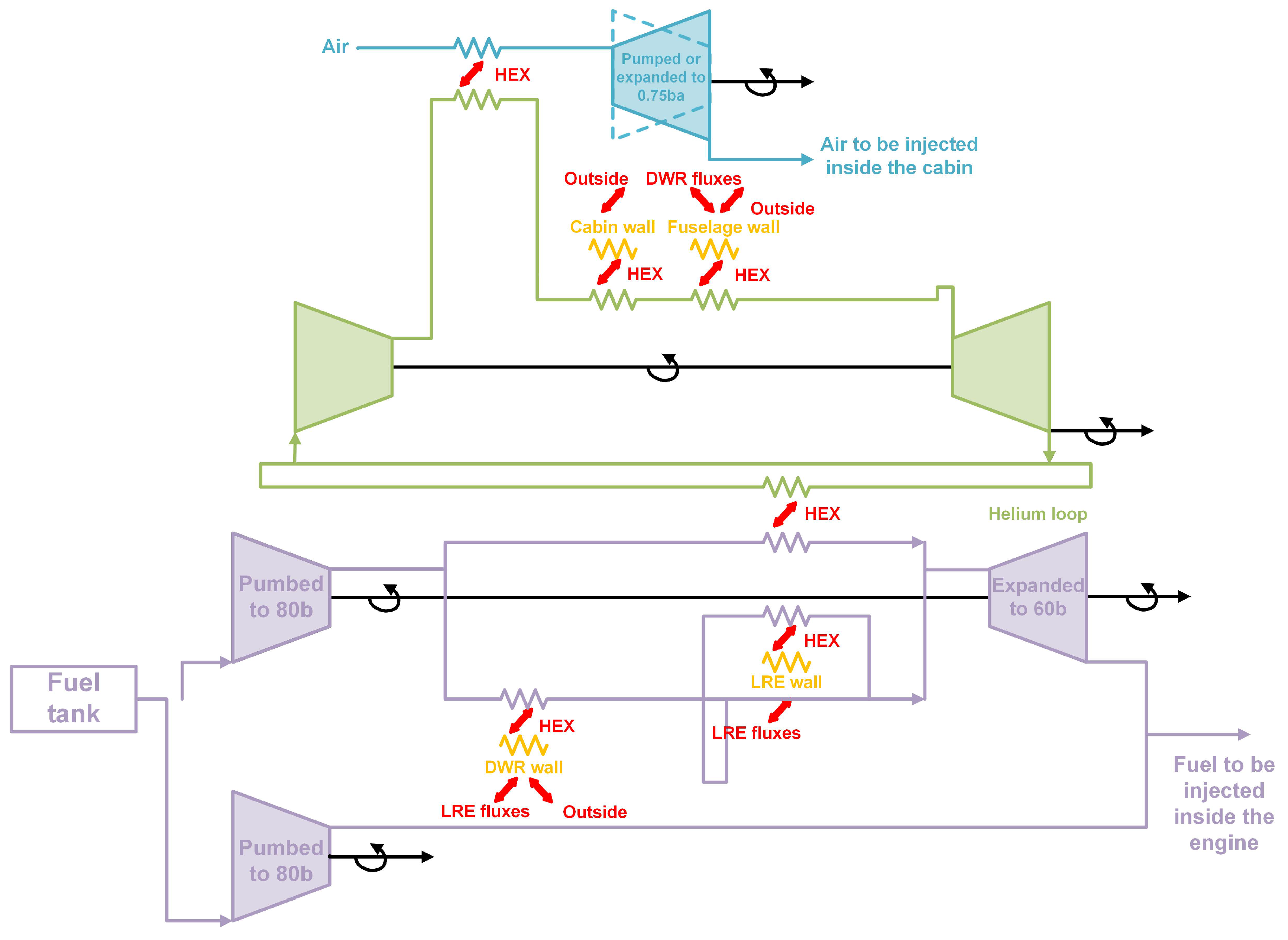
In a study by Langener [166], it was suggested that the fuel should enter the combustion chamber and the outer wall of the exhaust nozzle to be cooled before the combustion, so as to make full use of the waste heat to preheat the fuel. The MR2 aircraft in the European HIKARI project was evaluated in detail at Mach 8. The thermal and energy management cycle structure of this aircraft is shown in Figure 44.
In the cycle structure of the aircraft, a portion of the gas fuel is used to cool places like the compartment, the fuel is compressed and mixed with the air to become the hydrocarbon fuel used to cool the propulsion system, the fuel then goes through the turbine chamber to provide propulsion energy, and finally enters the combustion chamber. The diagram of thermal management cycle of the fuel for MR2 is shown in Figure 45 where the heat transfer considered is mainly between the inner wall of the engine room and the outside air, between the inner wall of the engine room and the fuel tank, between the equipment and the fuel tank, between the equipment and the Dual Mode Ramjet, DMR [167], and between the DMR and the outside air. In addition, the heat fluxes of DMR and Liquid Rocket Engine, LRE [168] were also taken into account. It is worth noting that helium was used as a closed-loop system for the intermediate fluid in this cycle. Some fuel-based open-loop cycles were analyzed in the MR2 design, yet for safety reasons, it is more reasonable to use an intermediate liquid to cool the fuselage than the fuel. Depending on the mode of the aircraft, the cooling circuit can follow different paths. In this thermal management loop, the simulated parameters include Heat Exchanger, HEX [169], the mass fractions of different pipes (He, H 2 and Air) around the wall, and the thickness of the insulation layer.
In a study by Jasa [170], a method for analyzing the lubricating oil system of aero-engines based on thermal management technologies was proposed. Three approaches to cool the lubricating oil system were presented, i.e., the cooling method with force conversion valve, the cooling method with main and auxiliary cooling zones, and the cooling method with the auxiliary radiator installed in the gear pump circuit. Preliminary studies have shown that the cooling method with main and auxiliary cooling zones meets the thermal management requirements, yet at this point, the temperature of the lubricating oil system has reached its limit boundary, so it is of great significance to develop the optimal design of corresponding radiators. Yan et al. [171] simulated and optimized the lubricating oil system based on the MATLAB/Simulink model which proved to be valid according to its comparison with the Flowmaster software. It is also more convenient to conduct a co-simulation of this improved model and other software such as GasTurb. Moreover, such co-simulation may be of great value in the coupling calculation of the lubricating oil and fuel systems, which is necessary for optimizing the modeling of the lubricating oil network for the thermal management of propulsion systems.

3.4. Thermal Protection Systems

In this section, mutual coupling between the subsystems of different modules of thermal management, as well as simulation of the thermal management system, will be introduced. As thermal management involves a large number of modules, how to realize the unified management of independent subsystems has become one of the important breakthroughs to be made for researches on thermal management systems [172]. In addition, since multi-system coupling and thermal environment simulation require a large amount of calculation, optimizing the calculation method and flow of the program can save calculation time, realize rapid simulation of thermal environment, and improve the precision of system coupling and simulation. As active and passive thermal protection technologies have been fully introduced in the second section, unnecessary details will not be given in this section.
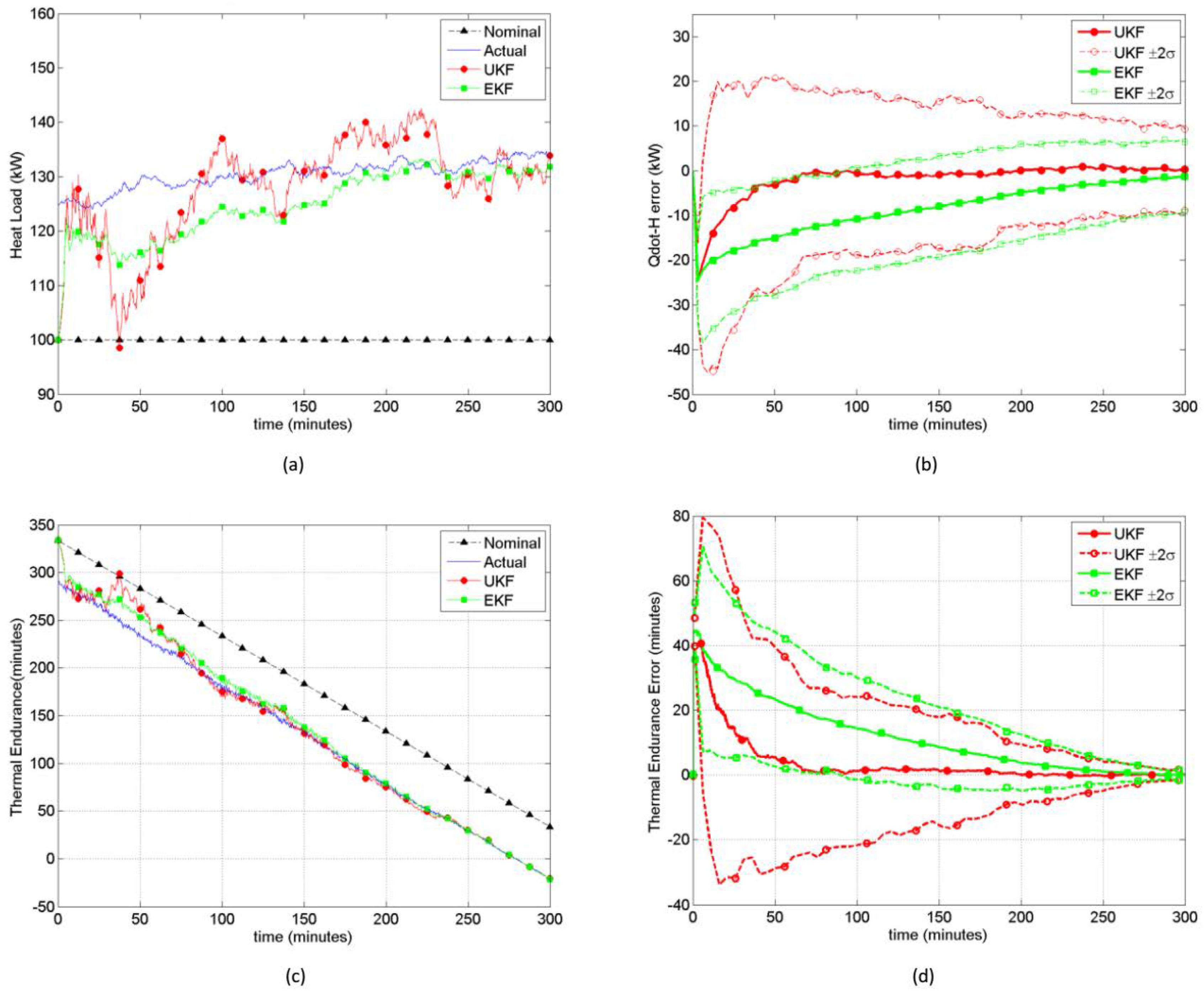
In terms of thermal environment simulation, Desimio et al. [173] proposed an online forecasting scheme for fuel thermal management system. This study mainly aimed to predict and calculate differences that may exist between the thermal management model and the real conditions of the aircraft. First of all, for the split heat exchanger-drain-recirculation (SHEDR) cycle of fuel, the relationship among fuel energy, temperature, and quality was calculated based on the heat balance equation, and a discrete-time scenario model was presented to estimate differences through UKF and EKF (Unscented and Extended Kalman filters) [174,175]. Based on the data analysis of the calculation example, as shown in Figure 46, differences between results obtained by the thermal management model and the actual situation were demonstrated, which shows the importance and necessity of paying attention to such differences and developing the online thermal management system.
In a study by Neera Jain [176], a method was proposed to improve thermal management of the fuel based on optimizing the objective function, and it was pointed out that fuel thermal management systems for aircrafts, including hypersonic vehicles, should be formulated systematically and specific transient behaviors should be synthesized. The thermodynamic method for the minimum-energy failure of complex propulsion systems [177] was used to determine the optimal fuel use scheme that satisfies a given transient thermal load, with the advantage of plug and play. In addition, since this algorithm is notable for the automatic definition and quantification of invalid components, it is relatively applicable to operating conditions with comparatively complicated computational conditions and a large computational amount, e.g., the propulsion system of hypersonic vehicles. Figure 47 is a schematic diagram of the calculation model. A further plan of the study is to optimize subsystems of the aircraft engine to realize thermal management of the propulsion system. This energy-based approach has great potential to be applied in thermal management of propulsion systems.
Doman’s study [178] on thermal management of aircrafts based on optimal cruise altitude and rapid analysis of aircrafts was cited at the 2015 AIAA Guidance, Navigation, and Control Conference. A method to conduct quick analyses of fuel cycle thermal management by solving differential equations in order was proposed. These differential equations were derived from the mass and energy conservation equations in the fuel cycle. The modeling of the heat transfer in this study is shown in Figure 48. The study mainly aimed to replace the problem of solving the boundary values of partial differential equations with the problem of working out non-linear roots of the differential equations, so as to reduce the computational amount and achieve rapid analysis. Additionally, the feasibility of this method was verified by a calculation example. By transforming a complex problem into a relatively simple problem, the proposed method is of value to the simulation of complex flow field and thermal environment in the thermal management of hypersonic vehicles.
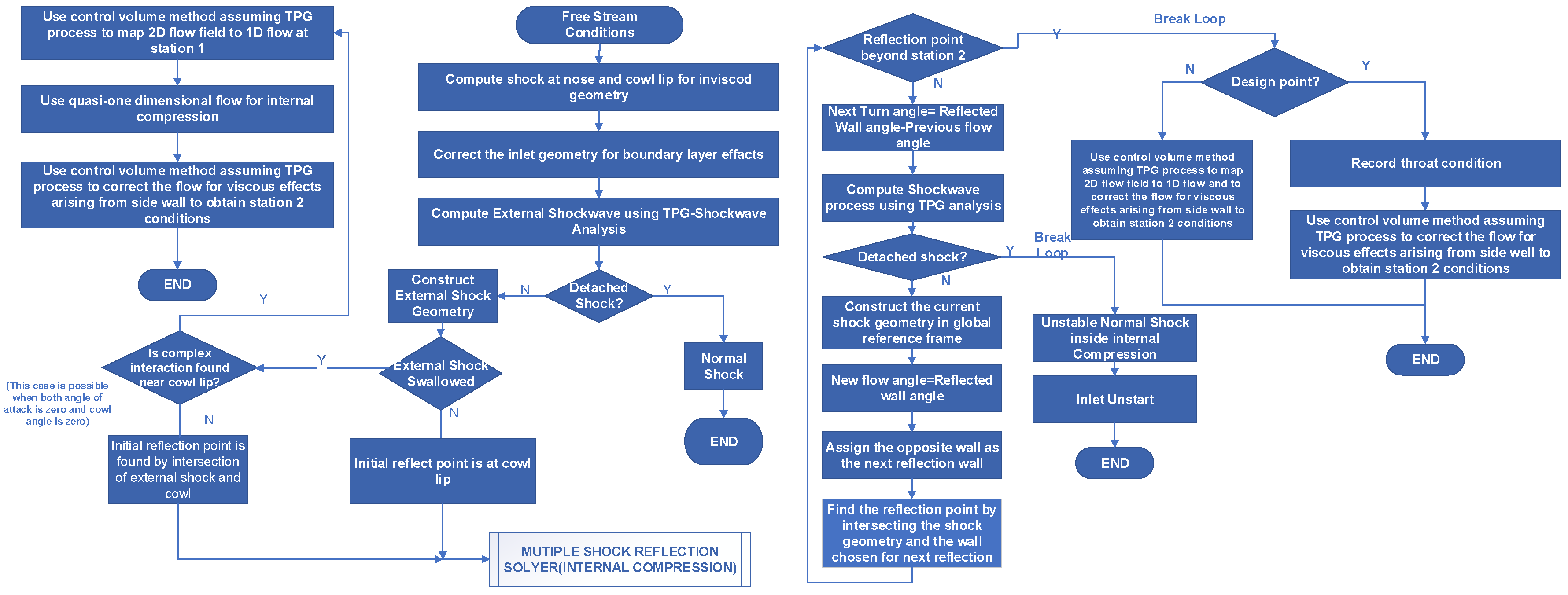
In the LAPCAT-II project, the CFD code (internal and external flow path simulations) was combined with the One-dimensional simulation tool used in high-speed air intake propulsion systems to conduct an approximate modeling of the combustion process. With the outflow of the combustion tube as the CFD inflow condition, detailed numerical simulation of the internal flow field was avoided and the simulation computational amount was reduced.
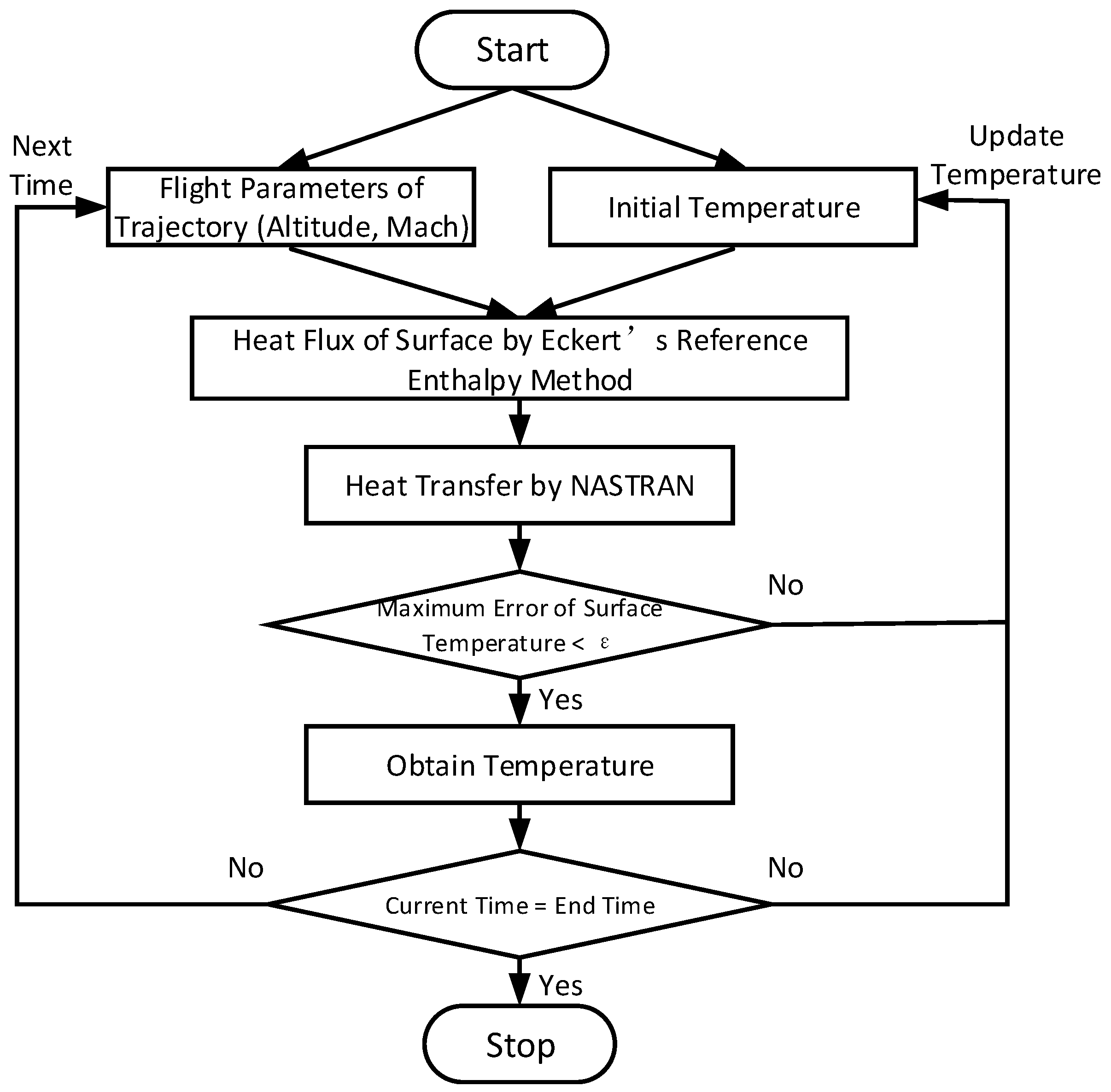
Regarding the coupling of subsystems, Chen et al. [179] studied the coupling of aerodynamic heating, radiation heat transfer, and heat conduction in hypersonic vehicles with the flow chart and solving procedure of coupling analysis shown in Figure 49. The results show that the temperature obtained by coupling solution is relatively accurate, with a relative error lower than 10% most of the time. The model established in this study is about the wing part, yet if a three-dimensional model of the air inlets of the propulsion system is established and calculated through coupling analysis, it is possible to obtain a relatively accurate solution of the inlet temperature and complete the thermal load analysis. Capra et al. [180] used the iterative algorithm to conduct a structural coupling of flow field, convective heat transfer, and wall temperature based on two-dimensional and three-dimensional models, which is likely to be applied to wall heat transfer in the combustion chamber of ramjets. Chen also proposed an aerodynamic modeling approach with less orders based on surrogate [181]. However, no study has been carried out on the correlation between this theory and relevant dynamical system models. Reinert et al. [182] simulated the coupled conjugate heat transfer of the scramjet inlet at a Mach 8 flow field. In order to effectively simulate the aerodynamic interaction, the fully coupled conjugate heat transfer solver, US3D, was developed, which can be further applied to the geometrical shapes of two-dimensional and three-dimensional scramjets.
Davuluri et al. [183] focused on the impacts of thermal degradation of debris particles on hypersonic environments. Bidirectional coupling was carried out between spallation code and hypersonic aircrafts and the dynamic CFD solver was used to assess influences of fissure particles in the flow field. The simulation results show that the thermal degradation process has a certain influence on the temperature distribution in the flow field. The development of this study is helpful to improve the simulation accuracy of the high temperature flow field in the propulsion systems.
Trelewicz et al. [184] designed an equation and directly embedded it to the sensor to accurately measure the heat flux of walls inside the combustion chamber of scramjets in real time. The heat flux sensor used N-type (nickel-based) thermoelectric materials and yttria-stabilized zirconia as a multilayer thermopile of the intermediate thermal resistance layer. The sensitivity of the heat flux sensor was verified using a conduction-based test method, demonstrating that the sensor’s performance is consistent with the calculated theoretical sensitivity. In addition, the sensor was installed in the flow path of the RC-18 scramjet at Wright-Patterson Air Force Base for testing under simulated flight conditions at Mach 5. The values reported by the sensor are consistent with those obtained by thermal measurement of area average, which guarantees the sensitivity and reliability to some extent. Moreover, this write-through sensor can also detect high frequency heat load oscillations which cannot be manifested through the collinear thermal imager. Therefore, the write-through sensor has certain potential to be applied in real-time diagnostic and control of heat load of scramjets.
Feng et al. [185] explored the heat transfer problem of supercritical hydrocarbon fuel. In this study, a two-dimensional numerical model and an unstructured grid were constructed to describe the thermophysical properties of hydrocarbon fuel in the cooling channels, accurately predict flow field changes in the cooling channels, and couple the influences of parameters in the chemical reaction flow field such as speed, temperature, and pyrolysis. This study made the modeling of cooling channels more accurate, but it only provided a qualitative description of the coupling of flow, heat transfer, and pyrolysis. Therefore, how to quantitatively describe the coupling of these factors is the key problem to be solved so as to reduce calculation for modeling and make the results more accurate, which is also the direction for further researches to be carried out(see Figure 50).
In a study carried out by Behbahani [186], a tree structure was proposed, and a fully licensed digital engine system (SFADEC) was used to control the decentralized hardware and dynamical feedback control, so as to dynamically distribute resources of the whole system and complete the thermal and energy management of the engine. Figure 51 is a schematic diagram of the distributed embedded architecture in this structure. Figure 51 also shows an information flow chart of the control architecture of this structure. The development and maturity of this technology is of great significance for coupling subsystems under the thermal management of propulsion systems and has great potential for the application of thermal management. Nevertheless, to apply this tree structure to thermal management of engines, further experimental verification and logic optimization need to be carried out to reduce the computational cost.
Marcos et al. [187] conducted a ground test to establish a model of the entrance of scramjet air inlets through additive manufacturing. Figure 52 shows the scramjet model which was used in the ground test. Due to its advantages in terms of time and cost, additive manufacturing is replacing the original metal material processing model to be used in hypersonic ground tests. This ground test performed FEA prediction [188], HAP calculation [189], CFD simulation and Schlirien image [190], and finite element prediction through a structural response to the additive manufacturing model under expected mechanical and thermal load, demonstrating the reliability for the additive manufacturing structure to be applied in wind tunnel experiments in both aerodynamics and thermal structure. By reducing the cost of wind tunnel experiments, it is possible to improve the accuracy of designing thermal protection and management structures of the air inlets. Besides, simulation experiments can also be conducted on other components of the propulsion system through additive manufacturing, and high temperature resistance printing materials can be developed to overcome the high temperature, which may be one of the future development prospects of this experiment.

4. Prospect

4.1. Overview of Future Research Directions

Regarding thermal protection for propulsion systems of hypersonic vehicles, future research will focus on further research and development, R&D of CMC materials for passive thermal protection technologies. The direction for future researches is to seek CMC materials with stronger heat-shielding performance, oxidation resistance, and impact resistance by further optimizing the composition of CMC materials and conducting experimental tests of harsher corresponding thermal environments. In addition, modeling the behavior of CMC materials is another orientation for future researches, for an understanding of material behavior will improve the durability of CMC coating and can guide the selection of suitable materials. Since active thermal protection technologies involve relatively high Mach numbers, the temperature of the incoming flow in convective cooling is relatively high, so the cooling performance is limited. Therefore, later researches should mainly focus on sweat cooling, circulating cooling, and air film cooling. For sweat cooling, the cooling effect and reliability in complicated hypersonic flow environments should be further studied. As the sweat cooling preparation of turbines and other components belongs to the field of precision machining, seeking preparation methods with relatively high repeatability and reliability is an important approach to effectively reduce the preparation difficulty and cost, which is also one of the directions for future researches in this field. Circulating cooling is mainly combined with thermal management of fuel, and studies show that the efficiency of circulating cooling can be effectively improved by promoting the efficiency of thermal management of propulsion systems. Moreover, since components of thermal protection systems of combined propulsion system are usually a combination of passive and active thermal protection, it is foreseeable that another possible research direction in the future is to study the coupling of active and passive thermal protection systems to maximize the thermal protection system’s efficiency at higher operating temperatures.
On the topic of thermal barrier coating technologies for propulsion systems of hypersonic vehicles, traditional 7–8 YSZ materials are no longer able to meet the thermal protection requirements of hypersonic vehicles. From the perspective of materials, future studies will focus mainly on improving the thermal insulation properties of the material by mixing YSZ with multicomponent oxides and replacing YSZ with rare earth zirconate or other materials. Considering the structural level, multi-layer and gradient structures with good performance in thermal protection and low rates of chemical reaction and corrosion should be developed to replace the classic the double layer structure. Since it is comparatively difficult to prepare both the multi-layer and gradient structures due to poor repeatability, seeking preparation methods which are less costly is also one of the research directions in the future. In terms of preparation, exploring new technologies based on previous APS and physical vapor deposition technologies will be one of the research focuses in the future, e.g., how the performance of thermal barrier coating in high temperature and oxidation resistance can be optimized by SPS and plasma activated electron beam physical vapor deposition. From the perspective of failure mechanism, there are currently few studies on factors that cause thermal barrier coatings to fail and fall off. Therefore, further studies on the failure of thermal barrier coatings caused by thermal stress, external factors, and oxides are of instructive significance to researches on materials, structure, and preparation of thermal barrier coatings. Hence, further exploring the failure of thermal barrier coatings is also needed to improve the reliability of thermal barrier coatings in the future.
There are currently few studies on thermal management technologies for propulsion systems of hypersonic vehicles. Most studies focus on thermal management of the fuel, whereas there are few studies on thermal management of the lubricating oil network and the coupling of oiling channels. In addition, in the past, the thermal management of engines was often separated from the thermal management of the aircraft system. However, since the concept of integrated aircraft/engine technology has been proposed, more attention will be paid to the coupling of thermal management of propulsion systems and that of aircraft systems in the future. The specific and overall directions for future researches on thermal management of propulsion systems of hypersonic vehicles are listed in Section 4.2 and Section 4.3.

4.2. Specific Directions of Future Researches

  • It is necessary to accurately simulate and study the temperature distribution of each component of the propulsion system in the hypersonic flow field so as to ensure that the thermal management of aircrafts can guarantee that the propulsion system is within the temperature envelope.
  • Further analyses should be carried out on one-dimensional heat conduction and heat transfer calculation models of fuel oil, lubricating oil, and air, so as to establish accurate one-dimensional heat conduction equations.
  • For thermal management of fuel oil, LNG has better heat sink and cooling performance than current hydrocarbon fuels. Since LNG possesses the potential to be applied in thermal management of fuel oil, further researches remain to be conducted on the high cost and high storage space of LNG as a fuel.
  • There are currently few studies on oiling channels of fuel and lubricating oil in the propulsion system. One of the focuses of future researches on thermal management of aircrafts is to carry out numerical simulation of the cooling effect of oiling channels of fuel oil and lubricating oil on the propulsion system proposed in previous studies and to optimize the oiling channels based on the simulation results.

4.3. Overall Directions of Future Researches

  • In future researches, a model for calculating the energy interaction among the flow paths of air, fuel oil, and lubricating oil should be established, and how the flow paths mutually influence each other should be taken into consideration, so as to improve the accuracy of flow path design. The efficiency of aircraft thermal management should be improved by exploring the optimal design of the flow path network.
  • The matching technology and system control strategy of the thermal management system and engine system should be optimized. Real-time and rapid thermal management systems should be studied by optimizing the tree structure and feedback control cycle of thermal management. The efficiency of thermal management systems can be improved by reducing the computational amount of thermal management systems through improving the objective function and parameters of thermal management systems.
  • It is important to further study the thermal management model of propulsion systems of hypersonic vehicles during mode transition, and to probe into the thermodynamic calculation model and flow path design of multiple engines working together (e.g., turbine engine with rocket engine, and rocket engine with ramjet) during mode transition.
  • Based on the concept of integrated aircraft/engine technology, thermal management of the propulsion system and aircraft thermal management are no longer operated as two independent submodules. Establishing a calculation model coupling the thermal management system of the propulsion system and the aircraft thermal management system will be a significant research focus in the future.
  • Current studies are mostly confined to thermal management of various components of the propulsion system, whereas there are few systematic studies on thermal management of the integral propulsion system. One of the indispensable development directions for future researches is to construct and optimize the thermal management model of the integral propulsion system and conduct relevant reliability analyses.

5. Conclusions

Hypersonic aircrafts are extensively applied in the current stage, and the thermal load of propulsion systems of hypersonic aircrafts is an important factor that restricts the flight speed and time of the aircrafts.Therefore, it is of great significance to study thermal protection and management of propulsion systems. In this study, the latest research progresses on thermal protection, thermal barrier coatings, and thermal management of hypersonic aircrafts were collected and our viewpoints on the future development prospects and directions of thermal protection and management of propulsion systems were presented.
  • In terms of thermal protection, there are many researches on the coefficient of thermal conductivity of material and the cooling effect that are directly related to heat proof. But there are few researches on practical application such as the fatigue strength of thermal protection system and the mechanical properties. In fact, heat-resistance theory and practical application are one of the indispensable links of the mature and efficient thermal protection system.
  • In the contrast, the researches on thermal management are less than on thermal protection. These researches mainly focus on improving the accuracy of subsystem numerical simulation, the design and optimization of the thermal management algorithm, etc. Regarding the transfer and distribution of heat and energy on the full aircraft scale, there are no obvious advances in the design of full aircraft pipeline and oil line based on heat management.
  • Because of the thermal problems caused by hypersonic aircraft, in the future researches, it should combine the macro-cooling effect with the mechanism of micro material heat-resistance in thermal protection area and take into account that the processing and spraying methods, together with the reliability of thermal protection system which may affected by other practical situations. It is very significant to have researches on the accuracy improvement of subsystem numerical simulation and the melioration of the foundation of coupling algorithm. In addition, it is also very important to carry out researches into the theory and design of the distribution and coordinate of heat and energy on the full aircraft scale.

Author Contributions

Conceptualization, Y.D. and Y.Y.; methodology, E.W.; software, E.W.; validation, Z.W., Y.Y. and E.W.; formal analysis, E.W.; investigation, E.W. and Y.D.; resources, Y.D.; data curation, Y.D.; writing—original draft preparation, Y.D. and E.W.; writing—review and editing, Y.D. and E.W.; visualization, Y.D.; supervision, Y.Y., C.Y.

Funding

This research was funded by National Natural Science Foundation of China of funder grant number 51705440, the Fundamental Research Funds for the Central Universities XMU of funder grant number 20720180072, the Aeronautical Science Foundation of China of funder grant number 20170368001, the Shenzhen Fundamental Research Program of funder grant number JCYJ20170818141303656 and the Natural Science Foundation of Fujian Province of funder grant number 2016J06011.

Acknowledgments

We acknowledge the relative administrative support of the Xiamen University and financial support of the China Scholarship Council.

Conflicts of Interest

The authors declare no conflict of interest.

References

  1. Tsien, H.S. Similarity laws of hypersonic flows. Stud. Appl. Math. 1946, 25, 247–251. [Google Scholar] [CrossRef]
  2. Webb, L.D. Characteristics and Use of X-15 Air-Data Sensors; NASA Technical Note; NASA: Washington, DC, USA, 1968.
  3. Balas, M.J.; Aditya, R.; Doman, D.B.; Franquiz, F. Multivariable direct adaptive stability and command augmentation of an air-breathing hypersonic vehicle. In Proceedings of the AIAA Information Systems-AIAA Infotech@ Aerospace, Grapevine, TX, USA, 9–13 January 2017; p. 1289. [Google Scholar]
  4. D’onofrio, J. Gas Turbine Engine Control System Having Integral Flight Mach Number Synthesis Method. U.S. Patent 5,394,689, 7 March 1995. [Google Scholar]
  5. Chai, J.; Smart, M.K.; Forbesspyratos, S.; Kearney, M. Fly back booster design for mach 5 scramjet launch. In Proceedings of the 68th International Astronautical Congress, Adelaide, Australia, 25–29 September 2017; International Astronautical Federation: Paris, France, 2017; pp. 1–11. [Google Scholar]
  6. Moon, K.H.; Sung, H.G. Performance characteristics of a tbcc engine with turbo-ramjet engine transition mode. J. Korean Soc. Aeronaut. Space Sci. 2016, 44, 116–122. [Google Scholar]
  7. Slack, F.J.; Basson, M.; Liu, Z.; Ambros, V.; Horvitz, H.R.; Ruvkun, G. The lin-41 RBCC gene acts in the C. elegans heterochronic pathway between the let-7 regulatory RNA and the LIN-29 transcription factor. Mol. Cell 2000, 5, 659–669. [Google Scholar] [CrossRef]
  8. Varvill, R.; Bond, A. The skylon spaceplane. J. Br. Interplanet. Soc. 2004, 57, 22–32. [Google Scholar]
  9. Shukla, A.K.; Singh, O. Thermodynamic investigation of parameters affecting the execution of steam injected cooled gas turbine based combined cycle power plant with vapor absorption inlet air cooling. Appl. Therm. Eng. 2017, 122, 380–388. [Google Scholar] [CrossRef]
  10. Walker, S.; Tang, M.; Mamplata, C. TBCC propulsion for a mach 6 hypersonic airplane. In Proceedings of the 16th AIAA/DLR/DGLR International Space Planes and Hypersonic Systems and Technologies Conference, Bremen, Germany, 19–22 October 2009; p. 7238. [Google Scholar]
  11. Snyder, C.A.; Espinosa, A.M. Lessons learned during tbcc design for the nasa-afrl joint system study. In Proceedings of the 58th JANNAF Propulsion Meeting, Arlington, VA, USA, 18–22 April 2011; NASA: Washington, DC, USA, 2013. [Google Scholar]
  12. Kim, H.S.; Yang, W.S.; Choi, J.Y. Sub-orbital hypersonic flight test programs using sounding rockets and small launch vehicles. J. Korean Soc. Aeronaut. Space Sci. 2015, 43, 243–256. [Google Scholar]
  13. Marley, C.D.; Driscoll, J.F. Modeling an active and passive thermal protection system for a hypersonic vehicle. In Proceedings of the 55th AIAA Aerospace Sciences, Grapevine, TX, USA, 9–13 January 2017; p. 0118. [Google Scholar]
  14. Balland, S.; Villace, V.F.; Steelant, J. Thermal and energy management for hypersonic cruise vehicles-cycle analysis. In Proceedings of the 20th AIAA International Space Planes and Hypersonic Systems and Technologies Conference, Glasgow, UK, 6–9 July 2015; p. 3557. [Google Scholar]
  15. Hussain, P.R.; Suradkar, P.P.; Wani, A.M.; Dar, M.A. Retention of storage quality and post-refrigeration shelf-life extension of plum (Prunus domestica L.) cv. santa rosa using combination of carboxymethyl cellulose (CMC) coating and gamma irradiation. Radiat. Phys. Chem. 2015, 107, 136–148. [Google Scholar] [CrossRef]
  16. Meng, S.; Yang, Q.; Xie, W.; Xu, C.; Jin, H. Comparative study of structural efficiencies of typical thermal protection concepts. AIAA J. 2017, 55, 2476–2480. [Google Scholar] [CrossRef]
  17. Li, H.W.; Han, F.; Wang, H.C.; Zhou, Z.Y.; Tao, Z. Film cooling characteristics on the leading edge of a rotating turbine blade with various mainstream Reynolds numbers and coolant densities. Int. J. Heat Mass Transf. 2018, 127, 833–846. [Google Scholar] [CrossRef]
  18. Dong, Y.W.; Li, X.L.; Zhao, Q.; Yang, J.; Dao, M. Modeling of shrinkage during investment casting of thin-walled hollow turbine blades. J. Mater. Process. Technol. 2017, 244, 190–203. [Google Scholar] [CrossRef]
  19. Dong, Y.; Li, X.; Zhao, Q.; Li, X.; Dou, Y. Geometrical modeling to improve the accuracy of drilled cooling holes on turbine blades. Int. J. Adv. Manuf. Technol. 2017, 93, 4409–4428. [Google Scholar] [CrossRef]
  20. Adesanya, S.O.; Falade, J.A.; Jangili, S.; Beg, O.A. Irreversibility analysis for reactive third-grade fluid flow and heat transfer with convective wall cooling. Alex. Eng. J. 2017, 56, 153–160. [Google Scholar] [CrossRef] [Green Version]
  21. Schwanekamp, T. System studies on active thermal protection of a hypersonic suborbital passenger transport vehicle. In Proceedings of the 19th AIAA International Space Planes and Hypersonic Systems and Technologies Conference, Atlanta, GA, USA, 16–20 June 2014; p. 2372. [Google Scholar]
  22. Lee, K.N. Rare Earth Silicate Environmental Barrier Coatings. U.S. Patent Application 15/408,062, 4 May 2017. [Google Scholar]
  23. Smialek, J.L.; Miller, R.A. Revisiting the Birth of 7YSZ Thermal Barrier Coatings: Steve Stecura; NASA: Washington, DC, USA, 2017.
  24. Luo, M.; Luo, H.; Zhang, D.; Tang, K. Improving tool life in multi-axis milling of Ni-based superalloy with ball-end cutter based on the active cutting edge shift strategy. J. Mater. Process. Technol. 2018, 252, 105–115. [Google Scholar] [CrossRef]
  25. Koch, D.; Mauer, G.; Vaben, R. Manufacturing of composite coatings by atmospheric plasma spraying using different feed-stock materials as YSZ and mosi 2. J. Therm. Spray Technol. 2017, 26, 708–716. [Google Scholar] [CrossRef]
  26. Tu, N.H.; Tanabe, Y.; Satake, Y.; Huynh, K.K.; Phuoc, L.H. Large-area and transferred high-quality three-dimensional topological insulator bi2-xsbxte3-ysey ultrathin film by catalyst-free physical vapor deposition. Nano Lett. 2017, 17, 2354–2360. [Google Scholar] [CrossRef] [PubMed]
  27. Zhao, R.; Wan, M.; Han, J.Q. Jj alonso. In Micro-Nano Technology Xvii-xviii-Proceedings of the 17th–18th Annual Conference and 6th–7th International Conference of the Chinese Society of Micro/Nano Technology; World Scientific: Singapore, 2017; 42p. [Google Scholar]
  28. Sanson, S.F.; Villedieu, N.; Panerai, F.; Chazot, O.; Congedo, P.M.; Magin, T.E. Quantification of uncertainty on the catalytic property of reusable thermal protection materials from high enthalpy experiments. Exp. Therm. Fluid Sci. 2017, 82, 414–423. [Google Scholar] [CrossRef]
  29. Guo, L.J.; Peng, J.; Wang, H.Q.; Kou, G.; Huo, C.X. Fabrication of w/cu composite coatings by supersonic atmosphere plasma spraying and their anti-ablation performance under oxyacetylene torch. J. Alloy. Compd. 2017, 703, 560–571. [Google Scholar] [CrossRef]
  30. Zhao, C.; Zhao, M.; Shahid, M.; Wang, M.; Pan, W. Restrained tgo growth in YSZ/nicraly thermal barrier coatings by modified laser remelting. Surf. Coat. Technol. 2017, 309, 1119–1125. [Google Scholar] [CrossRef]
  31. Padture, N.P. Advanced structural ceramics in aerospace propulsion. Nat. Mater. 2016, 15, 804. [Google Scholar] [CrossRef] [PubMed]
  32. Glass, D.E.; Capriotti, D.; Reimer, T.; Kutemeyer, M.; Smart, M. Testing of DLR C/C-SiC and C/C for HIFiRE 8 scramjet combustor. In Proceedings of the 19th AIAA International Space Planes and Hypersonic Systems and Technologies Conference, Atlanta, GA, USA, 16–20 June 2014; p. 3089. [Google Scholar]
  33. Kiser, J.D.; Grady, J.E.; Bhatt, R.T.; Wiesner, V.L.; Zhu, D. Overview of CMC (Ceramic Matrix Composite) Research at the NASA Glenn Research Center; NASA: Washington, DC, USA, 2016.
  34. Glass, D.E. Hypersonic Materials and Structures; NASA: Washington, DC, USA, 2016.
  35. Glass, D.E.; Capriotti, D.P.; Reimer, T.; Kutemeyer, M.; Smart, M. Testing of refractory composites for scramjet combustors. J. Propuls. Power 2016, 32, 1550–1556. [Google Scholar] [CrossRef]
  36. Reimer, T.; Petkov, I.; Koch, D.; Frieb, M.; Dellin, C. Fabrication and characterization of C/C-sic material made with pitch-based carbon fibers. Process. Prop. Adv. Ceram. Compos. VII 2015, 252, 277. [Google Scholar]
  37. Heidenreich, B.; Koch, D.; Reimer, T.; Klett, Y. C/C-sic sandwich structures for lightweight tps and hot structures. In Proceedings of the 8th European Workshop on Thermal Protection Systems and Hot Structures, Noordwijk, The Netherlands, 19–22 April 2016. [Google Scholar]
  38. Taddeo, L.; Gascoin, N.; Fedioun, I.; Chetehouna, K.; Lamoot, L.; Fau, G. Dimensioning of automated regenerative cooling: Setting of high-end experiment. Aerosp. Sci. Technol. 2015, 43, 350–359. [Google Scholar] [CrossRef] [Green Version]
  39. Gokulakrishnan, P.; Joklik, P.; Fuller, C.; Vander, R.; Abrahamson, J. Experimental and modeling investigation of 976 pyrolytic carbon deposition relevant to fuel film cooling in rocket engines. In Proceedings of the 55th AIAA Aerospace Sciences, Grapevine, TX, USA, 9–13 January 2017; p. 1787. [Google Scholar]
  40. Hainsworth, S.V.; Uhure, N.J. Diamond like carbon coatings for tribology: Production techniques and characterisation methods and applications. Int. Mater. Rev. 2007, 52, 153–174. [Google Scholar] [CrossRef]
  41. Basore, K.D.; Selzer, M.; Wheatley, V.; Boyce, R.R.; Mee, D.J.; Capra, B.R.; Kuhn, M.; Brieschenk, S. Performance comparison of distributed injection methods for hypersonic film-cooling. In Proceedings of the 20th Ausrtralasian Fluid Mechanics Conference; Australasian Fluid Mechanics Society, Perth, WA, Australia; 2016. [Google Scholar]
  42. Pisharady, J.C.; Balachandran, P.; Vijayakumar, V. Computational and experimental study on supersonic film cooling for liquid rocket nozzle applications. Therm. Sci. 2015, 19, 49–58. [Google Scholar]
  43. Fan, C.; Wang, J.; Fan, X. Experimental studies of film cooling in supersonic combustors. In Proceedings of the 21st AIAA International Space Planes and Hypersonics Technologies Conference, Xiamen, China, 6–9 March 2017; p. 2267. [Google Scholar]
  44. Keller, M.A.; Kloker, M.J.; Olivier, H. Influence of cooling-gas properties on film-cooling effectiveness in supersonic flow. J. Spacecr. Rocket. 2015, 52, 1443–1455. [Google Scholar] [CrossRef]
  45. Gulli, S.; Maddalena, L.; Brune, A.; Hosder, S. Integrated analysis of reusable thermal protection systems based on variable-transpiration cooling. J. Spacecr. Rocket. 2014, 51, 412–423. [Google Scholar] [CrossRef]
  46. Brune, A.; Hosder, S.; Gulli, S.; Maddalena, L. Variable transpiration cooling effectiveness in laminar and turbulent flows for hypersonic vehicles. AIAA J. 2014, 53, 176–189. [Google Scholar] [CrossRef]
  47. Strauss, F.T.; Manfletti, C.; Freudenmann, D.; Witte, J.; Schlechtriem, S. Preliminary experiments on transpiration cooling in ramjets and scramjets. In Proceedings of the 52nd AIAA/SAE/ASEE Joint Propulsion Conference, Salt Lake City, UT, USA, 25–27 July 2016; p. 4968. [Google Scholar]
  48. Hanquist, K.M.; Alkandry, H.; Boyd, I.D. Evaluation of computational modeling of electron transpiration cooling at high enthalpies. J. Thermophys. Heat Transf. 2016, 31, 283–293. [Google Scholar] [CrossRef]
  49. Hanquist, K.M.; Boyd, I.D. Limits for thermionic emission from leading edges of hypersonic vehicles. In Proceedings of the 54th AIAA Aerospace Sciences, San Diego, CA, USA, 4–8 January 2016; p. 0507. [Google Scholar]
  50. Hanquist, K.M.; Boyd, I.D. Computational analysis of electron transpiration cooling for hypersonic vehicles. In Proceedings of the 55th AIAA Aerospace Sciences, Grapevine, TX, USA, 9–13 January 2017; p. 0900. [Google Scholar]
  51. Hanquist, K.M.; Hara, K.; Boyd, I.D. Detailed modeling of electron emission for transpiration cooling of hypersonic vehicles. J. Appl. Phys. 2017, 121, 053302. [Google Scholar] [CrossRef] [Green Version]
  52. Mauer, G.; Sebold, D.; Vaßen, R.; Hejrani, E.; Naumenko, D.; Quadakkers, W.J. Impact of processing conditions and feedstock characteristics on thermally sprayed MCrAlY bondcoat properties. Surf. Coat. Technol. 2017, 318, 114–121. [Google Scholar] [CrossRef]
  53. Caliari, F.R.; Miranda, F.S.; Reis, D.A.P.; Essiptchouk, A.M.; Filho, G.P. Supersonic plasma spray deposition of conicraly coatings on Ti-6Al-4V alloy. J. Therm. Spray Technol. 2017, 26, 880–889. [Google Scholar] [CrossRef]
  54. Yuan, K.; Zhu, J.; Dong, W.; Yu, Y.; Lu, X.; Ji, X.; Wang, X. Applying low-pressure plasma spray (LPPS) for coatings in low-temperature sofc. Int. J. Hydrogen Energy 2017, 42, 22243–22249. [Google Scholar] [CrossRef]
  55. Dobbins, T.A.; Allen, A.J.; Ilavsky, J.; Long, G.G.; Kulkarni, A.; Herman, H. Void Populations in Y2O3-Stabilized ZrO2 Coatings Deposited by High Velocity Oxy-Fuel (HVOF) Thermal Spray; Technical Report; NIST: Gaithersburg, MD, USA, 2017.
  56. Brova, M.J.; Alat, E.; Pauley, M.A.; Sherbondy, R.; Motta, A.T.; Wolfe, T.; Douglas, E. Undoped and ytterbium-doped titanium aluminum nitride coatings for improved oxidation behavior of nuclear fuel cladding. Surf. Coat. Technol. 2017, 331, 163–171. [Google Scholar] [CrossRef]
  57. Hejrani, E.; Sebold, D.; Nowak, W.J.; Mauer, G.; Naumenko, D.; Vaben, R.; Quadakkers, W.J. Isothermal and cyclic oxidation behavior of free standing mcraly coatings manufactured by high-velocity atmospheric plasma spraying. Surf. Coat. Technol. 2017, 313, 191–201. [Google Scholar] [CrossRef]
  58. Nowak, W.; Naumenko, D.; Mor, G.; Mor, F.; Mack, D.E.; Vassen, R.; Singheiser, L.; Quadakkers, W.J. Effect of processing parameters on MCrAlY bondcoat roughness and lifetime of APS–TBC systems. Surf. Coat. Technol. 2014, 260, 82–89. [Google Scholar] [CrossRef]
  59. Chakraborty, A.; Mondal, A.; Bysakh, S.; Dutta, M.; Singh, S.B. Microstructural investigation of galvanized coatings with prior flash coating of copper on DP steels. Surf. Coat. Technol. 2016, 285, 220–226. [Google Scholar] [CrossRef]
  60. Schmitt, M.P.; Rai, A.K.; Bhattacharya, R.; Zhu, D.; Wolfe, D.E. Multilayer thermal barrier coating (TBC) architectures utilizing rare earth doped YSZ and rare earth pyrochlores. Surf. Coat. Technol. 2014, 251, 56–63. [Google Scholar] [CrossRef]
  61. Liu, Q.; Choy, K.L.; Wheatley, R. Theoretical and experimental studies of doping effects on thermodynamic properties of (Dy and Y)-ZrO2. Acta Mater. 2016, 114, 7–14. [Google Scholar]
  62. Beegum, K.A.B.; Paulose, M.; Peter, V.J.; Raphael, R.; Sreeja, V.G.; Anila, E.I. Study on the effect of synthesis temperature on the structural and surface morphological and optical properties of methyl ammonium lead iodide nanoparticles by sol-gel method. IOP Conf. Ser. Mater. Sci. Eng. 2016, 149, 012078. [Google Scholar] [CrossRef]
  63. Nyden, M.R.; Forney, G.P.; Stoliarov, S.I.; Westmoreland, P.R. New reactive molecular dynamics algorithm for modeling the thermal decomposition of polymers. In The Third Triennial International Aircraft Fire and Cabin Safety Research Conference; Federal Aviation Administration: Washington, DC, USA, 2017. [Google Scholar]
  64. Gong, S.; Vanevery, K.; Wang, H.; Trice, R.W. Microstructure and thermal properties of inflight rare-earth doped thermal barriers prepared by suspension plasma spray. J. Eur. Ceram. Soc. 2014, 34, 1243–1253. [Google Scholar] [CrossRef]
  65. Mahade, S.; Curry, N.; Bjorklund, S.; Markocsan, N. Erosion performance of gadolinium zirconate-based thermal barrier coatings processed by suspension plasma spray. J. Therm. Spray Technol. 2017, 26, 108–115. [Google Scholar] [CrossRef]
  66. Antolino, N.E.; Kirby, G.H. Additive Method Enabling Air Plasma Spray (APS) over a Smooth Surface. U.S. Patent Application 15/076,825, 28 September 2017. [Google Scholar]
  67. Tailor, S.; Upadhyaya, R.; Manjunath, S.Y.; Dub, A.V.; Modi, A.; Modi, S.C. Atmospheric plasma sprayed 7%-YSZ thick thermal barrier coatings with controlled segmentation crack densities and its thermal cycling behavior. Ceram. Int. 2018, 44, 2691–2699. [Google Scholar] [CrossRef]
  68. Sokołowski, P.; Łatka, L.; Pawłowski, L.; Ambroziak, A.; Kozerski, S.; Nait-Ali, B. Characterization of microstructure and thermal properties of YCSZ coatings obtained by suspension plasma spraying. Surf. Coat. Technol. 2015, 268, 147–152. [Google Scholar] [CrossRef]
  69. Carpio, P.; Rayon, E.; Pawlowski, L.; Cattini, A.; Benavente, R.E.; Bannier, M.D.; Sánchez, E. Microstructure and indentation mechanical properties of YSZ nanostructured coatings obtained by suspension plasma spraying. Surf. Coat. Technol. 2013, 220, 237–243. [Google Scholar] [CrossRef] [Green Version]
  70. Bernard, B.; Quet, A.; Bianchi, L.; Schick, V.; Joulia, A.; Malié, A.; Rémy, B. Effect of suspension plasma-sprayed YSZ columnar microstructure and bond coat surface preparation on thermal barrier coating properties. J. Therm. Spray Technol. 2017, 26, 1025–1037. [Google Scholar] [CrossRef]
  71. Lai, Q.; Abrahams, R.; Yan, W.; Qiu, C.; Mutton, P.; Paradowska, A.; Soodi, M. Investigation of a novel functionally graded material for the repair of premium hypereutectoid rails using laser cladding technology. Compos. Part B Eng. 2017, 130, 174–191. [Google Scholar] [CrossRef]
  72. Johnson, D.J.; Niedbalski, N.P.; Ervin, J.S.; Patnaik, S.S. A thermal management system using ammonium carbamate as an endothermic heat sink. Appl. Therm. Eng. 2017, 121, 897–907. [Google Scholar] [CrossRef]
  73. Rush, B.M.; Thiagarajan, N.; De Bock, H.P.J. Thermal Management System. U.S. Patent Application 14/848,860, 9 March 2017. [Google Scholar]
  74. Gerdroodbary, M.B.; Fallah, K.; Pourmirzaagha, H. Characteristics of transverse hydrogen jet in presence of multi air jets within scramjet combustor. Acta Astronaut. 2017, 132, 25–32. [Google Scholar] [CrossRef]
  75. Preuster, P.; Alekseev, A.; Wasserscheid, P. Hydrogen storage technologies for future energy systems. Ann. Rev. Chem. Biomol. Eng. 2017, 8, 445–471. [Google Scholar] [CrossRef]
  76. Sharifzadeh, S.; Verstraete, D.; Hendrick, P. Cryogenic hydrogen fuel tanks for large hypersonic cruise vehicles. Int. J. Hydrogen Energy 2015, 40, 12798–12810. [Google Scholar] [CrossRef]
  77. Roberts, R.A.; Decker, D.D. Control architecture study focused on energy savings of an aircraft thermal management system. J. Dyn. Syst. Meas. Control 2014, 136, 041003. [Google Scholar] [CrossRef]
  78. Roberts, R.A.; Nuzum, S.R.; Wolff, M. Liquefied natural gas as the next aviation fuel. In Proceedings of the 13th International Energy Conversion Engineering Conference, Orlando, FL, USA, 27–29 July 2015; p. 4247. [Google Scholar]
  79. Roberts, R.A.; Donovan, A.; Nuzum, S.R.; Wolff, M. Impact of high energy pulsed systems on an aircraft’s power and thermal management system. In Proceedings of the 57th AIAA/ASCE/AHS/ASC Structures and Structural Dynamics and and Materials Conference, San Diego, CA, USA, 4–8 January 2016; p. 0672. [Google Scholar]
  80. Qin, J.; Zhang, S.; Bao, W.; Zhou, W.; Yu, D. Thermal management method of fuel in advanced aeroengines. Energy 2013, 49, 459–468. [Google Scholar] [CrossRef]
  81. Qin, J.; Cheng, K.; Zhang, S.; Zhang, D.; Bao, W.; Han, J. Analysis of energy cascade utilization in a chemically recuperated scramjet with indirect combustion. Energy 2016, 114, 1100–1106. [Google Scholar] [CrossRef]
  82. Zhang, S.; Feng, Y.; Jiang, Y.; Qin, J.; Bao, W.; Han, J.; Haidn, O.J. Thermal behavior in the cracking reaction zone of scramjet cooling channels at different channel aspect ratios. Acta Astronaut. 2016, 127, 41–56. [Google Scholar] [CrossRef]
  83. Bao, W.; Zhang, S.; Qin, J.; Zhou, W.; Xie, K. Numerical analysis of flowing cracked hydrocarbon fuel inside cooling channels in view of thermal management. Energy 2014, 67, 149–161. [Google Scholar] [CrossRef]
  84. Nakaya, S.; Tsue, M.; Kono, M.; Imamura, O.; Tomioka, S. Effects of thermally cracked component of n-dodecane on supersonic combustion behaviors in a scramjet model combustor. Combust. Flame 2015, 162, 3847–3853. [Google Scholar] [CrossRef]
  85. Liang, J.; Liu, Z.; Pan, Y. Coupled heat transfer of supercritical n-decane in a curved cooling channel. J. Thermophys. Heat Transf. 2016, 30, 635–641. [Google Scholar] [CrossRef]
  86. Allmaras, S.R.; Johnson, F.T. Modifications and clarifications for the implementation of the spalart-allmaras turbulence model. In Proceedings of the Seventh International Conference on Computational Fluid Dynamics (ICCFD7), Big Island, HI, USA, 9–13 July 2012; pp. 1–11. [Google Scholar]
  87. Hanjalic, K.; Launder, B.E. A reynolds stress model of turbulence and its application to thin shear flows. J. Fluid Mech. 1972, 52, 609–638. [Google Scholar] [CrossRef]
  88. Liu, H.; Liu, W. Thermal–structural analysis of the platelet heat-pipe-cooled leading edge of hypersonic vehicle. Acta Astronaut. 2016, 127, 13–19. [Google Scholar]
  89. Jing, T.; He, G.; Li, W.; Qin, F.; Wei, X.; Liu, Y.; Hou, Z. Flow and thermal analyses of regenerative cooling in non-uniform channels for combustion chamber. Appl. Therm. Eng. 2017, 119, 89–97. [Google Scholar] [CrossRef]
  90. Taddeo, L.; Gascoin, N.; Chetehouna, K.; Ingenito, A.; Gamma, F.; Bouchez, M.; Le Naour, B. Experimental investigation of fuel cooled combustor. In Proceedings of the 52nd AIAA/SAE/ASEE Joint Propulsion Conference, Salt Lake City, UT, USA, 25–27 July 2016; p. 5071. [Google Scholar]
  91. Sobel, D.R.; Spadaccini, L.J. Hydrocarbon fuel cooling technologies for advanced propulsion. In Proceedings of the ASME 1995 International Gas Turbine and Aeroengine Congress and Exposition, Houston, TX, USA, 5–8 June 1995; American Society of Mechanical Engineers: New York, NY, USA, 1995; p. V003T06A041. [Google Scholar]
  92. Taddeo, L.; Gascoin, N.; Chetehouna, K.; Ingenito, A.; Stella, F.; Bouchez, M.; Le Naour, B. Experimental Investigation of Fuel-Cooled Combustor: Cooling Efficiency and Coke Formation. In Proceedings of the 21st AIAA International Space Planes and Hypersonics Technologies Conference, Xiamen, China, 6–9 March 2017; p. 2126. [Google Scholar]
  93. Doman, D.B. Rapid Mission Planning for Aircraft Thermal Management. In Proceedings of the AIAA Guidance, Navigation, and Control Conference, Kissimmee, FL, USA, 5–9 January 2015; p. 1076. [Google Scholar]
  94. Smith, F.; Massina, C. L-8: Non-Venting Thermal Control Systems for Space Vehicles: Boilerplate; NASA: Washington, DC, USA, 2016.
  95. Crow, A.J.; Boyd, I.D.; Brown, M.S.; Liu, J. Thermal radiative simulations and measurements of a scramjet test rig. J. Propuls. Power 2014, 30, 1543–1550. [Google Scholar] [CrossRef]
  96. Lockwood, F.C.; Shah, N.G. A new radiation solution method for incorporation in general combustion prediction procedures. Symp. (Int.) Combust. 1981, 18, 1405–1414. [Google Scholar] [CrossRef]
  97. Mercier, R.; Cailler, M.; Fiorina, B. Les simulation of the cambridge stratified flame using optimized virtual mechanisms. In Proceedings of the 55th AIAA Aerospace Sciences, Grapevine, TX, USA, 9–13 January 2017; p. 0606. [Google Scholar]
  98. Chen, T.; Xu, M.; Zeng, S.R.; Quan, E.Q.; Liu, L. The effect of thermal conduction and radiation on the aerodynamic heating of a blunt body. In Proceedings of the 21st AIAA International Space Planes and Hypersonics Technologies Conference, Xiamen, China, 6–9 March 2017; p. 2191. [Google Scholar]
  99. Myong, H.K.; Kasagi, N. A new approach to the improvement of k-ε turbulence model for wall-bounded shear flows. JSME Int. J. Ser. 2 Fluids Eng. Heat Transf. Power Combust. Thermophys. Prop. 1990, 33, 63–72. [Google Scholar] [CrossRef]
  100. Larsson, J.; Laurence, S.; Bermejo-Moreno, I.; Bodart, J.; Karl, S.; Vicquelin, R. Incipient thermal choking and stable shock-train formation in the heat-release region of a scramjet combustor. Part II: Large eddy simulations. Combust. Flame 2015, 162, 907–920. [Google Scholar] [CrossRef] [Green Version]
  101. Park, G.I.; Moin, P. An improved dynamic non-equilibrium wall-model for large eddy simulation. Phys. Fluids 2014, 26, 37–48. [Google Scholar] [CrossRef]
  102. Zhou, X.; Luo, K.H.; Williams, J.J.R. Numerical studies on vortex structures in the near-field of oscillating diffusion flames. Heat Mass Transf. 2001, 37, 101–110. [Google Scholar] [CrossRef]
  103. Bricalli, M.G.; Brown, L.M.; Boyce, R.R. Numerical investigation into the combustion behavior of an inlet-fueled thermal-compression-like scramjet. AIAA J. 2015, 53, 1740–1760. [Google Scholar] [CrossRef]
  104. Gehre, R.; Wheatley, V.; Boyce, R. Combustion regimes in inlet-fulled and low compression scramjets. In Proceedings of the 20th AIAA International Space Planes and Hypersonic Systems and Technologies Conference, Glasgow, UK, 6–9 July 2015; p. 3507. [Google Scholar]
  105. Loyer, J.L.; Henriques, E.; Fontul, M.; Wiseall, S. Comparison of machine learning methods applied to the estimation of manufacturing cost of jet engine components. Int. J. Prod. Econ. 2016, 178, 109–119. [Google Scholar] [CrossRef]
  106. Vanyai, T.; Bricalli, M.; Sopek, T.; Brieschenk, S.; McIntyre, T.J.; Boyce, R. An experimental investigation of a thermal compression scramjet with oh imaging. In Proceedings of the 20th AIAA International Space Planes and Hypersonic Systems and Technologies Conference, Glasgow, UK, 6–9 July 2015; p. 3610. [Google Scholar]
  107. Taylor, M.J.; Turnbull, D.N.; Lowe, R.P. Coincident imaging and spectrometric observations of zenith OH nightglow structure. Geophys. Res. Lett. 1991, 18, 1349–1352. [Google Scholar] [CrossRef] [Green Version]
  108. Honza, R.; Ding, C.P.; Dreizle, A.; Bohm, B. Flame imaging using planar laser induced fluorescence of sulfur dioxide. Appl. Phys. B 2017, 123, 246. [Google Scholar] [CrossRef]
  109. Hossain, M.A.; Rahman, M.T.; Hossain, S. Investigation and improvement of thermal efficiency of hypersonic scramjet. In Proceedings of the ASME 2014 International Mechanical Engineering Congress and Exposition, Montreal, QC, Canada, 14–20 November 2014; American Society of Mechanical Engineers: New York, NY, USA, 2014; p. 001. [Google Scholar]
  110. Clementoni, E.M.; Cox, T.L.; King, M.A. Initial transient power operation of a supercritical carbon dioxide brayton cycle with thermal-hydraulic control. In Proceedings of the 5th International Symposium on Supercritical CO2 Power Cycles, San Antonio, TX, USA, 28–31 March 2016; pp. 29–31. [Google Scholar]
  111. Rockwelljr, R.D.; Goyne, C.P.; Rice, B.E.; Kouchi, T.; Mcdaniel, J.C.; Edwards, J.R. Collaborative experimental and computational study of a dual-mode scramjet combustor. J. Propuls. Power 2014, 30, 530–538. [Google Scholar] [CrossRef]
  112. Kosaka, N.; Iguchi, H.; Ochiya, T. Circulating microrna in body fluid: A new potential biomarker for cancer diagnosis and prognosis. Cancer Sci. 2010, 101, 2087–2092. [Google Scholar] [CrossRef] [PubMed]
  113. Rockwelljr, R.D.; Goyne, C.P.; Chelliah, H. Development of a premixed combustion capability for dual-mode scramjet experiments. J. Propuls. Power 2017, 34, 438–448. [Google Scholar] [CrossRef]
  114. Fievet, R.; Voelkel, S.; Koo, H.; Raman, V.; Varghese, P.L. Effect of thermal nonequilibrium on ignition in scramjet combustors. Proc. Combust. Inst. 2017, 36, 2901–2910. [Google Scholar] [CrossRef]
  115. Bulman, M.J. Combined cycle propulsion: Aerojet innovations for practical hypersonic vehicles. In Proceedings of the 17th AIAA International Space Planes and Hypersonic Systems and Technologies Conference, San Francisco, CA, USA, 11–14 April 2011; p. 2397. [Google Scholar]
  116. Arun, M.P. Advanced study of thermal management and analysis of wedge strut for scramjets. In Proceedings of the 2015 Online International Conference on Green Engineering and Technologies (IC-GET), Coimbatore, India, 27 November 2015; pp. 1–5. [Google Scholar]
  117. Dröske, N.C.; Förster, F.J.; Weigand, B.; von Wolfersdorf, J. Thermal investigation of an internally cooled strut injector for scramjet application at moderate and hot gas conditions. Acta Astronaut. 2017, 132, 177–191. [Google Scholar] [CrossRef]
  118. Kim, S.; Jeung, I.S.; Choi, J.Y. Numerical simulation of laser-driven in-tube accelerator on supersonic condition. AIP Conf. Proc. 2004, 702, 92–102. [Google Scholar]
  119. Simsont, Y.H.; Gerlinger, P. High order numerical simulation of the thermal load on a lobed strut injector for scramjet applications. Int. J. Numer. Methods Fluids 2016, 82, 417–436. [Google Scholar] [CrossRef]
  120. Yoon, S.H.; Kim, C.; Kim, K.H. Multi-dimensional limiting process for three-dimensional flow physics analyses. J. Comput. Phys. 2008, 227, 6001–6043. [Google Scholar] [CrossRef]
  121. Gerlinger, P. Multi-dimensional limiting for high-order schemes including turbulence and combustion. J. Comput. Phys. 2012, 231, 2199–2228. [Google Scholar] [CrossRef] [Green Version]
  122. Xing, J.; Xiao, B.; Tian, Y.; Zheng, Z. Investigations of the effect of constant-area section on thermal choking in a dual-mode scramjet combustor. J. Aerosp. Eng. 2016, 29, 04016036. [Google Scholar] [CrossRef]
  123. Rossi, C.; Orieux, S.; Larangot, B. Design and fabrication and modeling of solid propellant microrocket-application to micropropulsion. Sens. Actuators A Phys. 2002, 99, 125–133. [Google Scholar] [CrossRef]
  124. Micka, D.J.; Driscoll, J.F. Combustion characteristics of a dual-mode scramjet combustor with cavity flameholder. Proc. Combust. Inst. 2009, 32, 2397–2404. [Google Scholar] [CrossRef]
  125. Yang, Q.; Bao, W.; Khaled, C.; Zhang, S.; Nicolas, G. Thermal behavior of an isolator with mode transition inducing back-pressure of a dual-mode scramjet. Chin. J. Aeronaut. 2017, 30, 595–601. [Google Scholar] [CrossRef]
  126. Chen, J.; Bai, H.C.; Liu, S. Study of the characteristic mach number equivalent thermo-process analysis method for dual-mode scramjet. In Proceedings of the 21st AIAA International Space Planes and Hypersonics Technologies Conference, Xiamen, China, 6–9 March 2017; p. 2207. [Google Scholar]
  127. Landauer, R. Irreversibility and heat generation in the computing process. IBM J. Res. Dev. 1961, 5, 183–191. [Google Scholar] [CrossRef]
  128. Xie, W.; Peng, Z.; Meng, S.; Xu, C.; Yi, F.; Jin, H.; Du, S. Thermal stress analysis of the fglcs in hypersonic vehicles: Their application to fuel injection struts in scramjets. Compos. Part A Appl. Sci. Manuf. 2017, 99, 157–165. [Google Scholar] [CrossRef]
  129. Zhang, Y.; Tan, H.J.; Sun, S.; Chen, H.; Li, C.H. Experimental and numerical investigation of a fluidically variable hypersonic inlet. AIAA J. 2017, 55, 2597–2606. [Google Scholar] [CrossRef]
  130. Klock, R.J.; Cesnik, C.E.S. Nonlinear thermal reduced-order modeling for hypersonic vehicles. AIAA J. 2017, 55, 2358–2368. [Google Scholar] [CrossRef]
  131. Kline, H.L.; Alonso, J.J. Adjoint of generalized outflow-based functionals applied to hypersonic inlet design. AIAA J. 2017, 55, 3903–3915. [Google Scholar] [CrossRef]
  132. Maxwell, J.R.; Goodwin, G.B. Shapeable inlet manifold for hypersonic scramjet. In Proceedings of the 55th AIAA Aerospace Sciences, Grapevine, TX, USA, 9–13 January 2017; p. 1385. [Google Scholar]
  133. Goodwin, G.B.; Maxwell, J.R. Performance analysis of a hypersonic scramjet engine with a morphable waverider inlet. In Proceedings of the 53rd AIAA/SAE/ASEE Joint Propulsion Conference, Atlanta, GA, USA, 10–12 July 2017; p. 4651. [Google Scholar]
  134. Chavez, F.R.; Schmidt, D.K. Analytical aeropropulsive-aeroelastic hypersonic-vehicle model with dynamic analysis. J. Guid. Control Dyn. 1994, 17, 1308–1319. [Google Scholar] [CrossRef]
  135. Krishna, Y.; OByrne, S.; Wittig, S.; Kurtz, J.J. Numerically determining mach number and orientation in hypersonic inlets using absorption spectroscopy. J. Propuls. Power 2014, 31, 123–132. [Google Scholar] [CrossRef]
  136. Huang, J.; Duan, L.; Choudhari, M. Direct numerical simulation of acoustic noise generation from the nozzle wall of a hypersonic wind tunnel. In Proceedings of the 47th AIAA Fluid Dynamics Conference, Denver, CO, USA, 5–9 June 2017; p. 3631. [Google Scholar]
  137. Kurtz, J.; Aizengendler, M.; Krishna, Y.; Walsh, P.; O’Byrne, S.B. Flight test of a rugged scramjet-inlet temperature and velocity sensor. In Proceedings of the 53rd AIAA Aerospace Sciences, Kissimmee, FL, USA, 5–9 January 2015; p. 0110. [Google Scholar]
  138. Tufts, M.W.; Kimmel, R.L. Analysis of windward side hypersonic boundary layer transition on blunted cones at angle of attack. In Proceedings of the 55th AIAA Aerospace Sciences, Grapevine, TX, USA, 9–13 January 2017; p. 0764. [Google Scholar]
  139. Chang, J.; Li, N.; Xu, K.; Bao, W.; Yu, D. Recent research progress on unstart mechanism and detection and control of hypersonic inlet. Prog. Aerosp. Sci. 2017, 89, 1–22. [Google Scholar] [CrossRef]
  140. Jiao, X.; Chang, J.; Wang, Z.; Yu, D. Numerical study on hypersonic nozzle-inlet starting characteristics in a shock tunnel. Acta Astronaut. 2017, 130, 167–179. [Google Scholar] [CrossRef]
  141. Jiao, X.; Chang, J.; Wang, Z.; Yu, D. Investigation of hypersonic inlet pulse-starting characteristics at high mach number. Aerosp. Sci. Technol. 2016, 58, 427–436. [Google Scholar] [CrossRef]
  142. Ferguson, F.; Dhanasar, M.; Grant, J.; Uitenham, L.; Blankson, I. CFD analysis of an inlet-isolator combination for dual mode scramjet applications. In Proceedings of the 49th AIAA Aerospace Sciences including the New Horizons Forum and Aerospace Exposition, Orlando, FL, USA, 4–7 January 2011; p. 404. [Google Scholar]
  143. Ferguson, F.; Dasque, N.; Fiagbe, Y. The design of optimized 3D tip-to-tail scramjet engines. In Proceedings of the 47th AIAA Aerospace Sciences including The New Horizons Forum and Aerospace Exposition, Orlando, FL, USA, 5–8 January 2009; p. 1099. [Google Scholar]
  144. Ferguson, F.; Dhanasar, M.; Blankson, I. Preliminary design of a tip-to-tail model of a ram-scram jet engine. In Proceedings of the 47th AIAA Aerospace Sciences including The New Horizons Forum and Aerospace Exposition, Orlando, FL, USA, 5–8 January 2009; p. 714. [Google Scholar]
  145. Ferguson, F.; Dhanasar, M.; Lawrence, T.; Blankson, I.M. The design and performance evaluation of hypersonic inlets for scramjet applications. In Proceedings of the 53rd AIAA Aerospace Sciences, Kissimmee, FL, USA, 5–9 January 2015; p. 1666. [Google Scholar]
  146. Rumbaugh, J.; Blaha, M.; Premerlani, W.; Eddy, F.; Lorensen, W.E. Object-Oriented Modeling and Design; Prentice-Hall: Englewood Cliffs, NJ, USA, 1991; Volume 199. [Google Scholar]
  147. Segars, W.P.; Mori, S.; Chen, G.T.Y.; Tsui, B.M.W. Modeling respiratory motion variations in the 4D ncat phantom. In Proceedings of the Nuclear Science Symposium Conference Record and 2007 (NSS’07), Honolulu, HI, USA, 26 October–3 November 2007; Volume 4, pp. 2677–2679. [Google Scholar]
  148. Benettin, G.; Carati, A.; Sempio, P. On the landau-teller approximation for energy exchanges with fast degrees of freedom. J. Stat. Phys. 1993, 73, 175–192. [Google Scholar] [CrossRef]
  149. Willmott, C.J.; Rowe, C.M.; Philpot, W.D. Small-scale climate maps: A sensitivity analysis of some common assumptions associated with grid-point interpolation and contouring. Am. Cartogr. 1985, 12, 5–16. [Google Scholar] [CrossRef]
  150. Raghunandan, P.; Ruffin, S. Impacts of high-speed non-equilibrium reacting flows to scramjet inlets. In Proceedings of the 53rd AIAA/SAE/ASEE Joint Propulsion Conference, Atlanta, GA, USA, 10–12 July 2017; p. 4653. [Google Scholar]
  151. Gopal, V.; Wilson, D. Reduced-order analysis of scramjet inlet operation. In Proceedings of the 54th AIAA Aerospace Sciences, San Diego, CA, USA, 4–8 January 2016; p. 1166. [Google Scholar]
  152. Fedkiw, R.P.; Merriman, B.; Osher, S. High accuracy numerical methods for thermally perfect gas flows with chemistry. J. Comput. Phys. 1997, 132, 175–190. [Google Scholar] [CrossRef]
  153. Schlichting, H.; Gersten, K.; Krause, E.; Oertel, H.; Mayes, K. Boundary-Layer Theory; Springer: Berlin, Germany, 1955; Volume 7. [Google Scholar]
  154. Klock, R.; Cesnik, C.E. Nonlinear thermal reduced order models of a hypersonic vehicle. In Proceedings of the 15th Dynamics Specialists Conference (AIAA 2016-1322), San Diego, CA, USA, 4–8 January 2016. [Google Scholar]
  155. Cheng, K.; Feng, Y.; Jiang, Y.; Zhang, S.; Qin, J.; Zhang, D.; Bao, W. Thermodynamic analysis for recuperation in a scramjet nozzle with wall cooling. Appl. Therm. Eng. 2017, 121, 153–162. [Google Scholar] [CrossRef]
  156. Chang, Z.Z. Heat transfer experimental investigation for piston rod sensor in hydraulic servo actuator of hypersonic combustion ramjet engine vectoring nozzle. In Proceedings of the 21st AIAA International Space Planes and Hypersonics Technologies Conference, Xiamen, China, 6–9 March 2017; p. 2128. [Google Scholar]
  157. Xing, Y.F.; Zhong, F.Q.; Li, D.X.; Zhang, X.Y. Numerical analysis on the heat transfer of three types of nozzles for the hypersonic long-run wind tunnel. Sci. China Technol. Sci. 2015, 58, 470–475. [Google Scholar] [CrossRef]
  158. Avallone, F.; Greco, C.S.; Schrijer, F.F.J.; Cardone, G. A low-computational-cost inverse heat transfer technique for convective heat transfer measurements in hypersonic flows. Exp. Fluids 2015, 56, 86. [Google Scholar] [CrossRef]
  159. Xu, L.; Ding, F. Recursive least squares and multi-innovation stochastic gradient parameter estimation methods for signal modeling. Circuits Syst. Signal Process. 2017, 36, 1735–1753. [Google Scholar] [CrossRef]
  160. Le, T.M.; Fatahi, B.; Khabbaz, H.; Sun, W. Numerical optimization applying trust-region reflective least squares algorithm with constraints to optimize the non-linear creep parameters of soft soil. Appl. Math. Model. 2017, 41, 236–256. [Google Scholar] [CrossRef]
  161. Butz, T. Discrete fourier transformation. In Fourier Transformation for Pedestrians; Springer: Berlin, Germany, 2015; pp. 93–135. [Google Scholar]
  162. Shahverdi, H.; Khalafi, V. Bifurcation analysis of fg curved panels under simultaneous aerodynamic and thermal loads in hypersonic flow. Compos. Struct. 2016, 146, 84–94. [Google Scholar] [CrossRef]
  163. Farzam-Rad, S.A.; Hassani, B.; Karamodin, A. Isogeometric analysis of functionally graded plates using a new quasi-3D shear deformation theory based on physical neutral surface. Compos. Part B Eng. 2017, 108, 174–189. [Google Scholar] [CrossRef]
  164. Mei, C.; Abdel-Motagaly, K.; Chen, R. Review of nonlinear panel flutter at supersonic and hypersonic speeds. Appl. Mech. Rev. 1999, 52, 321–332. [Google Scholar] [CrossRef]
  165. Reich, S. Multi-symplectic runge–kutta collocation methods for hamiltonian wave equations. J. Comput. Phys. 2000, 157, 473–499. [Google Scholar] [CrossRef]
  166. Langener, T.; Erb, S.; Steelant, J.; Flight, H.; Engine, C.C.; Ramjet, D.M. Trajectory Simulation and Optimization of the LAPCAT MR2 Hypersonic Cruiser Concept. In Proceedings of the ICAS 2014: 29th Congress of the International Council of the Aeronautical Sciences, St. Peterburg, Russia, 7–12 September 2014; p. 428. [Google Scholar]
  167. Yapici, M. A note on prime valued polynomials quadratic fields of class number one. Int. J. Algebra 2017, 11, 25–29. [Google Scholar] [CrossRef]
  168. Muralidhar, M.; Suzuki, K.; Fukumoto, Y.; Ishihara, A.; Tomita, M. Recent progress on batch processed large size LRE-123 bulk superconductors using a novel thin film Nd-123 seed. Phys. C Supercond. 2013, 484, 108–111. [Google Scholar] [CrossRef]
  169. Yamauchi, Y.; Kimoto, H.; Yang, X.; Filkin, S.; Utkin, Y.; Kubo, T.; Inagaki, H. Pr-sntx and a short-chain three-finger toxin from papuan pigmy mulga snake and is an antagonist of muscle-type nicotinic acetylcholine receptor. Biosci. Biotechnol. Biochem. 2016, 80, 158–161. [Google Scholar] [CrossRef]
  170. Jasa, J.P.; Mader, C.A.; Martins, J. Trajectory Optimization of a Supersonic Aircraft with a Thermal Fuel Management System. In Proceedings of the 2018 Multidisciplinary Analysis and Optimization Conference, Atlanta, GA, USA, 25–29 June 2018; p. 3884. [Google Scholar]
  171. Agte, J.; Shougarian, N.; De Weck, O. Multistate analysis and optimization of a geared turbofan engine lubrication system. In Proceedings of the 12th AIAA Aviation Technology and Integration and and Operations (ATIO) Conference and 14th AIAA/ISSMO Multidisciplinary Analysis and Optimization Conference, Indianapolis, IN, USA, 17–19 September 2012; p. 5637. [Google Scholar]
  172. Riccio, A.; Raimondo, F.; Sellitto, A.; Carandente, V.; Scigliano, R.; Tescione, D. Optimum design of ablative thermal protection systems for atmospheric entry vehicles. Appl. Therm. Eng. 2017, 119, 541–552. [Google Scholar] [CrossRef]
  173. Desimio, M.P.; Hencey, B.M.; Parry, A.C. Online prognostics for fuel thermal management system. In Proceedings of the ASME 2015 Dynamic Systems and Control Conference, Columbus, OH, USA, 28–30 October 2015; American Society of Mechanical Engineers: New York, NY, USA, 2015; p. 001. [Google Scholar]
  174. Julier, S.; Uhlmann, J.; Durrantwhyte, H.F. A new method for the nonlinear transformation of means and covariances in filters and estimators. IEEE Trans. Autom. Control 2000, 45, 477–482. [Google Scholar] [CrossRef]
  175. Grewal, M.S. Kalman filtering. In International Encyclopedia of Statistical Science; Springer: Berlin, Germany, 2011; pp. 705–708. [Google Scholar]
  176. Jain, N.; Hencey, B.M. Increasing fuel thermal management system capability via objective function design. In Proceedings of the American Control Conference (ACC), Boston, MA, USA, 6–8 July 2016; pp. 549–556. [Google Scholar]
  177. Steelant, J.; Dalenbring, M.; Kuhn, M.; Bouchez, M.; Wolfersdorf, J.V. Achievements obtained within atllas-ii on aero-thermal loaded material investigations for high-speed vehicles. In Proceedings of the 21st AIAA International Space Planes and Hypersonics Technologies Conference, Xiamen, China, 6–9 March 2017; p. 2393. [Google Scholar]
  178. Doman, D.B. Optimal cruise altitude for aircraft thermal management. J. Guid. Control Dyn. 2015, 38, 2084–2095. [Google Scholar] [CrossRef]
  179. Chen, X.; Liu, L.; Li, Y.L.; Yang, W. Coupled analysis of aerodynamic heating and radiative heat transfer and heat conduction for hypersonic vehicles. In Proceedings of the 20th AIAA International Space Planes and Hypersonic Systems and Technologies Conference, Glasgow, UK, 6–9 July 2015; p. 3670. [Google Scholar]
  180. Capra, B.R.; Brown, L.M.; Boyce, R.R.; Tirtey, S.C. Aerothermal–structural analysis of a rocket-launched mach 8 scramjet experiment: Ascent. J. Spacecr. Rocket. 2015, 52, 684–696. [Google Scholar] [CrossRef]
  181. Chen, X.; Liu, L.; Long, T.; Yue, Z. A reduced order aerothermodynamic modeling framework for hypersonic vehicles based on surrogate and pod. Chin. J. Aeronaut. 2015, 28, 1328–1342. [Google Scholar] [CrossRef]
  182. Reinert, J.D.; Nompelis, I.; Candler, G.V. Coupled conjugate heat transfer simulation for a scramjet inlet at mach 8. In Proceedings of the 23rd AIAA Computational Fluid Dynamics Conference, Denver, CO, USA, 5–9 June 2017; p. 4502. [Google Scholar]
  183. Davuluri, R.; Zhang, H.; Martin, A. Effect of spalled particles thermal degradation on a hypersonic flow field environment. In Proceedings of the 54th AIAA Aerospace Sciences, San Diego, CA, USA, 4–8 January 2016; p. 0248. [Google Scholar]
  184. Trelewicz, J.R.; Longtin, J.P.; Gouldstone, C.; Kennedy, P.J.; Donbar, J.M. Heat flux measurements in a scramjet combustor using embedded direct-write sensors. J. Propuls. Power 2015, 31, 1003–1013. [Google Scholar] [CrossRef]
  185. Feng, Y.; Qin, J.; Zhang, S.; Bao, W.; Cao, Y.; Huang, H. Modeling and analysis of heat and mass transfers of supercritical hydrocarbon fuel with pyrolysis in mini-channel. Int. J. Heat Mass Transf. 2015, 91, 520–531. [Google Scholar] [CrossRef]
  186. Behbahani, A.R.; Roberts, R.A.; Chandoke, A.K. Intelligent nodal-based controls technologies for integrated propulsion energy/power/thermal management systems. In Proceedings of the 52nd AIAA/SAE/ASEE Joint Propulsion Conference, Salt Lake City, UT, USA, 25–27 July 2016; p. 4804. [Google Scholar]
  187. Rego, I.S.; Marcos, T.V.C.; Pinto, D.R.; Vilela, R.G.S.; Galvao, V.A.B.; Pivetta, A.; Camilo, G.P.; Silva, J.R.T.; Lima, B.C.; Carvalhal, A.K.; et al. Ground experimentation with 3D printed scramjet inlet models at hypervelocities. Aerosp. Sci. Technol. 2016, 55, 307–313. [Google Scholar] [CrossRef]
  188. Yao, X.Y.; Wu, G.F. Application of cae in structural design of BOP. Oil Field Equip. 2011, 7, 018. [Google Scholar]
  189. Li, Y.Y.; Chen, Y. Simulation of surface grinding. J. Eng. Mater. Technol. 1989, 111, 46–53. [Google Scholar] [CrossRef]
  190. Falk, R.A. Schlieren Method for Imaging Semiconductor Device Properties. U.S. Patent 6,181,416, 30 January 2001. [Google Scholar]
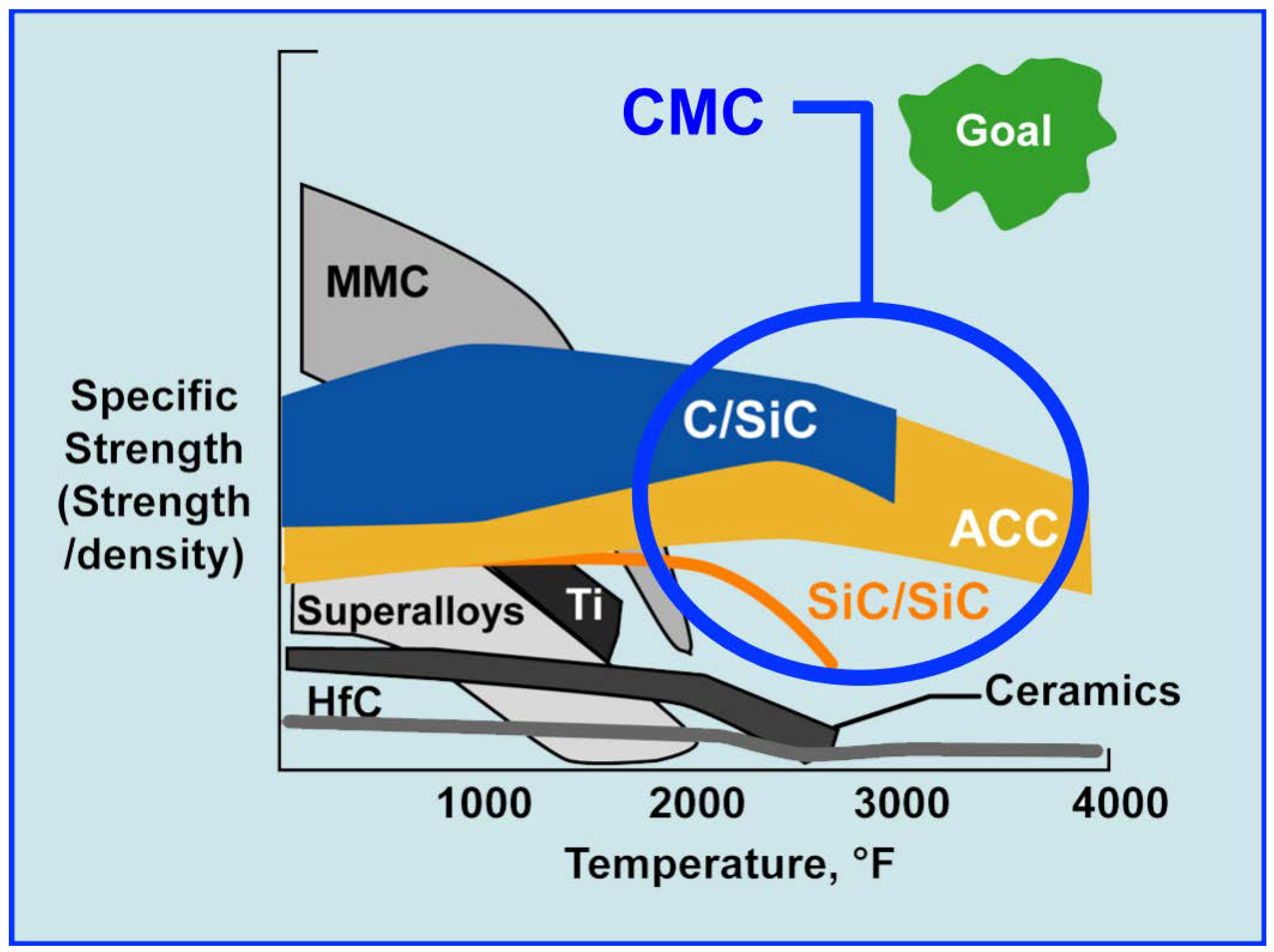
Figure 1. Allowable temperatures of various kinds of high temperature resistance materials [31].
Energies 12 00240 g001
Figure 2. Schematic of the NASA Langley DCSCTF [32].
Energies 12 00240 g002
Figure 3. SEM overview image of the C/C-SiC panel, exposed surface is on the top [33].
Energies 12 00240 g003
Figure 4. C/C-SiC panel mounted as the top wall of the 6 half-angle diverging nozzle [35].
Energies 12 00240 g004
Figure 5. Scanning Electron Microscopy (SEM) and energy spectrum analysis of carbon deposition of part experimental materials [39].
Energies 12 00240 g005
Figure 6. Comparison of nozzle wall temperature predicted by the model and the experimental results [42].
Energies 12 00240 g006
Figure 7. Isothermal cooling effects of all kinds of gases under certain boundary conditions [44].
Energies 12 00240 g007
Figure 8. Schematics of the porous material [45]: (a) a flat plate with blunt leading edge, (b) a two dimensional (2-D) body with blunt leading edge.
Energies 12 00240 g008
Figure 9. Diagram and physical map of the experimental apparatus [47]: (a) Test bench schematic; (b) Air vitiator with attached Mach 2.5 Nozzle.
Energies 12 00240 g009
Figure 10. Microscopic observation of oxidation of the adhesive layers prepared by three spraying methods under certain working conditions [52]: (a) Comparison of the oxide scales formed on 0.6 mm thick freestanding specimens of coating; (b) Results of isothermal oxidation tests of freestanding specimen of HV-APS and LPPS coatings (0.6 mm thickness) at 1100 C in synthetic air for 72 h.
Energies 12 00240 g010
Figure 11. Spectral analysis of microstructure of LPPS coating and HV-APS coating after exposure to air at high temperature [57]: (a) LPPS coating; (b) HV-APS coating.
Energies 12 00240 g011
Figure 12. SEM observation results of cross sections of the cracked APS-flash coatings prepared by different technologies: (a) VPS and (b) HVOF [58].
Energies 12 00240 g012
Figure 13. SEM sectional views of coatings of three structures after the erosion test: (a) classical YSZ structure, (b) t’Low-k structure, and (c) GZO structure [60].
Energies 12 00240 g013
Figure 14. Calculation of thermal conductivity of materials under molecular dynamics simulation [61].
Energies 12 00240 g014
Figure 15. Thermal conductivity of coatings with different Nd 2 O 3 /Yb 2 O 3 concentrations [64].
Energies 12 00240 g015
Figure 16. Microstructural behavior during TCF test for YSZ SPS columnar structure (a) and for YSZ SPS compact columnar structure (b) [70].
Energies 12 00240 g016
Figure 17. TMS Architecture for Cooling Recirculating Fuel with LNG [77].
Energies 12 00240 g017
Figure 18. Schematic diagram of the calculation model of the single cooling channel of ramjet [80].
Energies 12 00240 g018
Figure 19. Schematic diagram of single tube test apparatus [80].
Energies 12 00240 g019
Figure 20. Schematic diagram of fuel cycle scramjet [81].
Energies 12 00240 g020
Figure 21. Schematic diagram of flow rate, temperature at the outlet of cooling channel, and irregular distribution of n-decane [82].
Energies 12 00240 g021
Figure 22. Schematic of experimental setup for thermal cracking of n-dodecane [84].
Energies 12 00240 g022
Figure 23. Contours and secondary flow lines of the axial velocity of flow fields obtained from the SA model and the RSM model [85].
Energies 12 00240 g023
Figure 24. Meshing of meta-analysis of local structure and graphical representation of temperature and pressure distribution [88]: (a) Temperature distribution; (b) stress distribution.
Energies 12 00240 g024
Figure 25. Schematic diagram of SHEDR cycle [93].
Energies 12 00240 g025
Figure 26. Schematic diagram of the ramjet model [95].
Energies 12 00240 g026
Figure 27. Comparison of wall heat flux and temperature of the turbulent flow model and laminar flow model [98].
Energies 12 00240 g027
Figure 28. H 2 O combustion contours along the bottom wall for high-compression, low-compression, fully fueled, and inlet radical suppressed simulations [103].
Energies 12 00240 g028
Figure 29. Schematic diagrams of OH Chemiluminescence (left) and OH Planar Laser-Induced Fluorescence (right) of the combustion chamber of scramjets [106].
Energies 12 00240 g029
Figure 30. Combustor section exploded view depicting modularity of flow path hardware [111].
Energies 12 00240 g030
Figure 31. Grid diagram and thermal strain analysis of wedge sturt modeling [116].
Energies 12 00240 g031
Figure 32. Comparison of experimental (left) and numerical (right) data for the dimensionless surface temperature at the bottom of the strut [117].
Energies 12 00240 g032
Figure 33. Simulated distribution diagrams of fluid flow rate, pressure, and temperature of symmetrical cross section and isometric cross section [119].
Energies 12 00240 g033
Figure 34. Comparison of heat flux before and after mode transition [125].
Energies 12 00240 g034
Figure 35. Schematic diagrams of intake process of the combustion chambers under the two modes [126].
Energies 12 00240 g035
Figure 36. Surfaces of the specimens after the combustion test [128]: (a) Fractured UHTC struture; (b) Fracture surface of the UHTC struture; (c) FGLCS struture; (d) Thermal insulation layer of the FGLCS struture.
Energies 12 00240 g036
Figure 37. Schematic diagram of the sensor to measure the airflow’s angle of attack and velocity [135].
Energies 12 00240 g037
Figure 38. CAD design drawing and experimental physical map of the temperature sensor [137].
Energies 12 00240 g038
Figure 39. Modeling of grid calculation example of the air inlet [150].
Energies 12 00240 g039
Figure 40. MATLAB flow chart of analysis of air inlet flow field [151].
Energies 12 00240 g040
Figure 41. Model diagram and calculation process of the exhaust nozzle [155].
Energies 12 00240 g041
Figure 42. Model diagrams of three nozzles: (a) two-dimensional nozzle, (b) three-dimensional nozzle, and (c) axisymmetric nozzle [157].
Energies 12 00240 g042
Figure 43. Simulation charts of section fluid flow rate and temperature of three nozzles: (a) two-dimensional nozzle, (b) three-dimensional nozzle, and (c) axisymmetric nozzle [157].
Energies 12 00240 g043
Figure 44. Thermodynamic cycle layout of the MR2 aircraft [166].
Energies 12 00240 g044
Figure 45. General cooling circuit for hydrogen [166].
Energies 12 00240 g045
Figure 46. Differences between the calculation model and the practical situation [173]: (a) actual and estimated heat loads from single trial; (b) heat load error averaged over all trials; (c) actual and estimated thermal endurances computed from single trial; (d) thermal endurance error averaged over all trials.
Energies 12 00240 g046
Figure 47. Schematic of a notional dual tank fuel system [176].
Energies 12 00240 g047
Figure 48. (a) Simplified Block Diagram of Draining Tank with Heat Exchanger in Recirculation Loop; (b) Simplified Block Diagram Laser Coolant Recirculation Loop [178].
Energies 12 00240 g048
Figure 49. Flow diagram of coupling analysis [179].
Energies 12 00240 g049
Figure 50. Computational configuration of reaction flow field [185].
Energies 12 00240 g050
Figure 51. The Distributed Embedded Systems Architecture [186].
Energies 12 00240 g051
Figure 52. CAD design of the scramjet inlet (left); photography of the Ultem 9085 three-dimensional printed scramjet model (center); and schematic of the layer orientation for printing (right) [187].
Energies 12 00240 g052
Table 1. Parameters of the C/C-SiC sandwich structure [37].
Notation (mm)
Total thicknessh15
Skin thickness ( 0 / 90 )t1
Core heightc13
Core wall thickness 0 / 90 and ± 45 t c 0.3
Table 2. Parameters of various fuel combinations [76].
CombinationMixture RatioChamber Pressure (PSI)Vacuum Isp (Seconds)
Lox-Hydrogen61000457.0
H2O2-Kerosene71000331.0
N2O4-Hydrazine1.081000348.0
AP-HTPB-Al5.171000312.6
AP-HTPB2.331000224.0
LOX-Kerosene2.331000347.0
LOX-Methane2.771000365.0
LOX-Butane2.21000255.0
LOX-Isopropanol1.71000341.0
LOX-Propane2.551000357.0