Article

Effect of Vertical Metal Plate on Transfer Efficiency of the Wireless Power Transfer System

Department of Instrumental and Electrical Engineering, Xiamen University, Xiamen 361000, China
*
Author to whom correspondence should be addressed.
Energies 2019, 12(19), 3790; https://doi.org/10.3390/en12193790
Submission received: 14 August 2019 / Revised: 20 September 2019 / Accepted: 27 September 2019 / Published: 7 October 2019

Abstract

:
Power transfer efficiency is an important issue in wireless power transfer (WPT). In actual applications, the WPT system may be exposed to a complex electromagnetic environment. The metal which is inevitably or accidentally close to the system will impact the power transfer efficiency. Most previous research has aimed at the effect of the metallic sheet paralleled to the resonant coil. This paper focuses on the effect of the metallic plate perpendicular to the resonant coils. Firstly, based on the theoretical analysis, a simulation model is setup using COMSOL Multiphysics. The efficiencies of the double-coils magnetic resonant WPT system with the presence of the parallel and vertical aluminum plate are studied comparatively. Efficiency improvement is observed with the vertical plate while the reduction appeared with the presence of the parallel plate. The vertical metallic plate has shown a magnetic field shielding effect according to the magnetic field distribution. It can reduce the radial magnetic field and enhance the axial magnetic field. Then, the effects of the position and size of the vertical plate are studied. It is found that the transfer efficiency has a preferable improvement when the vertical aluminum plate with a larger size is placed between the resonant coils and near outer edge of the windings. Finally, the experiment is carried out to verify the effect of the vertical aluminum plate on the WPT system.

1. Introduction

Wireless power transmission (WPT) refers to a class of technologies that transfer electric energy without wires. With the advantages of convenience, being contactless and simplicity of maintenance, it has attracted extensive attention and a wide range of applications, such as battery chargers for electronic devices [1,2,3], medical implants [4,5,6], electric vehicles and trams [7,8,9,10].
WPT technology can be traced back to the 19th century [11,12], and has developed rapidly in the past 10 years. The most important issues of a WPT system are the power transfer efficiency and the power transfer distance. Many attempts such as coil structure optimization [13,14,15], maximum frequency tracking [16,17,18,19], and the multi-coils system [20,21,22] have been developed in order to improve system performance. However, before large-scale practical application, safety concerns also need to be clarified and addressed [23,24,25,26].
In actual applications, the WPT system will generate a leakage magnetic field to the surrounding area. To limit electromagnetic radiation, many schemes including a conductive shield, magnetic shield, designed structure, and additional compensated coils have been proposed [13,27,28,29,30,31]. Among them, a conductive shield is a basic shielding method which uses the reversed magnetic field produced by eddy current in a good conductor to reduce the leakage magnetic field. It is a simple but effective shielding technique, especially at high frequency. Relevant attenuation can be produced with a shield of few millimeters thickness.
Besides the conductive shield, charged devices inevitably contain other metallic components. According to Faraday’s law of electromagnetic induction, the leakage magnetic field will induce an eddy current in these conductive components during the WPT process. Then, Joule heating due to the eddy current causes energy consumption. In addition, the introduction of the metal components will affect the magnetic field distribution. These will influence the power transfer efficiency and degrade the performance of the WPT system.
To improve system performance and reduce the impact on the surroundings, the effect of metallic objects on the WPT system needs to be researched. Many scholars have studied the performance of the system with the presence of metallic obstacles [32,33,34,35,36,37,38]. The research shows that metal obstacles near the system such as the metal enclosure and shielding sheet influence the parameters of the WPT system and result in a deviation of the resonant frequency. Moreover, the eddy current induced in the metal obstacles causes temperature rise and energy consumption. Although methods such as frequency adjustment, impedance matching and structure optimization can diminish the impact of the metal obstacles [35,36,37,38], the system still have lower energy transfer efficiency with the presence of the metal obstacles.
Most of the previous research is aimed at the metallic sheet paralleled to the resonant coils. The metal obstacles perpendicular to the coils are also common and important in the actual application of the WPT system. The effect of these obstacles on the performance of the system also should be studied. In this study, we focus on the non-ferrite metallic obstacles perpendicular to the resonant coils. Firstly, the WPT system efficiencies with and without the metal obstacles are analyzed in theory. Based on the analysis, a simulation model of the WPT system is set up by COMSOL Multiphysics. With this model, we studied the effect of a vertical aluminum plate on the WPT system performance numerically. Then, the variations of the system efficiency caused by the vertical aluminum plates with different positions and sizes are studied in detail. Finally, the WPT experiment is conducted to verify the effect of the vertical metallic plate.

2. Basic Principle and Simulation

2.1. Basic Principle

According to the operation principle, WPT techniques can be divided into three categories: inductive coupling, capacitive coupling and electromagnetic radiation. Inductive coupling is the most widely used WPT technology, and the magnetic resonant WPT is a special inductive coupling system. Herein, the study is based on a double-coil magnetic resonant WPT system with series–series topology. The equivalent circuit of this system is shown in Figure 1. In the system, the energy is transmitted from the power transmitter to the power receiver though the resonant coils. To simplify the analysis, the structure of the receiver coil (RX-coil) here is the same as the transmitter coil (RX-coil). The resonant frequency depends on the resonant coils and the series resonant capacitors. When the source frequency is equal to the resonant frequency, the system has an optimal performance.
Based on the Kirchhoff’s circuit law, the system circuit equations without the presence of the metallic obstacles can be set up.
( R 1 + j ω L 1 + 1 j ω C 1 ) I ˙ 1 + j ω M 12 I ˙ 2 = U ˙
j ω M 12 I ˙ 1 + ( R 2 + R L + j ω L 2 + 1 j ω C 2 ) I ˙ 2 = 0
In the equations, U ˙ is the voltage of the alternating current (AC) source, I ˙ 1 and I ˙ 2 are the current in the transmitter and the receiver, and ω expresses the system resonant frequency. R 1 , L 1 and C 1 are the resistance, inductance and capacitance of the transmitter circuit, respectively. R 2 , L 2 and C 2 are the resistance, inductance and capacitance of the receiver circuit. R L is the load resistance. M 12 expresses the mutual inductance between the transmitter and receiver.
If the fluctuation of the resonant frequency is ignored, we can deduce the system energy efficiency η according to Equations (1) and (2).
η = | I ˙ 2 2 | R L Re ( U ˙ I ¯ 1 ) = ω 2 M 12 2 R L [ R 1 R 2 + ω 2 M 12 2 ] R 2
where R 2 represents R 2 + R L .
However, the metallic obstacles in the vicinity may impact the system performance. According to Faraday’s law of electromagnetic induction, eddy current will be induced in the conductive plate. The transfer energy may be influenced by the induced magnetic field, and will also be partly dissipated due to joule heating in the metallic obstacles. The metallic obstacle can be considered as an added loop that contains a resistor and a inductor. The system circuit equations with the presence of the metallic obstacles can be rewritten as:
( R 1 + j ω L 1 + 1 j ω C 1 ) I ˙ 1 + j ω M 12 I ˙ 2 + j ω M 13 I ˙ 3 = U ˙
j ω M 12 I ˙ 1 + ( R 2 + R L + j ω L 2 + 1 j ω C 2 ) I ˙ 2 + j ω M 23 I ˙ 3 = 0
j ω M 13 I ˙ 1 + j ω M 23 I ˙ 2 + ( R 3 + j ω L 3 ) I ˙ 3 = 0
where I ˙ 3 is the equivalent current in metal plate, R 3 and L 3 are the equivalent resistance and inductance of the metallic plate. M 13 expresses the mutual inductances between the transmitter and metal plate, and M 23 expresses the mutual inductances between the receiver and metal plate.
According to the Equations (4)–(6), the system energy efficiency can be deduced.
η = | I ˙ 2 2 | R L Re ( U ˙ I ¯ 1 ) = ( ω 2 M 12 2 K 1 + K 2 ) R L [ ( R 1 R 2 + ω 2 M 12 2 ) K 1 + K 2 ] R 2 + K 3
In this equation,
K 1 = ω 2 L 3 2 + R 3 2
K 2 = ω 4 M 13 2 M 23 2 2 ω 4 L 3 M 12 M 13 M 23
K 3 = ω 2 M 23 2 ( ω 2 M 23 2 R 1 + ω 2 M 13 2 R 2 + 2 R 1 R 2 R 3 + ω 2 M 12 2 R 3 ) + ω 2 M 13 2 R 2 2 R 3
Divide η by η ,
k = η η = 1 + 2 ω 4 L 3 M 12 M 13 M 23 + ω 2 M 13 2 R 2 R 3 + 2 ω 2 M 23 2 R 1 R 3 + ω 4 M 23 2 ( M 23 2 R 1 + M 12 2 R 3 ) R 2 ( K 1 + K 2 ω 2 M 12 2 ) ( R 1 R 2 + ω 2 M 12 2 )

2.2. Simulation

As stated in Section 1, the previous studies mostly aimed at the metallic obstacles parallel to the coils. There is less research on the effect of the metallic obstacles perpendicular to the coils. In order to analyze the effect of the vertical metallic plate, a 3D simulation model of the WPT system is set up with the multi-field modeling and simulation software COMSOL Multiphysics. In order to simplify simulation and reduce the computation time, we use the multi-turn coil module to simulate the resonant coils. The schematic of the simulation model is shown in Figure 2. TX-coil and RX-coil are concentric and parallel. They are winded by the copper wire and with the same flat spiral structure. They have 12 turns and 1 layer. The inner and outer radii of the resonant coils are 60 mm and 100 mm, respectively. The thicknesses of the coils are both 1 mm. The resonant frequency of the coils is adjusted to 1 MHz with resonant capacitors. The simulation parameters are detailed in Table 1.
In the simulation, free tetrahedral mesher with predefined sets of finer were employed to generate the model mesh. We also subdivided the coil into more finer grids to ensure the simulation precision. We used frequency domain solver to carry out this simulation. The iterative solver GMERS (generalized minimal residual method) was employed to increase the simulation accuracy. The exciting current was introduced to the coil by circuit module with a high-frequency AC source of 40 V. Then the magnetic field distribution and transmission characteristics could be calculated by finite element method based on Maxwell’s equations.

3. Effect of Metallic Plates

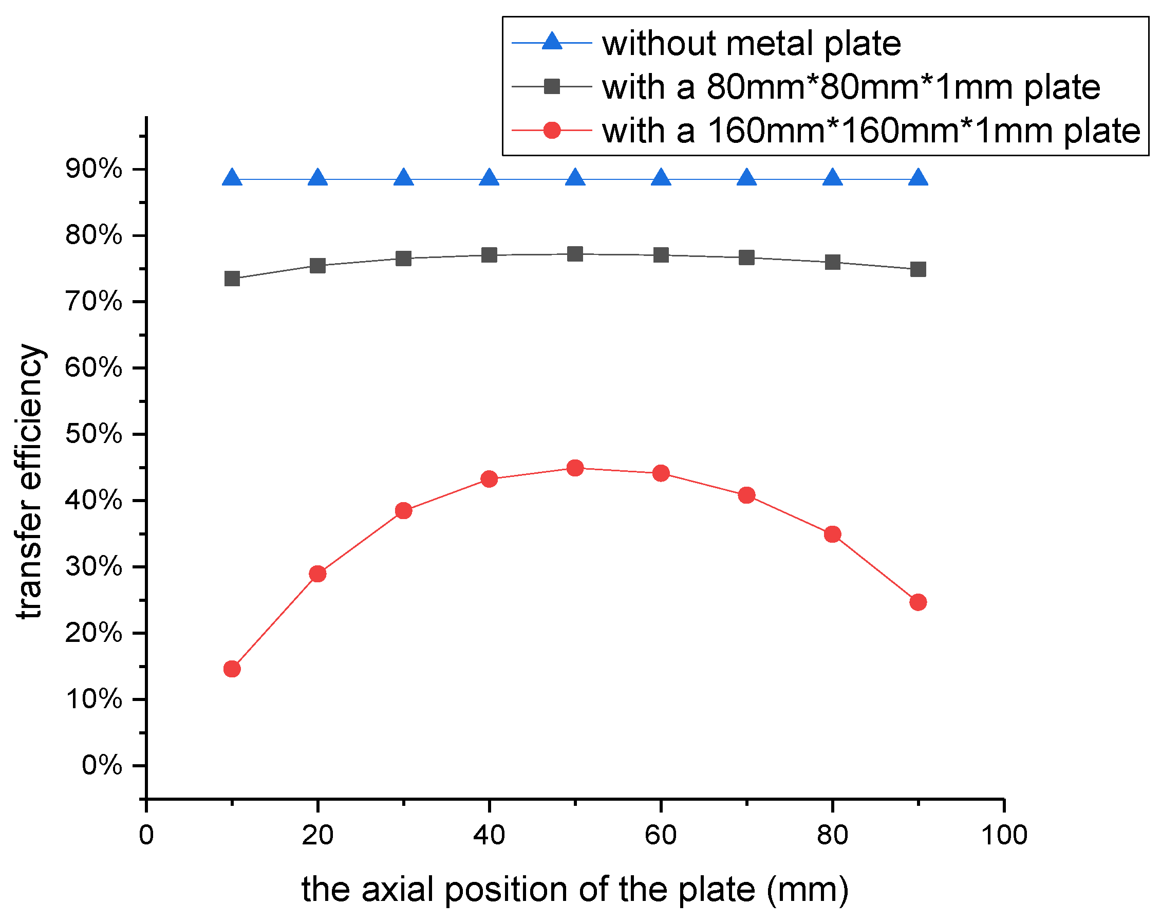
3.1. Impact of Parallel Metal Plates

With the simulation model, the impact of metallic obstacles paralleled to the resonant coils is first studied. According to the permeability, metal can be divided into ferrite metal and non-ferrite metal. Herein, we mainly focus on the non-ferrite metal. The aluminum plate is chosen as the non-ferrite metallic obstacles here.
The transfer efficiency of the WPT system changes with the distance between the resonant coils as the coupling coefficient changes. In this simulation, the system transfer efficiency is 88.44% at 100 mm. When parallel aluminum plates with different sizes are placed between the two resonant coils, the variations of the efficiency with the axial position of the plate are shown in Figure 3. The axial position of the plate represents the distance from the transmitter coil. From the figure, we can see that the efficiency declines with the presence of the parallel aluminum plate. When the plate is closer to one of the resonant coils, the efficiency has a larger decline. When the plate is in the middle of the resonant coils, it has the least effect on efficiency. On the other hand, the efficiency decrease is also related to the size of the aluminum plate. The 160 × 160 × 1 mm plate has a greater impact on the efficiency rather than the 80 × 80 × 1 mm plate.
When the metallic plate is paralleled to resonant coil, it is perpendicular to the main magnetic field of the transmitter coil. The magnetic field induced by eddy current will weaken the main magnetic field. Combined with current direction, the mutual inductances M 12 and M 13 are negative, where the mutual inductance M 23 is positive. In that case, k is larger than 1 according to Equation (8). The system energy efficiency η with the presence of the metal plate is lower than that without the presence of the metal plate.
The larger the plate, the more magnetic flux will pass through the plate. The main magnetic flux may be further weakened. The value of mutual inductances M 13 and M 23 will increase. Moreover, the resistance R 3 also increases with the size of plate. These lead to a larger value of k , and a lower energy-transfer efficiency.

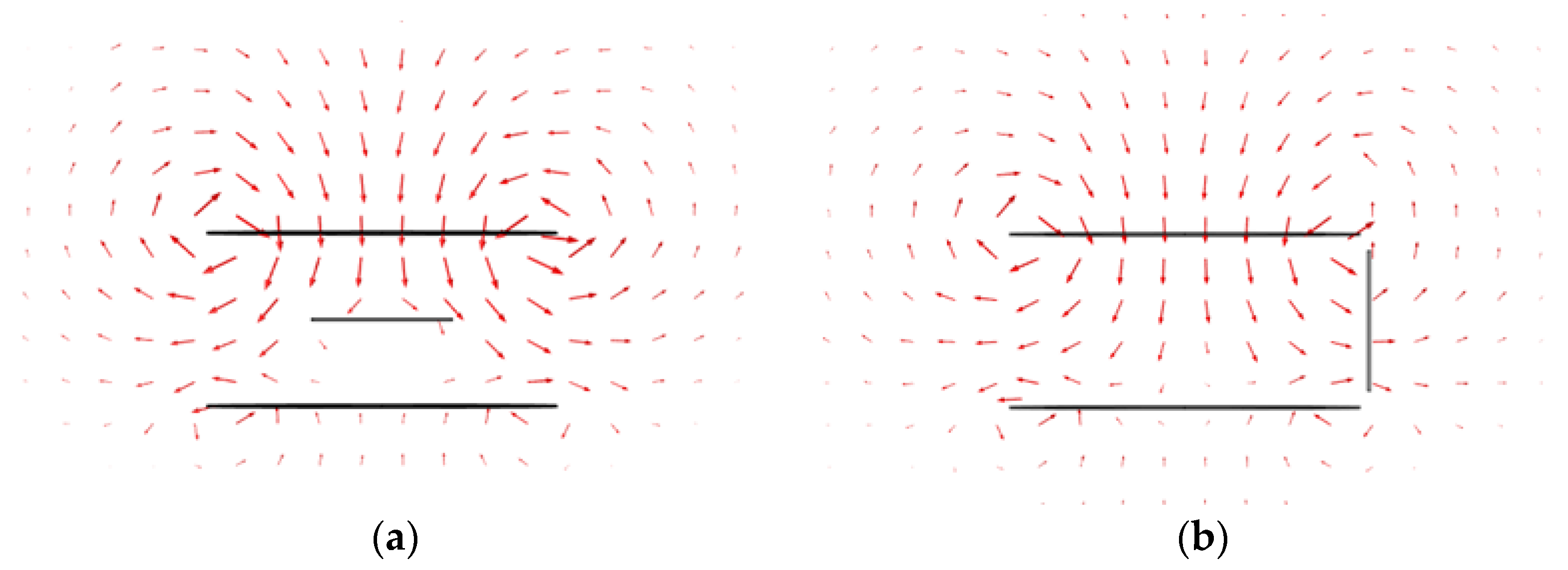
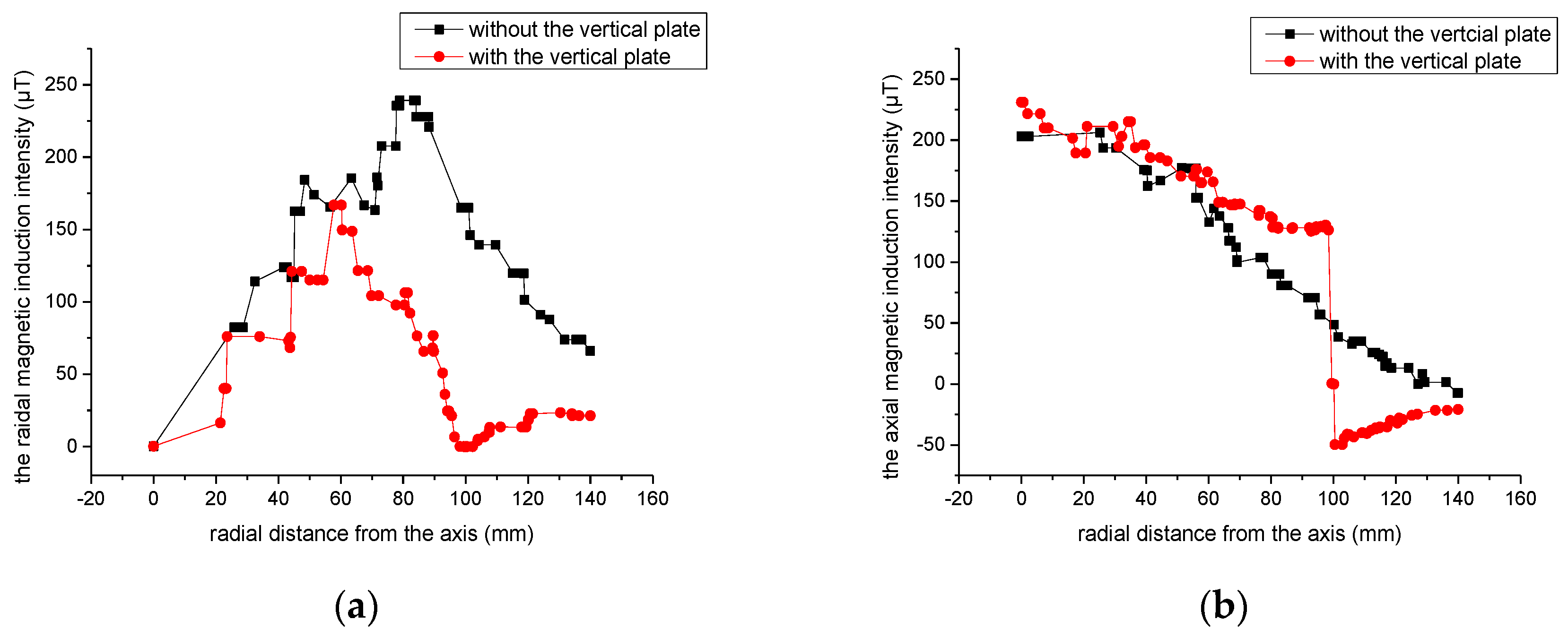
3.2. The Impact of Vertical Metal Obstacles

In the WPT system, vertical metallic obstacles such as a conductive shield or cover may exist in the proximity of the coil, and the impact of them on the system needs to be studied. Herein, the effect of the vertical aluminum plate on the system efficiency is simulated. The arrangement of the vertical plate simulation is shown in Figure 4. In the figure, a vertical aluminum plate with the size of 80 × 80 × 1 mm is placed 100 mm from the common axis and 50 mm from the transmitter coil. It is found that the efficiency of the system is improved from 88.44% to 89.63% with the vertical plate.
In order to clarify the influence mechanism of the vertical aluminum plate, the magnetic field distributions are studied in detail. From Figure 5a, it can be found that the transfer magnetic field between two resonant coils is impeded by the parallel plate. The magnetic field flux intensity behind the aluminum plate is lower than that before the plate. As mentioned above, this results from the reverse magnetic field produced by the eddy current in a conductive plate. Then, the transfer energy and efficiency will be reduced by the reduction of the magnetic field. For the vertical plate, only the leakage magnetic field induced an eddy current in the plate as the plate is parallel to the main magnetic field, as shown in the figure. The induced magnetic field by the eddy current in the vertical plate impedes the leakage of the magnetic field. From Figure 5b, we can find that the magnetic field intensity outside the plate are lower than that inside the plate. The plate shows a shielding effect of the magnetic field. It can reduce the leakage magnetic field and enhance the main magnetic field. This enhancement improves the transfer efficiency of the WPT system.
To verify the enhancement of the magnetic field, the magnetic induction intensity is also studied. We predict the variations of the magnetic induction intensity on the radial direction in Figure 6. Figure 6a shows the changes of radial magnetic induction intensity in the middle plane between the resonant coils with and without the vertical aluminum plate. It can be seen that the vertical plate effectively suppresses the radial magnetic induction intensity near the metallic plate. The changes of axial magnetic induction intensity in the plane 75 mm from the transmitter coil are shown in Figure 6b. We can find that the axial magnetic induction intensity inside the vertical plate is enhanced by the plate. This indicates the main magnetic field of energy transfer is enhanced.
When the vertical metallic plate is perpendicular to the coils, it is paralleled to the main magnetic field. Only leakage flux passes through and induces current in the plate. The induced magnetic field mainly weakens the leakage flux but not the magnetic field. It even enhances the main magnetic field transmission to some extent. In this case, all the mutual inductances M 12 , M 13 and M 23 are negative. It increases the value of K 2 in Equation (7). If the other parameters are properly set, k can be smaller than 1, and the system energy efficiency η with the presence of metal plate will be higher than that without the presence of metal plate.

3.3. Effect of the Radial Position

For further study, the effects of the vertical plate position and size on the performance of the system are analyzed with the simulation model. The distance between the resonant coils remains 100 mm. The variation of the system efficiency on the radial position of the plate is first depicted in Figure 7. From the figure, we can see that the energy-transfer efficiency is changed with the radial position. With the increase of the radial, the transfer efficiency first increases and then decreases. The vertical plate can improve the transfer efficiency when the plate is near the windings of the coils. It reaches a maximum value of 89.88% when the radial distance of the aluminum plate is 80 mm. When the radial distance is less than 20 mm, the transfer efficiency decreases slightly. The plate has nearly no effect on the performance of the system when the radial distance is larger than 140 mm.
This is because the aluminum plate cannot suppress the leakage magnetic field effectively when the plate is too close or too far from the common axis of the coils. Moreover, the induced current causes energy losses from joule heating. Then it results in a slight reduction of the energy transfer efficiency when the radial distance is too small. When the plate is placed near the windings, the radial magnetic induction intensity is relatively large, and it induced higher eddy current density in the plate which can impede most of the leakage magnetic field and result in a larger improvement of energy transfer efficiency.

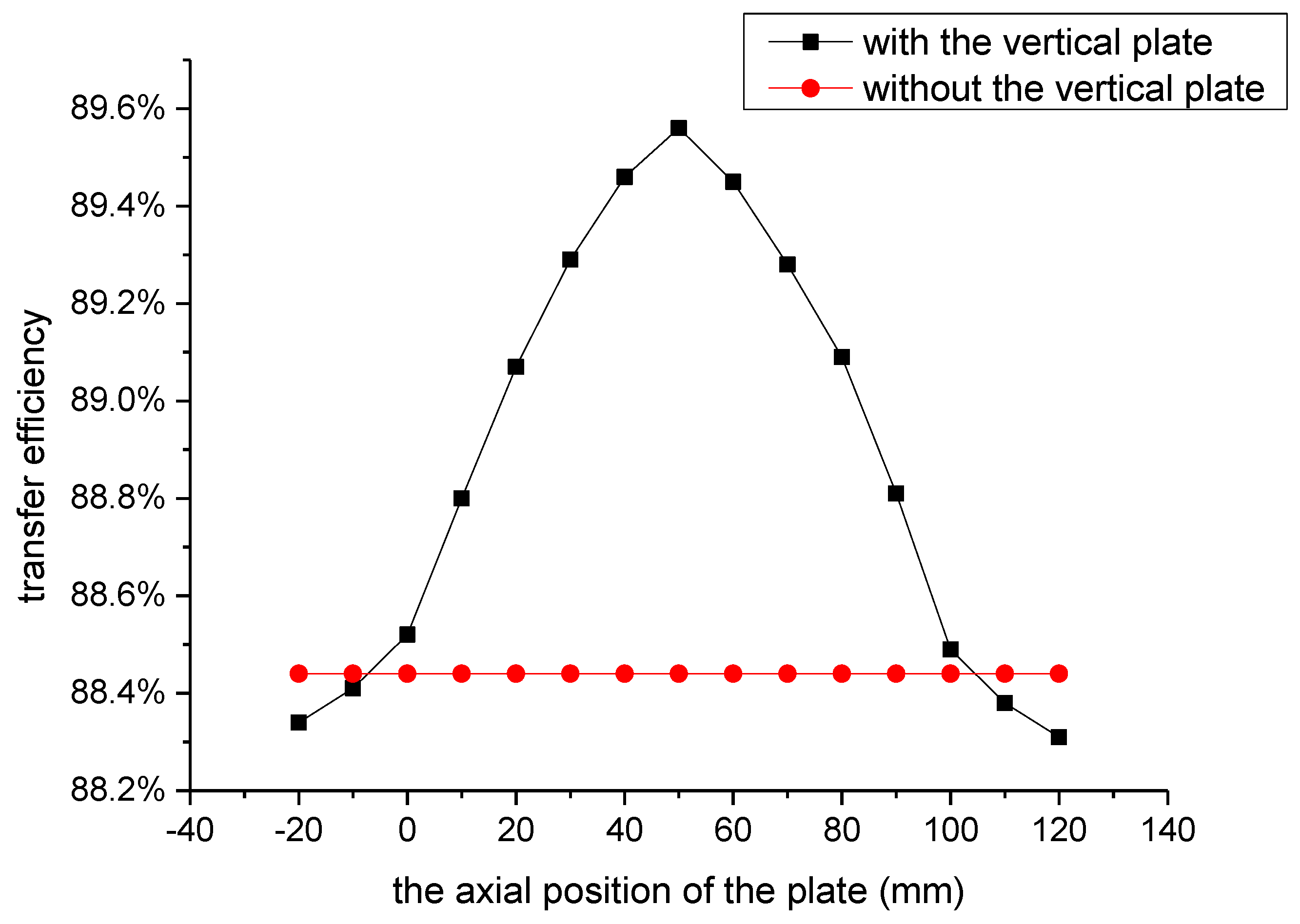
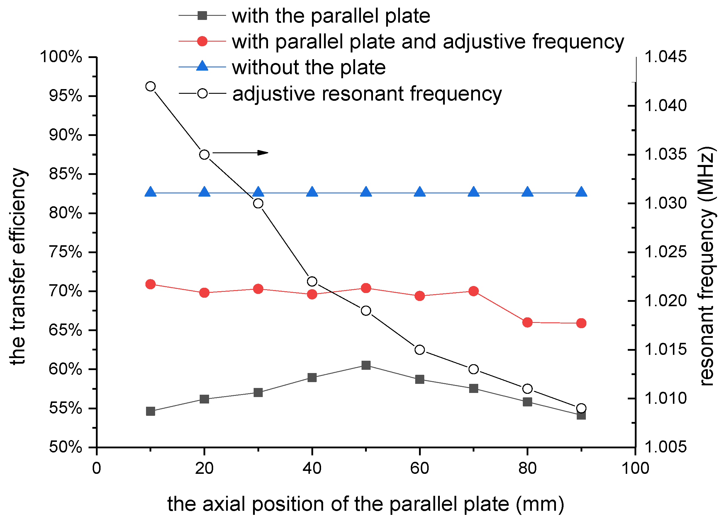
3.4. Effect of the Axial Position
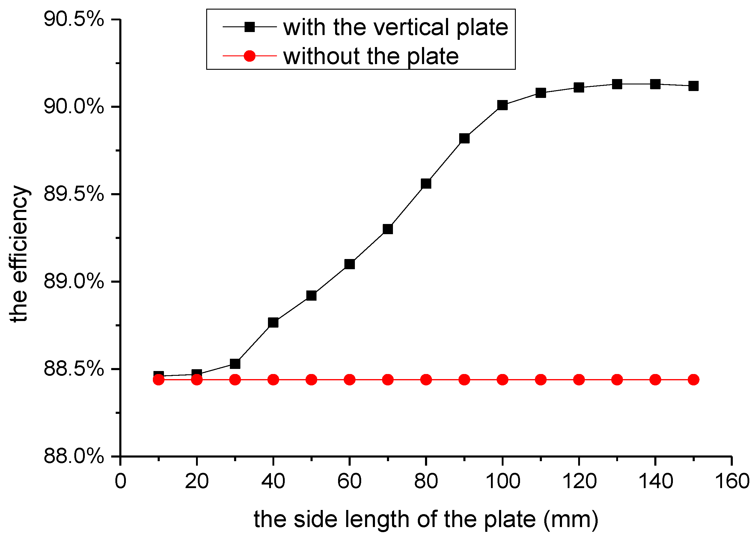
The axial position of the vertical plate also affects the transfer efficiency. Combined with the effect of the radial position and the feasibility of the axial movement, the vertical plate is placed near the outer edge of the resonant coil and 105 mm from the common axis. The variation of the efficiency with the axial position is shown in Figure 8. In the figure, the distance between the center of the vertical plate and the transmitter resonant plane is used to indicate the axial position of the vertical plate. We can find that the efficiency is improved when the axial position is ranged from 0 mm to 100 mm. The largest efficiency of 89.56% occurs when the axial distance is about 50 mm while the center of the plate is in the middle of the two coils. When the center of the plate is close to the transmitter or receiver coil, the efficiency decreases. The reduction is mainly caused by the increase of the joule heating and the decrease of the shielding effect.

3.5. Effect of Size

We also study the effect of the plate size. Square aluminum plates with the thickness of 1 mm are employed in this simulation. The radial and axial positions of the vertical plate are 105 mm and 50 mm from the center of the resonant coils. The transfer efficiencies with the presence of the aluminum plates with different side lengths are depicted in Figure 9. The results show that the vertical plates can enhance the transfer efficiency. The improvement increases with the side length. When the side length is shorter than 30 mm, there is no obvious improvement due to the combined action of shielding and joule heating. When the side length is larger than 100 mm, the increase of the side length has less impact on the improvement of the efficiency.

4. Experiment Results

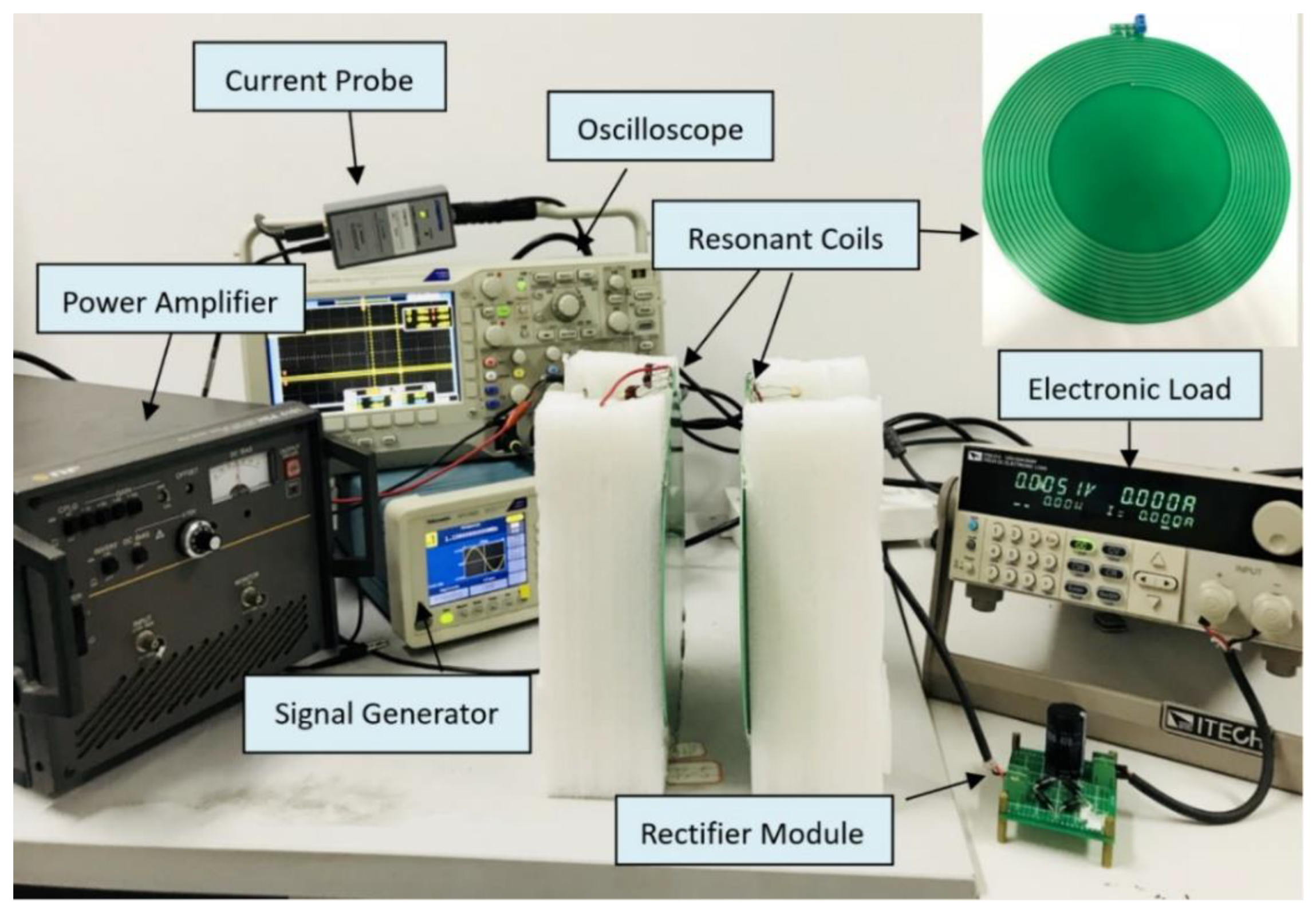
4.1. Experimental Setup

Based on the simulation, an experimental system is set up to verify the effect of the vertical aluminum plate on the transfer efficiency. The system includes high-frequency power supply, resonant coils, resonant circuit, rectifier circuit and the electronic load as shown in Figure 10. The resonant coils are produced with the printed circuit board (PCB) technology with a similar size as the simulation model. They have 12 turns with the inner and outer diameter of 120 mm and 200 mm. The width of the copper wire is 2.50 mm, respectively. The turn spacing of the windings is 1 mm. However, the thickness of the PCB coils in this experiment is different from that of the simulation. The resonant capacitance is 670 pF, and the resonant frequency of the system is about 1 MHz. During the experiment, the load is set as 100 Ω.

4.2. Experimental Results

The effect of the aluminum plate parallel to the resonant coil is first studied. The distance between the two resonant coils is set as 100 mm. The efficiency of the experiment system (82.6%) is lower than that in the simulation (88.44%). It is probably caused by the circuit resistance of the circuit and the loss in rectifier module which are ignored in the simulation. On the other hand, the thinner PCB coils in the experiment also leads to a difference. However, the skin depth of copper at the frequency of 1 MHz is about 0.07 mm, so the efficiency reduction caused by the different thickness can be neglected.
An aluminum plate with the size of 80 × 80 × 1 mm is employed in the experiment. The transfer efficiencies with the parallel plate at different axial positions are present in Figure 11. The variation trend is similar to that in the simulated analysis. The parallel aluminum plate decreases the transfer efficiency. The effect is least when the plate is in the middle of the resonant coils and largest when the plate is near the resonant coils. In the experiment, we also find the parallel plate will influence the resonant frequency of the system. The variation of the resonant frequency with the parallel plate at different axial position and the efficiency with the adjusted resonant frequency are also depicted in Figure 11. The results show that the resonant frequency with the parallel plate is higher than that without the parallel plate. The increase decreases with the distance of the plate from the transmitter coil. The system transfer efficiency can be improved by adjusting the resonant frequency. However, the adjusted efficiency is still lower than that without the parallel plate.
The effect of the aluminum plate perpendicular to the resonant coil is then studied. We conducted the experiment with different radial and axial positions. Firstly, the axial position of plate is kept at 50 mm, and the experimental results of the variation with different radial position are show in Figure 12. The transfer efficiency decreases slightly when the radial distance from the common axis is less than 30 mm. It is enhanced when the radial distance is larger than 40mm. The largest efficiency improvement of 4.42% occurred when the radial distance was about 90 mm. The variation tendency with the different radial position is in accordance with the simulation. In addition, the vertical plate has no effect on the resonant frequency of the system.
Then the radial position of the plate was kept at 105 mm, and the experiment results of the efficiency variation with the axial position are shown in Figure 13. When the axial distance between the center of the plate and the transmitter coil was from 10 mm to 80 mm, the vertical plate improves the transfer efficiency. The efficiency has a maximum value of 85.7% when the center of the vertical plate is 50 mm from the plane of the transmitter coil. However, the efficiency will decrease when the vertical plate is close to one of the resonant coils. The variation tendency of the experimental results is also in agreement with those in the simulation.
Moreover, to further improve the transfer efficiency, the experiment with four vertical plates is also carried out in this study. In the experimental arrangement, the four aluminum plates are placed symmetrically around the resonant coils. The radial positions of them are all kept at 105 mm. The transfer efficiencies are measured at different axial positions. The results are shown in Figure 14. From the figure, we can find that the maximum efficiency was achieved when the plates are in the middle of the resonant coils. In this case, the efficiency was improved by 8% and reaches 89.2%.

5. Conclusions

This paper studied the effect of the vertical metallic plate on the efficiency of the WPT system. With the simulation model, it is found that the vertical plate between the resonant coils can improve the energy transfer efficiency while the parallel plate reduces the transfer efficiency. The analysis of the magnetic field distribution shows that the vertical plate can effectively suppress the leakage magnetic field and enhance the main magnetic field. It can improve the efficiency of the system with the shielding effect. The position and size of the plate will affect the shielding effect. In this study, the transfer efficiency has a preferable improvement when the vertical aluminum plate with a larger size is placed between the resonant coils and near the windings. An experimental system according to the simulation model was also carried out. The results verified that the employment of the vertical aluminum plate can improve the system efficiency at the proper position without resonant frequency shift. Moreover, it also showed that the four vertical plates can further improve the energy transfer efficiency. This may have significance for the design and improvement of the WPT system. The mechanism and quantitative calculation of the effect of a vertical metal plate on transfer efficiency will be further researched in our following study.

Author Contributions

Conceptualization, writing—review and editing, L.H.; methodology and writing—original draft preparation, J.Z. (Jiahao Zou); formal analysis and data curation, Y.Z.; simulation, J.Z. (Jing Zhang); experiments, Y.H. and Z.D.

Funding

This research was supported in part by the National Natural Science Foundation of China (no. 51607152) and the Presidential Fund of the Xiamen University (no. 20720180079).

Conflicts of Interest

The authors declare no conflict of interest.

References

  1. Kuipers, J.; Bruning, H.; Bakker, S.; Rijnaarts, H. Near field resonant inductive coupling to power electronic devices dispersed in water. Sens. Actuators A Phys. 2012, 178, 217–222. [Google Scholar] [CrossRef]
  2. Kim, J.; Son, H.; Kim, D.; Park, Y. Optimal design of a wireless power transfer system with multiple self-resonators for an LED TV. IEEE Trans. Consum. Electron. 2012, 58, 775–780. [Google Scholar] [CrossRef]
  3. Wei, X.; Wang, Z.; Dai, H. A critical review of wireless power transfer via strongly coupled magnetic resonances. Energies 2014, 7, 4316–4341. [Google Scholar] [CrossRef]
  4. RamRakhyani, A.; Mirabbasi, S.; Chiao, M. Design and optimization of resonance-based efficient wireless power delivery systems for biomedical implants. IEEE Trans. Biomed. Circuits Syst. 2010, 5, 48–63. [Google Scholar] [CrossRef] [PubMed]
  5. Kim, S.; Ho, J.; Chen, L.; Poon, A. Wireless power transfer to a cardiac implant. Appl. Phys. Lett. 2012, 101, 073701. [Google Scholar] [CrossRef] [Green Version]
  6. Agarwal, K.; Jegadeesan, R.; Guo, Y.; Thakor, N. Wireless power transfer strategies for implantable bioelectronics. IEEE Rev. Biomed. Eng. 2017, 10, 136–161. [Google Scholar] [CrossRef] [PubMed]
  7. Kalwar, K.; Aamir, M.; Mekhilef, S. Inductively coupled power transfer (ICPT) for electric vehicle charging—A review. Renew. Sustain. Energy Rev. 2015, 47, 462–475. [Google Scholar] [CrossRef]
  8. Li, Z.; Zhu, C.; Jiang, J.; Song, K.; Wei, G. A 3-kW wireless power transfer system for sightseeing car supercapacitor charge. IEEE T Power Electr. 2017, 32, 3301–3316. [Google Scholar] [CrossRef]
  9. Bi, Z.; Kan, T.; Mi, C.; Zhang, C.; Zhao, Z.; Keoleian, G. A review of wireless power transfer for electric vehicles: Prospects to enhance sustainable mobility. Appl. Energy 2016, 179, 413–425. [Google Scholar] [CrossRef] [Green Version]
  10. Choi, S.; Gu, B.; Jeong, S.; Chun, T. Advances in wireless power transfer systems for roadway-powered electric vehicles. IEEE J. Emerg. Sel. Top. Power Electron. 2014, 3, 18–36. [Google Scholar] [CrossRef]
  11. Tesla, N. Apparatus for Transmission of Electrical Energy. U.S. Patent 649,621, 15 May 1990. [Google Scholar]
  12. Tesla, N. Apparatus for Transmitting Electrical Energy. U.S. Patent 1,119,732, 1 December 1914. [Google Scholar]
  13. Kim, H.; Song, C.; Kim, D.H.; Jung, D.H.; Kim, I.M.; Kim, Y.I.; Kim, J.; Ahn, S.; Kim, J. Coil design and measurements of automotive magnetic resonant wireless charging system for high-efficiency and low magnetic field leakage. Trans. Microw. Theory Tech. 2016, 64, 383–400. [Google Scholar] [CrossRef]
  14. Kang, M.; Noh, E.; Kim, K. NFC transmitter coil placement to minimise degradation of A4WP wireless power transfer efficiency. Electron. Lett. 2017, 53, 616–618. [Google Scholar] [CrossRef]
  15. Wang, S.; Chen, J.; Hu, Z.; Rong, C.; Liu, M. Optimisation design for series–series dynamic WPT system maintaining stable transfer power. IET Power Electron. 2017, 10, 987–995. [Google Scholar] [CrossRef]
  16. Feng, H.; Cai, T.; Duan, S.; Zhao, J.; Zhang, X.; Chen, C. An LCC-compensated resonant converter optimized for robust reaction to large coupling variation in dynamic wireless power transfer. IEEE T Ind. Electron. 2016, 63, 6591–6601. [Google Scholar] [CrossRef]
  17. Park, J.; Tak, Y.; Kim, Y.; Kim, Y.; Nam, S. Investigation of adaptive matching methods for near-field wireless power transfer. IEEE Trans. Antennas Propag. 2011, 59, 1769–1773. [Google Scholar] [CrossRef]
  18. Lim, Y.; Tang, H.; Lim, S.; Park, J. An adaptive impedance-matching network based on a novel capacitor matrix for wireless power transfer. IEEE Trans. Power Electron. 2014, 29, 4403–4413. [Google Scholar] [CrossRef]
  19. Fu, M.; Ma, C.; Zhu, X. A cascaded boost-buck converter for high efficiency wireless power transfer systems. IEEE Trans. Ind. Inf. 2014, 10, 1972–1980. [Google Scholar] [CrossRef]
  20. Fei, Z.; Hackworth, S.A.; Weinong, F.; Chengliu, L.; Zhihong, M.; Mingui, S. Relay effect of wireless power transfer using strongly coupled magnetic resonances. IEEE Trans. Magn. 2011, 47, 1478–1481. [Google Scholar] [CrossRef]
  21. Ye, Z.; Sun, Y.; Dai, X.; Tang, C.; Wang, Z.; Su, Y. Energy efficiency analysis of U-coil wireless power transfer system. IEEE Trans. Power Electr. 2015, 31, 4809–4817. [Google Scholar] [CrossRef]
  22. Sampath, J.; Vilathgamuwa, D.; Alphones, A. Efficiency enhancement for dynamic wireless power transfer system with segmented transmitter array. IEEE Tran. Transp. Electr. 2015, 2, 76–85. [Google Scholar] [CrossRef]
  23. Dai, H.; Liu, Y.; Chen, G.; Wu, X.; He, T.; Liu, A.; Ma, H. Safe charging for wireless power transfer. IEEEACM Trans. Netw. 2017, 25, 3531–3544. [Google Scholar] [CrossRef]
  24. Jawad, A.; Nordin, R.; Gharghan, S.; Jawad, H.; Ismail, M. Opportunities and challenges for near-field wireless power transfer: A review. Energies 2017, 10, 1022. [Google Scholar] [CrossRef]
  25. Hui, S.; Zhong, W.; Lee, C. A critical review of recent progress in mid-range wireless power transfer. IEEE Trans. Power Electr. 2013, 29, 4500–4511. [Google Scholar] [CrossRef]
  26. Sun, L.; Ma, D.; Tang, H. A review of recent trends in wireless power transfer technology and its applications in electric vehicle wireless charging. Renew Sustain. Energy Rev. 2018, 91, 490–503. [Google Scholar] [CrossRef]
  27. Feliziani, M.; Cruciani, S. Mitigation of the magnetic field generated by a wireless power transfer (WPT) system without reducing the WPT efficiency. In Proceedings of the 2013 International Symposium on Electromagnetic Compatibility, Brugge, Belgium, 2–6 September 2013; pp. 610–615. [Google Scholar]
  28. Kim, J.; Kim, J.; Kong, S.; Kim, H.; Suh, I.; Suh, N.; Cho, D.; Kim, J.; Ahn, S. Coil design and shielding methods for a magnetic resonant wireless power transfer system. Proc. IEEE 2013, 101, 1332–1342. [Google Scholar] [CrossRef]
  29. Strauch, L.; Pavlin, M.; Bregar, V.B. Optimization, design, and modeling of ferrite core geometry for inductive wireless power transfer. Int. J. Appl. Electrom. 2015, 49, 145–155. [Google Scholar] [CrossRef] [Green Version]
  30. Hu, C.; Sun, Y.; Wang, Z.; Tang, C.; Xiong, Q. Design of magnetic coupler for EVs’ wireless charging. Int. J. Appl. Electrom. 2013, 43, 195–205. [Google Scholar] [CrossRef]
  31. Kim, M.; Kim, H.; Kim, D.; Jeong, Y.; Park, H.; Ahn, S. A three-phase wireless-power-transfer system for online electric vehicles with reduction of leakage magnetic fields. IEEE Trans. Microw. Theory Tech. 2015, 63, 3806–3813. [Google Scholar] [CrossRef]
  32. Zhang, P.; Yang, Q.; Zhang, X.; Li, Y. Comparative study of metal obstacle variations in disturbing wireless power transmission system. IEEE Trans. Mag. 2017, 53, 1–4. [Google Scholar] [CrossRef]
  33. Krishnan, S.; Bhuyan, S.; Kyaw, O.; Kumar, V.P.; Wang, W.J. Effect of proximal metallic objects on the performance of wireless charging systems for electric vehicles. In Proceedings of the 2012 IEEE International Symposium on Radio-Frequency Integration Technology, Singapore, 21–23 November 2012; pp. 128–130. [Google Scholar] [CrossRef]
  34. Wen, F.; Huang, X. Optimal magnetic field shielding method by metallic sheets in wireless power transfer system. Energies 2016, 9, 733. [Google Scholar] [CrossRef]
  35. Ogawa, K.; Oodachi, N.; Obayashi, S.; Shoki, H. A study of efficiency improvement of wireless power transfer by impedance matching. In Proceedings of the 2012 IEEE MTT-S International Microwave Workshop Series on Innovative Wireless Power Transmission: Technologies, Systems, and Applications, Kyoto, Japan, 10–11 May 2012; pp. 155–157. [Google Scholar] [CrossRef]
  36. Liu, G.; Mrad, N.; Xiao, G.; Li, Z.; Ban, D. Metallic environmental effect on RF-based energy transmission. IEEE Antennas Wirel. Propag. Lett. 2012, 11, 925–928. [Google Scholar] [CrossRef]
  37. Yu, X.; Sandhu, S.; Beiker, S.; Sassoon, R.; Fan, S. Wireless energy transfer with the presence of metallic planes. Appl. Phys. Lett. 2011, 99, 214102. [Google Scholar] [CrossRef] [Green Version]
  38. Yu, X.; Skauli, T.; Skauli, B.; Sandhu, S.; Catrysse, P.B.; Fan, S. Wireless power transfer in the presence of metallic plates: Experimental results. AIP Adv. 2013, 3, 062102. [Google Scholar] [CrossRef]
Figure 1. The equivalent circuit of the wireless power transmission (WPT) system.
Energies 12 03790 g001
Figure 2. Schematic of simulation model. (The solver domain is larger than that shown in the figure).
Energies 12 03790 g002
Figure 3. The variations of the efficiency with the position of the plate.
Energies 12 03790 g003
Figure 4. The arrangement of the vertical plate simulation.
Energies 12 03790 g004
Figure 5. The distribution of the magnetic field; (a) with the parallel plate; (b) with the vertical plate.
Energies 12 03790 g005
Figure 6. The variation of the magnetic induction intensity in the radial direction. (a) the radial magnetic induction intensity in the plane 50 mm from the transmitter coils; (b) the axial magnetic induction intensity in the plane 75 mm from the transmitter coils.
Energies 12 03790 g006
Figure 7. The variations of the system efficiency on the radial position of the vertical plate.
Energies 12 03790 g007
Figure 8. The variation of the system efficiency with the radial distance of the vertical plate.
Energies 12 03790 g008
Figure 9. The variation of the system efficiency with the size of the vertical plate.
Energies 12 03790 g009
Figure 10. The arrangement of the experimental system.
Energies 12 03790 g010
Figure 11. Experimental results of the variation of the efficiency with the axial position of the parallel plates.
Energies 12 03790 g011
Figure 12. Experimental results of the variation of the efficiency with the radial position of the vertical plates.
Energies 12 03790 g012
Figure 13. Experimental results of the variation of the efficiency with the axial position of the vertical plates.
Energies 12 03790 g013
Figure 14. Experimental results of the variation of the efficiency with the axial position of the system with four vertical plates.
Energies 12 03790 g014
Table 1. The detailed parameters of the simulation.
ParameterDescriptionValue
NTurns of coils12
R0Inner radius of coils60 mm
R1Outer radius of coils100 mm
DDistance between the coils100 mm
SCross-section area of wire0.14 mm2
RLLoad resistance 100 Ω
LInductance of coil32.19 μH
CCompensation capacitor0.787 nF
UVoltage amplitude of alternating current source40 V
fFrequency of AC source1 MHz

