Abstract
Different from the traditional method of the interior permanent magnet synchronous motor (IPMSM), the sensorless maximum torque per ampere (MTPA) control scheme in this paper does not need two observers for rotor position and d-q axis inductances, respectively. It only needs an adaptive sliding mode observer (ASMO) based on the extended flux (EF) to realize double-loop control and MTPA operation simultaneously. The adaptive mechanism of rotor speed is designed to ensure stability of the ASMO. The rotor position and the difference between d-axis and q-axis inductances are obtained from the estimated EF to acquire the MTPA points when the position sensor of the IPMSM is absent. The proposed scheme is realized on a 20kW IPMSM where the sensorless control performance and the MTPA control performance are tested. The effectiveness of the proposed method is verified by the experiment results.
1. Introduction
The Interior Permanent Magnet Synchronous Motor (IPMSM) is extensively used in broad-scale ship electric propulsion and rail transit traction systems [1]. The control of the IPMSM relies on rotor position information. Generally, to obtain the rotor position information, it is necessary to install a mechanical position sensor such as a photoelectric encoder or a resolver on the motor. As a consequence, not only the power density of the motor is reduced but also the operating reliability of the drive system is deteriorated under extreme temperature and electromagnetic noise [2].
The sensorless control technology, that is, the rotor position information, is extracted from the real-time phase currents of the motor instead of the position sensor. The advantage is it can reduce the system volume, lower the maintenance cost and assure the reliable operation at the same time. For this reason, the sensorless control technology has been widely researched [3,4]. At present, the sensorless control for the IPMSM can be divided into two categories: one uses the salient characteristics of motors [5,6], and the other is based on the fundamental model of the motors [7,8,9]. The latter is often adopted for the IPMSM in the middle-speed and high-speed operations, i.e., the back electromotive force-based or the flux-based mathematical model is used to design the corresponding observer estimating the rotor position of the motor. The common observers mainly include model reference adaptive observer [7], sliding mode observer [8] and extended Kalman filter [9]. Among them, Sliding Mode Observer (SMO) has received extensive attention due to its strong robustness and fast convergence speed [7]. The original fundamental model of the IPMSM is highly nonlinear and strong-coupling, so the corresponding observer structure might be complex to estimate the rotor position and speed. To solve this problem, the Extended Back Electromotive Force (EEMF) is proposed in [10], which linearizes the motor model so that the rotor position information exists only in the EEMF. In [11], based on the EEMF, the Extended Flux (EF) is further proposed, with which the fundamental model of the IPMSM in two-phase stationary coordinates is decoupled completely. However, since the rotor position information exists in the differential term of EF, the application of the integrator is inevitable. Therefore, the rotor position observer based on EF has the problem of DC drift or phase delay generally [12].
For the IPMSM in industrial applications, maximum torque per ampere (MTPA) control is extensively used to make full use of the reluctance torque and reduce the copper loss of the motor greatly [13]. The key of MTPA control is to obtain the MTPA point. At present, the common methods mainly included formula calculation method [14], look-up table method [15], curve fitting method [16], search algorithm [17] and high-frequency signal injection method [18]. Among them, the formula calculation method with motor parameters is extensively used because of its simple process. However, motor parameters have a variation due to magnetic saturation, cross-coupling and temperature changes, and thereby there is a large deviation in the MTPA points obtained by the formula calculation method. Commonly, to get a more accurate MTPA point when the position sensor of the IPMSM is absent, it is often necessary to increase the order of the observer or add another observer so that the motor parameters can be identified online [19].
By analyzing the fundamental model of the IPMSM based on EF, a sensorless-MTPA scheme of the IPMSM is proposed in this paper. It does not need two observers to estimate the rotor position and the d-q axis inductances respectively, but only rely on an adaptive sliding mode observer (ASMO) to obtain the rotor speed and position. At the same time, the difference between the d-axis and q-axis inductances is obtained from the estimated EF to acquire the MTPA points directly.
2. MTPA Control without Position Sensor
2.1. The Design of ASMO Based on EF
In the two-phase synchronous rotating reference frame, the mathematical model of the interior permanent magnet synchronous motor (IPMSM) based on the EF can be described as [11]
where uα, uβ, iα, iβ are the stator voltages and currents on the axis respectively, Rs is the stator resistance, and are the components of the extended flux (EF) on the axis respectively and , , is the electrical angle of the motor rotor, is the amplitude of EF and , is the amplitude of the permanent magnet flux linkage, Ld and Lq are the d-axis and q-axis inductances respectively, id is the d-axis current.
It can be seen from (1) that the rotor position information exists in the differential terms of and . Therefore, the differential terms can be identified as a whole. To design SMO to observed /dt and d/dt, (1) is expressed to the state equation of current as follows.
To observe the values of d/dt and d/dt, SMO can be designed as
where and are the estimated values of α-β axis stator currents respectively, uα and uβ are the inputs to the observer, and are the outputs of the observer.
Make the difference between (2) and (3), so the error equation can be obtained as
where and .
The estimation errors of stator currents are chosen as the sliding surface of SMO, that is
where S represents the sliding surface, and are components of S on the axis, respectively.
The hyperbolic tangent function tanh(s) is chosen as the control function and its expression is as follows:
Based on the control function above, the control rate of SMO is designed as
where l > 0 is the control law coefficient of the SMO.
When the observer reaches the sliding surface, that is, iα_error = 0 and iβ_error = 0, the observer will stay on the sliding surface. According to the equivalent principle of sliding mode control, the control variables at this time can be regarded as the equivalent control one [11], which can be expressed as
where [ ]Teq is the equivalent control variables of [ ]T.
According to the sliding mode control theory, to make the sliding motion exist and stable, that is, when t tends to infinity, the sliding surface S tends to zero and satisfies S(dS/dt) < 0. According to Lyapunov stability theorem, the Lyapunov function is selected as
The stability condition of the SMO is as follows
By substituting (2) to (7) into (10), the stability condition can be expressed as
To ensure that the above equation is true, the condition should be satisfied as
Therefore, when the value of sliding mode gain l is large enough, the existence of sliding motion can be guaranteed, and the system is asymptotically stable.
In summary, the structure block diagram of SMO based on EF is shown in Figure 1.
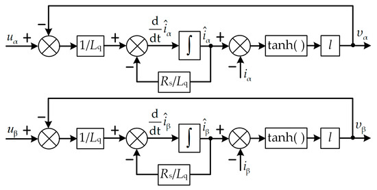
Figure 1.
Structure block diagram of Sliding Mode Observer (SMO) based on extended flux (EF).
Due to the discontinuous switching characteristics of the SMO [8], there are many high-order harmonics in the observed and . To solve this problem, an adaptive mechanism is adopted to construct an ASMO, and the stability of the designed observer is ensured by the adaptive law of estimated speed. As a consequence, it is possible to obtain the equivalent control variables of and without low-pass filters [20].
It can be seen from (8) that and represent the equivalent control variables of d/dt and d/dt respectively. Define = d/dt and = d/dt when the motor operates at steady state, so (13) can be obtained [21].
where is the electrical angular velocity.
With and regarded as the constants in one control period, derive (13) and simplify its result, so (14) can be obtained as
According to (14), the adaptive mechanism of ASMO is designed as
where and are the estimated values of and with the adaptive mechanism respectively, k > 0 is the scale factor of the adaptive mechanism. For the adaptive mechanism, and are the inputs while and are the outputs. Select the state variables as
Then, the equilibrium state of the adaptive mechanism can be expressed as
To analyze the stability of the adaptive mechanism shown in (17), define the Lyapunov function as
The uniform asymptotic stability of the designed adaptive mechanism, that is, to ensure the stability of the adaptive mechanism in the equilibrium state and the state trajectory x(t), starting from any initial state x0 and close to the equilibrium state sufficiently, could converge to the equilibrium state when . In other words, for two given real numbers and , there always exists a real number >0 correspondingly, so that the state trajectory x(t), satisfying the inequality and starting from any initial state x0, meets for any . And the designed Lyapunov function V needs to satisfy the following three conditions:
- In some domain of equilibrium state , scalar function V has continuous first-order partial derivatives.
- In the equilibrium state , i.e., = , = and = , the scalar function V = 0 while the scalar function V > 0 in the non-equilibrium state, i.e., , and .
- In the equilibrium state , i.e., = , = and = , the differential dV/dt = 0 while dV/dt<0 in the non-equilibrium state, i.e., , and .
As can be seen from (18), the constructed Lyapunov function V satisfies conditions I and II, that is, the function V satisfies the sufficient conditions to determine the uniformly asymptotic stability of the nonlinear adaptive mechanism system. With (14) and (15) substituted into (18), the dV/dt can be obtained as
Since k > 0, the first term of the right side in (19) is always negative. Therefore, it can be ensured that dV/dt is negative definite as long as the sum of the remaining items at the right side of (19) is zero. That is
(20) is the estimated speed adaptation law to ensure uniform asymptotic stability of the adaptive mechanism. To improve the dynamic performance of the adaptive mechanism, (20) can be corrected to [22]
where Kp and Ki are the coefficients of the adaptive law.
The block diagram of ASMO based on EF is shown in Figure 2.
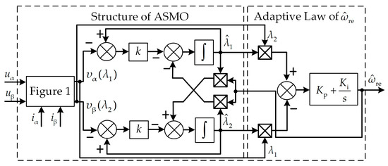
Figure 2.
Block diagram of adaptive sliding mode observer (ASMO) based on EF.
To avoid the error accumulation caused by the integrator, the rotor position is obtained with and directly. That is
2.2. Sensorless-MTPA Control Scheme
The structure block diagram of the MTPA control when the position sensor of the IPMSM is absent is shown in Figure 3a, and the currently common scheme is shown in the left part of Figure 3b, i.e., a model reference adaptive observer (MRAS) is added to observe the d-q axis inductances on the basis of a SMO obtaining the rotor position, and then the sensorless control and MTPA control of the motor are realized respectively. The specific algorithm of the MRAS is shown as follow.
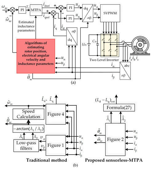
Figure 3.
Control block diagram of maximum torque per ampere (MTPA) control for interior permanent magnet synchronous motor (IPMSM) without position sensor: (a) Overall block diagram; (b) specific algorithms.
Commonly, the motor is chosen as the reference model of MRAS and on the basis, the adjustable model of MRAS is constructed. The adaptive law of MRAS can be obtained with Popov hyperstability theory. According to [7], the d-q axis inductances adaptive law of MRAS can be expressed as
where and are the initial values of the d-q axis inductances, and are the estimated values of the d-q axis inductances, Kp1, Kp2 and Ki1, Ki2 are the coefficients of the adaptive law in MRAS.
The block diagram of inductance parameters identification based on MRAS is shown in Figure 4. And the motor speed information can be obtained from the estimated rotor position information by a moving average or phase-locked loop (PLL) [11].
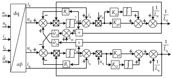
Figure 4.
Block diagram of inductance parameters identification on line based on model reference adaptive observer (MRAS).
It can be seen from the Figure 3 and Figure 4 that the traditional method needs two observers to achieve the MTPA control when the position sensor of the permanent magnet synchronous motor is absent. If the two observers are combined into one, i.e., the inductance information of the motor is observed and the rotor position detection is realized simultaneously, the computation of the control algorithm could be reduced greatly, which is beneficial for facilitating the real-time digital control. The specific principle of the proposed method is explained below.
The MTPA points can be regarded as the solution of the optimal problem for the following formula [14]:
where |is| is the magnitude of the current vector, Te is the electromagnetic torque, np is the number of pole pairs.
With the Lagrange multiplier method adopted to solve the above optimal problem, (25) can be obtained as
where γ is the angle between the stator current vector and the positive direction of the q axis, named current angle and γMTPA is the current angle under the MTPA principle, which can be expressed as
The key of achieving MTPA control for IPMSM is to obtain the accurate current angle [14]. According to (26), γMTPA is a function of the permanent magnet flux linkage and the motor inductance parameters Ld, Lq. When the motor operates in the constant torque region, the demagnetization strength is weak, so is considered as a fixed value [23] whereas Ld and Lq will change due to the variety of id, iq and the operation temperature. To achieve accurate MTPA control, an additional observer is generally necessary to estimate the Ld and Lq in real time. Nevertheless, it can be seen from (26) that the requirements of obtaining the current angle γMTPA are the stator current |is|, the permanent magnet flux linkage , and the difference between d-axis and q-axis inductances (Ld − Lq). It is not necessary to obtain Ld and Lq respectively. Therefore, under the premise of knowing |is| and , the accurate γMTPA can be solved with (26) as long as (Ld − Lq) is obtained, and thereby the MTPA control can be achieved.
It can be seen from (14) and (15) that the magnitudes of and are the product of and , and contains the difference information between d-axis and q-axis inductances. Therefore, and can be used to extract in real time, and thereby, the difference between d-axis and q-axis inductances can be obtained for MTPA control directly, which can be represented as
where (Ld − Lq)est is the observed difference information between the d-axis and q-axis inductances.
With (27) substituted into (26), a relatively accurate current angle γMTPA can be obtained to achieve MTPA control. The structure block diagram of the proposed MTPA control scheme is shown in the right part of Figure 3b.
2.3. The Digital Implementation of the Proposed Method
To facilitate digital implementation of the proposed method, according to (3), the discrete-time SMO is designed as
where Ts is the sampling period of SMO, , and , represent the observed currents at the kth time step and the (k − 1)th time step respectively, and represent the outputs of the SMO at the (k − 1)th step time.
Similarly, according to (15), the discrete-time adaptive mechanism can be designed as
where represents the estimated electrical angular velocity at the (k − 1)th time step, , and , represent the output of the adaptive mechanism at the kth time step and the (k − 1)th time step respectively.
Finally, according to the Figure 3, the sensorless-MTPA control of the permanent magnet synchronous motor can be realized.
It can be known from (27) that (Ld − Lq)est is related to the magnitude of and . To improve the accuracy of MTPA control, the method in [24] is adopted to compensate the observation error caused by dead-time and nonlinear characteristics of the invertor.
3. Experimental Results
To verify the effectiveness of the sensorless-MTPA control scheme proposed in this paper, the performances of the sensorless control and the MTPA control of this scheme are tested. The experimental platform is shown in Figure 5. The tested motor is an IPMSM, and its parameters are listed in Table 1. The load is provided by an induction motor mounted coaxially with the tested motor. The precise rotor position and speed used as the references are obtained from resolver 15VRX-1004-C26 and the resolver decoder chip AD2S1210. The frequency of PWM is 10 kHz. The control law coefficient in SMO is set as l = 163, the proportionality coefficient of the adaptive mechanism in ASMO is set as k = 1000, the coefficients in the speed adaptive law are set as Kp = 3500 and Ki = 4430,000.
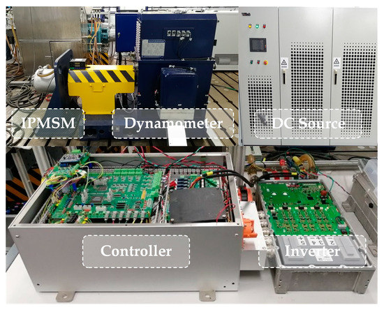
Figure 5.
The experiment platform.

Table 1.
Parameters of the PMSM.
3.1. Sensorless Control Performance
Figure 6 and Figure 7 show the experimental waveforms of increasing/decreasing the load torque. The IPMSM operates at 3000 r/min with the proposed sensorless-MTPA algorithm. The load torque is increased to 60N·m from 0N·m within 1s, and then kept constant for 8s, and finally reduced to 0N·m within 1s. The d-q axis reference currents are provided by the MTPA algorithm proposed in this paper. The experimental waveforms in Figure 6 are the actual d-q axis currents, three-phase currents ia, ib, ic, the input voltages of the ASMO , actual speed n(r/min) and estimated speed (r/min), actual rotor position and estimated rotor position from top to bottom. TL represents the value of the load torque. Figure 7 is the enlarged experimental waveforms in Figure 6. Figure 7a shows the steady state performance when the IPMSM operates at 3000 r/min stably. nerror(r/min) and represent the estimated error of speed and rotor position, respectively. Figure 7b,c shows the dynamic performance of increasing load and decreasing load, respectively.
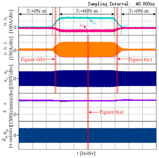
Figure 6.
Experimental waveforms with loads increased and decreased.
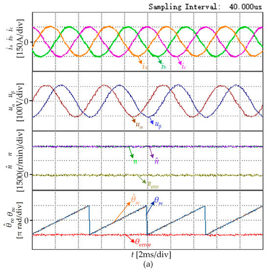
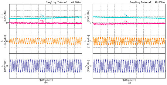
Figure 7.
The enlarged experimental waveforms in Figure 6: (a) Steady state, (b) increase load, (c) decrease load.
It can be seen from Figure 6 and Figure 7 that the actual d-q axis currents can respond quickly with the proposed scheme when the load torque is increased/decreased. Moreover, the three-phase currents of the motor and the input voltages of the ASMO are sinusoidal enough. Simultaneously, there are almost no estimated error in the rotor position and speed, i.e., it is possible to realize the sensorless control with the proposed algorithm when the load torque is increased or decreased.
Figure 8 shows the experimental waveforms of acceleration with the proposed algorithm. Firstly, the motor operates at 1000 r/min stably with the rated load, and then, the speed of the motor is accelerated to 3000 r/min within 1.2 s. The experimental waveforms in Figure 8a are the three-phase currents ia, ib, ic, the input voltages of the ASMO d , actual speed n(r/min) and estimated speed (r/min), actual rotor position and estimated rotor position from top to bottom. Figure 8b is the enlarged waveforms in Figure 8a.
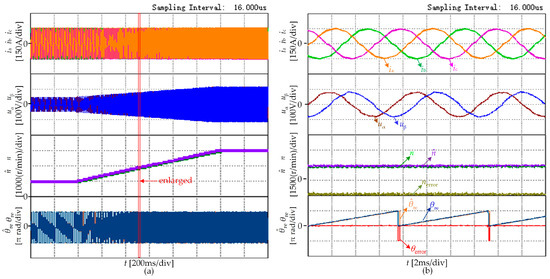
Figure 8.
The experimental waveforms of acceleration: (a) The experimental waveforms of acceleration, (b) the enlarged experimental waveforms in Figure 8a.
It can be seen from Figure 8 that during the acceleration with the rated load, the estimated rotor position and speed can track their actual values fast. Simultaneously, the three-phase currents of the motor and the input voltages of the ASMO are sinusoidal enough, i.e., the acceleration with the rated load can be realized by the proposed scheme.
3.2. Steady State Performance of MTPA Control
To verify the accuracy of the proposed MTPA control algorithm, taking the speed at 1000r/min under sensorless mode as an example, the performance of the MTPA control under different loads is tested, which is shown in Figure 9.
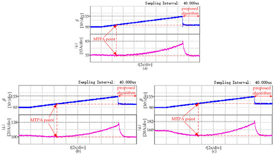
Figure 9.
The experimental waveforms of MTPA control under different loads: (a) load for 20N·m, (b) load for 40N·m, (c) load for 60N·m.
The current vector angle β is defined as the angle between the current vector and the positive direction of d axis in the synchronous coordinate. The relationship between the β and the current angle γ is β = γ + 90°. To find the accurate MTPA point under specific load conditions as a reference, the motor operates in speed control mode. The current vector angle β is increased from 90 degrees to 135 degrees gradually, so the MTPA point is the point with the smallest stator current amplitude in this process. When the current vector angle is increased to 135 degrees, the proposed MTPA control algorithm is enabled. Figure 9 shows the experiment waveforms of the process. The load torques in Figure 9a–c are 20N·m, 40N·m and 60N·m, respectively. Each figure represents the current vector angle β and the stator current amplitude |is| from top to bottom. It can be seen from Figure 9 that under different loads, the stator current amplitude can reach to the minimum value in a short time with the proposed MTPA control algorithm, i.e., the motor tracks the MTPA point in a short time. This experiment verifies the accuracy of the proposed MTPA control algorithm.
3.3. Dynamic Performance of MTPA Control
To verify the dynamic performance of the proposed MTPA control algorithm, it is necessary to obtain the current vector angle curve βMTPA_am in advance as a reference, which is the current vector angle corresponding to the different stator current amplitude under the MTPA principle. Taking the speed at 2000 r/min as an example, the motor operates in torque control mode, and the stator current amplitude of the motor is given to be a constant whereas the current vector angle is gradually increased from 90 degrees to 135 degrees, so the current vector angle that maximizes the electromagnetic torque during this process is the MTPA point corresponding to the specific stator current amplitude. By changing the magnitude of the given stator current amplitude, the above process can be repeated to obtain the current vector angle corresponding to the different stator current amplitudes under the MTPA principle. The obtained experimental results are listed in Table 2. According to the Table 2, the βMTPA_am can be obtained with the curve fitting method.
Table 2.
The current vector angle under MTPA principle.
Figure 10 shows the experimental waveforms of the proposed MTPA control scheme when the load is increased. Firstly, the motor is stably operated at 2000 r/min with the load of 20 N·m, and then the load is increased to 40 N·m within 1 s. After stable operation for 9 s, the load torque is increased to the 60 N·m within 1 s. The experimental waveforms are the actual d-q axis currents id, iq and their reference values idref, iqref, the actual current vector angle of the motor βreal and the reference value βMTPA_am from top to bottom. βreal is the actual current vector angle waveform with the proposed sensorless-MTPA control scheme.
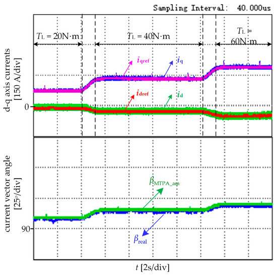
Figure 10.
The dynamic experimental waveforms of MTPA control.
It can be seen from Figure 10 that βreal can track βMTPA_am well and the id, iq can also follow the idref, iqref well when the load torque is changed. This experiment verifies the accuracy of the MTPA control algorithm when the load is changed, i.e., the MTPA control of the proposed scheme has a good dynamic performance.
4. Conclusions
To achieve the MTPA control when the position sensor of the IPMSM is absent, the traditional method needs to add an observer to identify the d-q axis inductances on the basis of the sensorless algorithm, which increases the complexity of the control algorithm. Aiming at the phenomenon, a sensorless-MTPA control scheme of the IPMSM is proposed in this paper. The main contribution of the paper is shown as follows.
- (1)
- By analyzing the mathematical model when the IPMSM operates in the steady state, an adaptive mechanism is adopted to construct an ASMO. The stability of the SMO and the adaptive mechanism are ensured with the Lyapunov criterion. Different from the traditional SMO, the ASMO can observe the rotor position and speed information without low-pass filters so that the problems of the dc drift and phase delay can be suppressed to some extent.
- (2)
- Different from the traditional method to achieve the MTPA control when the position sensor of the IPMSM is absent, a sensorless-MTPA control scheme is proposed by analyzing the principle of the MTPA control. In the proposed method, the designed ASMO not only observes the rotor position and speed but also relies on the difference between d-axis and q-axis inductances to obtain the MTPA points directly so that the MTPA control can be achieved simultaneously without adding an observer.
- (3)
- The proposed sensorless-MTPA control scheme is realized on a 20 kW IPMSM where the sensorless control performance and the MTPA control performance are tested. The feasibility and effectiveness of the proposed method are verified by the experiment’s results.
Author Contributions
Conceptualization, M.Y., T.S. and H.W.; methodology, C.X. and H.W.; validation, X.L., M.Y. and T.S.; formal analysis, M.Y. and H.W.; writing—original draft preparation, M.Y. and X.L.; writing—review and editing, M.Y., T.S. and C.X.; funding acquisition, T.S. and C.X.
Funding
This research received no external funding.
Acknowledgments
The authors are grateful to the financial support from Major Program of the National Natural Science Foundation of China under grant 51690183 and in part by the National Natural Science Foundation of China under grant 51777135.
Conflicts of Interest
The authors declare no conflict of interest.
References
- Sul, S.; Kwon, Y.; Lee, Y. Sensorless control of IPMSM for last 10 years and next 5 years. CES Trans. Electr. Mach. Syst. 2017, 1, 91–99. [Google Scholar]
- Karady, G.; Holbert, K. Introduction to Power Electronics and Motor Control. In Electrical Energy Convers and Transport: An Interactive Computer-Based Approach, 2nd ed.; Wiley-IEEE Press: New York, NY, USA, 28 May 2013; pp. 854–884. [Google Scholar]
- David, G.; Meki, A.; Bown, N.; Gerada, C. High-Speed Electrical Machines: Technologies, Trends, And Developments. IEEE Trans. Electron. 2014, 61, 2946–2959. [Google Scholar]
- Minh, X.; Guan, D.; Xiao, D.; Rahman, M. A Modified Sensorless Control Scheme for Interior Permanent Magnet Synchronous Motor over Zero to Rated Speed Range Using Current Derivative Measurements. IEEE Trans. Electron. 2019, 66, 102–113. [Google Scholar]
- Wang, G.; Xiao, D.; Zhao, N.; Zhang, X.; Wang, W.; Xu, D. Low-Frequency Pulse Voltage Injection Scheme-Based Sensorless Control of IPMSM Drives for Audible Noise Reduction. IEEE Trans. Ind. Electron. 2017, 64, 8415–8426. [Google Scholar] [CrossRef]
- Wang, G.; Yang, L.; Zhang, G.; Zhang, X.; Xu, D. Comparative Investigation of Pseudo random High-Frequency Signal Injection Schemes for Sensorless IPMSM Drives. IEEE Trans. Power Electron. 2017, 32, 2123–2132. [Google Scholar] [CrossRef]
- Wu, J.; Wei, H.; Zhang, Y. Sensorless vector control of permanent magnet synchronous motor based on model reference adaptive system. In Proceedings of the Third IEEE International Conference on Computer and Communications (ICCC), Chengdu, China, 13–16 December 2017; pp. 2879–2883. [Google Scholar] [CrossRef]
- Zhu, G.; Wang, G.; Ni, R.; Xu, D. Active flux based full-order discrete-time sliding mode observer for position sensorless IPMSM drives. In Proceedings of the Seventeenth International Conference on Electrical Machines and Systems (ICEMS), Hangzhou, China, 22–25 October 2014; pp. 3569–3572. [Google Scholar]
- Tang, H.; Li, H.; Lin, J. Research on Sensorless Control Method of PMSM Based on a Kalman Filter Sliding Mode Observer. In Proceedings of the 10th International Conference on Measuring Technology and Mechatronics Automation (ICMTMA), Changsha, China, 10–11 February 2018; pp. 290–293. [Google Scholar]
- Chen, Z.; Tomita, M.; Doki, S. An extended electromotive force model for sensorless control of interior permanent magnet synchronous motors. IEEE Trans. Ind. Electron. 2003, 50, 288–295. [Google Scholar] [CrossRef]
- Zhao, Y.; Zhang, Z.; Qiao, W.; Long, W. An Extended Flux Model-Based Rotor Position Estimator for Sensorless Control of Salient-Pole Permanent-Magnet Synchronous Machines. IEEE Trans. Power Electron. 2015, 30, 4412–4422. [Google Scholar] [CrossRef]
- Jiang, Y.; Xu, W.; Mu, C.; Zhu, J. An Improved Third-Order Generalized Integral Flux Observer for Sensorless Drive of PMSMs. IEEE Trans. Ind. Electron. 2018, 6, 278–289. [Google Scholar] [CrossRef]
- Li, K.; Wang, Y. Maximum Torque Per Ampere (MTPA) Control for IPMSM Drives Based on a Variable-Equivalent-Parameter MTPA Control Law. IEEE Trans. Power Electron. 2019, 34, 7092–7102. [Google Scholar] [CrossRef]
- Tang, Z.; Li, X.; Dusmez, S. A New V/f-Based Sensorless MTPA Control for IPMSM Drives. IEEE Trans. Power Electron. 2016, 31, 4400–4415. [Google Scholar] [CrossRef]
- Cao, M.; Egashira, J.; Kaneko, K. High efficiency control of IPMSM for electric motorcycles. In Proceedings of the IEEE 6th International Power Electronical Motion Control Conference, Wuhan, China, 17–20 May 2009; pp. 1893–1897. [Google Scholar]
- Shi, C.; Luo, J.; Huang, J.; Yu, Z.; Wen, C. New Sensorless Control for Interior Permanent Magnet Synchronous Motors of Electric Vehicle. In Proceedings of the 2nd IEEE Conference on Energy Internet and Energy System Integration (EI2), Beijing, China, 20–22 October 2018; pp. 1–5. [Google Scholar]
- Wang, G.; Li, Z.; Zhang, G.; Yu, Y.; Xu, D. Quadrature PLL-based high-order sliding-mode observer for IPMSM sensorless control with online MTPA control strategy. IEEE Trans. Energy Conversat. 2013, 28, 214–224. [Google Scholar] [CrossRef]
- Sun, T.; Wang, J.; Chen, X. Maximum torque per ampere (MTPA) control for interior permanent magnet synchronous machine drives based on virtual signal injection. IEEE Trans. Power Electron. 2015, 30, 5036–5045. [Google Scholar] [CrossRef]
- Tomastu, S.; Kondo, S.; Tomita, M.; Mattsumoto, A. A design method of full-order flux observer for realization of both MTPA control and position sensorless control of IPMSM. In Proceedings of the IEEE 2nd International Future Energy Electronics Conference (IFEEC), Taipei, Taiwan, 1–4 November 2015; pp. 1–5. [Google Scholar]
- Qiao, Z.; Shi, T.; Wang, Y.; Yan, Y.; Xia, C.; He, X. New Sliding-Mode Observer for Position Sensorless Control of Permanent-Magnet Synchronous Moto. IEEE Trans. Ind. Electron. 2013, 60, 710–719. [Google Scholar] [CrossRef]
- Liu, J.; Nondahl, T.; Schmidt, P.; Royak, S.; Harbaugh, M. Rotor position estimation for synchronous machines based on equivalent EMF. IEEE Trans. Ind. Appl. 2011, 47, 1310–1318. [Google Scholar]
- Rafaq, M.; Mwasilu, F.; Kim, J. Online Parameter Identification for Model-Based Sensorless Control of Interior Permanent Magnet Synchronous Machine. IEEE Trans. Power Electron. 2017, 32, 4631–4643. [Google Scholar] [CrossRef]
- Jung, H.; Park, G.; Kim, D.; Jung, S. Optimal Design and Validation of IPMSM for Maximum Efficiency Distribution Compatible to Energy Consumption Areas of HD-EV. IEEE Trans. Magn. 2017, 53, 1–4. [Google Scholar] [CrossRef]
- Ryu, H.; Lim, L.; Lee, J.; Hwang, S.; Kim, J. A Dead Time Compensation Method in Voltage-Fed PWM Inverter. IEEE Trans. Energy Convers. 2012, 25, 1–10. [Google Scholar]
© 2019 by the authors. Licensee MDPI, Basel, Switzerland. This article is an open access article distributed under the terms and conditions of the Creative Commons Attribution (CC BY) license (http://creativecommons.org/licenses/by/4.0/).