Abstract
This paper presents the results of laboratory tensile testing of segmentally-installed glue-in roof bolting. We studied roof bolting of the type Olkusz-16A (Boltech Sp. z o.o., ZGH Bolesław S.A., Bukowno, Poland), additionally equipped with a steel rod coil, which was mounted in steel cylinders filled with a concrete mixture using multi-part resin cartridges with a diameter of 0.024 m and length of 0.045 m. The mounting depths were 0.1 m and 0.2 m, respectively. Our main purpose was to determine the effect of the bolt hole diameter, which assumed the values 0.028 m, 0.032 m, 0.035 m, and 0.037 m, respectively, on the load-bearing capacity of the roof bolting in relation to the mounting depth. We found that the mounting depth of 0.2 m was sufficient for the roof bolting to exhibit its full load and displacement properties for all four diameters of the bolt hole. To determine whether the roof bolting was capable of transferring the load in situ, we presented the results of the predicted load on the roof bolting applied in a room and pillar mining method in an underground mine of zinc and lead ore deposits. Our objective was to determine the influence of the room and pillar mining method geometry on the range of the fault zone of rocks around pits. We designed the deposit excavation model using the Examine3D numerical modeling software, which is based on the boundary element method. We created three-dimensional models for three variants of working space opening widths: featuring two, three, and four rows of rooms. The geometry of rooms and pillars corresponded to the mine conditions; the width, height, and length parameters were all 5 m. We determined the strength, strain, and structural parameters of the rock mass on the basis of laboratory studies of the drill core and rock forms collected from the room longwall. We used the strength factor to specify the maximum range of the fault zone of rocks around pits. In the last stage of research, we compared the load value obtained based on numerical testing with the maximum load obtained in the tensile strength tests of the roof bolting and determined the safety factor of the segmentally-installed roof bolting.
1. Introduction
Roof bolting, both adhesive and sleeve-anchor installed, is very common in room and pillar mining methods for protecting pits against roof rock cave-ins. Roof bolting is used in both ore and coal mining, installed segmentally or over the whole length using quick-setting and slow-setting resin cartridges. Glue-in roof bolting is installed in long-term preparatory excavations, short-term mining excavations, and in the fractured rock mass, where the expansive head cannot expand against the walls of the bolt hole [1]. In underground mines it often happens that locally, along the boreholes drilled for the bolt, fractured zones (or even bigger gaps) are met, so the diameter is oversized, the contact may be insufficient, and finally, the expansion head will not be effective. The advantage of segmentally installed glue-in roof bolting (Figure 1a) is that it is possible to increase its load-bearing capacity by using a longer installing segment. The diameter and length of the cartridge should be selected in such a way as to reach the full load and displacement properties of the roof bolting. This type of optimization is a significant factor in reducing production costs. Moreover, under shifting geological conditions, a change in the bolting technology is not problematic for roof bolter operators with experience in handling adhesive cartridges. At same locations, the same kinds of rocks may be softer or harder, more or less fractured, fractures may be filled with stronger or weaker material, separated or compacted, wet or dry. All these features may affect the final quality of the roof bolting. The change only involves the addition of several additional cartridges. Some doubts arise from the fact that in a fractured rock mass, the resin cartridge may not be correctly mixed, as the resin will have a tendency to move towards the cracks. Campbell et al. [2] found that an important issue to be considered is the packaging of the resin cartridge, which might serve as a plug that prevents the full utilization of the cartridge mass. Glue-in roof bolting installed along its whole length (Figure 1b) is usually used in a layered rock mass, where the joint activity of the bolting and the rock mass is based on layer fastening [3]. It should be noted that installation along the whole length of the roof bolting using resin cartridges can cause the bolting to become very stiff. Roof bolting stiffness is determined by the load transfer mechanism at the contact point between the rock mass, resin, and the bolting [4]. Due to very slight deformations, this type of bolting is not recommended for the roof layers of the rock mass which are inclined to bending. Rock bolts may be installed in the hole using quick-setting and slow-setting cartridges (Figure 1c). For example, in Polish underground copper mines, quick-setting resin cartridge and three or four slow-setting cartridges with a diameter of 0.024 m and length 0.45 m are used [5]. This makes it possible to preload. Due to different gelation times, roof bolting should be installed by experienced operators to prevent the premature shearing of the resin at the point of contact between the rock mass and resin or resin-rod during the rotational movement of the rock bolt [6]. Selecting the technology for installing roof bolting on quick-setting or slow-setting cartridges should be based on striking a balance between the install of potential excavations designated for bolting and the time needed to secure them.

Figure 1.
Schemes for fixing bolts into holes using resin cartridges; (a) segmentally, (b) along the whole length with the same binding agent; (c) along the whole length, using two agents, quick-setting and slow-setting; 1, 6—binding agent; 2—rock bolt; 3—empty space; 4—washer; 5—nut; 7—quick-setting agent; 8—slow-setting agent.
The diversity of conditions under which roof bolting is used requires achieving a joint effect at the roof bolt-resin cartridge (binding agent)–rock mass contact point. Under laboratory conditions, the roof bolting is installed to the drill core [7,8], or the rock mass is simulated using a concrete mix glued to the steel cylinders [9,10]. Marcon et al. [11] divided the failure mechanisms of the glue-in roof bolting under tensile loading into four mechanisms: concrete cone failure, combined failure, splitting failure; and steel failure. Kilic et al. [12] examined the influence of the binding agent on the load-bearing capacity of glue-in ribbed bolts along the whole length in a basalt block. Kilic et al. [13] presented the influence of rock bolt geometry on transferring the load for adhesive installing along the whole length. Li et al. [14] defined the influence of the critical installation depth of the rock bolt with a diameter of 0.020 m on the load-bearing capacity, depending on the binding agent’s uniaxial compressive strength. Martin et al. [15] found that the phenomenon occurring at the bolt-binding agent contact point can be described using four parameters: shear stress, shear-and-slide, radial pressure, and radial displacement. Ma et al. [16] developed an analytical model of roof bolting behavior along the whole length under tensile stress, based on the assumption of a correlation between the properties of the binding agent and sliding. Hagan [17] found that for a bolt with a diameter of 0.025 m, the maximum bolt hole diameter should not exceed 0.035 m.
2. Room and Pillar Methods in Hard Rock Mining
Room and pillar mining methods are used in ore mines and also in coal and chemical resources mines [18,19]. Pillars of various shapes and cross-sections (continuous, square, round, rectangular) are placed between rooms. They are meant to ensure the stability of the post-excavation area (the field or its part). For new fields of exploitations, in which the room and pillar method will be used, monitoring systems of the rock bolt support are designed to optimize the bolting technological parameters [20]. Room and pillar mining methods are dedicated to horizontally or slightly inclined orebodies. For example, in some underground copper mines, at the first stage of this technology, several usually parallel rooms are driven to extract the minerals with drilling and blasting method using explosives. In the same way, as the second phase of the technology, similar perpendicular excavations are constructed. Finally, between the intersecting excavations, some parts of the orebodies are left in their original location, forming pillars [21]. Their role is to support overlying rocks and secure their stability and work safety for miners. Usually, the pillars are insufficient from a stability point of view, and therefore, additional reinforcement is applied using rock bolting as the most effective way. The room and pillar mining method is a very effective and one that enables a high level of mechanization of the technology. The uncovered roof area increases with the progress of orebody excavation, and the pillars sustain an increasing value of loads from the rock mass. For the adopted system geometry, the opening width of the working area and the correct selection of pillar and room dimensions are vital to ensure safe operating conditions with minimum losses of the mineral being mined [22]. Under complex geological and mining conditions, the distribution of stresses in individual pillars, as well as in the mining field, is difficult to accurately predict. This makes it necessary to adopt certain simplifying assumptions. Methods in which pillars between rooms work with the rock mass as the main independent construction elements to bear the loads from their designated rock columns are common in engineering calculations [23]. There are also methods in which the load-bearing structure comprises pillars between rooms and a compact layer of roof rocks, which absorb the load from the remaining layer of the overlying rocks. In addition to this, the pillars between rooms can absorb the load of the unloaded part of the roof, while cooperating with the overlying layer of compact rock (main roof) in transferring the loads of the overlying overburden layers [24].
2.1. Geological Conditions of the Modelled Ore Mine
Zinc and lead ore deposits are classified as Mississippi Valley sedimentary deposits. These are stratoid and lentiform-nestlike deposits. Mineralization is present in a given lithostratigraphic horizon and is connected with a specific lithology, the so-called metalliferous dolomites from the Middle Triassic (middle and lower Muschelkalk), rarely Lower Triassic (Röt). The pits are excavated in layers I, III, III in metalliferous dolomites (Figure 2). Metalliferous dolomites are developed as grey dolomites, finely crystalline, cracked and cavernous in parts, mostly highly compact. In oxidized areas, dolomites can be highly weathered, with a brown and rusty color. The deposits are irregular, brecciated, and feature variable quality parameters. There are minor metasomatic deposits in the form of pseudo-beds. The most common minerals in the primary deposit include sphalerite, wurtzite, colomorphous zinc blende, galena, marcasite, and pyrite. Calcite, aragonite, baryte, and monheimite are found along with sulfides in the peripheral zones of ore bodies. In the weathering zone, sulfide ores are replaced by calamines (smithsonite, goethite, cerusite, hemimorphite, anglesite, and hydrozincite).
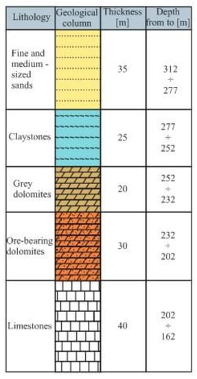
Figure 2.
Lithological profile.
Monkey drifts are located in a 100 m × 100 m arrangement, which involves isolating mining fields with an area of 1 ha. The field is divided by drifts (known as extraction drifts) into mining pillars with widths up to 25 m. The isolated pillars are excavated in 5 m-wide rooms tunnels in parallel to the mining face line. The maximum opening of the mining face ceiling depends on the strength of rocks and usually covers two rows of rooms and two lines of pillars. If no strong layers are present in the overburden and with a sufficiently large span of the mining field, the pillars are loaded with the whole column of overlying rocks. This assumption is used in mines if there is a strong load-bearing layer (core roof) and if the ratio of mining field width to the excavation depth is larger than 1. For a small span of the mining field, when the ratio of field width to excavation depth is lower than 1 and the pillars between rooms are highly flexible, it is assumed that a relieved zone (elliptical) is formed over the mining field and the pillars between rooms are loaded only with a column of rocks contained in the relieved zone. This assumption is correct when the immediate roof is located over the pillars. The loads from the remaining column of rocks are transferred individually by the wide field pillars or by the undisturbed face. If we assume the elliptical shape of the relieved zone (Figure 3), the permissible uncovering of the main roof can be calculated according to formula [25]:
where:

Figure 3.
Pillar loading diagram; L—permissible main roof uncovering, I—distance between pillar axes, f—height of vault (relaxed zone) in the roof, b—thickness of the immediate roof, h—thickness of the main roof, H—excavation depth.
- Ts—tensile strength of the main roof rocks, /MPa,
- h—thickness of the main roof (load-bearing layer), /m,
- q—unit pressure of the main roof, /MPa,
- b—thickness of the immediate roof, /ᵒ,
- —deflection angle of the immediate roof layers, /ᵒ.
Boulders of grey metalliferous dolomites with a compact, random structure, were collected from the face of room No. 3 (Figure 4a), the unloading grate (Figure 4b), and in the form of a drill core with a diameter of 0.102 m from the roof of the excavation section at a depth of 110 m below ground. The width, length, and height of the rooms and pillars in the excavation section are 5 m. We extracted regular cylindrical samples with a diameter of 50 mm and a height of 100 mm from the boulders (Figure 5a) and the drill core (Figure 5b). Then we tested the rock samples using a universal testing machine to determine the uniaxial compressive strength and Young’s modulus or Poisson number (Figure 5c). The test results demonstrated a compressive strength of 31 MPa, Young’s modulus of 14.700 MPa, and Poisson number of 0.22, while bulk density was equal to 27 kN/m3.
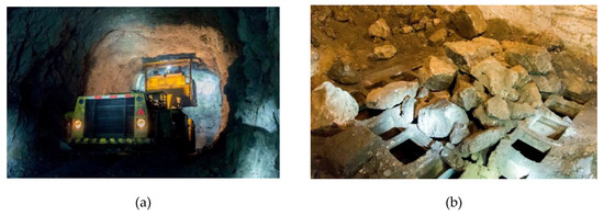
Figure 4.
Sampling location; (a) forehead of room No. 3, (b) section grate.

Figure 5.
Samples prepared for research; (a) dolomite boulders with holes where samples have been cut; (b) drill cores collected from the roof of the excavation room; (c) an example sample after compressive strength testing.
2.2. Numerical Modeling of Fault Zones around Pits
We prepared a model deposit excavation using a room and pillar mining method in three variants: with two, three, and four rows of pillars (Figure 6a–c) and rooms using the Examine3D software based on the boundary element method. Boundary value problems involve seeking solutions to partial or ordinary differential equations describing a phenomenon occurring in a continuous medium. Functions fulfilling the equations assuming the imposed boundary conditions constitute their solutions. The boundary element method involves the use of a fundamental solution to a given differential equation and requires the approximation of the function constituting the solution only at the boundary of the area, using the so-called boundary elements. These elements are lines in two-dimensional problems and polygons in three-dimensional problems. Selecting this method resulted from the possibility of simplifying mathematical operations, particularly in three-dimensional tasks, which was connected to the discretization of not the whole area, but only its limits. We also took into account the possibility to calculate, in linear tasks, the values being investigated not only at nodes but also at any point of the area, without the need to approximate, which was particularly important for zones with considerable function gradients.
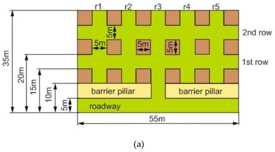

Figure 6.
An example diagram of a room and pillar mining method; (a) two-row; (b) three-row; (c) four-row; ri—room number.
We adopted the Hoek–Brown failure criterion [26], taking into account uniaxial compressive strength and empirical material constants m and s selected using RocLab software [26]. The strength, strain, and structural parameters were selected according to the laboratory tests of boulders. Analysis and determination of fault zones in the rock mass around pits in the numerical model used the strength factor (SF) expressing the relationship between rock strength and the equivalent stress at a given point. If the SF value is lower than 1, the equivalent stress exceeds the strength of the rock mass at the point, and material failure may occur (plastic analysis). Assuming that the system is elastic, no material failure occurs. The results for the fault zone range of rocks around room pits are presented in Figure 7a–c. In each of the figures, we created an isosurface with a value of 1 and two cross-sections (A-A and B-B), perpendicular to each other, with the maximum range of the fault zone marked on them.
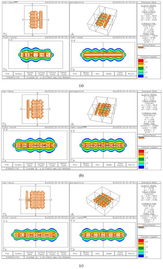
Figure 7.
The ranges of the strength factor zone of the rocks around room pits. (a) Two rows of rooms; (b) three rows of rooms; (c) four rows of rooms.
The maximum ranges of the stress zone of the rocks in the roof of room pits for two, three, and four rows were 0.91 m, 0.93 m, and 0.95 m, respectively. Assuming the roof bolting–rock mass cooperation model, according to the theory of suspension of weak layers to overlying stronger layers (Figure 8) and taking into account the bolt span in the mine (1 m × 1 m), the load on the roof bolting can be calculated using the following formula:
where:
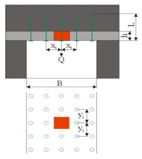
Figure 8.
Suspended layer model.
- Cb—load-bearing capacity of the roof bolting, /kN,
- Q—weight of the weak layer supported by one bolt, /kN,
- n—safety factor (1.5 < n < 3),
- γ—unit weight of the weak layer, /kN/m3, (27 kN/m3),
- B—room width, /m, (5 m),
- h—range of the weak layer (fault zone), /m,
- x1, y1—bolt span, /m, (1 m).
Using formula 1 and taking into account the safety factor of 3, we calculated the load per bolt, which for two, three, and four rows was 73.71 kN, 75.33 kN, and 76.95 kN, respectively. Knowing the range of the fault zone of roof rocks and based on mining experience, the length of the roof bolting (L) can be obtained from the formula:
The roof bolting length was determined as 1.6 using formula 2, We adopted this length for further laboratory research, in which we determined the influence of the installation depth and bolt diameter on load-bearing capacity.
3. Assessing the Influence of Adhesion Length on the Load-Bearing Capacity of Roof Bolting
The laboratory tests of the glue-in roof bolting were conducted at the Department of Underground Mining of the Faculty of Mining and Geoengineering, AGH in Kraków. The tested roof bolting was Olkusz-16A [5]. The roof bolting was composed of a 1.6 m-long ribbed pole made of EPSTAL steel (grade B500SP). This steel provides enhanced ductility. Steel is characterized by yield strength R from 500 MPa to 625 MPa, and the minimum percentage of elongation A5 is equal to 16% [27]. In addition, the bolt was equipped with a steel rod with a diameter of 0.006 m (St0 steel grade) coiled along a 0.6 m section, the purpose of which was to mix the resin cartridge (Figure 9a,b). Bolt diameter with a rod coil was 0.024 m. The height of the bolt rib was 0.0013 m, the width was 0.0033 m, and the span was 0.005 m, 0.01 m, and 0.015 m. The bolt cooperated with the triangular flat steel bearing plate, sheet width 0.006 m and side length 0.205 m. The base was made of St3SAL grade steel. An M16 nut with a height of 0.01875 m made of St5 steel was placed on the threaded section of the bolt (Figure 9a).
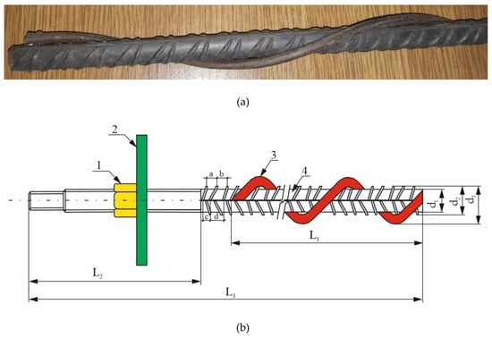
Figure 9.
Olkusz-16A glue-in bolt. (a) General view; (b) bolt with elements, 1—M16 nut, 2—bearing plate, 3—steel rod spiral, 4—ribbed rod, a, b, c, d—spans between ribs: 0.01 m, 0.01 m, 0.05 m, 0.015 m, L1—length of rod coil (0.6 m), L2—length of M16 rod thread (0.096 m), L3—rod length (1.6 m), d1—diameter of rod core (0.0154 m), d2—diameter of rod with ribs (0.018 m), d3—diameter of rod with coil (0.024 m).
At the laboratory test stand, we simulated the rock mass using a concrete block made of a mixture of sand with a particle size of 0.002 m, 42.5R-class Portland cement, diabase aggregate with a particle size from 0.002 m to 0.005 m. The water-to-cement ratio was 0.45. The concrete mixture was also enriched with the Sika ViscoCrete-20HE superplasticizer and the SikaFume-HR/-TU silica fume. Uniaxial compressive strength tests and tensile strength tests (Brasilian test) of cubic concrete samples with 0.15 m-long sides (Figure 10a) were performed using a Controls Automax5 universal testing machine (Figure 10a,b) equipped with Microdata Autodriver software (ver. 1, Controls S.p.A., Milan, Italy). The load speed was 0.6 MPa/s for compressive force and 0.1 MPa/s for tensile force.

Figure 10.
Cubic concrete blocks with 0.15 m-long sides; (a) general view; (b) uniaxial compressive strength test; (c) tensile strength test (Brazilian test).
After determining a satisfactory compressive strength within the range from 45 MPa to 50 MPa and tensile strength between 4.1 MPa and 4.7 MPa, we started to fill the steel cylinders (0.1 m diameter, 0.1 m length, and 0.005 m sheet thickness) with concrete mixture. Twenty-eight days after filling the steel cylinders, we drilled holes with diameters 0.028 m, 0.032 m, 0.035 m, and 0.037 m in them. We used SDS Max hammer drills for drilling in concrete with cemented carbide heads and a core drill (Figure 11).
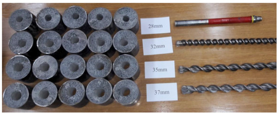
Figure 11.
Steel cylinders filled with a concrete mix.
The rock bolt was installed in holes using resin cartridges produced by PRIG [28]. A 0.45 m-long resin cartridge with a diameter of 0.024 m and the setting time of 10 minutes (Figure 12a) is composed of a polyamide casing filled with a resin compound, which includes limestone filler (chalk), polyester resin, and amine-type curing accelerator (N,N-Dimethyl-p-toluidine), inside which there is a glass capsule filled with a polymerization initiator in the form of dibenzoyl peroxide The installing depth was 0.1 m and 0.2 m (Figure 12b,c). Figure 12b shows several types of rods, of which the second from the left are Olkusz-16A bolts.
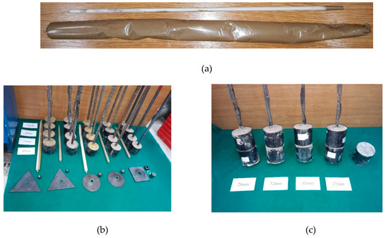
Figure 12.
Segmentally installed bolts in concrete model holes using resin cartridges with installing depths. (a) General view of resin cartridge; (b) 0.1 m, (c) 0.2 m.
The Load and Displacement Properties of Segmentally Installed Glue-in Roof Bolting
Segmentally installed glue-in roof bolting was subjected to tensile tests using a universal testing machine in the bolt laboratory of the Department of Underground Mining. Five bolts were tested for each hole diameter. The laboratory test stand (Figure 13a,b) is equipped with a QUANTUM MX840A measurement amplifier (HBM, Spectris plc, Darmstadt, Germany), to which force and displacement sensors are connected [29]. The load increment speed was 0.5 kN/s. The amplifier is connected to a computer with Catman–Easy software installed, which allows live tracking of the load and displacement properties. Tensile strength test results for glue-in Olkusz-16A roof bolting installed along 0.1 m and 0.2 m sections for hole diameters 0.028 m, 0.032 m, 0.035 m, and 0.037 m are presented in Figure 14a–h, Figure 15a–h and Table 1.
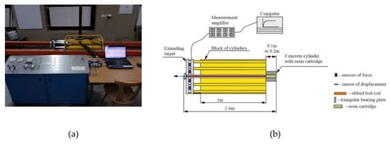
Figure 13.
Method of applying bolt loads at the laboratory stand. (a) Test station; (b) bolt loading scheme.
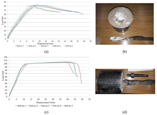

Figure 14.
The load and displacement properties of the glue-in Olkusz-16A roof bolting segmentally installed along 0.1 m for diameter (a) 0.028 m; (b) extension from the hole with a diameter of 0.028 m; (c) 0.032 m; (d) thread stripping in the hole with a diameter of 0.032 m; (e) 0.035 m; (f) extension from the hole with a diameter of 0.035 m; (g) 0.037 m; (h) extension from the hole with a diameter of 0.037 m.
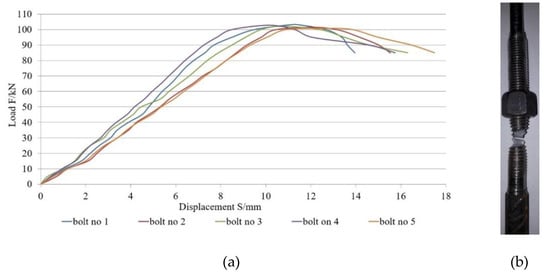

Figure 15.
The load and displacement properties of the glue-in Olkusz-16A roof bolting segmentally installed along 0.2 m for diameter (a) 0.028 m; (b) thread stripping in the hole with a diameter of 0.028 m; (c) 0.032 m; (d) thread stripping in the hole with a diameter of 0.032 m; (e) 0.035 m; (f) thread stripping in the hole with a diameter of 0.035 m; (g) 0.037 m; (h) thread stripping in the hole with a diameter of 0.037 m.

Table 1.
Comparison of the results for the influence of installing depth on the load-bearing capacity of the Olkusz-16A roof bolting.
4. Discussion
We used numerical modeling to find the maximum range of the fault zone of the rocks around the pits in a room and pillar mining method. For the first model of deposit shearing covering two rows of pillars and rooms, both for the A-A and the B-B cross-sections, the range of the fault zone in roof rocks was 0.91 m. For the second model, involving three rows of pillars and rooms, the range increased by 0.02 m. For the third model, which involved four rows of pillars and rooms, the range of the fault zone calculated using the strength factor was the largest, ainstalling to 0.95 m. Assuming that the load per bolt corresponds to a cuboid with its base being a 1 m × 1m span of bolts and height corresponding to the range of the fault zone of rocks, taking into account the unit weight of rocks contained within the delimited solid body, it can be stated that the difference in maximum load for all three models does not exceed 4 kN. On the basis of laboratory tensile testing of glue-in roof bolting segmentally installed using resin cartridges, it can be concluded that for the installing depth of 0.1 m, the full load and displacement properties were reached only for the hole diameter of 0.032 m, as in this case, the material discontinuity occurred over the lowest diameter of bolt core. For the remaining diameters, i.e., 0.028 m, 0.035 m, and 0.037 m, the extension of the rod from the hole was observed. The difference in load-bearing capacity between diameters 0.028 m and 0.035 m was only 1.05 kN. Much bigger differences were observed between diameters 0.028 m and 0.035 m and the highest diameter being 0.037 m, which were 9.51 kN and 10.56 kN, respectively. For the installing depth of 0.2 m, all four bolt hole diameters reached full load and displacement properties. The highest load-bearing capacity was recorded for the diameter of 0.032 m, which was higher than for 0.028 m, 0.035 m, and 0.037 m, by 8.23 kN, 11.85 kN, and 9.69 kN, respectively. Assuming that the roof bolting installed along a 0.2 m section will have a safety factor of 3 and taking into account the maximum load-bearing capacities of the roof bolting obtained in laboratory tests, it can be concluded that for the first model of deposit excavation, the reserves of load-bearing capacity for diameters 0.028 m, 0.032 m, 0.035 m, and 0.037 m are 29.46 kN, 37.69 kN, 25.84 kN and 28 kN, respectively. For the second model, the load-bearing capacity reserves for the same diameters in comparison with the first model are 1.62 kN smaller. The smallest load-bearing capacity reserves are found for the largest deposit excavation, where the differences between the actual load and the maximum load-bearing capacity of bolts for the bolt hole diameters of 0.028 m, 0.032 m, and 0.037 m are 23.22 kN, 31.45 kN, 19.6 kN, and 21.76 kN. For the installing depth of 0.1 m, only for the diameter of 0.032 m, the load-bearing capacity reserves for the first, second and third models are 33.16 kN, 31.54 kN, and 26.92 kN, respectively. When we compared the values of load-bearing capacity for installing lengths 0.1 m and 0.2 m for the bolt hole diameter of 0.032 m, it can be stated that the installing length 0.2 m has a 0.453 kN higher load-bearing capacity reserve for the first, second, and third deposit excavation model. According to Polish regulations [30], the minimum load-bearing capacity of glue-in roof bolting in zinc and lead ore mining should be at least 90 kN. The obtained laboratory test results indicated that the safety factor for the roof bolting installed along a section of 0.1 m with a diameter of 0.032 m was 1.18 for the installing depth of 0.2 m and for diameters 0.028 m, 0.032 m, 0.035 m, and 0.037 m—1.14; 1.23; 1.10; 1.13. The load and displacement properties were investigated in the loading tests of bolts for two installing depths in the hole z, i.e., for z = 0.1 m and z = 0.2 m, and for the following four diameters of bolt holes: d = 0.028 m; 0.032 m; 0.035 m, and 0.038 m. The full specifications presented in Figure 14a,c,e,g and Figure 15a,c,e,g show the changes in the values of loads as functions of displacements S measured at the test station. These values resulted from the elongation of the bolt ΔL depending on the value of the active force (stress) and strain characteristics of the material of which it was made (in the analyzed case the properties of steel) and were also affected by the extension of the bolt from the hole ΔW. The figures presented above show two phases of function behavior: A and B. Phase A was characterized by increases in load accompanying increases in displacements until the maximum value of the force equal to the bolt’s maximum load-bearing capacity was achieved, while phase B involved a much faster increase in displacements S with relatively low changes in the value of the tensile force recorded. Figure 16a–d and Figure 17a–d present the results of an analysis of phase A, corresponding to the range of the required load-bearing capacity of a bolt in an ore mine, with the following assumptions:
S = ΔW − ΔL.
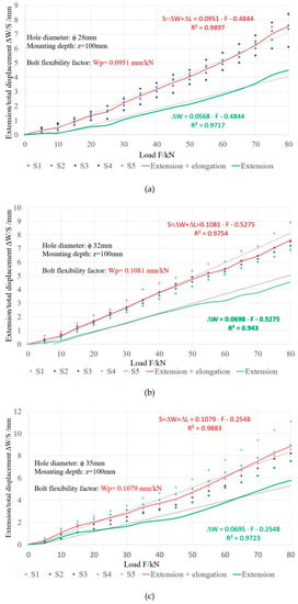

Figure 16.
Bolt extension from hole ΔW and the total displacements along with bolt elongation ΔL as functions of tensile load for the installing depth of 0.1 m and bolt hole diameters: (a) 0.028 m; (b) 0.032 m; (c) 0.035 m; (d) 0.037 m.
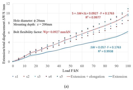
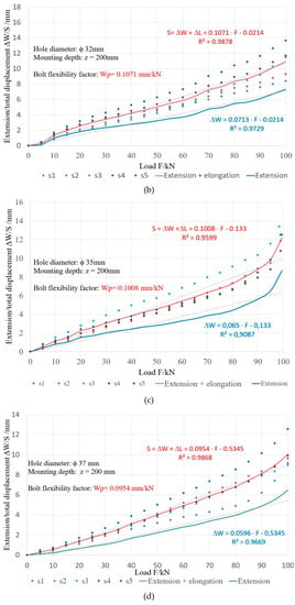
Figure 17.
Bolt extension from hole ΔW and the total displacements along with bolt elongation ΔL as functions of tensile load for the installing depth of 0.2 m and bolt hole diameters: (a) 0.028 m; (b) 0.032 m; (c) 0.035 m; (d) 0.037 m.
Steel bolt elongation occurs within the elastic range and equals:
where:
- ΔL—bolt elongation /mm,
- F—tensile force on the bolt /kN,
- L—bolt length minus the glue-in part /mm,
- d—bolt diameter /mm,
- E—steel elasticity modulus, E = 210 GPa.
Using Equation (6) to calculate bolt elongation ΔL, based on Equation (4) and the measured total displacement value S, we can calculate the value of the bolt’s extension from the hole ΔW. Figure 16a–d and Figure 17a–d illustrate the test and calculation results. Performing a linear approximation of the experimental data in Table 2 and Table 3, we obtained the following relationships:
S = ΔW + ΔL = Wp · F – c.

Table 2.
Functions describing the load and displacement properties of bolts for z = 0.1 m.

Table 3.
Functions describing the load and displacement properties of bolts for z = 0.2 m.
Slope Wp in Equation (7) is a bolt’s flexibility factor expressed by the ratio of the value of displacement increase to the value of axial tension increase (Figure 16a–d and Figure 17a–d).
Table 4 shows that the bolt’s extension from the hole constitutes about 63% of the total recorded bolt displacement (extension and elongation) at the measurement station. In addition, Table 4 shows the flexibility factors Wp for all tested hole diameters and installing depths. We show the relationships between the flexibility factor Wp1, involving both the bolt extension and strain (ΔW + ΔL) and only extension Wp2 (ΔW) (Table 4) and the bolt hole diameter (Figure 18). For the installing depth of z = 0.1 m, it was found that this factor grows along with the growth of the hole diameter, within the range 0.028 to 0.037 m. No similar relationship was found for bolts with an installation depth of 0.2 m, which might require extending the scope of testing in the future.

Table 4.
Bolt flexibility factor.

Figure 18.
Bolt flexibility factor Wp as a function of hole diameter d, with the installing depth of z = 0.1 m.
5. Conclusions
Room and pillar mining methods are commonly used in the underground mining of mineral deposits. The working area is secured by technological and remaining pillars and the roof bolting, independent or reinforced with a mesh and lines. The performance and effectiveness of the room and pillar mining method depend on the width of the opening of the working area, among other things. With the optimum dimensions of pillars and rooms, the stability of pits should be ensured with as high a rate of deposit recovery as possible, taking into account the number of support pillars. Based on numerical modeling, which accounted for the use of the room and pillar mining method for deposit excavation with two, three, and four rows of rooms, it can be concluded that the maximum ranges of the fault zone of rocks around pits differed only slightly, and the number of rows did not significantly affect its growth.
The load and displacement specifications, which were investigated under laboratory conditions for the Olkusz-16A roof bolting demonstrate that:
- The installation depth of 0.1 m made it possible to obtain the full specifications for the diameter of 0.032 m and maximum load-bearing capacity, 106.87 kN, was recorded.
- Increasing installation length to 0.2 m allowed us to prepare specifications for all four bolt hole diameters: 0.028 m; 0.032 m; 0.035 m; 0.037 m, until material discontinuity (the steel rod of the bolt at the diameter of the thread core) appeared.
- The maximum load-bearing capacities of the roof bolting with the increasing diameters of the bolt hole were: 103.17 kN, 111.40 kN, 99.55 kN, and 101.71 kN, respectively.
- For both 0.1 m and 0.2 m installation depths, the maximum load-bearing capacities were recorded for the diameter of 0.032 m.
- Glue-in roof bolting installed along 0.2 m for the bolt hole diameter of 0.032 m demonstrated the most favorable conditions for the joint operation of the roof bolting and the rock mass.
- The bolt’s extension from the hole during loading constitutes about 63% of the total recorded bolt displacement (extension and elongation) at the measurement station.
- For the installation depth of z = 0.1 m, it was found that this factor grows along with the growth of the hole diameter, within the range 0.028 to 0.037 m. No similar relationship was found for bolts with an installation depth of 0.2 m, which might require extending the scope of testing in the future.
Author Contributions
Conceptualization, K.S. and W.K.; methodology, K.S., W.K., and K.Z.; software, K.S.; validation, W.K.; formal analysis, K.S., W.K., K.Z., and A.Z; investigation, K.S., W.K., K.Z., and A.Z.; resources, K.S. and W.K.; writing—original draft preparation, K.S. and W.K.; writing—review and editing, K.S. and W.K.; visualization, K.S. and A.Z.; supervision, W.K.
Funding
Article prepared as part of AGH’s statutory work, under number: 11.11.100.005
Conflicts of Interest
The authors declare no conflict of interest.
References
- Skrzypkowski, K. A new design of support for burst-prone rock mass in underground ore mining. E3S Web Conf. 2018, 71. [Google Scholar] [CrossRef]
- Campbell, R.; Mould, R.J. Impacts of gloving and un-mixed resin in fully encapsulated roof bolts on geotechnical design assumptions and strata control in coal mines. Int. J. Coal Geol. 2005, 64, 116–125. [Google Scholar] [CrossRef]
- Canbulat, I.; Van der Merwe, J.N. Design of optimum roof support systems in South African collieries using a probabilistic design approach. J. S. Afr. Inst. Min. Metall. 2009, 108, 71–88. [Google Scholar]
- Zou, J.; Zhang, P. Analytical model of fully grouted bolts in pull-out tests and in situ rock masses. Int. J. Rock Mech. Min. 2019, 113, 278–294. [Google Scholar] [CrossRef]
- Skrzypkowski, K. Evaluation of Rock Bolt Support for Polish Hard Rock Mines. E3S Web Conf. 2018, 35. [Google Scholar] [CrossRef]
- Maepa, T.G.; Zvarivadza, T. Installation of resin-grouted rockbolts in hard rock mining:challenges and solutions for improved safety. J. S. Afr. Inst. Min. Metall. 2017, 117, 329–336. [Google Scholar] [CrossRef][Green Version]
- Skrzypkowski, K. Laboratory testing of a long expansion rock bolt support for energy-absorbing applications. E3S Web Conf. 2018, 29. [Google Scholar] [CrossRef]
- Villaescusa, E.; Varden, R.; Hassell, R. Quantifying the performance of resin anchored rock bolts in the Australian underground hard rock mining industry. Int. J. Rock Mech. Min. 2008, 45, 94–102. [Google Scholar] [CrossRef]
- Feng, X.; Zhang, N.; Li, G.; Guo, G. Pullout Test on Fully Grouted Bolt Sheathed by Different Length of Segmented Steel Tubes. Shock Vib. 2017, 2017, 4304190. [Google Scholar] [CrossRef]
- Korzeniowski, W.; Skrzypkowski, K.; Herezy, Ł. Laboratory method for evaluating the characteristics of expansion rock bolts subjected to axial tension. Arch. Min. Sci. 2015, 60, 209–224. [Google Scholar] [CrossRef]
- Marcon, M.; Vorel, J.; Nincevic, K.; Wan-Wendner, K. Modeling Adhesive Anchors in a Discrete Element Framework. Materials 2019, 10, 917. [Google Scholar] [CrossRef] [PubMed]
- Kılıc, A.; Yasar, E.; Celik, A.G. Effect of grout properties on the pull-out load capacity of fully grouted rock bolt. Tunn. Undergr. Space Technol. 2002, 17, 355–362. [Google Scholar] [CrossRef]
- Kılıc, A.; Yasar, E.; Atis, C.D. Effect of bar shape on the pull-out capacity of fully-grouted rockbolts. Tunn. Undergr. Space Technol. 2003, 18, 1–6. [Google Scholar] [CrossRef]
- Li, C.C.; Kristjansson, G.; Høien, A.H. Critical embedment length and bond strength of fully encapsulated rebar rockbolts. Tunn. Undergr. Space Technol. 2016, 59, 16–23. [Google Scholar] [CrossRef]
- Martín, L.B.; Tijani, M.; Hadj-Hassen, F.; Noiret, A. Assessment of the bolt-grout interface behaviour of fully grouted rockbolts from laboratory experiments under axial loads. Int. J. Rock Mech. Min. 2013, 63, 50–61. [Google Scholar] [CrossRef]
- Ma, S.; Nemcik, J.; Aziz, N. An analytical model of fully grouted rock bolts subjected to tensile load. Constr. Build. Mater. 2013, 49, 519–526. [Google Scholar] [CrossRef]
- Hagan, P.C. The effect of resin annulus on anchorage performance of fully encapsulated rockbolts. In Proceedings of the 10th Congress of the International Society of Rock Mechanics: ‘Technology Roadmap for Rock Mechanics’, Sandton, South Africa, 8–12 September 2003; International Society for Rock Mechanics: Lisbon, Portugal, 2003; pp. 113–118. [Google Scholar]
- Zhang, Y.; Ni, P. Design optimization of room and pillar mines: A case study of the Xianglushan tungsten mine. Q. J. Eng. Geol. Hydrogeol. 2018, 51, 352–364. [Google Scholar] [CrossRef]
- Zhou, Y.; Li, M.; Xu, X.; Li, X.; Ma, Y.; Ma, Z. Research on Catastrophic Pillar Instability in Room and Pillar Gypsum Mining. Sustainability 2018, 10, 3773. [Google Scholar] [CrossRef]
- Hudeček, V.; Šancer, J.; Zubíček, V.; Golasowký, J. Czech Republic. Experience in the adoption of Room & pillar mining method in the company OKD a.s., Czech Republic. Acta Montan Slovaca 2017, 22, 303–312. [Google Scholar] [CrossRef]
- Skrzypkowski, K. Compressibility of materials and backfilling mixtures with addition of solid wastes from flue-gas treatment and fly ashes. E3S Web Conf. 2018, 71. [Google Scholar] [CrossRef]
- Zhou, N.; Yan, H.; Jiang, S.; Sun, Q.; Ouyang, S. Stability Analysis of Surrounding Rock in Paste Backfill Recovery of Residual Room Pillars. Sustainability 2019, 11, 478. [Google Scholar] [CrossRef]
- Luo, Y. Room and pillar panel design method to avoid surface subsidence. Min. Eng.-Littleton 2015, 67, 105–110. [Google Scholar]
- Wagner, H. Deep Mining: A Rock Engineering Challenge. Rock Mech. Rock Eng. 2019, 52, 1417–1446. [Google Scholar] [CrossRef]
- Piechota, S. Technika Podziemnej Eksploatacji złóż rud (Techniques of Underground Mining of Ore Deposits); University Script No. 1129; AGH Publishing House: Kraków, Poland, 1998; p. 191. [Google Scholar]
- Rocscience. Available online: https://www.rocscience.com (accessed on 29 April 2019).
- Epstal. Available online: http://epstal.pl/en/reinforcing-steel/properties (accessed on 29 May 2019).
- PRIG. Available online: https://prig-kleje.pl (accessed on 29 May 2019).
- Skrzypkowski, K.; Korzeniowski, W.; Zagórski, K.; Dudek, P. Application of long expansion rock bolt support in the underground mines of Legnica-Głogów Copper District. Studia Geotechnica et Mechanica 2017, 39, 47–57. [Google Scholar] [CrossRef]
- Polish Standard: PN-G-15091. Requirements. Polish Committee for Standardization; Polish Committee for Standardization: Warszawa, Poland, 1998.
© 2019 by the authors. Licensee MDPI, Basel, Switzerland. This article is an open access article distributed under the terms and conditions of the Creative Commons Attribution (CC BY) license (http://creativecommons.org/licenses/by/4.0/).