Article

Surface Microtexture Fabrication and Temperature Gradient Regulation of Micro Wankel Engine

1
Key Laboratory of Fundamental Science for Advanced Machining, Beijing Institute of Technology, Beijing 100081, China
2
School of Mechanical Engineering, Beijing Institute of Technology, Beijing 100081, China
*
Author to whom correspondence should be addressed.
Energies 2019, 12(19), 3725; https://doi.org/10.3390/en12193725
Submission received: 21 August 2019 / Revised: 19 September 2019 / Accepted: 26 September 2019 / Published: 29 September 2019

Abstract

:
Nowadays, micro engine miniaturization is one of the most challenging issues, especially for the design and fabrication of the high-power-density micro Wankel engine. With the decrease of the size of the micro engine, the problem of the heat deformation of the cylinder becomes more serious. In this paper, a micro Wankel engine with microtextures on the outer surface of the cylinder is designed and manufactured to diffuse the heat dissipation and regulate the temperature gradient, so as to increase the power output density. First, a series of finite element simulations are conducted to design a type of ideal surface microtexture. Then, the machining condition is optimized to fabricate microtextures by micro cutting on the cylinder surface by studying the processing parameters. Finally, the performance of the new micro Wankel engine in terms of the temperature gradient regulation and the mechanical power output is tested and compared with that of the un-textured micro engine. The comparison results show that temperature of the textured micro engine was dropped from 185 °C to 125 °C and the mechanical power output increased by 10.74% from that of its un-textured counterpart, verifying the proposed methods for temperature gradient regulation.

Graphical Abstract

1. Introduction

Micro Wankel engines are a key part of unmanned aerial vehicles (UAVs) because of their high energy density output for high speed cruising. However, with the decrease in the size of micro- Wankel engines, the thermal stress within the Wankel engine cylinder becomes overloaded and the structure deformation becomes more serious. Normally, the micro Wankel engine experiences four processes during operation: inhalation, compression, expansion and exhaust. The fuel undergoes combustion and expansion in the combustion chamber to generate a large amount of heat, but the heat dissipation is hindered because of the decrease of the cylinder size. The heat generated during the operation causes a significant difference in the stress of both the cylinder and cover. Furthermore, the excessive stress leads to unwanted deformation of the parts resulting in low chamber tightness. As a result, the overall performance of the micro Wankel engine is deteriorated. A number of methods have been implemented and studied to improve the performance of the micro- engine.
The mechanical power output is one of the most important factors to evaluate the performance of the micro engine. Most researchers focus on developing powerful fuels to improve engine efficiency. Ehsanollah et al. [1] and Balli et al. [2] have developed some novel fuels, increasing the engine power output by 21% and 6.3%, respectively. Gonca et al. [3] proposed combining the application of the Miller cycle and turbo charging together into a diesel engine. The torque, effective power, and effective efficiency are considerably improved by applying this particular modification. Fang et al. [4] have shown that the performance properties of the pneumatic prototype engine are improved by using heat supply during the operation, which is 22% higher than that of the traditional engine.
Some researchers have paid attention to generating microtextures on the engine surface to reduce the friction on the interfaces, and improve power output. Shark-skin-inspired surfaces for aircraft applications have been researched by National Aeronautics and Space Administration (NASA) [5] as well as the German Aerospace Center [6]. Zhang and Bijay [7] designed a kind of microtextured surface to facilitate drag reduction, and the results show that the blade with microtexture has a remarkable effect in lowering friction on the aero engine. In this paper, we proposed a novel method to improve the temperature gradient regulation and mechanical power output. However, if the microtextures are fabricated with low accuracy, the performance of the microtextured surface may function far below the design expectation. The processing techniques of microtextures include etching, micro electric discharge machining, wire EDM and micro cutting. Gollasch et al. [8] revealed that the optical microcavities can be manufactured by etching on atom chips, but the complicated technological process and high manufacturing cost make it difficult to promote. Chen et al. [9] worked out 15 μm microtexture in sheet metal using 13 μm electrode, though the electrode is easily eroded and the machined surface has a low quality. Zhengkai Li et al. [10] carried that array of 256 (2 × 128) micro-holes with average diameter of 46.13 μm using micro EDM, but there are many burrs on the micro-holes. Kobayashi et al. [11] carried out V-shape groove in amorphous Ni-P alloy using ultra-precision machining technology. Among these techniques, micro cutting is the most efficient way to produce various microtextures.
Finite element simulation is an effective way to study the micro cutting process of various materials and the material constitutive as a key to establish a model for finite element method (FEM) simulation. The Johnson–Cook (JC) model is one of the most popular models for describing the material behavior under large strain and high strain rate because of its simple expression and material constants [12,13]. However, it fails to accurately describe the material property in high-speed machining because it neglects the coupling effect of strain, strain rate, temperature, strain softening effect and size effect [14]. Che et al. [15] introduced an integrated Johnson–Cook and Zerilli–Armstrong (ZA) model, which takes into consideration the coupling effects of strain, strain rate and temperature. Calamaz et al. [16] proposed an improved JC model that considers the strain softening effect by introducing the THAN model for the machining of titanium alloy Ti-6Al-4V. Lai et al. [17] explained the size effect in micro scale milling by introducing mechanism-based strain gradient plasticity (MSG).
In order to accurately create microtextures according to the design on the outer surface of the cylinder, the experiments and simulations are conducted in light of the coupling effects of the strain, strain rate, temperature, and strain softening effect to optimize the micro cutting condition. Finally, the performances in term of temperature gradient regulation and mechanical power output of the un-textured and textured micro engine are tested and compared, showing that fabricating microtextures on the outer surface of the cylinder is an effective method to improve the mechanical power output of the micro engine.

2. Simulations on Micro Cutting of Microtextures

2.1. Material Behaviors Modeling

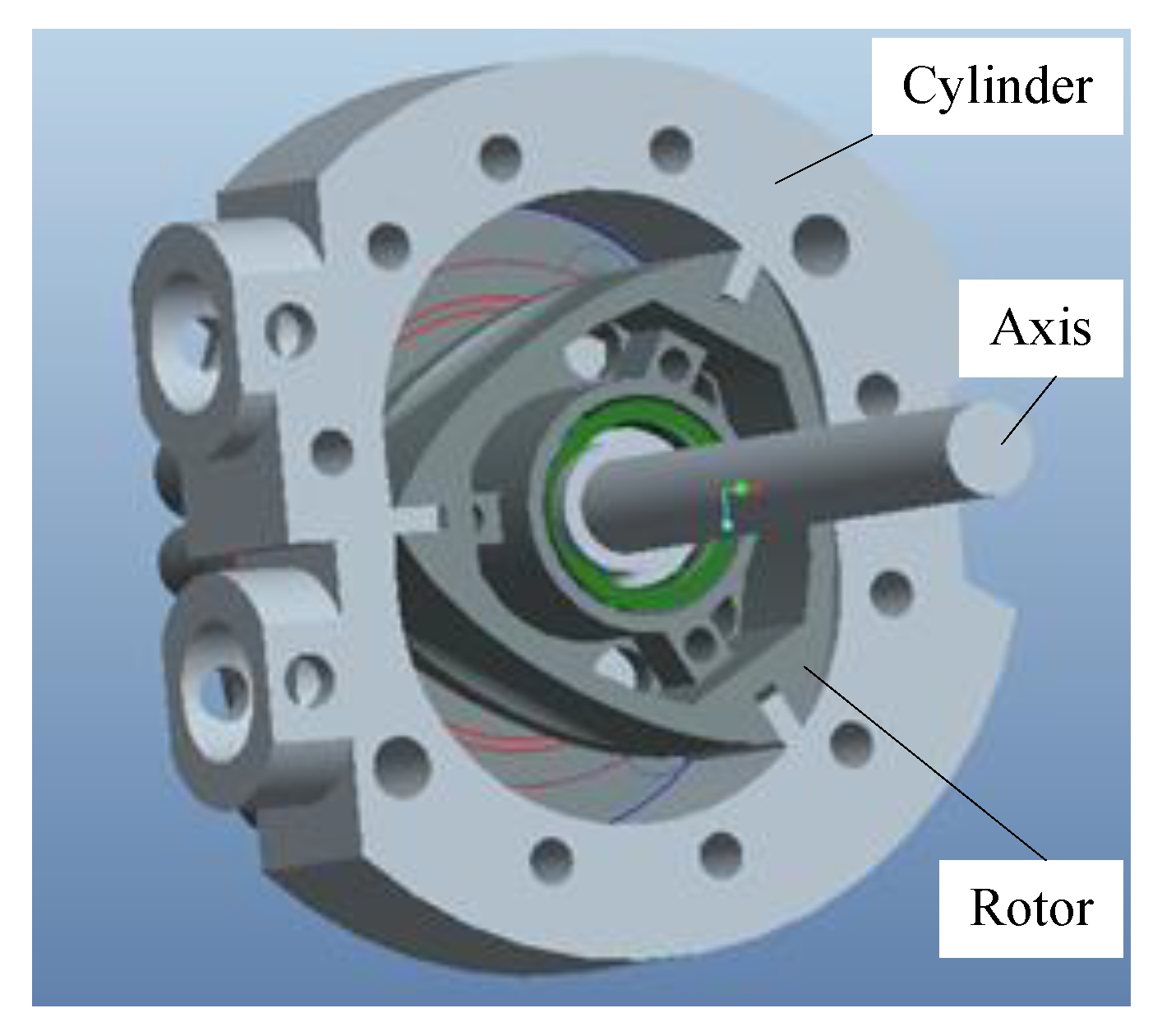
The structure of the Wankel engine is shown in Figure 1. The main parts are cylinder, axis and rotor. In this paper, the cylinder would be researched in order to regulate the temperature gradient and improve the mechanical power output. The material of cylinder is Ti-6Al-4V.
In the high-speed machining of Ti-6Al-4V alloy, the flow stress decreases with the increase of strain, which is termed the work softening phenomenon. Based on the previous research, a constitutive model combining the JC model [13], ZA model [18] and THAN model [16], was proposed by our research team. The flow stress is expressed as
σ n o v e l = [ A + B ε n ( 1 exp ( ε a ) ) ] exp { ( C 1 + C 2 ε ) T + ( C 3 + C 4 T ) ln ε ˙ } [ D + ( 1 D ) [ tanh ( 1 ( ε + p ) r ) ] s ]

2.2. Material Properties

The physical property of Ti-6Al-4V alloy material is fundamental in calculating the formula parameters in the model. The principle chemical composition of experimental Ti-6Al-4V alloy by EDX analysis is shown in Table 1.
The element contents of the Ti-6Al-4V alloy determine the material mechanical properties, such as the yield strength, tensile strength, and breaking strength. Normally, the parameters of the material properties, such as the Young’s modulus (E), expansion (α), conductivity (λ) and specific heat (Cp) are considered as constants. In fact, they are functions of temperature. Table 2 shows the thermal and mechanical properties of Ti-6Al-4V with respect to temperature [19].

2.3. Simulation on Temperature Gradient and Deformation

Microtextures on cylinder surface can improve the performance of micro engine, but this performance improvement effect is up to the rib width. Therefore it is necessary to analyze the temperature gradient and deformation performance of cylinder with different rib widths to determine the perfect micro cutting parameters. In this section a series of simulations are conducted to discuss the influence of the microtexture on temperature gradient regulation and deformation.
The rib width is determined as 100 μm, 50 μm and 20 μm, respectively. It can be concluded from the calculation that the number of ribs is 3, 4 and 5 respectively. The finite element simulation model is used to establish the relationship between the cylinder temperature gradient and rib width.
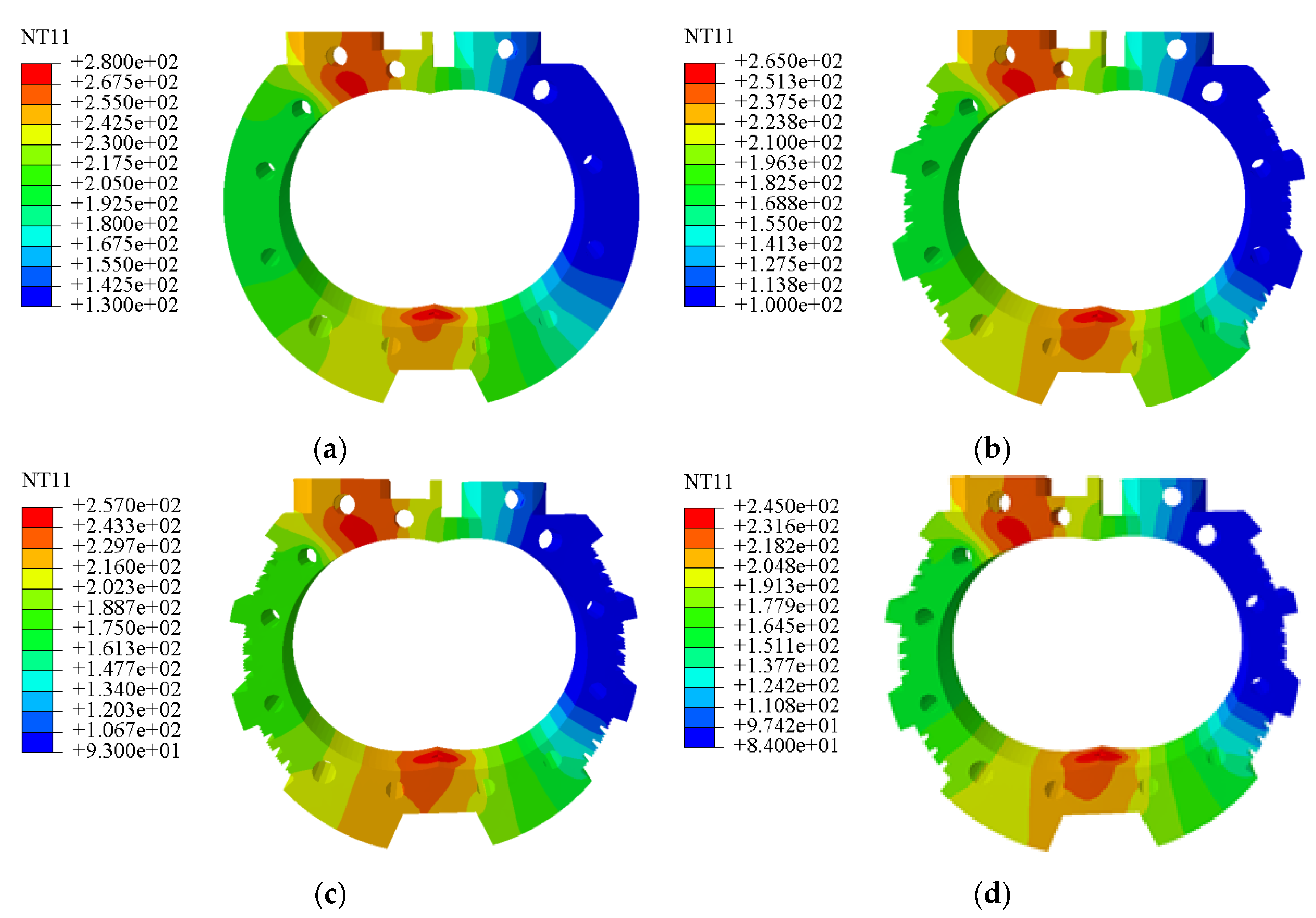
The highest temperature occurs in the gas combustion and expansion phase on the microtexture-free cylinder—corresponding to the position where the maximum heat transfer coefficient occurs—and the value reaches 280 °C. The lowest temperature occurs at the end of the heat sink at the intake stage—corresponding to the position where the minimum heat transfer coefficient occurs—and the value is 130 °C, as shown as Figure 2a. The machined microtexture on the outer surface of the cylinder causes the temperature of the entire cylinder to drop. When the rib width is 100 μm, the maximum temperature of the cylinder is 265 °C, and the lowest temperature is 100 °C, as presented in Figure 2b. When the rib width is 50 μm, the maximum temperature of the cylinder is 257 °C, and the lowest temperature is 93 °C, as shown in Figure 2c. When the rib width is 20 μm, the maximum temperature of the cylinder is 245 °C, and the lowest temperature is 84 °C, as presented in Figure 2d. The results are shown in Table 3.
By processing the microtexture on the outer surface of the cylinder, the overall temperature field of the cylinder is lowered, but the original temperature gradient of the temperature field in the cylinder is not affected. The heat dissipation performance of the cylinder is obviously improved, as well as the power output and life of the micro engine. The smaller the rib width is, the better the regulation of the temperature gradient of the cylinder.
During the operation of the micro engine, a hot zone and a cold zone will be formed in the combustion chamber. The excessive difference in temperature causes the cylinder to become unevenly deformed, affecting the stability of the micro engine. Therefore, it is necessary to study the influence of the microtexture on the cylinder deformation.
As shown in Figure 3a, the maximum deformation is 4.014 mm when the cylinder is manufactured without microtexture. When the rib width is 100 μm, the maximum deformation is 0.4428 mm, as shown in Figure 3b. When the rib width is 50 μm, the maximum deformation is 0.2031 mm, as shown in Figure 3c. As shown in Figure 3d, the maximum deformation is 0.0641 mm when the rib width is 20 μm.
Since the microtexture is processed on the outer surface of the cylinder, the regulation of the temperature gradient in the cylinder is improved, and the overall temperature field in the cylinder is reduced, correspondingly reducing the deformation caused by the temperature gradient of the cylinder. Remarkably, the textured cylinder with the best temperature gradient regulation, the stability of the cylinder cavity and the micro engine operation can be improved.
Through the analysis of temperature gradient and deformation, it can be determined that processing microtextures on the outer surface of the cylinder can regulate the heat gradient and reduce the deformation. When the rib width was decreased, the heat gradient regulation improved and the deformation decreased. Therefore, it is important to determine the most suitable size of the rib width.
As shown in Figure 4, the results of simulations with different rib widths are shown in order to determine the minimum rib width. The stress concentration point appears at the bottom of the groove edge and the maximum Mises stress equals approximately 1000 MPa when the rib width equals 10 μm, which is larger than the yield limit of titanium alloy [20]. There is no stress concentration point at the bottom of the groove edge when the rib width equals 20 μm. Therefore, the most suitable rib width is 20 μm.

3. Microtexture Manufacture

3.1. Mechanism of Microtexture Processing

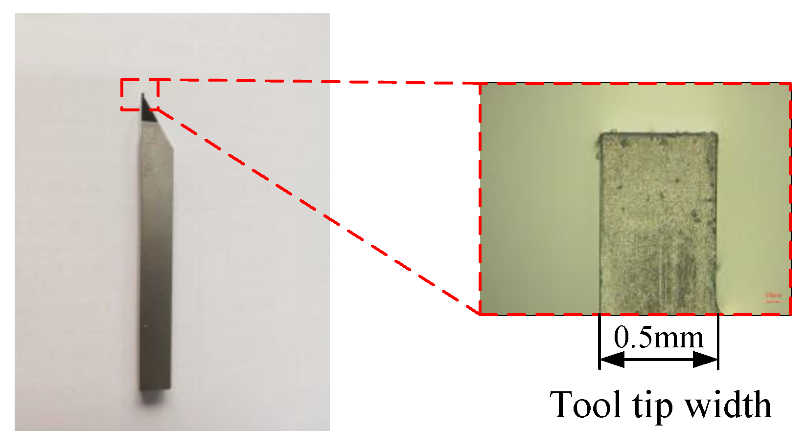
In order to study the processing mechanism of microtexture, experiments with different rib widths are conducted. The experimental setup of the machining center and the cubic boron nitride (CBN) cutting tool are shown in Figure 5 and Figure 6, respectively. The parameters of the micro cutting tool are exhibited in Table 4. The micro cutting parameters are shown in Table 5.
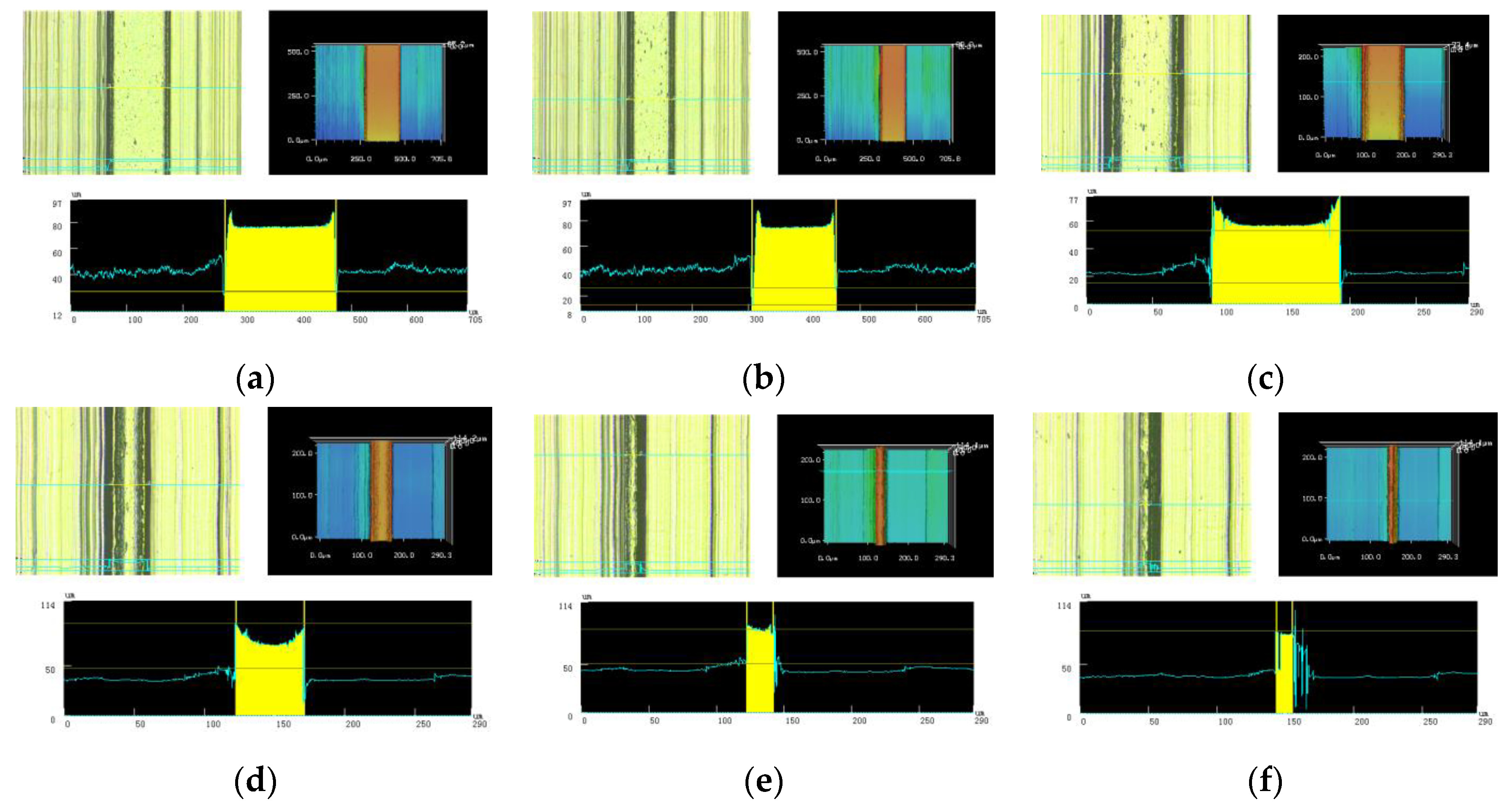
Figure 7a,b are microscope photographs of the microtextures with the widths of 200 μm and 150 μm, respectively. From the results of Figure 7c–e, it can be concluded that the accuracy can still be maintained when the range of rib width is among 100 μm and 20 μm. However, when the rib width is 10 μm, the shape of the rib has been deformed, which is brought on by the minimum cutting thickness [21], and the defect on the right side of the rib has affected the precision of the width, decreasing the quality of the rib, making it unable to satisfy the processing requirements. The result of the most suitable rib width in micro cutting experiments and simulations shows a close match.
Ti-6Al-4V titanium alloy is an elastoplastic material. Based on the principle of minimum cutting thickness, when the stress is less than the yield strength of the material, the material only deforms elastically, and the slight plastic deformation can be restored to the original state. At this time, the tool scratches the material instead of shearing it. When the rib width is 10 μm, the strength is insufficient on account of the narrow ribs, and the material is squeezed to the left side by the micro cutting of the cutting tool. When the cutting tool passes, some of the material returns to its original position, resulting in an excess and parabolic material on the right side of the rib as can be seen in Figure 7f.
In order to ensure the quality of the ridge width at 20 μm, the influence of different feeds on the quality of microtextures has to be studied, and the optimal feed that can control the microtexture quality is determined. The micro cutting parameters are shown in Table 6.
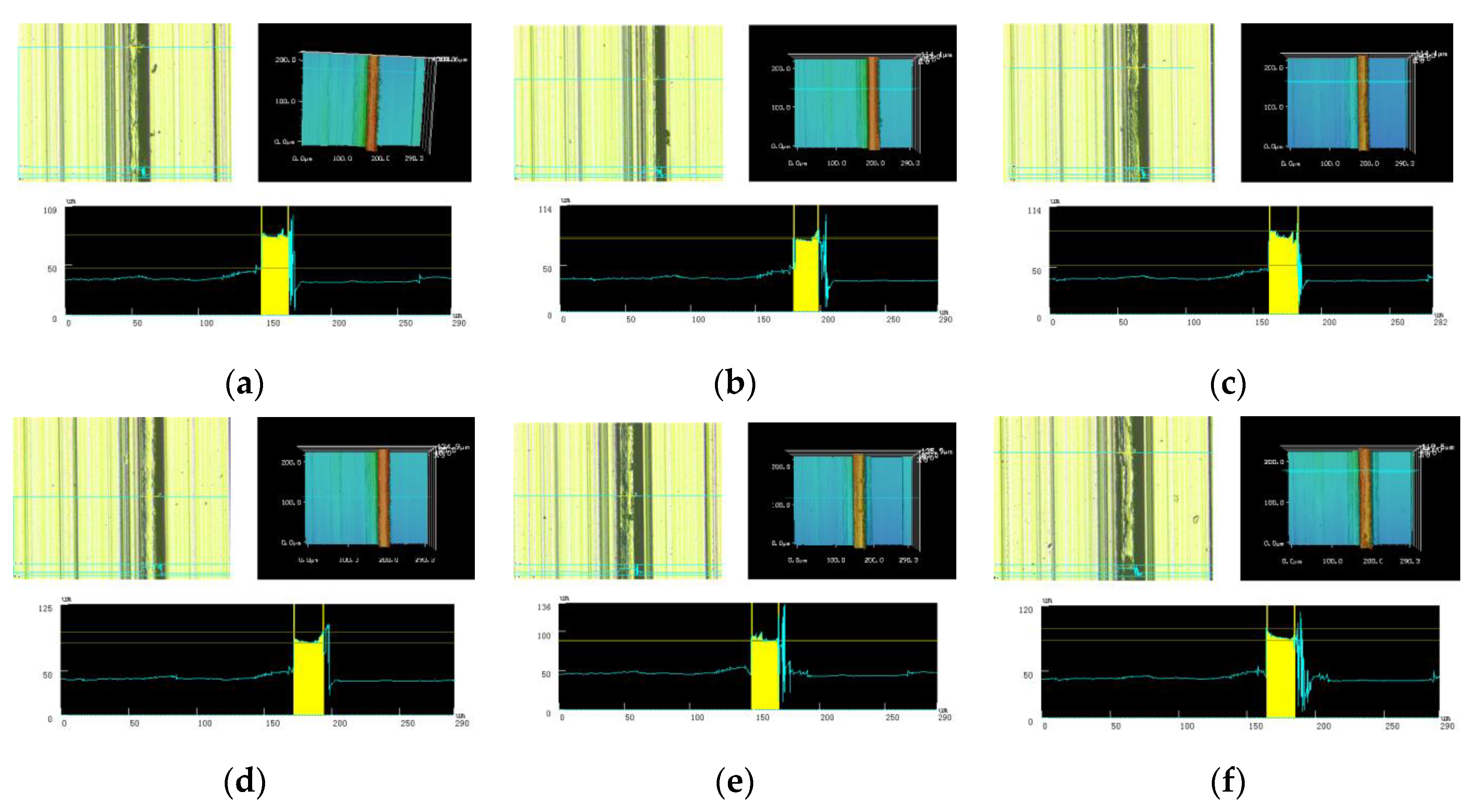
From the comparison of the topography in the case of the different feeds, it can be determined that at low feed (2 μm/r, 4 μm/r) and high feed (10 μm/r, 12 μm/r), an irregular defect appeared on the right side of the rib, and the precision of the rib width at 20 μm could not be well controlled.
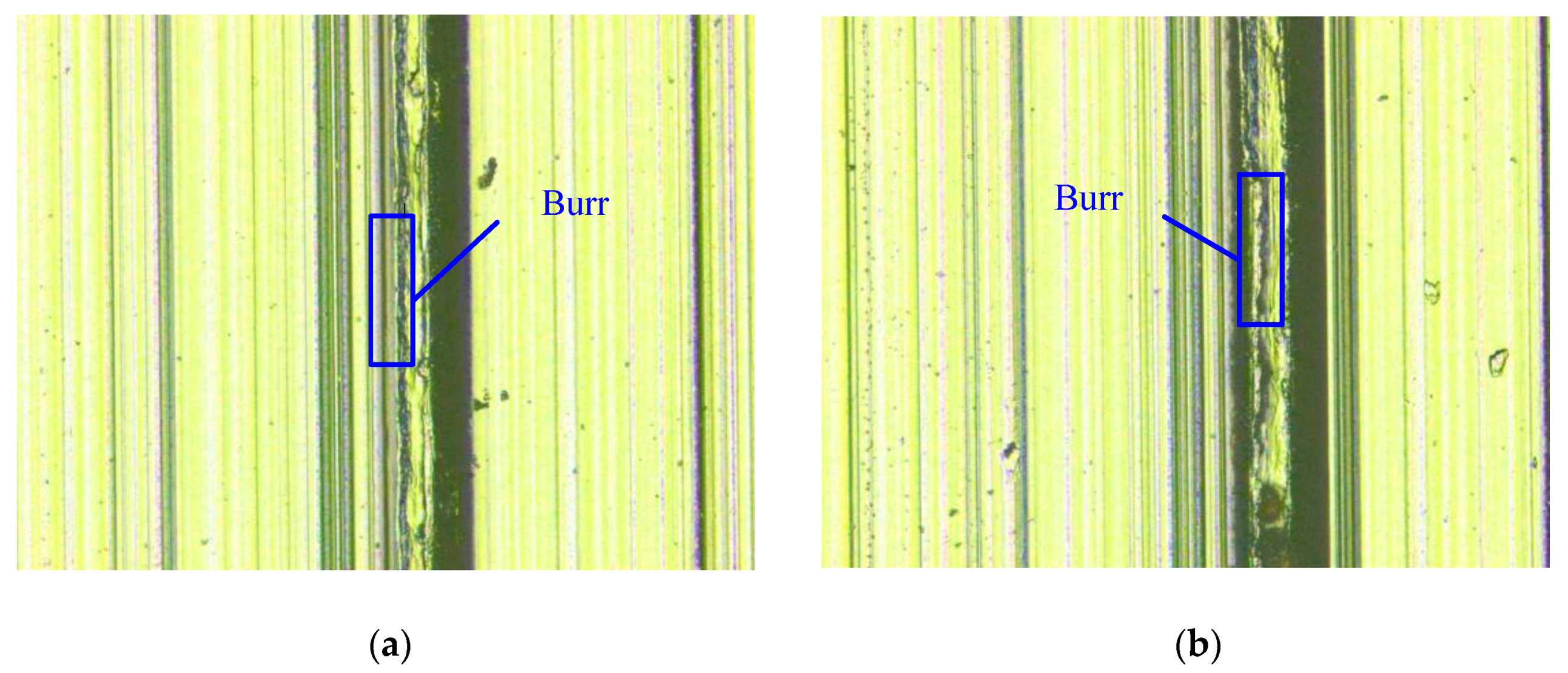
At the critical minimum cutting thickness, the extrusion deformation resulted from the elastic deformation of the material, although shear failure also occurs. As shown in Figure 8a,b, the smaller the cutting depth is, the more obvious the rebound is. With the decreasing of the feed, the extrusion deformation accompanying the material during shear failure is also more pronounced. When the feed is increased, the material flows up the side after the cutting tool is squeezed during manufacturing; eventually burrs would form on the edge of the ribs, as shown in Figure 8e,f. Moreover, with the increase in feed, the burr on the edge is more obvious, as shown in Figure 9. When the feed rate increase, the workpiece across the tool rake face with further velocity. It is well known that the cutting velocity is the most significant factor influencing tool wear. Therefore, further tool wear may cause plowing action instead of that, resulting in larger burr size in both the height and thickness directions. On the other hand, according to definition of the burr formation, each operation that eases the plastic deformation may increase the probability of burr formation. Thus, as the spindle speed increases, the cutting temperature in the tool–work interface also increases, resulting in less flow stress during machining [22]. When the feed equals 6 μm/r or 8 μm/r, both the effect of material removal and the formation of burrs can be controlled, resulting in a high quality of rib, as exhibited in Figure 8c,d. When the feed is 6 μm/r, the surface roughness Ra equals 0.607 μm, and when the feed is 8 μm/r, the surface roughness Ra equals 1.072 μm. Therefore, the most suitable feed is 6 μm/r.
In order to study the influence of micro cutting speed on the precision of the microtextures, a series of experiments at different rotation speeds was conducted. The micro cutting parameters are shown in Table 7.
At lower rotation speeds (1000 r/min and 1500 r/min), the material on the edge of the ribs will flow up the side of the cutting tool and form small burrs, caused by the viscoelastic properties of the Ti-6Al-4V titanium alloy material, as shown in Figure 10a,b. At higher speeds (2500 r/min and 3000 r/min), owing to the short time the material does not flow sufficiently during the process, resulting in the formation of chip on the outside of the edge, leading to a larger rib width as shown in Figure 10d,e. When the rotation speed equals 2000 r/min as shown in Figure 10c, the material outside the edges is satisfactorily removed and the chips are discharged, resulting in a perfect rib width.
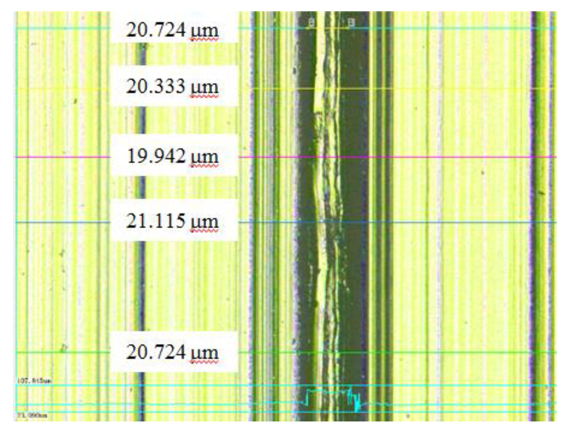
In order to ensure the consistency of rib width, five positions are selected randomly on the rib, where the width of the processed rib is measured as shown in Figure 11. The measurement results are 20.724 μm, 20.333 μm, 19.942 μm, 21.115 μm and 20.724 μm, respectively, where the accuracy of rib width is controlled from 0.29% to 5.58%. The accuracy of rib width can be appropriately controlled.
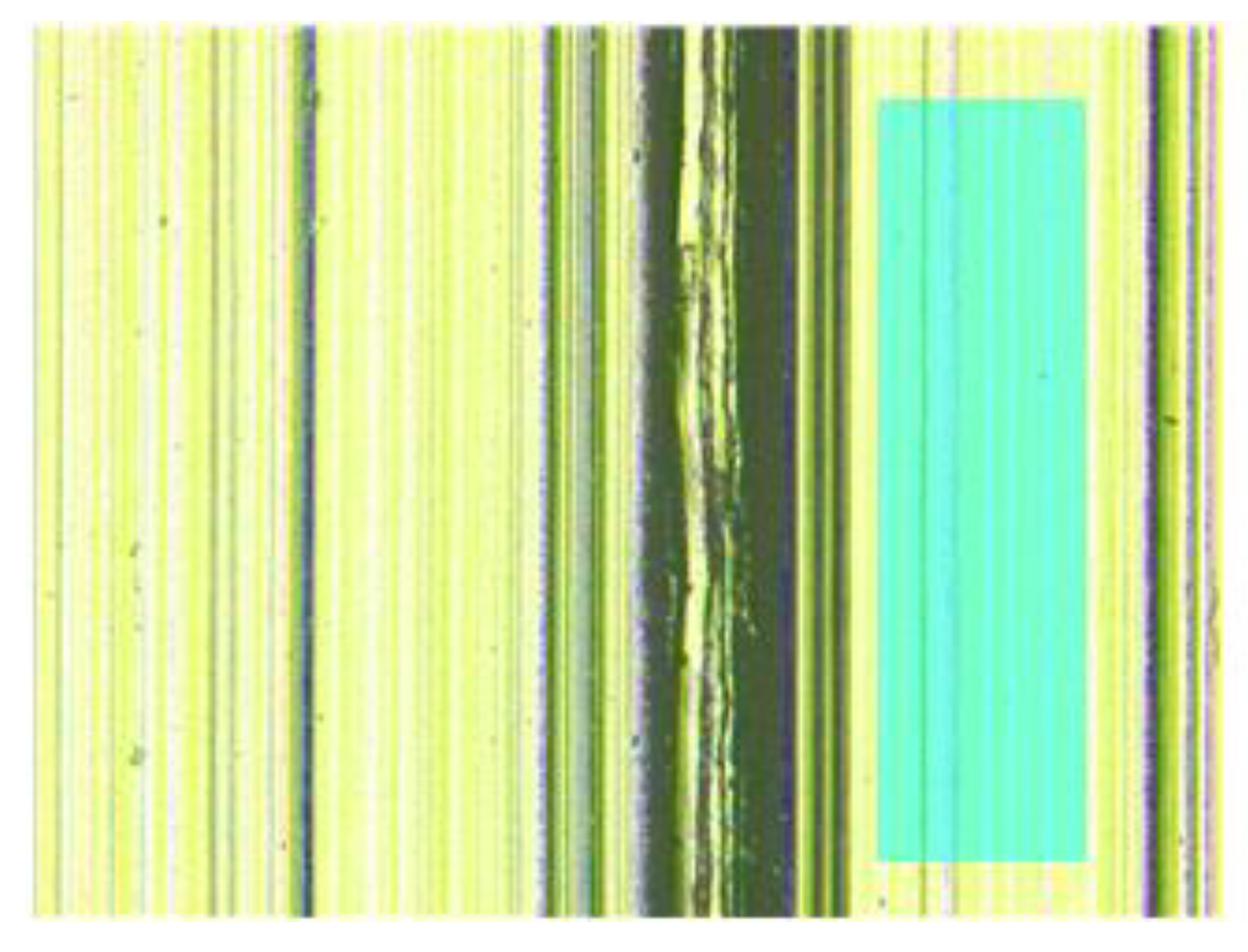
In addition to ensuring the accuracy of the rib width, the surface roughness of the microtexture is also an important indicator for evaluating the optimal micro cutting parameters. As shown in Figure 12, the surface roughness of the microtexture was measured at 2000 r/min. The surface roughness of the bottom of the entire microtexture is 0.495 μm, and the best local area can reach Ra 0.046 μm, having a high precision.
Through the above analysis, the optimal micro cutting parameters capable of processing the rib and the optimal microtexture surface quality can be obtained. The optimal micro cutting parameters are presented in Table 8.
3.2. Manufacture of Microtexture on the Cylinder Outer Surface

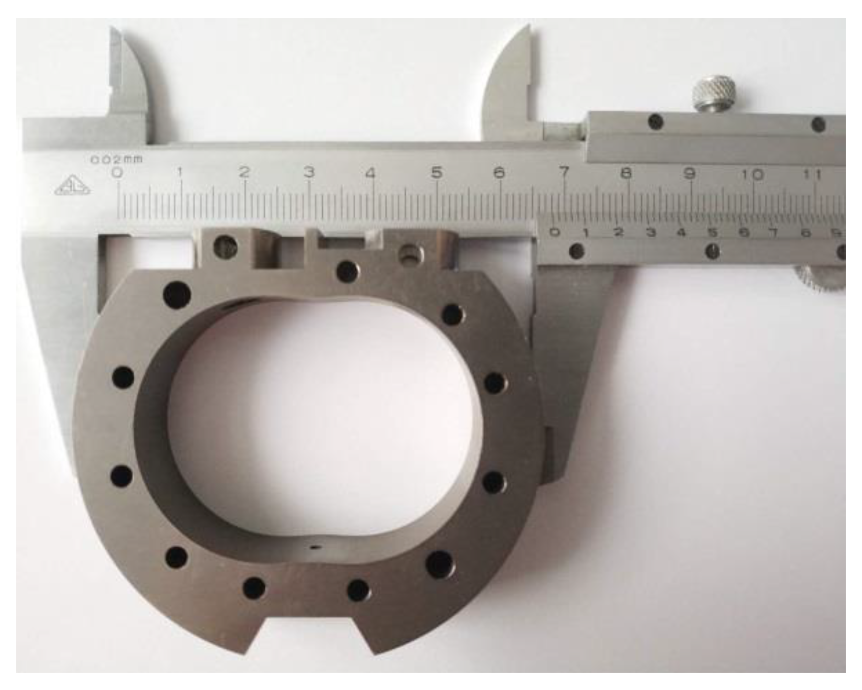
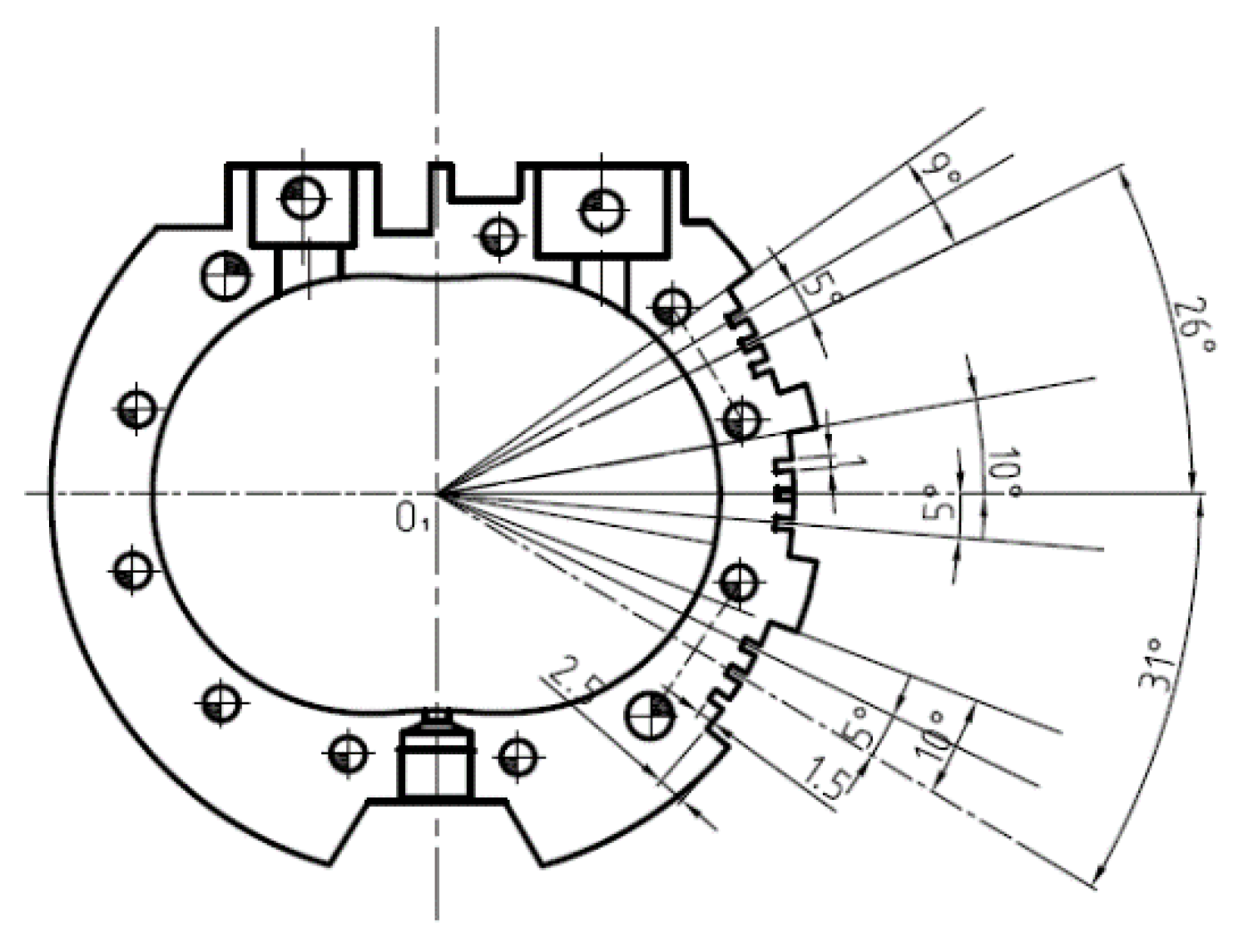
The outer surface of the cylinder can be obtained by the precision turning process. The cavity of the cylinder can be obtained by the precision milling process. The precision drilling process can provide the size and position of the positioning hole, and the cylinder is shown in Figure 13. The cylinder with microtextures is designed as can be observed in Figure 14.
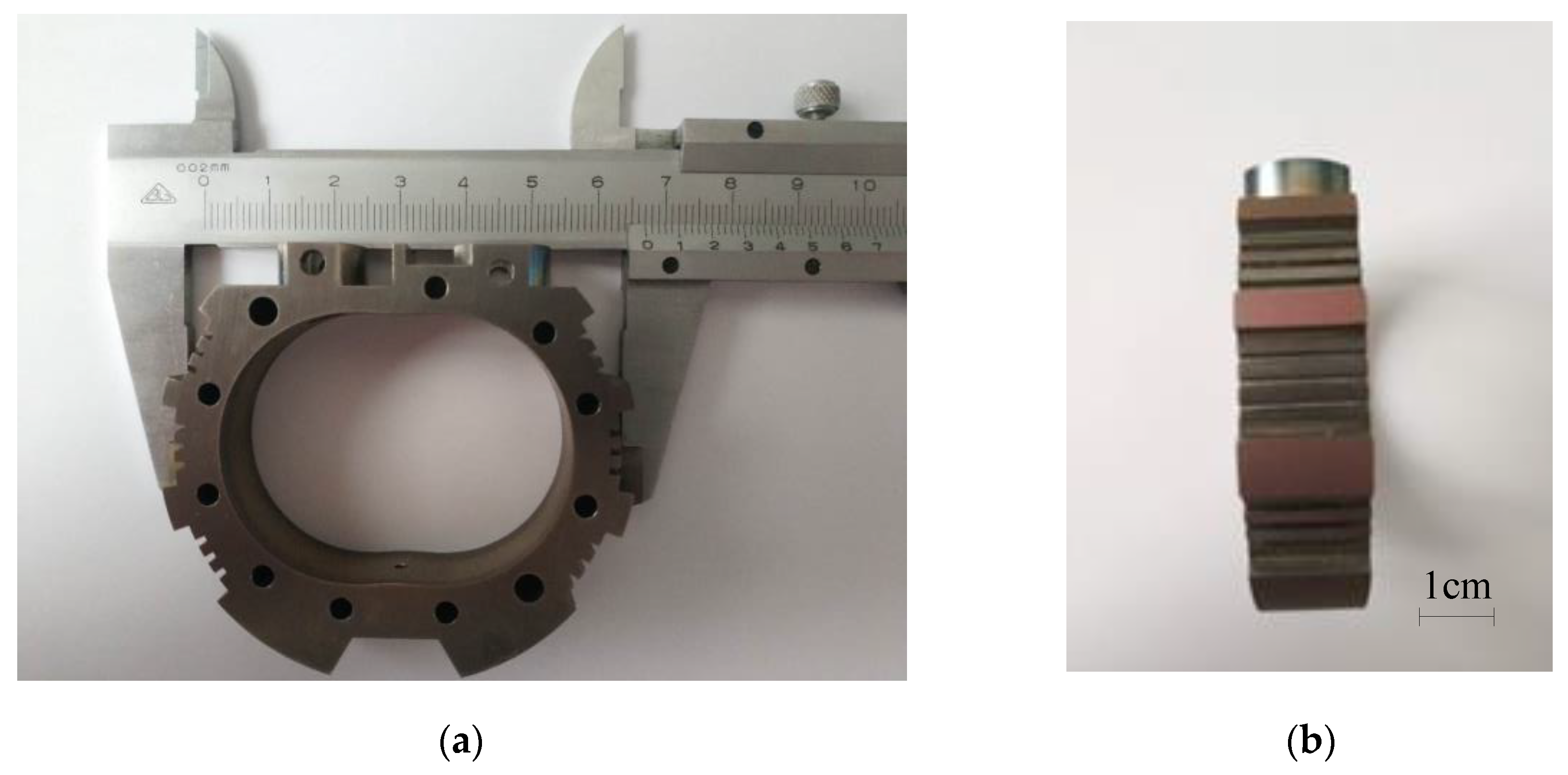
The final machined cylinder with microtextures as shown in Figure 15.
The microtextures were manufactured by the ultra-precision machining center and observed under microscope. The results are shown in Figure 16. The surface roughness on both sides of the rib is Ra 1.678 μm and Ra 1.318 μm, respectively, meeting the requirement of the regulation of temperature gradient of the cylinder.

4. Micro Wankel Engine Performance Test

4.1. Temperature Gradient Regulation Test

In order to study the influence of microtextures on the temperature gradient regulation of the cylinder, the temperature of the engine during its operation was measured, as can be observed in Figure 17.
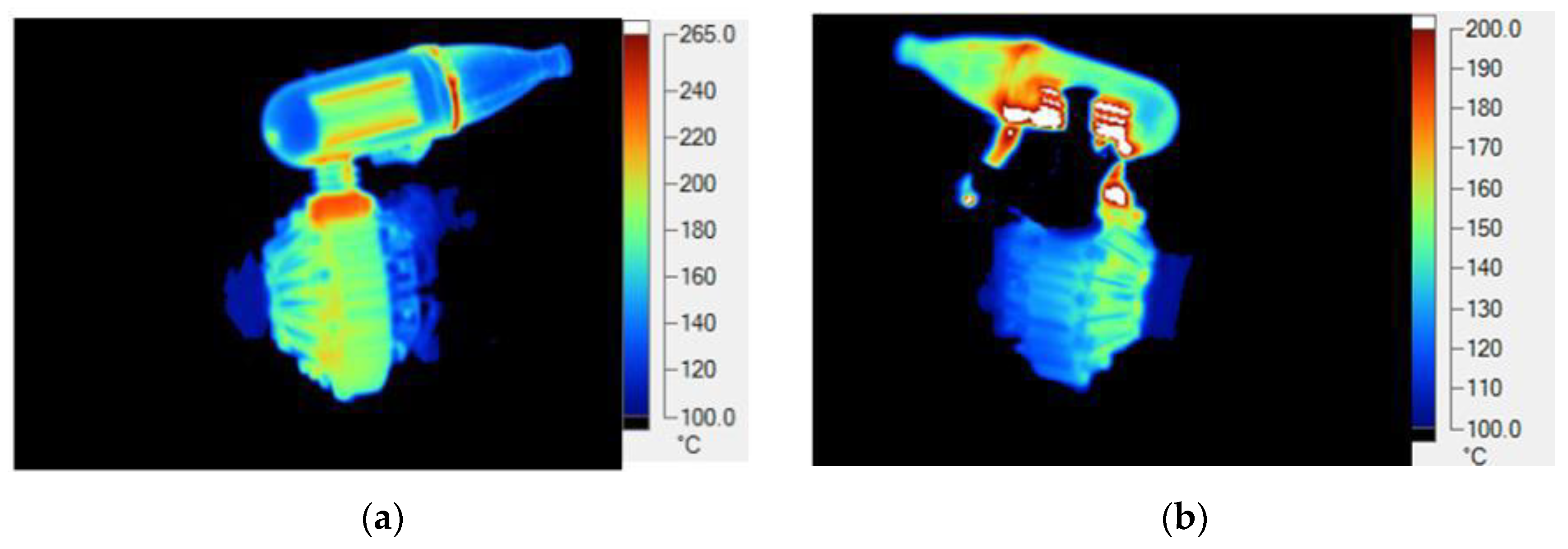
In the measurement, the emissivity is calibrated to reduce the error. As shown in Figure 18, the heat distribution of the micro Wankel engine is measured.
From the test result of the micro Wankel engine without microtextures, the maximum temperature of the overall engine is 265 °C, and the average temperature of the outer surface of the cylinder was 185 °C, as presented in Figure 18a. From the test result of the micro Wankel engine with microtextures, the maximum temperature of the overall structure was 200 °C, dropped by 65 °C, while the average temperature of the outer surface of the cylinder was 125 °C, which was dropped by 60 °C, as shown in Figure 18b. The results are shown in Table 9. The surface microtextures increase the heat dissipation area. The temperature gradient of the cylinder significantly dropped, and the temperature field on the end cover has also decreased, indicating that manufactured microtextures on the outer surface of the cylinder is a suitable way to regulate the temperature gradient.

4.2. Mechanical Power Output Test

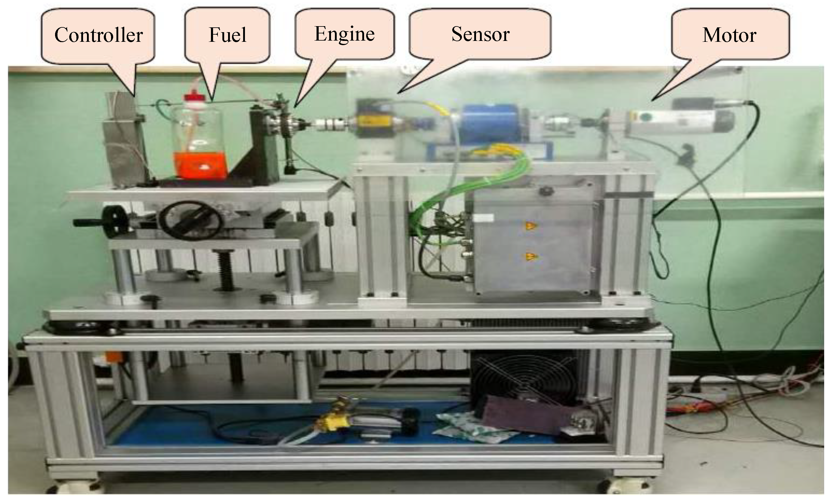
The micro Wankel engine is mainly composed of four parts: cylinder, rotor, end cover and eccentric shaft. These parts are assembled for the engine performance test, which includes testing intake airflow, temperature, speed, torque, fuel consumption, power as well as other parameters. As shown in Figure 19, the test platform mainly consists of five parts: the throttle control part, fuel, engine, torque sensor and drive motor. The motor is CH075016/R. In order to ensure timely disconnection between the engine and the motor after the engine is started, the test system is equipped with an electromagnetic clutch.
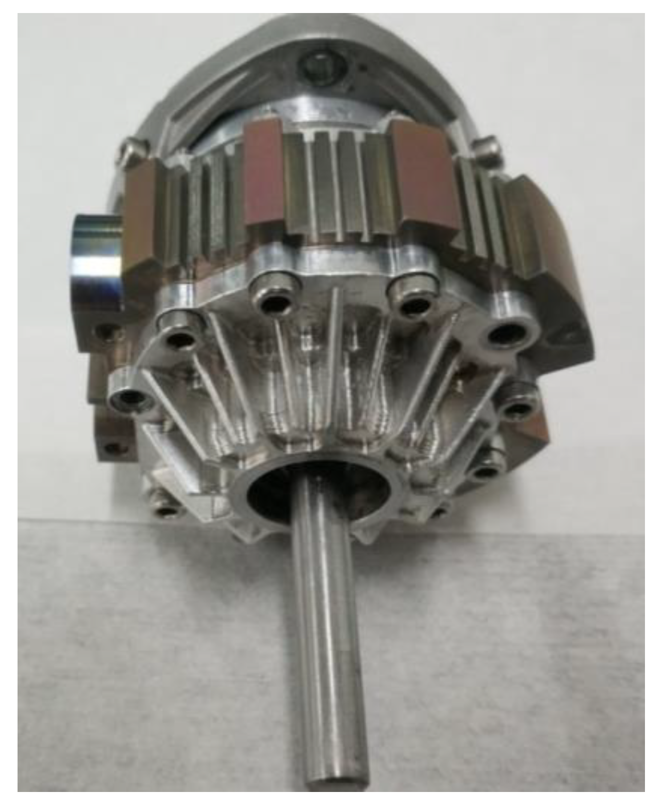
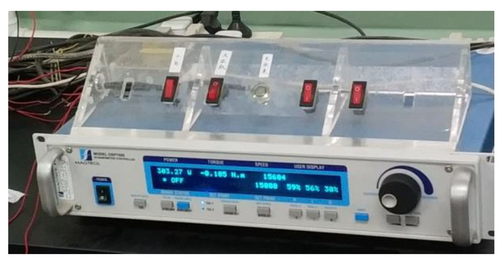
The micro Wankel engine was assembled like that seen in Figure 20. During the mechanical power output test of the engine, the controller controls the rotation of the drive motor, and the micro engine rotates through the coupling. When the engine reaches a steady speed, a flexible coupling separates the dynamometer and the drive motor. The methanol fuel is burned in the cylinder through the ignition device, and the experimental data of the generated rotational speed and torque is displayed on the data collector through the dynamometer sensor. The dynamometer is 4WB2.7-8-K, the maximum measuring speed is 50,000 rpm, and the maximum test power is 1 kW. The dynamometer system is equipped with a DSP7000 control system. The tester is shown in Figure 21.
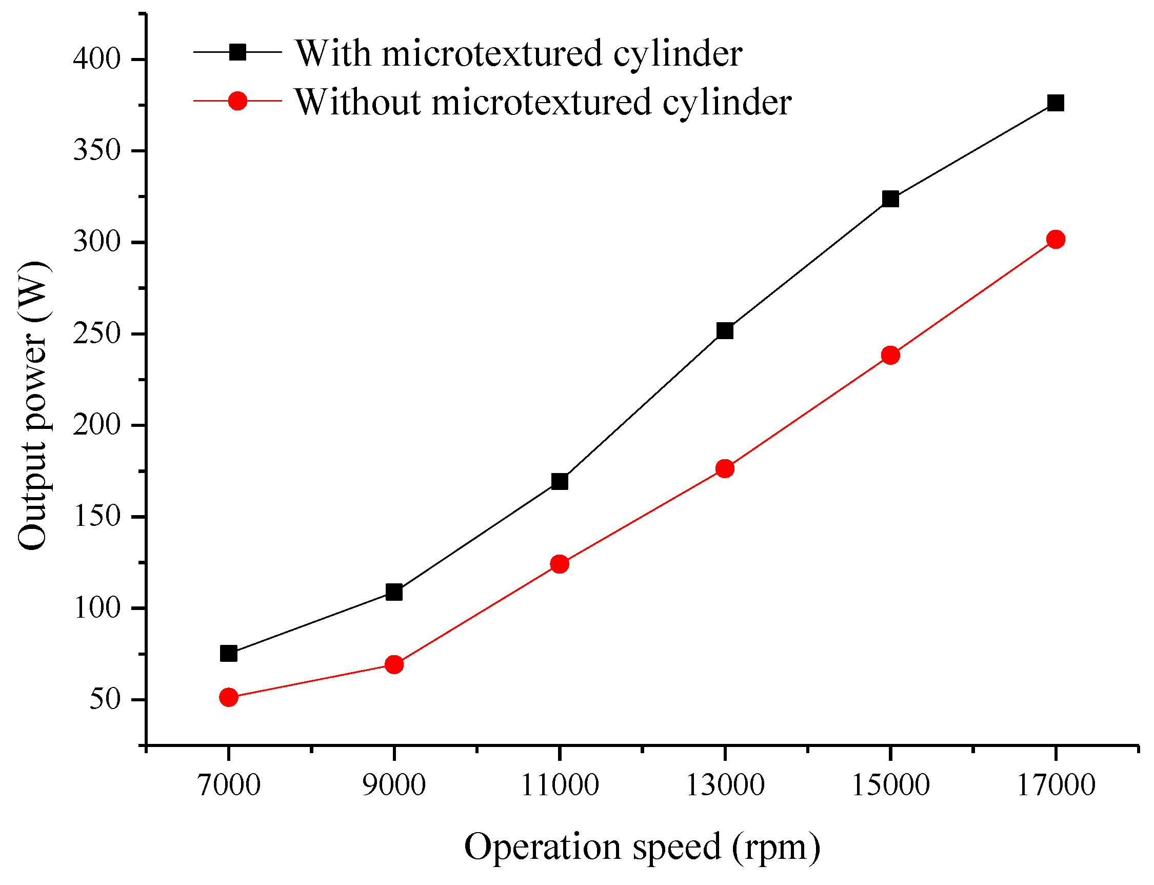
The output power at different operation speeds of Wankel engine with the microtextured cylinder and without microtextured cylinder are measured. The results are shown in Figure 22.

5. Conclusions

Experiments and simulations were conducted to study the surface microtextures fabrication and temperature gradient regulation of the micro Wankel engine for performance improvement. The following conclusions can be drawn:
(1)
Through a series of simulations, the temperature gradient and the deformation are both regulated by creating microtextures on the cylinder surface. The smaller the microtextures are, the more significant the regulation effect is.
(2)
Through a series of experiments that took into consideration the machined microtexture quality, the optimal rib width was determined to be 20 μm. The optimal machining conditions to achieve fine microtextures on cylinder was determined to be 2000 r/min rotation speed, 50 μm depth of cut, and 6 μm/r feed.
(3)
The temperature of micro Wankel engine was dropped from 185 °C to 125 °C and the mechanical power output of the micro engine increased from 51.3 W to 75.34 W at 7000 rpm and increased from 301.6 W to 376.17 W at 17000 rpm when the microtextures were applied to the cylinder surface.

Author Contributions

Conceptualization, T.Z. and Y.W.; methodology, Y.W. and J.C.; software, Y.W. and B.R.; validation, Y.W. and J.L.; formal analysis, Y.W.; data curation, Y.W.; writing-original draft preparation, Y.W.; writing-review and editing, Y.W. and T.Z.; project administration, T.Z. and X.W.

Funding

This research received no external funding.

Conflicts of Interest

The authors declare no conflict of interest.

References

  1. Ettefaghi, E.; Ghobadian, B.; Rashidi, A.; Najafi, G.; Khoshtaghaza, M.H.; Rashtchi, M.; Sadeghian, S. A novel bio-nano emulsion fuel based on biodegradable nanoparticles to improve diesel engines performance and reduce exhaust emissions. Renew. Energy 2018, 125, 64–72. [Google Scholar] [CrossRef]
  2. Balli, O.; Sohret, Y.; Karakoc, H.T. The effects of hydrogen fuel usage on the exergetic performance of a turbojet engine. Int. J. Hydrog. Energy 2018, 43, 10848–10858. [Google Scholar] [CrossRef]
  3. Gonca, G.; Sahin, B.; Parlak, A.; Ayhan, V.; Cesur, I.; Koksal, S. Application of the Miller cycle and turbo charging into a diesel engine to improve performance and decrease NO emissions. Energy 2015, 93, 795–800. [Google Scholar] [CrossRef]
  4. Fang, Y.; Lu, Y.; Yu, X.; Roskilly, A.P. Experimental study of a pneumatic engine with heat supply to improve the overall performance. Appl. Therm. Eng. 2018, 134, 78–85. [Google Scholar] [CrossRef] [Green Version]
  5. Walsh, M.J.; Anders, J.B. Riblet/LEBU research at NASA Langley. Appl. Sci. Res. 1989, 46, 255–262. [Google Scholar] [CrossRef]
  6. Bechert, D.W.; Bruse, M.; Hage, W.; van der Hoeven, J.T.; Hoppe, G. Experiments on drag-reducing surfaces and their optimization with an adjustable geometry. J. Fluid Mech. 1997, 338, 59–87. [Google Scholar] [CrossRef]
  7. Zhang, C.; Bijay, K.S. Investigation on drag reduction performance of aero engine blade with microtexure. Aerosp. Sci. Technol. 2018, 72, 380–396. [Google Scholar] [CrossRef]
  8. Gollasch, C.O.; Moktadir, Z.; Kraft, M.; Trupke, M.; Eriksson, S.; Hinds, E.A. A three-dimensional electrostatic actuator with a locking mechanism for a new generation of atom chips. J. Micromech. Microeng. 2005, 15, 39–46. [Google Scholar] [CrossRef]
  9. Chen, S.-T.; Yang, H.-Y.; Du, C.-W. Study of an ultrafine w-EDM technique. J. Micromech. Microeng. 2009, 19, 115033. [Google Scholar] [CrossRef]
  10. Li, Z.; Bai, J.; Cao, Y.; Wang, Y.; Zhu, G. Fabrication of microelectrode with large aspect ratio and precision machining of micro-hole array by micro-EDM. J. Mater. Process. Technol. 2019, 268, 70–79. [Google Scholar] [CrossRef]
  11. Kobayashi, R.; Xu, S.; Shimada, K.; Mizutani, M.; Kuriyagawa, T. Defining the effects of cutting parameters on burr formation and minimization in ultra-precision grooving of amorphous alloy. Precis. Eng. 2017, 49, 115–121. [Google Scholar] [CrossRef]
  12. Johnson, G.R.; Cook, W.H. A constitutive model and data for metals subjected to large strains, high strain rates and high temperatures. In Proceedings of the 7th International Symposium on Ballistics, Den Haag, The Netherlands, 19–21 April 1983; pp. 541–543. [Google Scholar]
  13. Johnson, G.R.; Cook, W.H. Fracture characteristics of three metals subjected to various strains, strain rates, temperatures and pressures. Eng. Fract. Mech. 1985, 21, 31–48. [Google Scholar] [CrossRef]
  14. Gao, C.; Zhang, L. A constitutive model for dynamic plasticity of FCC metals. Mater. Sci. Eng. A 2010, 527, 3138–3143. [Google Scholar] [CrossRef]
  15. Che, J.T.; Zhou, T.F.; Liang, Z.Q.; Wu, J.J.; Wang, X.B. An integrated Johnson-Cook and Zerilli-Armstrong model for material flow behavior of Ti-6Al-4V at high strain rate and elevated temperature. J. Braz. Soc. Mech. 2018, 40, 253. [Google Scholar] [CrossRef]
  16. Calamaz, M.; Coupard, D.; Girot, F. A new material model for 2D numerical simulation of serrated chip formation when machining titanium alloy Ti–6Al–4V. Int. J. Mach. Tools Manuf. 2008, 48, 275–288. [Google Scholar] [CrossRef]
  17. Lai, X.M.; Li, H.T.; Li, C.F.; Lin, Z.Q.; Ni, J. Modelling and analysis of micro scale milling considering size effect, micro cutter edge radius and minimum chip thickness. Int. J. Mach. Tools Manuf. 2008, 48, 1–14. [Google Scholar] [CrossRef]
  18. Samantaray, D.; Mandal, S.; Bhaduri, A.K. A comparative study on Johnson Cook, modified Zerilli–Armstrong and Arrhenius-type constitutive models to predict elevated temperature flow behaviour in modified 9Cr–1Mo steel. Comput. Mater. Sci. 2009, 47, 568–576. [Google Scholar] [CrossRef]
  19. Özel, T.; Sima, M.; Srivastava, A.K. Investigations on the effects of multi-layered coated inserts in machining Ti–6Al–4V alloy with experiments and finite element simulations. CIRP Ann. 2010, 59, 77–82. [Google Scholar] [CrossRef]
  20. Ren, D.; Zhou, T.-F.; Che, J.-T.; Haeri, H.; Zhang, Y.-C.; Liang, Z.-Q.; Wang, X.-B. Constitutive Model Modification of Titanium Alloy Ti-6Al-4V Based on Dislocation Pile-up Theory. In Advanced Material Science and Engineeering (AMSE2016); World Scientific Publishing Company: Singapore, 2016; pp. 331–337. [Google Scholar]
  21. Zhou, T.F.; Wang, Y.; Ruan, B.S. Modeling of the Minimum Cutting Thickness in Micro Cutting with Considering the Friction around the Cutting Zone. Front. Mech. Eng. 2019. accepted. [Google Scholar]
  22. Hajiahmadi, S. Burr size investigation in micro milling of stainless steel 316L. Int. J. Light. Mater. Manuf. 2019. [Google Scholar] [CrossRef]
Figure 1. The structure of the Wankel engine.
Energies 12 03725 g001
Figure 2. Temperature distributions of the cylinder (a) without microtextures and with microtextures at different widths: (b) width = 100 μm, (c) width = 50 μm, (d) width = 20 μm.
Energies 12 03725 g002
Figure 3. Deformation of the cylinder (a) without microtextures and with microtextures at different widths: (b) width = 100 μm, (c) width = 50 μm, (d) width = 20 μm.
Energies 12 03725 g003
Figure 4. Mises stress distribution of microtexture at different widths: (a) width = 10 μm, (b) width = 20 μm.
Energies 12 03725 g004
Figure 5. Experimental setup of the machining center.
Energies 12 03725 g005
Figure 6. The cubic boron nitride (CBN) cutting tool.
Energies 12 03725 g006
Figure 7. SEM photographs of microtextures at different widths: (a) 200 μm, (b) 150 μm, (c) 100 μm, (d) 50 μm, (e) 20 μm, (f) 10 μm.
Energies 12 03725 g007
Figure 8. SEM photographs of microtextures at different feeds: (a) 2 μm/r, (b) 4 μm/r, (c) 6 μm/r, (d) 8 μm/r, (e) 10 μm/r, (f) 12 μm/r.
Energies 12 03725 g008
Figure 9. The burrs on the microtextures at different feeds: (a) 2 μm/r, (b) 12 μm/r.
Energies 12 03725 g009
Figure 10. SEM photographs of microtextures at different rotation speeds: (a) 1000 r/min, (b) 1500 r/min, (c) 2000 r/min, (d) 2500 r/min, (e) 3000 r/min.
Energies 12 03725 g010
Figure 11. The rib width at the rotation speed of 2000 r/min.
Energies 12 03725 g011
Figure 12. The surface roughness at the rotation speed of 2000 r/min.
Energies 12 03725 g012
Figure 13. The cylinder without microtextures.
Energies 12 03725 g013
Figure 14. Designed microtextures on cylinder outer surface.
Energies 12 03725 g014
Figure 15. Cylinder with microtextures in (a) front view and (b) left view.
Energies 12 03725 g015
Figure 16. The observation of microtexture (a) height profile and (b) 3D morphology.
Energies 12 03725 g016
Figure 17. Thermal imaging thermometer.
Energies 12 03725 g017
Figure 18. Temperature test chart of micro engine (a) without microtextures and (b) with microtextures.
Energies 12 03725 g018
Figure 19. Experimental test platform of micro engine.
Energies 12 03725 g019
Figure 20. The assembled micro Wankel engine.
Energies 12 03725 g020
Figure 21. Mechanical power output tester.
Energies 12 03725 g021
Figure 22. The output power at different operation speeds of Wankel engine with and without microtextured cylinder.
Energies 12 03725 g022
Table 1. Element composition of Ti-6Al-4V.
ElementAlVFeCTi
Comp. (wt.%)5.764.050.1820.023Bal.
Table 2. Thermal and mechanical properties of Ti-6Al-4V with respect to temperature.
E(T) [MPa]0.7412 × T + 113375
α(T) [mm⋅mm−1⋅°C−1]3 × 10⁻⁹ × T + 7 × 10⁻⁶
λ(T) [W⋅m−1⋅°C−1)]7.039e0.0011 × T
Cp(T) [N⋅mm−2⋅°C−1)]2.24e0.0007 × T
Table 3. Temperature results of the cylinder without microtextures and with microtextures at different widths.
WidthWithout microtextures100 μm50 μm20 μm
Maximum temperature (°C)280265257245
Minimum temperature (°C)1301009384
Table 4. Cutting tool parameters.
Tool materialCBN
Rake angle (°)0
Clearance angle (°)10
Tool tip width (mm)0.5
Table 5. Machining condition of micro cutting to optimize the rib width.
Rib width (mm)200, 150, 100, 50, 20, 10
Rotation speed (r/min)2000
Depth of cut (μm)50
Feed (μm/r)6
Table 6. Machining condition of micro cutting to optimize the feed.
Rib width (mm)20
Rotation speed (r/min)2000
Depth of cut (μm)50
Feed (μm/r)2, 4, 6, 8, 10, 12
Table 7. Machining condition of micro cutting to optimize the rotation speed.
Rib width (mm)20
Rotation speed (r/min)1000, 1500, 2000, 2500, 3000
Depth of cut (μm)50
Feed (μm/r)6
Table 8. The optimal micro cutting parameters.
Rib width (μm)20
Rotation speed (r/min)2000
Depth of cut (μm)50
Feed (μm/r)6
Table 9. Temperature results of the cylinder without and with microtextures.
Without microtexturesWith microtextures
Maximum temperature (°C)265200
Average temperature (°C)185125