1. Introduction
Waste heat recuperation and storage systems for power machines have been the subject of much research enthusiasm in recent years. In terms of gas turbines, waste heat is recuperated to improve overall thermal efficiency, or used to produce industrial materials, due to its considerable heat and high temperature. Traditionally, approaches including combined cycles (CCs) [
1,
2] or organic Rankine cycles (ORCs) [
3,
4,
5], steam injection gas turbines (STIGs) [
6,
7], fuel cell/gas turbine hybrid cycles (FC-GTs) [
8,
9,
10], and air/fuel preheaters [
11,
12] are used to recuperate the waste heat of gas turbines. The most common industrial materials include steam [
13] and distilled water [
14,
15], and these materials can be exported for industry production.
Chemically recuperated gas turbines (CRGTs) are a promising technology to recuperate the waste heat of gas turbines [
16,
17,
18,
19,
20,
21,
22,
23,
24,
25,
26,
27,
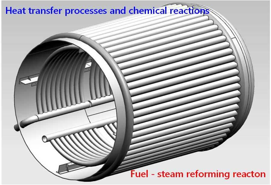
28,
29]. In the CRGTs, chemical endothermic reactions such as fuel-steam reforming reactions are used to transform the exhaust gas enthalpy into the chemical energy of synthetic hydrogen-rich fuels, and new fuels are fed into the gas turbine combustors. Thus, waste heat can be recuperated to improve the overall thermal efficiency of the power system. After chemical reactions, original fuels are changed to new synthetic hydrogen-rich fuels that have better combustion characteristics because of hydrogen’s high flame speed and very short ignition delay time [
30,
31,
32].
A chemical reformer is a device in which the chemical endothermic reactions occur. The heat transfer process also takes place in this device. Both for the design and performance calculation of the chemical reformer, a precise and proper simplified model is needed. Necessarily, this model should include mathematic presentations of the chemical reaction and heat transfer process. Nowadays, there are two ways to model the chemical reformer. The first one is the numerical method, which adopts the computational fluid dynamics with consideration of energy equation, species equation, and chemical reaction [
33,
34]. This method has high accuracy but also requires considerable resources, which is suitable for some special working conditions but not appropriate for performance calculation under full working conditions. The other method adopts lumped parameter method modeling heat transfer processes and chemical reactions [
35]. This is a convenient way to calculate performance, but recognizes fewer structural parameters.
To model the chemical regenerators, the focus should be placed on calculating the heat absorbed by chemical endothermic reactions and the compositions out of chemical reformers. So far, various chemical endothermic reactions have been used for thermochemical waste heat recuperation [
36,
37,
38,
39,
40]. Steam reforming experiments of methane [
34], methanol, and dimethyl ether [
41] have been carried out to obtain characteristics data under some working conditions. Based on the limited fuel-steam reforming data or immature reaction mechanisms, computational fluid dynamics (CFD) methods are used to investigate the structural design of the chemical reformers [
33,
37,
42]. Obviously, such a method is not easily adapted to obtain characteristic data under all working conditions and to design chemical reformers. By the criterion that the Gibbs free energy of the system reaches minimization, the minimization of Gibbs free energy (MGFE) method can calculate the products under each given working condition easily [
28,
43,
44]. With the addition of a method to decouple chemical reactions and the heat transfer process, thermodynamic designs of the chemical reformers can be performed step by step.
There are two important issues that should be solved in thermodynamic design and performance calculation of chemical reformers: (1) mathematical description of fuel-steam reforming; (2) thermodynamic design and simulation of chemical reformers. To solve these problems, the this paper proposes the following: (1) to inspect the coupling design process of heat transfer and chemical reaction; (2) to establish an accurate and reliable performance calculation model for chemical reformers and to verify model availability; (3) to study the influence of structure complexity on the chemical reformers characteristics.
2. Configuration of Chemical Reformers
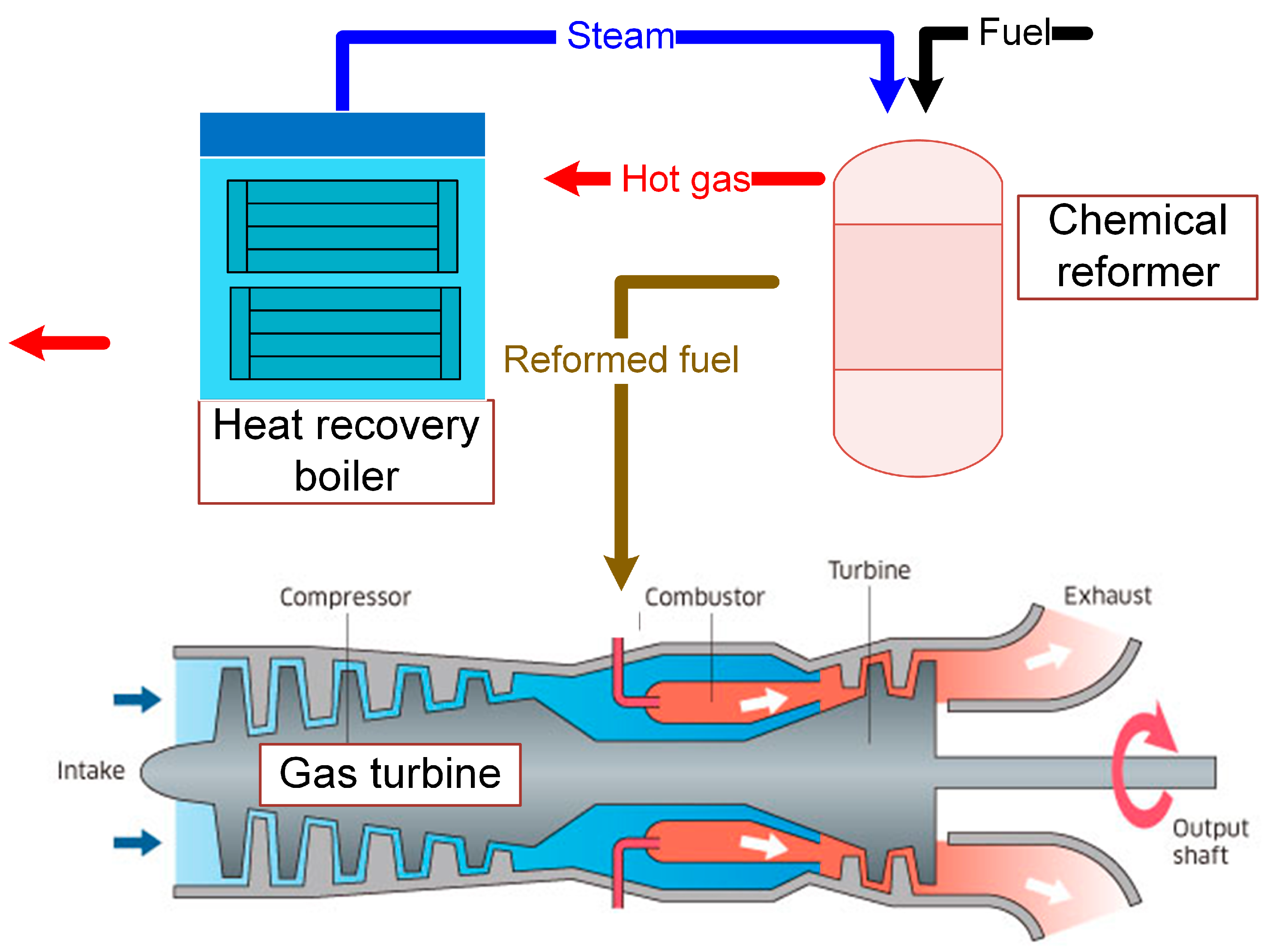
Figure 1 shows a simple CRGT configuration based on a gas turbine with one spool shaft and one free power turbine. The reformed fuel combusts with the compressed air from the compressor to produce hot gas. The hot gas powers the turbines and then runs to the chemical reformer and the heat recovery boiler in sequence. The fuel-steam reforming reaction takes place in the chemical reformer and the heat recovery boiler produces high-pressure steam for the chemical reaction.
In most cases, the heat of the exhaust gas out of the gas turbine is about 800 K. Fuel-steam reforming reactions are chosen as the chemical endothermic reactions, in general. Due to its accessibility and portability, methane is selected as the fuel in the concept research. Besides, among the typical hydrocarbons, methane has a high conversion efficiency in fuel-diesel reforming reactions. It has been verified that the products of the methane-steam reforming consist of CH
4, H
2O, H
2, C, CO and CO
2 [
42]. The overall energy fed into the gas turbine includes the energy carried by the fuel and that recovered from the exhaust gas. Based on this, the overall energy can be represented by all the energy carried by the reformed fuel that can be calculated as the enthalpies and heating values of all the products. The energy can be described as the corrected heating value of the reformed fuel, which is written in Equation 1. Then, the overall energy into the combustor is calculated by the product of the corrected heating value and the mass of the reformed fuel.
where,
is the corrected heating value of the fuel, kJ/kg,
, , , are the mole numbers of the CH4, CO, H2 and fuel, respectively, mol,
, , are the molar masses of the CH4, CO, H2 and fuel, respectively, kg/mol,
, , are the low heating values of the CH4, CO and H2, respectively, kJ/kg,
is the mass of the reformed fuel, kg,
is the enthalpy of the reformed fuel, kJ/kg.
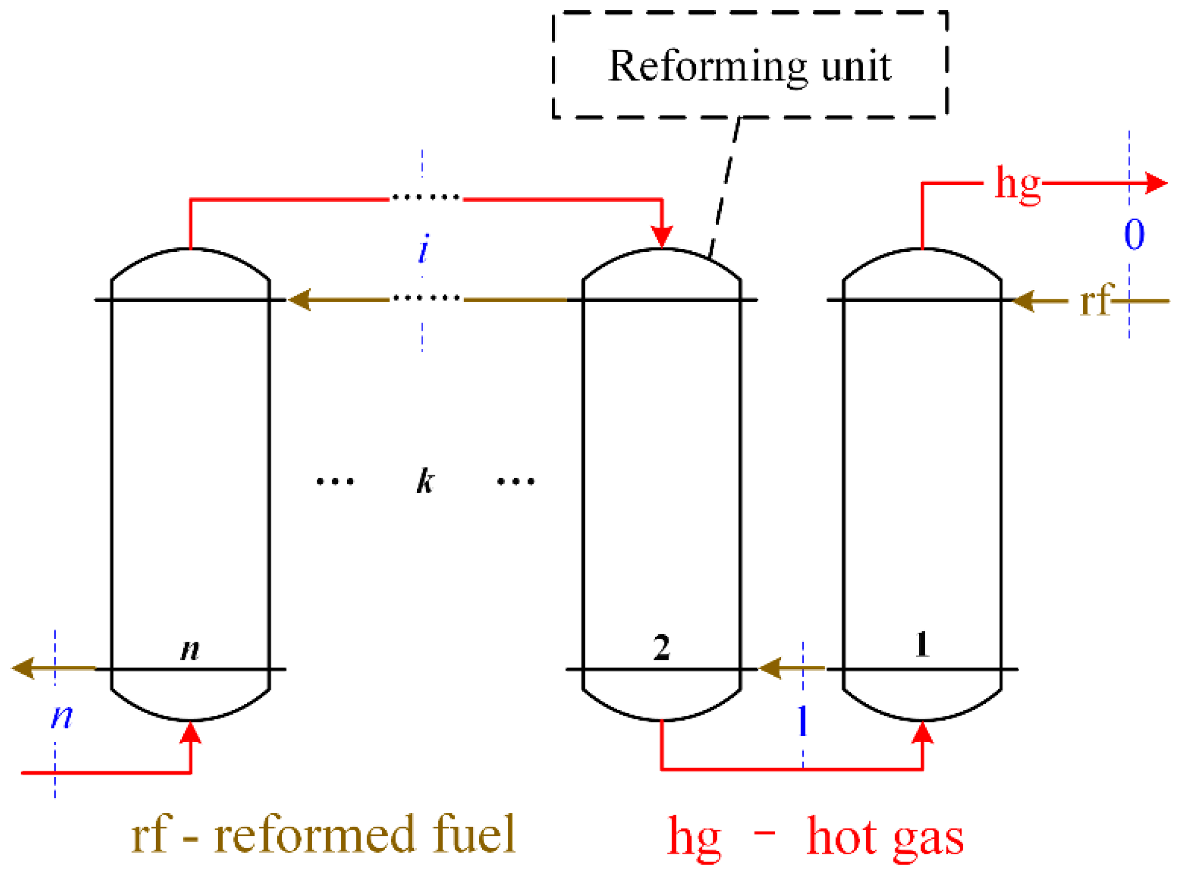
A chemical reformer is the core device in which the endothermic reactions take place to recover the waste heat and to reform the fuel. The chemical reformer consists of some heat exchangers and cracking reactors. Here, one heat exchanger and one cracking reactor are described as one reforming unit and the chemical reformer may consist of several reforming units. The fuel and steam mixture firstly enters the heat exchanger and its temperature rises. The high-temperature reactants then react adiabatically in the cracking reactor.
Figure 2 shows the arrangement of the chemical reformer and its fluid streams of each working fluid.
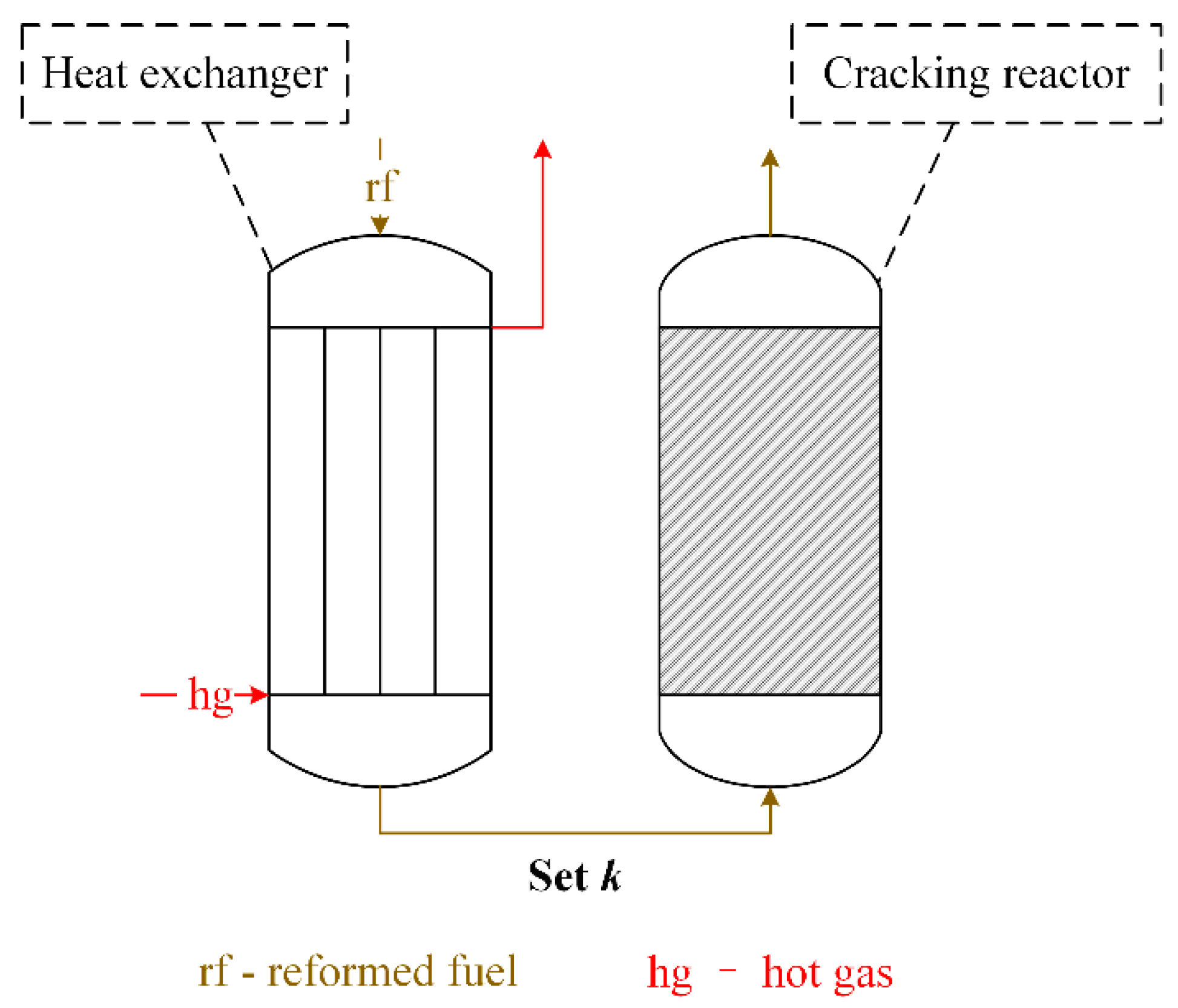
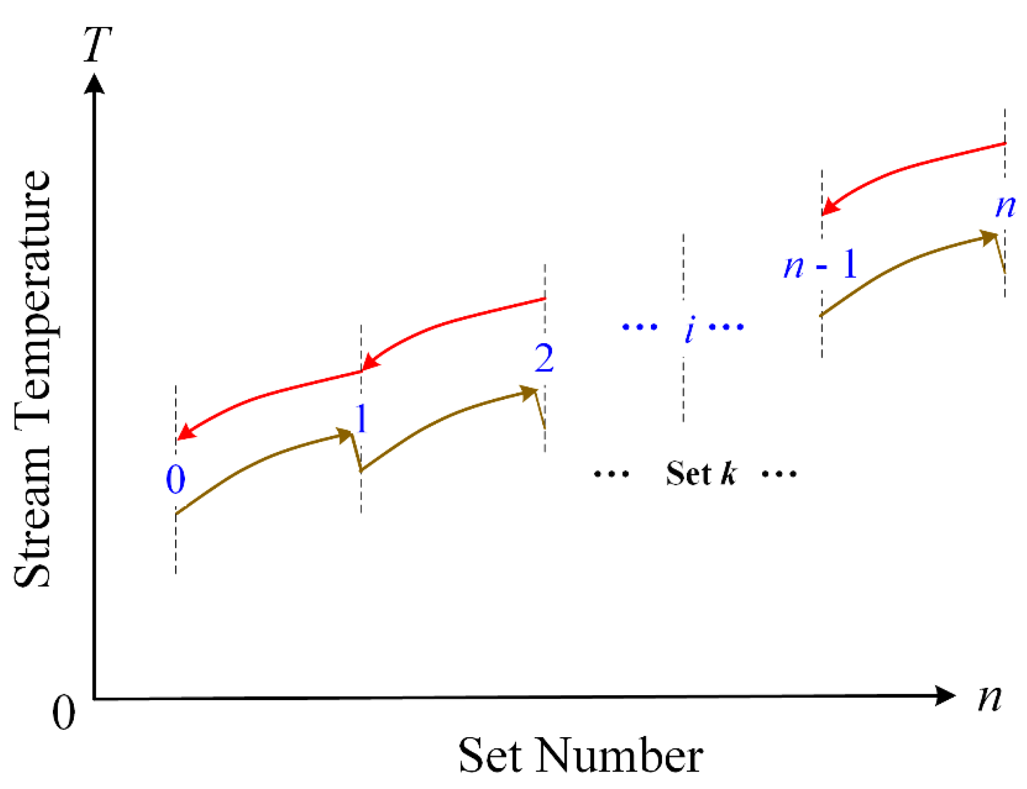
Figure 3 shows the structure of each reforming unit. The temperatures along the fluid streams are depicted in
Figure 4. It is shown that the temperature of the reformed fuel ascends in the heat exchangers and descends in the cracking reactors.
3. Modeling the Chemical Reformer
Based on the configuration of the chemical reformer, shown in
Figure 2, the modeling of this device includes two parts: (1) modeling one reforming unit; (2) designing the algorithm for the simulation of series-wound reforming units. The first part is to model the heat transfer process in heat exchangers and the adiabatic fuel-steam reforming reaction in cracking reactors.
3.1. Models of One Reforming Unit
As shown in
Figure 2, fuel-steam reforming reactions take place in each cracking reactor. In each cracking reactor, the reactants are the products from the previous cracking reactor. That is to say, the reactants fed into different cracking reactors are not the same. A universal model for each different fuel-steam reforming reaction needs to be established. Each heat exchanger should be thermodynamically designed and its simulation models are also indispensable.
3.1.1. Fuel-Steam Reforming Reactions Modeled by Minimization of Gibbs Free Energy (MGFE) Method
The products of the C
xH
yO
z-steam reforming reaction will be C, CO, CO
2, H
2, CH
4 and H
2O [
36]. The fuel-steam reforming is basically the following reaction:
However, this basic reaction can be only used in the first cracking reactor calculation because of the more complicated reactants in the other cracking reactors. A universal model should be used to represent this kind of reactions in the following form:
where,
stands for the chemical symbol of species ,
is the stoichiometric coefficients of the reactant ,
is the stoichiometric coefficients of the product .
The minimization of Gibbs free energy (MGFE) method is appropriate for developing this form of reforming reactions. By the criterion that the Gibbs free energy of the system reaches minimization [
43,
44,
45,
46], the MGFE method can calculate the products under each given working condition easily, without consideration of catalysts and reformer structures.
The Gibbs energy of the system can be calculated as Equation (4),
For real gas,
ui is calculated as Equation (5), in which
f is fugacity,
Thus, Equation (5) transforms into Equation (6),
The balancing process of the reforming reaction converts to a nonlinear optimization to acquire the minimization of Equation (6). Element balance-constrained conditions are a limitation of the optimization. Set the input conditions to be 1 mol and a mol . The element balance-constrained conditions can be presented as the following:
Element balance constrained conditions for C, H and O are presented in Equations (7)–(9), respectively,
And the stoichiometric coefficients are non-negative,
In an adiabatic reforming reaction, the following heat equilibrium must be satisfied,
3.1.2. The Epsilon-NTU (Number of Transfer Units) Method to Model the Heat Exchangers
The epsilon-NTU method is used to calculate the rate of heat transfer in counter-current heat exchangers. Two concepts, the heat exchanger effectiveness and the number of transfer units (NTU), are introduced and the heat transfer rate can be calculated based on them.
The heat exchanger effectiveness
as the Equation (12),
where,
is the maximum possible heat transfer rate for the exchanger while
is the actual heat transfer rate.
where
and
are the specific heat capacity rate ratios for the hot fluid and cold fluid, respectively.
The heat exchanger effectiveness
can also be expressed as the Equation (16).
For counter-current flows,
By the epsilon-NTU method, the simulation of heat exchangers can be performed given the input temperatures of hot and cold fluids.
3.2. Algorithms for Simulation of Series-Wound Reforming Units
For the reforming unit shown in
Figure 3, the outlet temperatures can be calculated based on the models presented in
Section 3.1, directly. The mass flow rates of both the hot and cold fluids remain unchanged from the entrance to the exit. The outlet pressures for both fluids can be calculated as the following equation:
where,
and are the inlet and outlet pressures,
and are the mass flow rate and pressure drop under design working condition, respectively,
is the mass flow rate under a given working condition.
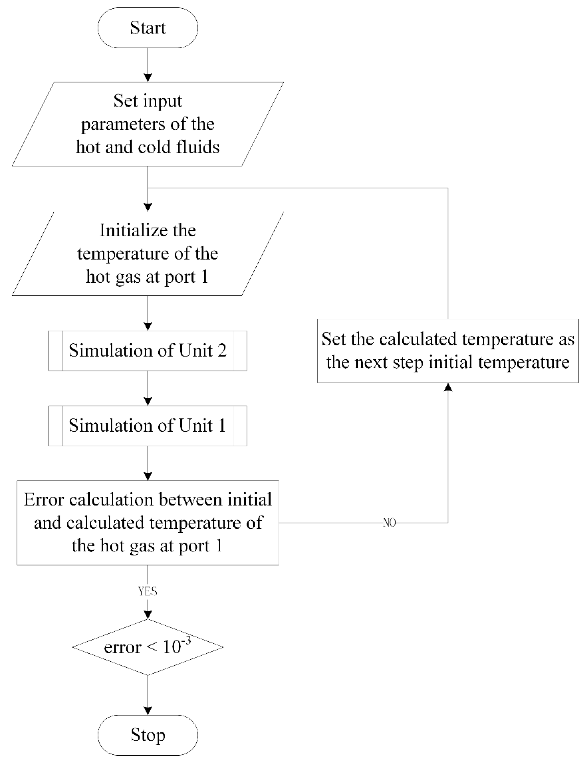
However, for series-wound reforming units, the inlet parameters of all the reforming units are not given. Conversely, the inlet parameters of some reforming units are parameters to be solved. An iterative solution is necessary for this problem.
Figure 5 shows the solution process of two reforming units. The solution process of more reforming units is similar, except that the nesting level is increased. The sub-process to simulate one reforming unit is shown in
Figure 6.
4. Results and Discussion
The chemical reformer performance calculation program is programmed in MATLAB (2016b, The MathWorks, Inc, Natick, MA, USA). The sequential quadratic programming algorithm is used to find a local minimum that satisfies the constraints in the MGFE method. Here, the MGFE method is verified by comparative analysis between the calculations of the CH4-steam reforming reactions and experimental results under different working conditions. Simulations of different numbers of reforming units are also performed to determine an optimal structure design criterion of the chemical reformer.
4.1. The CH4-Steam Reforming Reactions
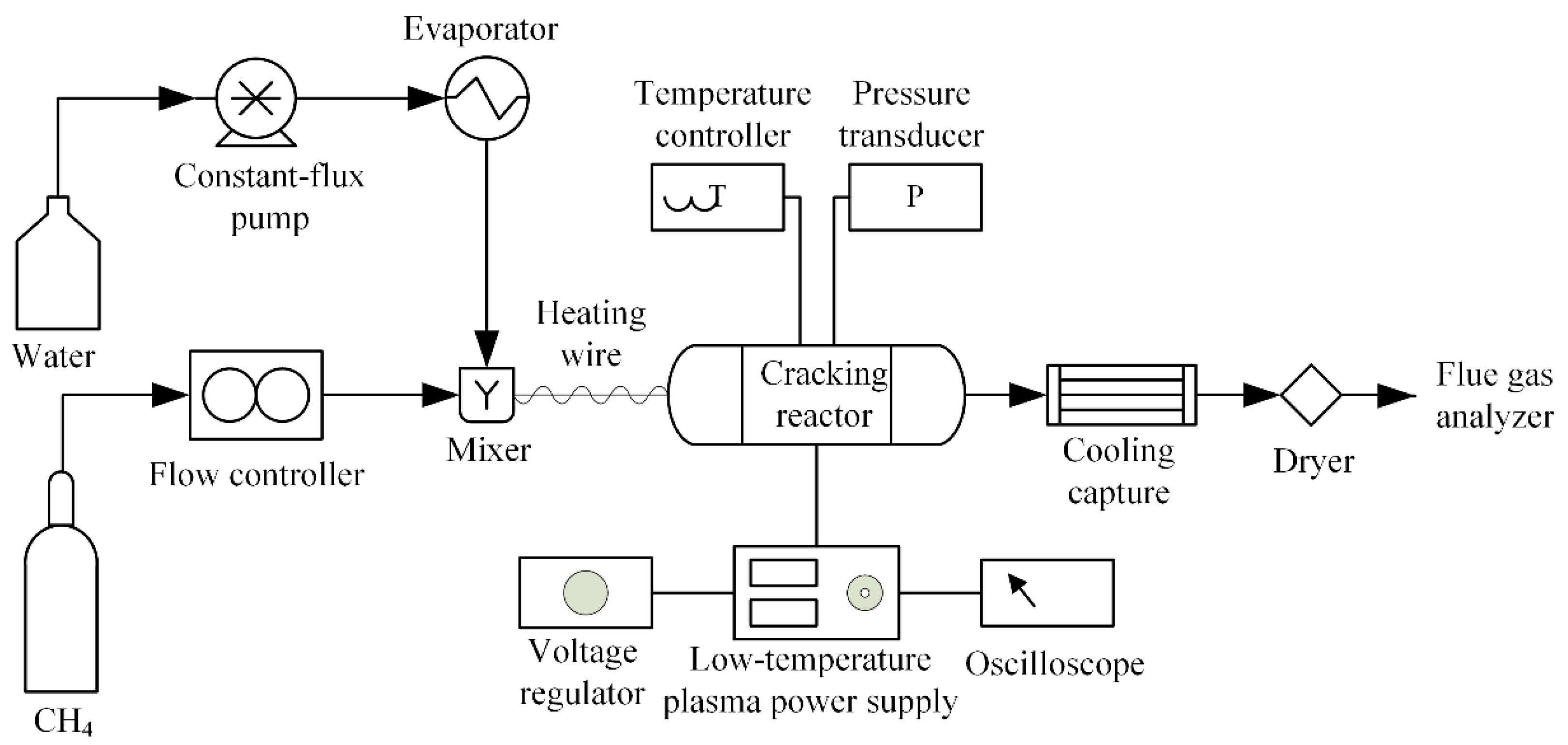
A plasma catalyzed CH
4-steam reforming reaction experiment is performed, and its arrangement diagram is shown as the following
Figure 7. The mixture of CH
4 and steam is fed into the cracking reactor which can keep a constant temperature. A low-temperature plasma catalyst is also used in this reaction. A flue gas analyzer is used to detect the composites and the mole fraction of each composite in the products. More details of these experiments can be found in our previous work [
42].
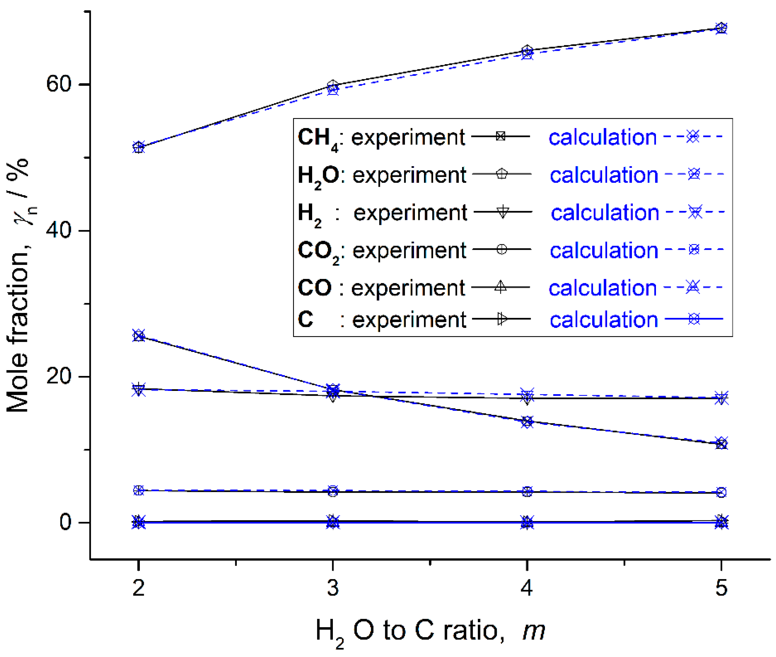
In this experiment, the composites of the products are CH
4, H
2O, H
2, CO
2, CO and C. Under the working conditions that the pressure is 1atm, the temperature is 400 °C and the water to carbon ration varies from 2 to 5, all the composites and their mole productions corresponding to 1 mol CH
4 supply are listed in
Table 1. The results calculated by the MGFE method are listed in
Table 2. Based on these data, the mole fractions of all the composite are depicted in
Figure 8.
C is one of the products in the experiment, and its mole fraction is very low. However, whether C is set as the product or not, there is no C in the calculation results, when the CH4-steam reforming reaction is calculated by the MGFE method. This may be caused by some accessional reactions in the experiment. The experiment can be improved by further optimization. The mole fraction of CO is very low in the calculation and zero in the experiment, under some working conditions. Thus, C and CO are not important objects.
Errors between experiments and calculations for main products in the CH
4-steam reforming reaction are presented in
Table 3. The main products include CH
4, H
2O, H
2 and CO
2. The highest error for all the main products under all working conditions is 4.86%. That is an acceptable error in the engineering calculation.
Based on these analyses, it can be said that the MGFE method is appropriate for the calculation of the CH4-steam reforming reaction. In the design and performance calculation of the chemical reformer, the MGFE method will be used as a universal tool to model the CH4-steam reforming reaction.
4.2. Performance of Different Numbers of Reforming Units
The basic arrangement of the chemical reformer is shown in
Figure 2. The thermodynamic design of the chemical reformer defines the numbers of reforming units and the thermodynamic parameters of each heat exchanger. There is a basic requirement for the chemical reformer that the number of reforming units is limited to prevent the system from being too complicated and to ensure the reliability of the system operation. Here, up to three sets of reforming units are thermodynamically designed and their performances are comparatively analyzed to derive a design principle for the chemical reformer.
The main performance parameters of the prototype gas turbine engine can be found in our previous work [
27,
28]. The thermodynamic design of heat exchangers can be performed referring to the literature [
47]. Considering the reaction progress and water consumption, a satisfactory value of H
2O to C ratio is 4 and previous research confirms this [
18,
19,
20,
21,
22,
23,
24,
25,
27,
28,
43]. The design conditions of the chemical reformer are listed in
Table 4.
Thermodynamic designs of the heat exchangers are performed by the Aspen Exchanger Design and Rating. The simulations of the three types of chemical reformer are performed by MATLAB code programming based on the models in
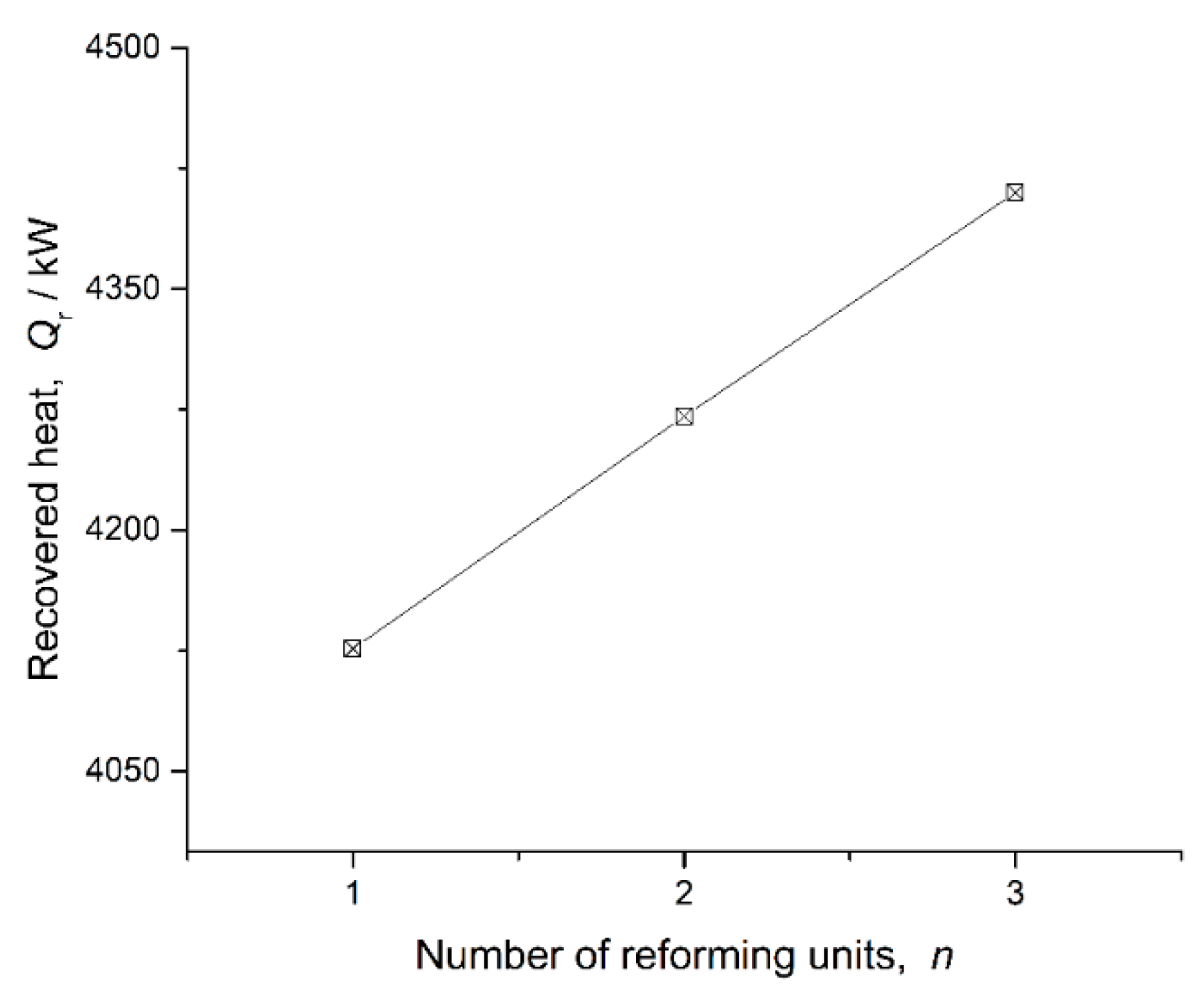
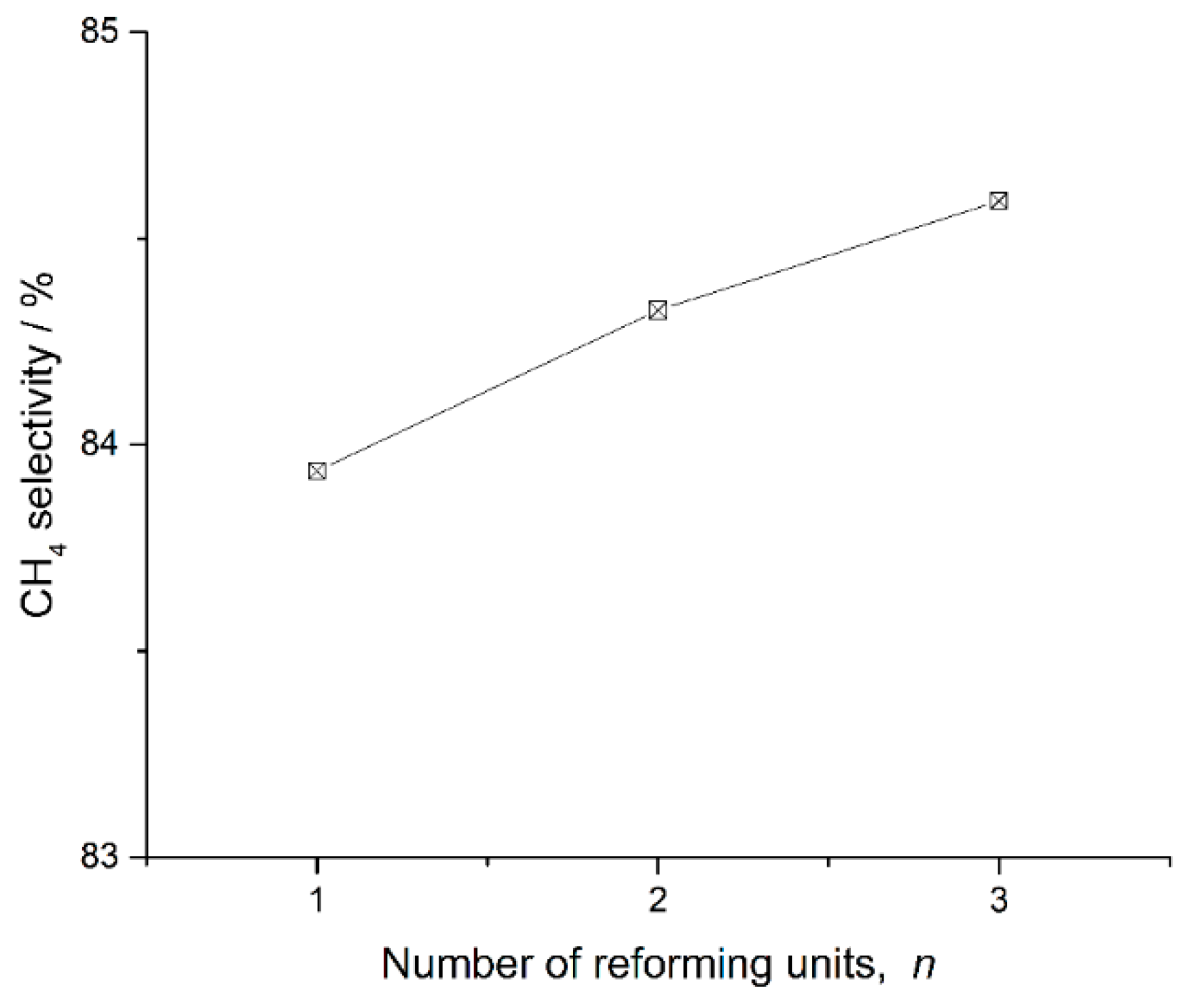
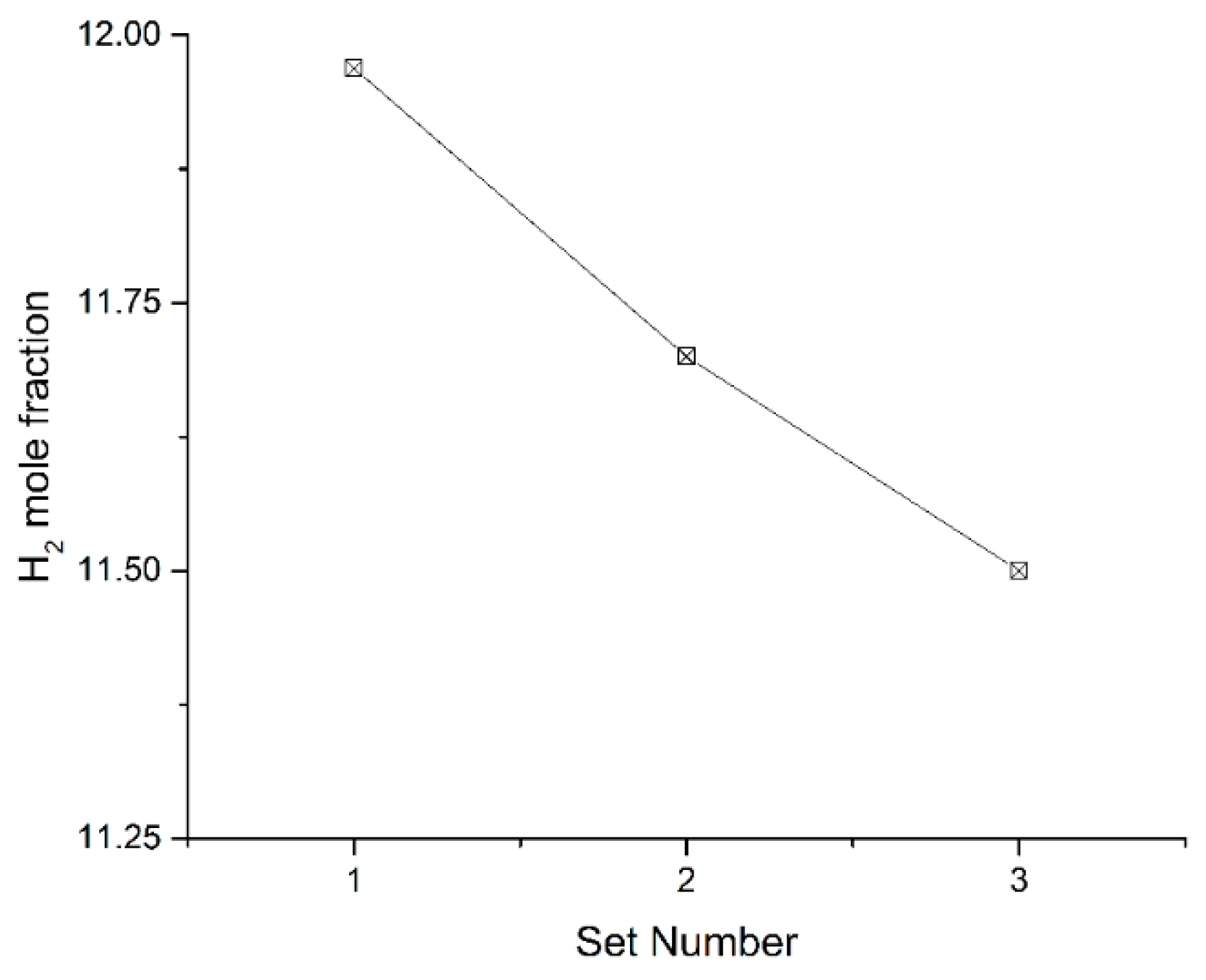
Section 3. Chemical reformers with one, two and three sets of reforming units are studied. Their main performance parameters are presented in
Figure 9,
Figure 10 and
Figure 11. The selectivity of CH
4 in products can represent the reforming reaction progress. Lower values of the selectivity of CH
4 represent greater reforming reaction progress. This value can be described as Equation (19).
The recovered heat of the chemical reformer and the value of the selectivity of CH4 increase, while the H2 mole fraction in products decreases, as the number of reforming units increases. That is to say, chemical reformers with a large number of reforming units can recuperate more waste heat, and chemical reformers with a small number of reforming units can provide hydrogen richer fuel for better combustion quality. For different application scenarios, appropriate solutions for chemical reformers can be determined following this principle.
5. Conclusions
Chemical reformers are used in power machines to improve the overall efficiency and combustion characteristics. To derive an appropriate design principle for chemical reformers, models of chemical reformers are built based on the structure analysis and a performance calculation program is built. The conclusions are as follows:
(1) A basic structure of a chemical reformer, consisting of heat exchangers and cracking reactors, is built. One heat exchanger and one cracking reactor construct make up a reforming unit, and the numbers of the reforming units can be determined after thermodynamic design and performance analysis.
(2) Models of the reforming units are built. A universal model of the fuel-steam reforming reaction is built based on the minimization of Gibbs free energy (MGFE) method. Compared with the results of plasma-catalyzed CH4-steam reforming reaction experiments, the calculation has high precision and can be used to guide the improvement of the experimental scheme.
(3) The performance calculation program of the chemical reformer is coded. After the thermodynamic design of the chemical reformers with three different numbers of reforming units, their performances are calculated and comparatively analyzed. The chemical reformer with a large number of reforming units can recuperate more waste heat, and the chemical reformer with a small number of reforming units can provide hydrogen richer fuel for better combustion quality. For different application scenarios, appropriate solutions for chemical reformers can be determined following this principle.
Author Contributions
Conceptualization, F.P. and X.C.; methodology, F.P.; software, F.P.; validation, F.P. and X.C.; investigation, X.W. (Xin Wu); data curation, F.P., X.W. (Xin Wu) and X.W. (Xin Wang); writing—review and editing, F.P., J.G. and X.C.; visualization, F.P., X.W. (Xin Wu) and X.W. (Xin Wang); funding acquisition, F.P.
Funding
This work was supported by the financial support of China Postdoctoral Science Foundation funded the project (No. 2017M622436).
Conflicts of Interest
The authors declare no conflict of interest.
References
- Bonforte, G.; Buchgeister, J.; Manfrida, G.; Petela, K. Exergoeconomic and exergoenvironmental analysis of an integrated solar gas turbine/combined cycle power plant. Energy 2018, 156, 352–359. [Google Scholar] [CrossRef]
- Liu, Z.; Karimi, I.A. New operating strategy for a combined cycle gas turbine power plant. Energy Convers. Manag. 2018, 171, 1675–1684. [Google Scholar] [CrossRef]
- Van Erdeweghe, S.; Van Bael, J.; Laenen, B.; D’haeseleer, W. Design and off-design optimization procedure for low-temperature geothermal organic Rankine cycles. Appl. Energy 2019, 242, 716–731. [Google Scholar] [CrossRef]
- Hoang, A.T. Waste heat recovery from diesel engines based on Organic Rankine Cycle. Appl. Energy 2018, 231, 138–166. [Google Scholar] [CrossRef]
- Imran, M.; Haglind, F.; Asim, M.; Zeb Alvi, J. Recent research trends in organic Rankine cycle technology: A bibliometric approach. Renew. Sustain. Energy Rev. 2018, 81, 552–562. [Google Scholar] [CrossRef]
- Sanaye, S.; Amani, M.; Amani, P. 4E modeling and multi-criteria optimization of CCHPW gas turbine plant with inlet air cooling and steam injection. Sustain. Energy Technol. Assess. 2018, 29, 70–81. [Google Scholar] [CrossRef]
- Guteša Božo, M. Fuel rich ammonia-hydrogen injection for humidified gas turbines. Appl. Energy 2019, 251, 113334. [Google Scholar] [CrossRef]
- Choudhary, T.; Sahu, M.K. Energy and Exergy Analysis of Solid Oxide Fuel Cell Integrated with Gas Turbine Cycle—“A Hybrid Cycle”. In Renewable Energy and Its Innovative Technologies; Chattopadhyay, J., Singh, R., Prakash, O., Eds.; Springer: Singapore, 2019; pp. 139–153. [Google Scholar]
- Oryshchyn, D.; Harun, N.F.; Tucker, D.; Bryden, K.M.; Shadle, L. Fuel utilization effects on system efficiency in solid oxide fuel cell gas turbine hybrid systems. Appl. Energy 2018, 228, 1953–1965. [Google Scholar] [CrossRef]
- Azizi, M.A.; Brouwer, J. Progress in solid oxide fuel cell-gas turbine hybrid power systems: System design and analysis, transient operation, controls and optimization. Appl. Energy 2018, 215, 237–289. [Google Scholar] [CrossRef]
- Cengel, Y.A.; Cimbala, J.M.; Turner, R.H.; Kanoglu, M. Fundamentals of Thermal-Fluid Sciences, 5th ed.; McGraw-Hill Education: New York, NY, USA, 2016. [Google Scholar]
- Alfellag, M.A.A. Parametric investigation of a modified gas turbine power plant. Therm. Sci. Eng. Prog. 2017, 3, 141–149. [Google Scholar] [CrossRef]
- Weiliang, W.; Shusheng, Z.; Ce, Z. Study of the Hydrogen-Steam Turbine Composite Cycle. Procedia CIRP 2015, 26, 735–739. [Google Scholar] [CrossRef]
- Aly, S.E. Gas turbine waste heat recovery distillation system. Heat Recovery Syst. CHP 1987, 7, 375–382. [Google Scholar] [CrossRef]
- Buyadgie, D.; Buyadgie, O.; Drakhnia, O.; Brodetsky, P.; Maisotsenko, V. Solar low-pressure turbo-ejector Maisotsenko cycle-based power system for electricity, heating, cooling and distillation. Int. J. Low-Carbon Technol. 2015, 10, 157–164. [Google Scholar] [CrossRef]
- Olmsted, J.H.; Grimes, P.G. Heat engine efficiency enhancement-through chemical recovery of waste heat. In Proceedings of the 7th Intersociety Energy Conversion Engineering Conference, San Diego, CA, USA, 25 September 1972; pp. 241–248. [Google Scholar]
- Janes, J. Chemically Recuperated Gas Turbine; P500-92-015; California Energy Commission: Sacramento, CA, USA, 1992.
- Harvey, S.; Kane, N.D. Analysis of a reheat gas turbine cycle with chemical recuperation using Aspen. Energy Convers. Manag. 1997, 38, 1671–1679. [Google Scholar] [CrossRef]
- Carcasci, C.; Facchini, B.; Harvey, S. Modular approach to analysis of chemically recuperated gas turbine cycles. Energy Convers. Manag. 1998, 39, 1693–1703. [Google Scholar] [CrossRef][Green Version]
- Abdallah, H.; Harvey, S. Thermodynamic analysis of chemically recuperated gas turbines. Int. J. Therm. Sci. 2001, 40, 372–384. [Google Scholar] [CrossRef]
- Carapellucci, R.; Milazzo, A. Thermodynamic optimization of a reheat chemically recuperated gas turbine. Energy Convers. Manag. 2005, 46, 2936–2953. [Google Scholar] [CrossRef]
- Hongtao, Z.; Yulong, Z.; Ren, Y. Simulation research of the CRGT cycle gas turbine performance. J. Aerosp. Power 2012, 27, 118–123. [Google Scholar]
- Luo, C.; Zhang, N. Zero CO2 emission SOLRGT power system. Energy 2012, 45, 312–323. [Google Scholar] [CrossRef]
- Zhang, N.; Lior, N. Use of Low/Mid-Temperature Solar Heat for Thermochemical Upgrading of Energy, Part I: Application to a Novel Chemically-Recuperated Gas-Turbine Power Generation (SOLRGT) System. J. Eng. Gas Turbines Power 2012, 134, 072301. [Google Scholar] [CrossRef]
- Ni, M.; Yang, T.; Xiao, G.; Ni, D.; Zhou, X.; Liu, H.; Sultan, U.; Chen, J.; Luo, Z.; Cen, K. Thermodynamic analysis of a gas turbine cycle combined with fuel reforming for solar thermal power generation. Energy 2017, 137, 20–30. [Google Scholar] [CrossRef]
- Pashchenko, D. Energy optimization analysis of a thermochemical exhaust gas recuperation system of a gas turbine unit. Energy Convers. Manag. 2018, 171, 917–924. [Google Scholar] [CrossRef]
- Fumin, P.; Hongtao, Z.; Qingzhen, L.; Ren, Y. Design and performance calculations of chemically recuperated gas turbine on ship. Proc. Inst. Mech. Eng. Part A 2013, 227, 908–918. [Google Scholar]
- Fumin, P.; Hongtao, Z.; Pingping, L.; Ren, Y. Configuration Discussions of the Chemically Recuperated Gas Turbine Powering a Ship. In Proceedings of the International Conference on Advances in Mechanical Engineering and Industrial Informatics, Zhengzhou, China, 11–12 April 2015. [Google Scholar]
- Carapellucci, R.; Giordano, L. Upgrading existing gas-steam combined cycle power plants through steam injection and methane steam reforming. Energy 2019, 173, 229–243. [Google Scholar] [CrossRef]
- Cappelletti, A.; Martelli, F. Investigation of a pure hydrogen fueled gas turbine burner. Int. J. Hydrog. Energy 2017, 42, 10513–10523. [Google Scholar] [CrossRef]
- Schönborn, A.; Sayad, P.; Konnov, A.A.; Klingmann, J. OH*-chemiluminescence during autoignition of hydrogen with air in a pressurised turbulent flow reactor. Int. J. Hydrog. Energy 2014, 39, 12166–12181. [Google Scholar] [CrossRef]
- Valera-Medina, A.; Pugh, D.G.; Marsh, P.; Bulat, G.; Bowen, P. Preliminary study on lean premixed combustion of ammonia-hydrogen for swirling gas turbine combustors. Int. J. Hydrog. Energy 2017, 42, 24495–24503. [Google Scholar] [CrossRef]
- Lee, J.; Han, J.H.; Moon, J.H.; Jeong, C.H.; Kim, M.; Kim, J.Y.; Lee, S.H. Characteristics of heat transfer and chemical reaction of methane-steam reforming in a porous catalytic medium. J. Mech. Sci. Technol. 2016, 30, 473–481. [Google Scholar] [CrossRef]
- Chen, J.; Liu, B.; Gao, X.; Xu, D. Production of Hydrogen by Methane Steam Reforming Coupled with Catalytic Combustion in Integrated Microchannel Reactors. Energies 2018, 11, 2045. [Google Scholar] [CrossRef]
- Kyriakides, A.-S.; Voutetakis, S.; Papadopoulou, S.; Seferlis, P. Integrated Design and Control of Various Hydrogen Production Flowsheet Configurations via Membrane Based Methane Steam Reforming. Membranes 2019, 9, 14. [Google Scholar] [CrossRef]
- Popov, S.K.; Svistunov, I.N.; Garyaev, A.B.; Serikov, E.A.; Temyrkanova, E.K. The use of thermochemical recuperation in an industrial plant. Energy 2017, 127, 44–51. [Google Scholar] [CrossRef]
- Pashchenko, D. Effect of the geometric dimensionality of computational domain on the results of CFD-modeling of steam methane reforming. Int. J. Hydrog. Energy 2018, 43, 8662–8673. [Google Scholar] [CrossRef]
- Liu, L.; Kumar, S.; Wang, Z.; He, Y.; Liu, J.; Cen, K. Catalytic effect of metal chlorides on coal pyrolysis and gasification part I. Combined TG-FTIR study for coal pyrolysis. Thermochim. Acta 2017, 655, 331–336. [Google Scholar] [CrossRef]
- Pashchenko, D.I. Thermochemical recovery of heat contained in flue gases by means of bioethanol conversion. Therm. Eng. 2013, 60, 438–443. [Google Scholar] [CrossRef]
- Pashchenko, D. Thermodynamic equilibrium analysis of combined dry and steam reforming of propane for thermochemical waste-heat recuperation. Int. J. Hydrog. Energy 2017, 42, 14926–14935. [Google Scholar] [CrossRef]
- Nakagaki, T.; Watanabe, T. OS4-2 Design of DME Steam Reformer for Chemically Recuperated Gas Turbine System. Proc. Natl. Symp. Power Energy Syst. 2006, 2006.11, 115–118. [Google Scholar] [CrossRef]
- Liu, Q.; Zheng, H.; Cai, L.; Long, Q.; Yang, R. CFD Modeling of Exhaust Heat Recovery Using Methane Steam Reforming in Steam Reformer of Chemically Recuperated Gas Turbine. J. Conv. Inf. Technol. 2012, 23, 10. [Google Scholar]
- Mathieu, P.; Dubuisson, R. Performance analysis of a biomass gasifier. Energy Convers. Manag. 2002, 43, 1291–1299. [Google Scholar] [CrossRef]
- Nikoo, M.B.; Mahinpey, N. Simulation of biomass gasification in fluidized bed reactor using ASPEN PLUS. Biomass Bioenergy 2008, 32, 1245–1254. [Google Scholar] [CrossRef]
- Tang, H.; Kitagawa, K. Supercritical water gasification of biomass: Thermodynamic analysis with direct Gibbs free energy minimization. Chem. Eng. J. 2005, 106, 261–267. [Google Scholar] [CrossRef]
- Shen, L.; Gao, Y.; Xiao, J. Simulation of hydrogen production from biomass gasification in interconnected fluidized beds. Biomass Bioenergy 2008, 32, 120–127. [Google Scholar] [CrossRef]
- Kuppan, T. Heat Exchanger Design Handbook, 2nd revised ed.; Marcel Dekker Inc.: New York, NY, USA, 2013. [Google Scholar]
© 2019 by the authors. Licensee MDPI, Basel, Switzerland. This article is an open access article distributed under the terms and conditions of the Creative Commons Attribution (CC BY) license (http://creativecommons.org/licenses/by/4.0/).


