1. Introduction
Heading driving is one of the core underground mining operations performed to uncover deposits and prepare them for exploitation. The costs incurred to uncover deposits and perform preparatory works have a significant effect on the economic efficiency of mining, especially in the case of deep deposits and more challenging geological conditions. In order for the mining to be more concentrated, it is necessary to develop a technology that facilitates driving preparatory workings at advance rates high enough to reduce mining costs. High advance rates can be achieved only when the driving process is mechanized as much as possible. This involves comprehensive mechanization, in which the selection of all the machines and tools used on the mining site is based not only on the mining and geological conditions, but also on the relationship between their technical and mining parameters. Only such a selection can provide both high driving efficiency and substantial economic efficiency.
The main step in a mechanization project is to identify the heading driving process in specific conditions, while machine selection requires primarily the identification of the operation a machine will perform in such conditions, factoring in additional conditions related to cooperation with other elements of the system.
Tunnel and roadway driving is a very complex process due to considerable difficulties and limitations of geological and mining, as well as technical nature. These works are considered among the most labor-intensive and time-consuming. The basic factors underlying the choice of the heading driving technique are [
1,
2]:
the natural conditions in which the heading is driven;
the heading’s functionality in terms of how it will be used in the future;
the heading’s length and cross-section, and the methods employed to protect it against rockfalls and convergence due to rock mass pressure;
the time in which the working should be completed.
The separation of rock from the solid, i.e., the mining process, is the first operation in a sequence of technological processes involved in heading driving or useful-mineral mining. As such, it is a core mining operation. This process is used not only in mining. Such operations are also common in construction works involving excavations, tunnels, and digging foundations, etc.
A definition of mining as a process in which rock pieces are separated from the solid does not fully reflect the nature of the process, and may lead one to consider mining as being equivalent to the physical process of rock breakage, which is essentially an energetic process. In addition to energy transformation, mining must involve information processing to control the disintegration of the primary rock structure such that the objective can be achieved. In addition, the objective is to extract rock in a specific geometric range (a specific grade), or to drive a heading with a specific geometric shape and specific cross-sectional parameters. Hence, mining represents a significant factor in the costs of driving development and preparatory workings, and in the broadly defined mining costs.
The time needed to complete preparatory workings is directly associated with the time required to open up the longwall for exploitation, or with the longwall advance when its gate is driven in advance. When the deposit is cut in advance, the driving rate must correlate with the plans for longwall opening. With tunneling, it is different. In this process, the faster technologies are not always cost-effective, even when earlier project completion is desirable. However, financial analyses warrant the assumption for a given technology that the greater the driving rate, the lower the unit cost of driving one linear meter of a working [
1].
2. Compact-Rock Mining Methods
The mining methods that have gained common acceptance in some applications, and are used on a wider basis, can be described as conventional methods. These include rock mining by blasting, also known as traditional rock mining, and the most common methods of mechanical rock mining, such as:
cutting;
milling, including cutting;
driving based on cutting consistency (rotary drilling);
driving based on hammering consistency (percussion drilling);
combine driving based on cutting and hammering consistency (percussion and rotary drilling);
driving based on static-load consistency (roller drilling).
Other mechanical mining methods are considered as non-conventional. These include methods involving:
rock mining based on static crumpling and reeling using symmetrical and asymmetrical disk tools;
undercutting with asymmetrical disc tools with the static direction of pressure force.
non-conventional methods also include non-mechanical methods such as:
rock mining with high-pressure water jetting;
rock mining with a high-energy gas stream from cutting torches;
rock mining with high-frequency currents;
electrohydrodynamic rock mining;
rock mining with swelling materials.
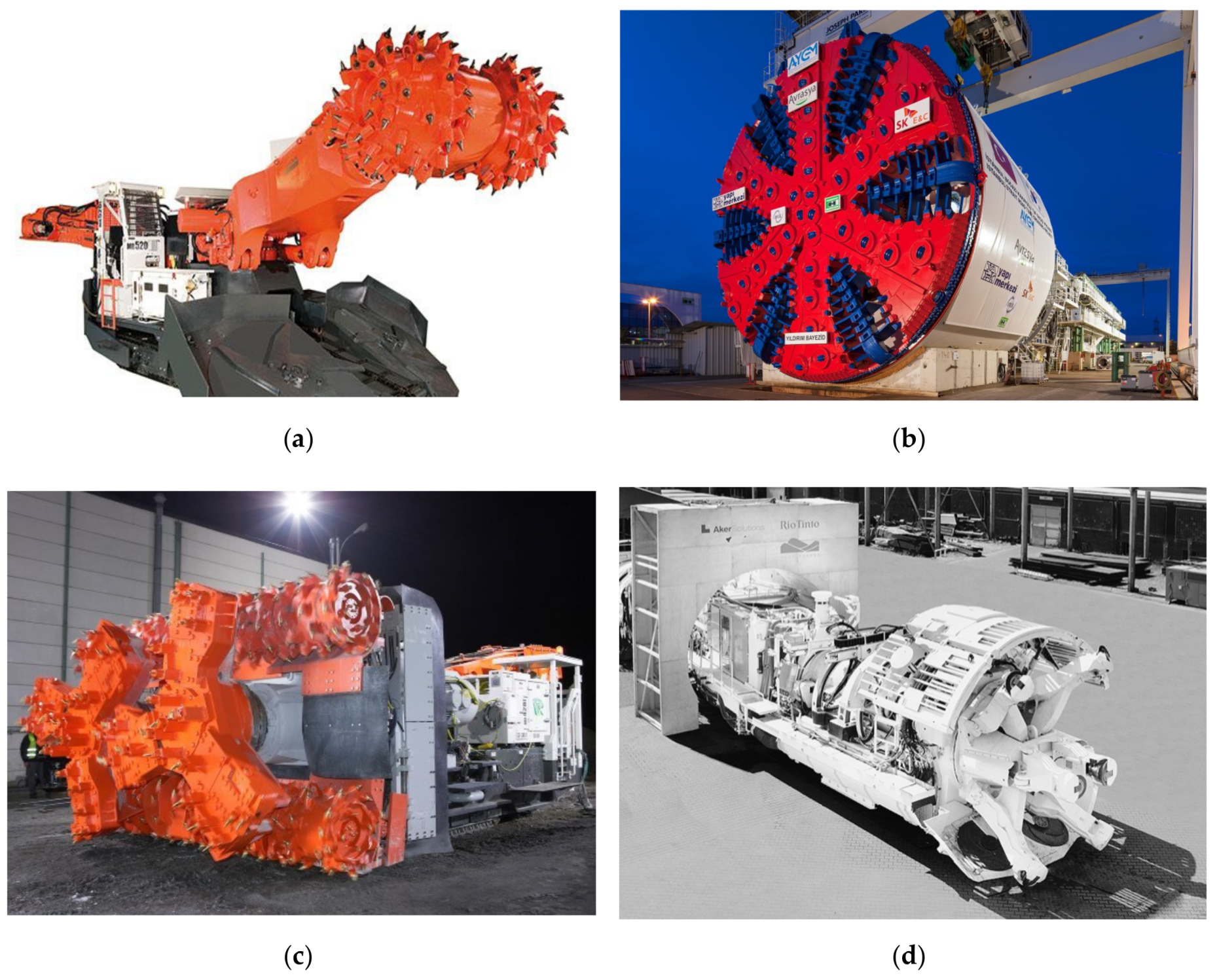
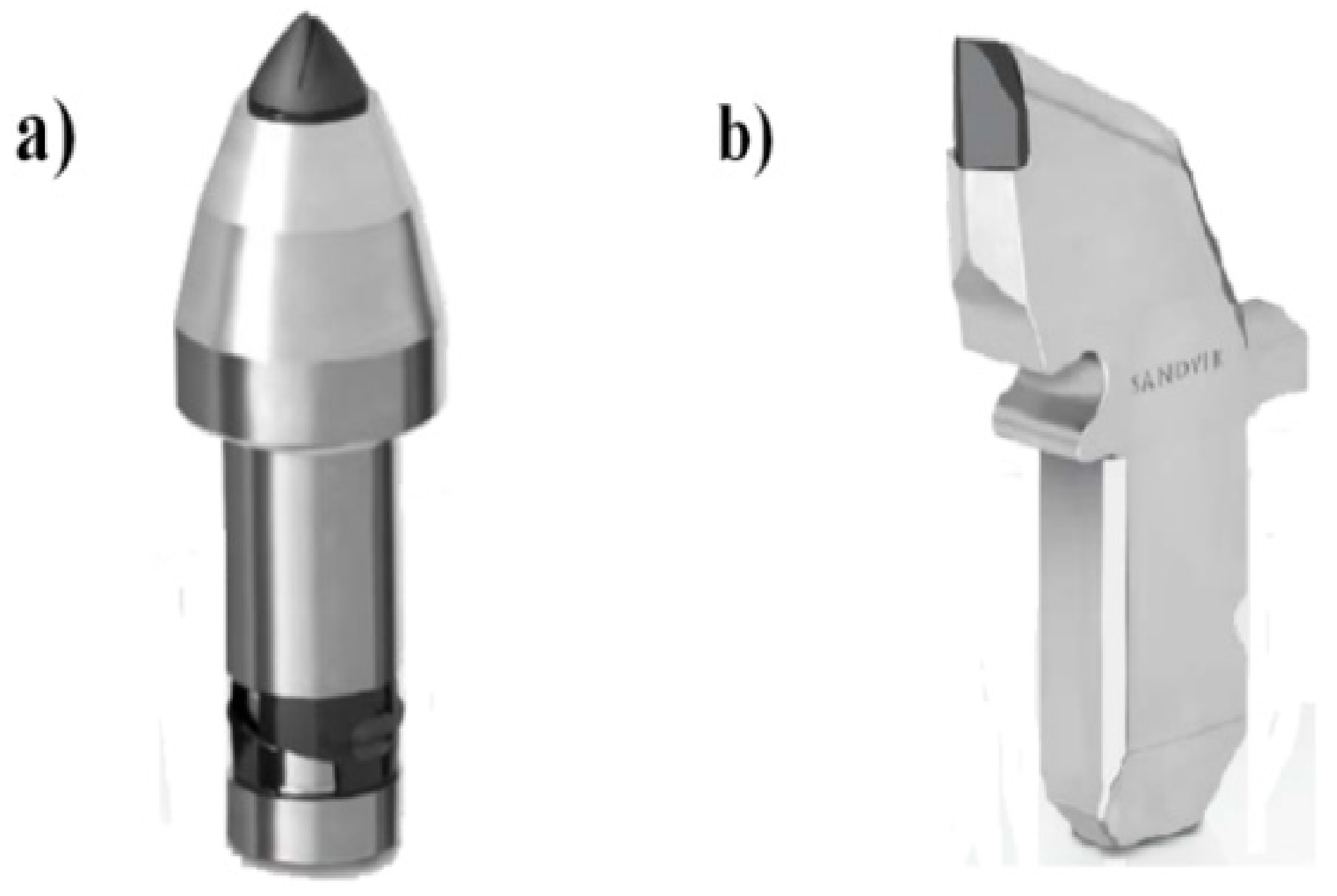
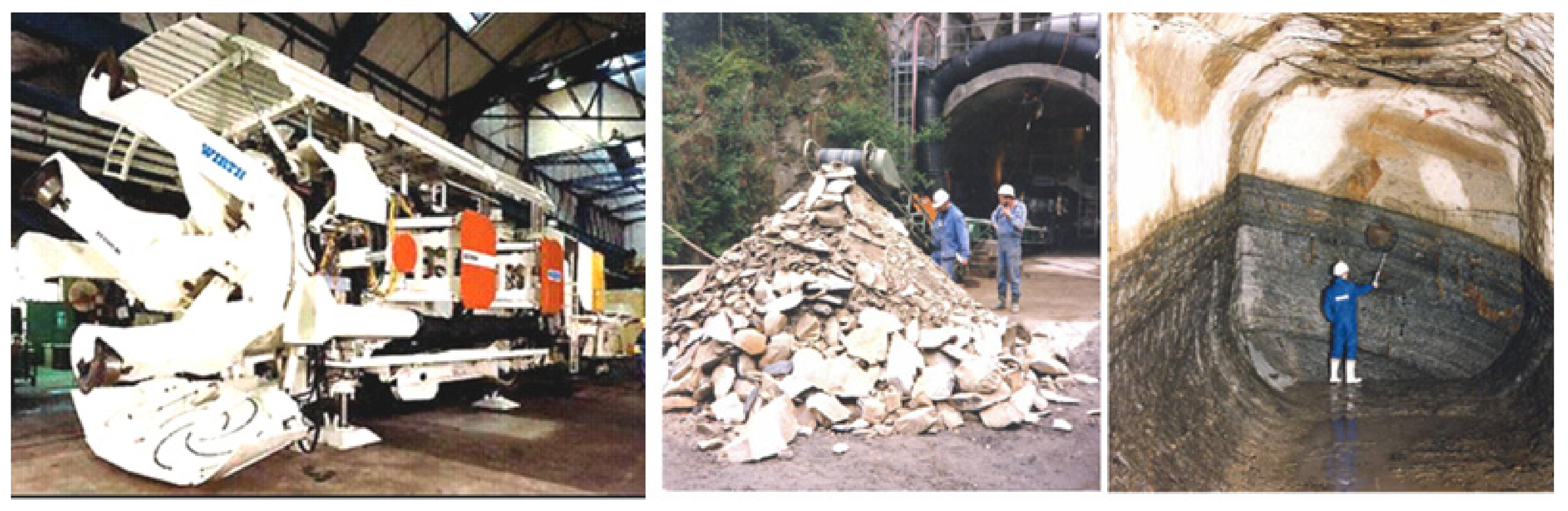
Currently, it is becoming a common practice to drive galleries using mechanical technologies (accounting for 90% of galleries excavated in Poland), including primarily milling. Currently, the most commonly used machines for roadway and tunnel mining in hard rocks are roadheaders, continuous miners, multi-organ borer miners, special roadheaders, and TBMs (tunnel boring machines) with full face mining [
1]. Examples of such machines are shown in
Figure 1. In the case of roadheaders and continuous miners, as well as multi-organ borer miners, cutting tools are used, including mainly tangential-rotary picks (
Figure 1a,c). In the case of some special roadheaders and full face mining machines (TBM), symmetrical or asymmetrical disc tools are used (
Figure 1b,d).
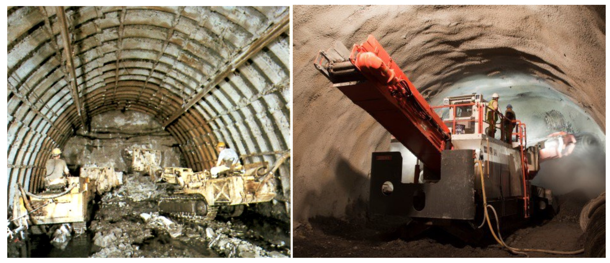
One of the advantages of mechanical face mining is that most of the core operations (rock mining, loading, haulage) is done by a single machine. Consequently, it takes less time to drive a heading, making the miner technology more efficient than the blasting technology, while also helping to achieve a more detailed, desirable envelope of the heading. For heading driving with the use of blasting material several machines or equipment are needed. First of all—a drilling car, then a loader and other machines—a haulage car, a bolting car, belt or chain conveyer etc. It generates huge costs and increased time of single advance. View of a heading face driven using blasting material and a roadheader is shown in
Figure 2.
Moreover, mechanical methods reduce rock weakening around the heading—as compared to blasting-based methods—by substantially diminishing percussive impacts, causing less damage to the rock structure, and providing a better alignment between the support and the envelope, resulting in smaller and more evenly distributed loads. Additionally, they do not generate post-blast gases.
However, mechanical mining has the disadvantage of generating dust and certain application limits related to the upper compressive strength limit involved in cutting. Combined with the high abrasion resistance of such rocks, this causes excessive wear of picks and a lower driving rate.
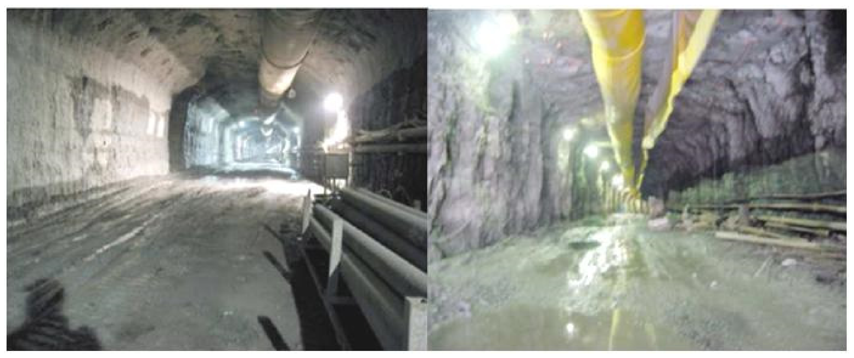
Figure 3 shows images comparing a heading driven with a roadheader and a heading excavated using explosives. In the case of mechanical mining, it is evident that the heading has a clearly more regular envelope and the surfaces of its sidewalls, floor, and roof are much more even.
3. Rock Workability and the Energy Involved in Rock Mining
The mining of rocks with highly unfavorable parameters, especially when driving development workings, has been an issue for the mining industry. This is primarily because the excavated rock material is highly compact and has a large uniaxial compressive strength, often exceeding 120 MPa.
There have been increasing difficulties related to rocks like sandstone and aracenaous shale, as these have an almost homogeneous structure, causing serious problems with their mining, especially when milling-based mechanical methods are employed. An equally important factor is the presence of hard minerals and inclusions in rocks, causing mining tools to sustain rapid abrasive damage and wear. Additionally, in the case of inclusions such as sphaerosiderites, mining works produce heavy sparking [
5,
8,
9,
10]. As already mentioned, milling also generates dust. These three problems encountered in the milling-based removal process are shown in
Figure 4.
The rock mining process depends largely on the excavated rock material and most importantly, on its workability. Rock workability is a property describing a rock’s resistance to mining understood as the separation of a piece of the rock from the solid. The measure of workability is the so-called specific mining energy—that is, the amount of energy required to remove a unit of a rock’s volume. Currently, no commonly accepted method exists to determine or measure workability. There are, however, a number of methods to assess rock workability and these can be basically divided into three groups [
11,
12,
13,
14]:
methods that determine rock strength properties such as the compressive strength σc, and the tensile strength σt;
methods that determine energy indicators such as the Protodyakonov coefficient f;
methods that measure mining parameters directly in the deposit. A method that has been developed for and applied in coal cutting only, in which an appropriate measurement instrument is used to determine the specific cutting resistance Ks or the ratio of the cutting resistance and the cutting depth A [N/cm].
Since these strength and energy measurements are taken in laboratories, they do not take into account the factors that have a significant impact on workability, associated with the rock’s deposition, its macrostructure, the pressure exerted by the rock mass, deposit dampness, etc.
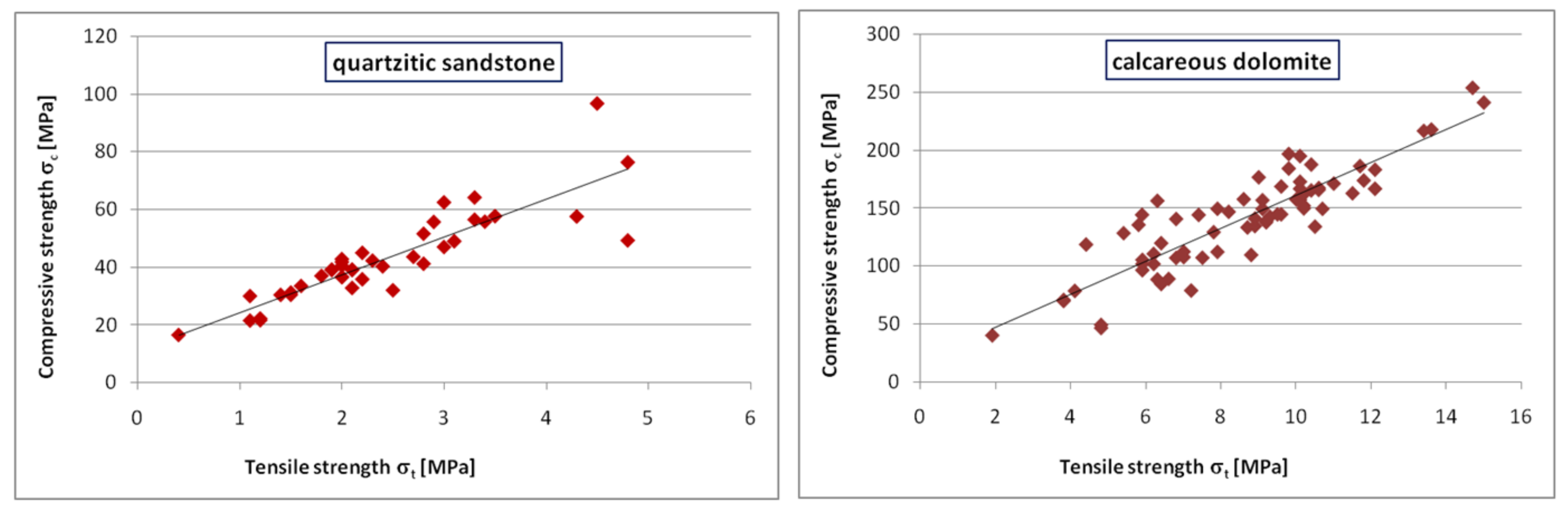
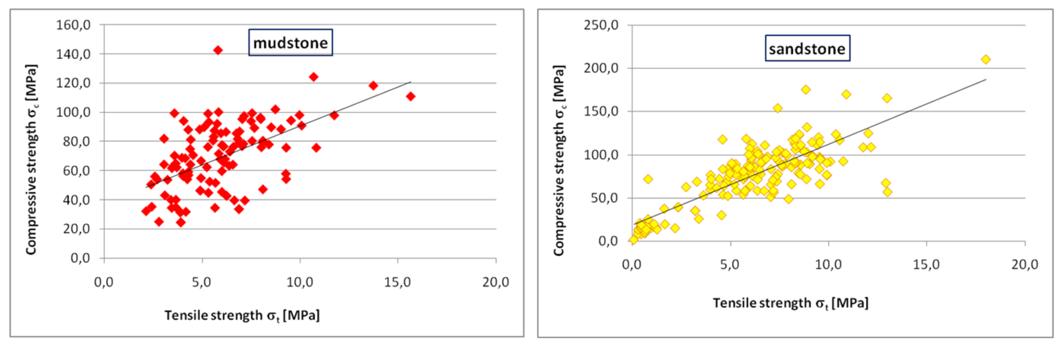
The impact of the rock’s macrostructure on its workability can be noticed when comparing the relationship between the compressive strength σ
c and the tensile strength σ
t. It is assumed that at σ
c/σ
t < 10 the rock is difficult to excavate, while at σ
c/σ
t > 15 the rock is very easy to excavate. Laboratory tests have been carried out at the AGH University of Science and Technology of a number of rock samples collected from Permian and Carboniferous rocks. The results, as illustrated for the selected types of rocks in
Figure 5 and
Figure 6, show that the Permian rocks have a much greater compressive strength σ
c. However, we were told at the mine that there were no problems with the mechanical mining of the rocks in the location from which we took the samples. A comparison of the average values of the relationship between the compressive strength σ
c and the tensile strength σ
t indicates that this relationship is higher for Permian rocks at 15, reaching as high as 17.75. For Carboniferous rocks this value does not exceed 12.5. We also noticed that the trend lines for the Permian rocks are better aligned than for the Carboniferous rocks. We might, then, assume that Carboniferous rocks are more varied mineralogically and petrographically (this is especially true for mudstones), making it more difficult to predict their behavior during mining. Additionally, these rocks have less natural cleavage surfaces. Despite the seemingly easier mining of Permian rocks and their clear bedding, the large compressive strength σ
c of dolomites (140–210 MPa) makes their mechanical mining cost-ineffective. Simultaneously the high strength of rocks and their low proneness to separation (the high RQD index) always help in the heading maintenance [
15].
The impact of the structure of the excavated rock material and the presence of abrasive materials, such as sphaerosiderites and siliceous compounds, on the tool’s load and working life, as well as on mining efficiency, have been described in literature [
16,
17,
18,
19,
20]. The tests were carried out during borehole drilling—first in a rock medium with naturally weakened surfaces and then in rock media with varying contents of SiO
2.
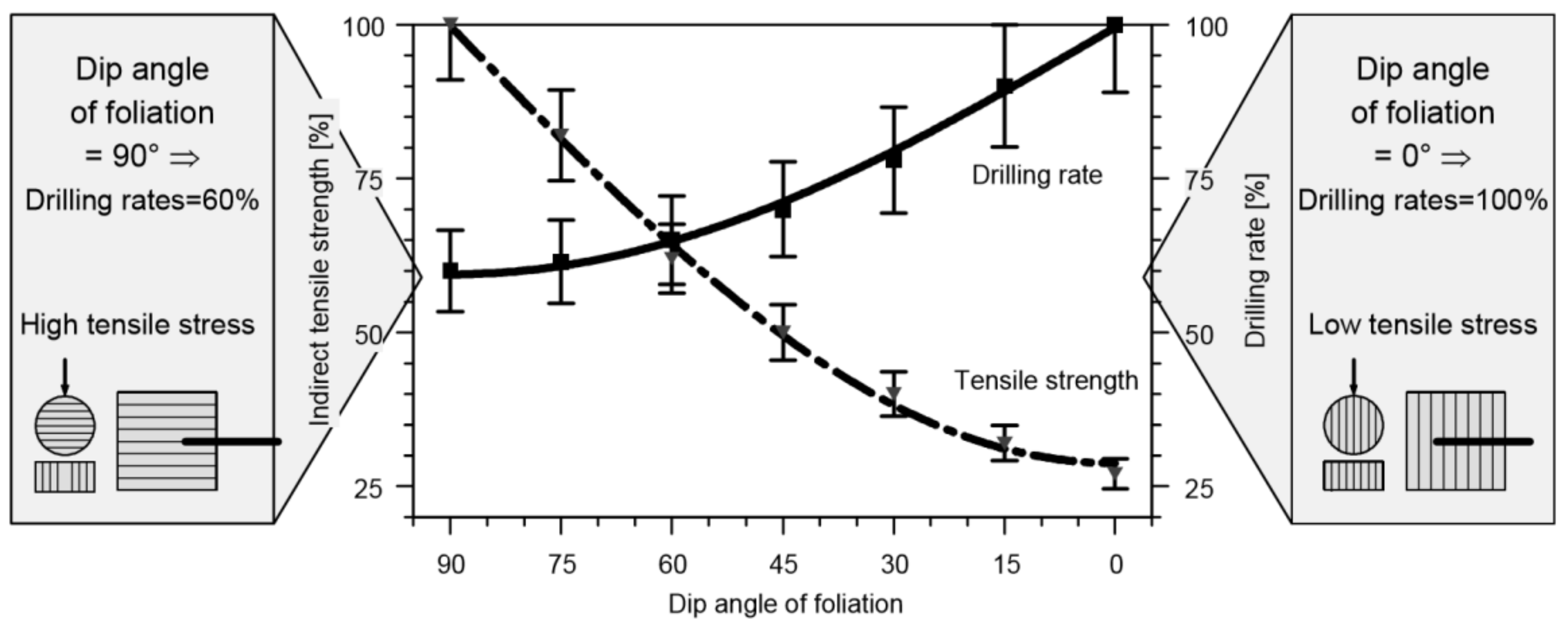
Figure 7 shows the results of phase-one tests. The boreholes were drilled perpendicular and parallel to bedding surfaces and at angles of intermediate values. The tensile strength σ
t for samples whose bedding surfaces were at the same angles of inclination was also determined. It can be noticed that the value of the tensile strength σ
t for samples with layers parallel to the ultimate-force direction is as much as three times lower than for samples with perpendicular layers. This results in an almost 60% increase in the drilling rate [
17].
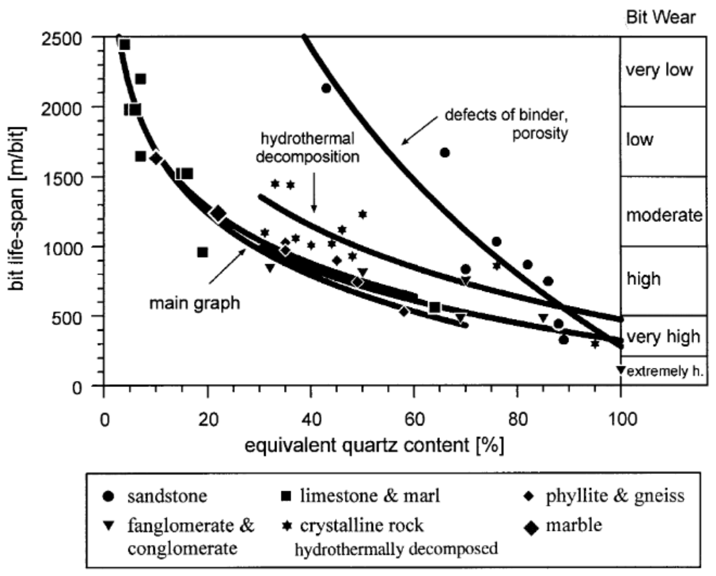
In the case of borehole drilling in rock material with varying contents of SiO
2, the results varied even more (
Figure 8). For rocks with a 60% or higher equivalent content of SiO
2 (sandstone), the maximum borehole length using one drilling tool did not exceed 500 m. For rocks such as limestones and marlstones with the equivalent SiO
2 content of less than 30%, holes were bored with a single tool to a minimum of 1000 m, and to a maximum of almost 2500 m [
13].
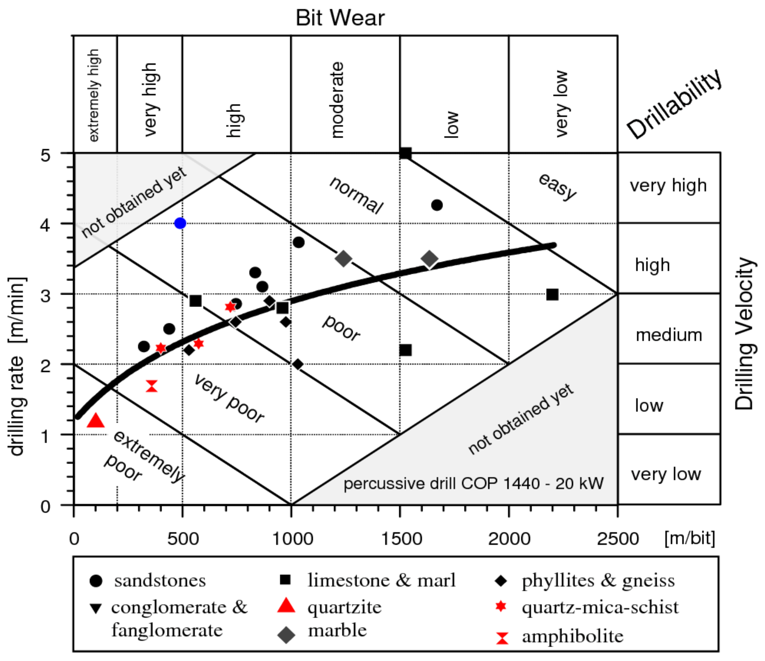
Rock and rock mass properties affected the rock body penetration ability, what in turn, immediately affects bit wear and drilling rate [
2,
16,
17,
18]. Based on the investigation results gathered by Thuro [
17], the chart as shown in
Figure 9 was designed, to calculate the drilling efficiency and the drilling-tool wear for various types of excavated rocks. It is easy see that high abrasive rocks (quartzite, amphibolite) make the biggest problem in effective drilling.
By acting on the rock, a drilling or cutting tool or a tool that excavates material through static pressure, causes to varying degrees, rocks to be crushed, certain rock volumes to be broken down, elements of varying sizes to chip off, and ledges to break off. The contribution of the individual forms of rock disintegration depends on the mining type, the tool’s geometry, its operating parameters, and also on rock properties. During mining, loose grains are undergoing secondary crushing, leading to energy losses which are impossible to calculate with sufficient precision.
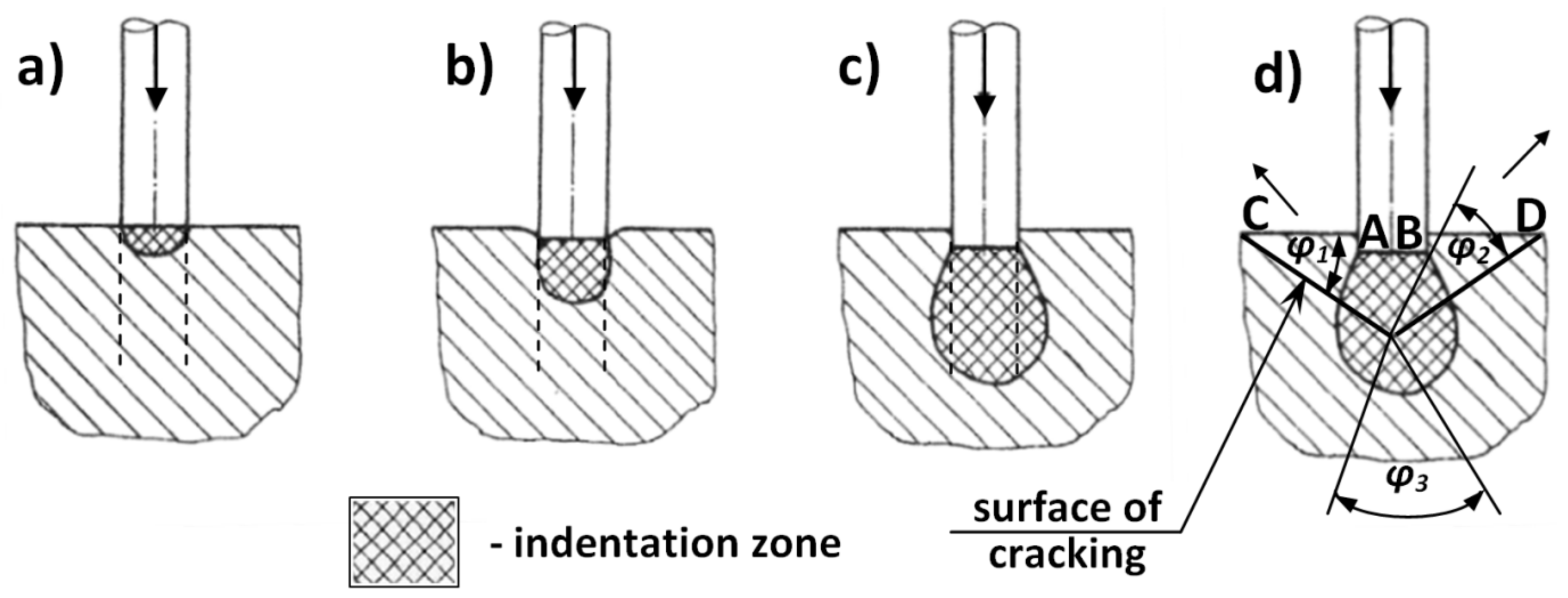
Based on observations and the analysis of the rock mining process, a general theory of mechanical rock mining was formulated. In this theory it posits that the so-called indentation zone plays the key role in the process of rock disintegration [
21]. This is a universal theory, as it applies to both static and dynamic action on the rock and also considers the phenomena associated with the use of tools of different shapes. Using this theory, the process of rock disintegration can be illustrated on the example of a pin penetrating the rock (
Figure 10) [
21].
As the force increases, so does the indentation zone’s range of depth (
Figure 10b), although the reduction in rock volume is initially set off by elastic deformations of the surface. With the load increasing further, the rock shear strength along the pin’s circumference (dotted line) is overcome (
Figure 10c), and the pin penetrates slightly into the rock. The indentation zone reaches deeper, while the cracks along the pin’s circumference do not reach deep. As the load exerted by the pin increases further, the tensile stress occurring around the indentation zone causes initial internal cracks in the weakest spot (
Figure 10d).
These cracks are directed towards the free surface, and since the rock resistance has been overcome, the cracks that occurred along the pin’s circumference produce from the indentation zone a wedge, or an ABO cone, which causes rock elements to break off along the OC and OD lines. The wedge itself is crushed in the process. With sufficient energy or force, the excavated elements are forced outside. This process is characterized by the angles φ1, and φ2, depending largely on rock properties and, to a lesser degree, on the tool shape.
The indentation layer theory [
21] provides a convincing explanation of the mining process. The range and shape of the indentation zone varies between individual processes depending on the pick geometry and direction of the main component of the force exerted by the tool on the rock, causing its failure. This direction may be either tangential or perpendicular to the rock. The former case involves cutting, while the latter involves crushing.
Soft and brittle rocks, as well as rocks with naturally weakened surfaces, such as coal and salt, are usually excavated by cutting. At an appropriate pick angle, the indentation range is small here, and the slow progress of the process causes cracking in the weakest spots—i.e., with the maximum utilization of weakened surfaces. This would explain the low energy demand and high efficiency.
Cutting-based methods are not appropriate for rocks that are difficult and very difficult to excavate, including especially those that contain silicon (its compounds and derivatives) and volcanic-rock inclusions. Such rocks require the use of large cutting forces. The parallel movement of the pick and the related friction between the rock and the pick surface cause pick blunting and wear, resulting in an instant increase in cutting resistance.
The forces that cause the tool to move and its pick to penetrate the rock can be generated in two ways—by applying a very large static load on the tool, or by converting the kinetic energy of the same tool or of the piece that hits the rear of the tool, the so-called ram, accelerated to high speeds, into the impulsive impact energy.
The primary purpose of rock mining is to separate from the rock solid the largest possible rock pieces using as little energy as possible. Rock mining is generally measured using the specific energy
Ew.
where:
Eu—energy supplied to excavate the rock, J.
V—volume of the excavated rock, m3.
Thus, the specific energy expressed as Equation (1) is the energy required to excavate a unit of a rock’s volume. The lower the specific energy, the more efficient the process. However, using specific energy as a measure of process efficiency should be approached with caution.
During rock mining, energy is used to break the rock’s structure by creating cracks and craters. Hence, it seems reasonable to assume that in an efficient process, the supplied energy
E will be proportional to the newly created surface (~
d2, where
d is the linear dimension of the newly created rock grain). Assuming further that the dimensions of the rock excavated by impacts of different energies, or by loading of different magnitudes, have the same shapes, the volume of the removed rock piece
V will be proportional to its linear dimensions raised to the power of three (~
d;). Thus:
Hence, the specific mining energy is reversely proportional to the dimensions of the removed rock piece. This means that as the grain dimensions increase, the energy required to excavate a unit of the rock’s volume decreases. This is commonly known as Rittinger’s law.
Some interesting conclusions can be drawn if one assumes that the energy required to break the rock—for instance, through high-energy impacts—is proportional to 1/
d, and also that the dimensions of the removed rock piece have the same shape despite the increase in energy. If:
then:
and
The practical interpretation of Equation (4) is that a machine which hits the rock, for instance, 20 times a minute with the impact energy of 10 kJ can remove rock amounts 10 times larger than a machine with the same capacity but hitting 2000 times per minute with the energy of 100 J. This is because not all of the mining energy
Eu is consumed to excavate the rock, as some of it is used to create new surfaces. In addition, some of the energy will be absorbed as the kinetic energy from broken-off pieces, as well as noise and heat energy [
21].
Furthermore, as the mining energy increases, the specific mining energy decreases, although the increase is smaller for larger mining energies. This tendency can be explained by the existence of the so-called energy threshold, whose value depends on the rock’s strength parameters, and which triggers the process of overall cracking and structural disintegration of the rock when exceeded.
4. Mechanical Mining Using Cutting Tools
Mechanical face mining using cutting tools usually involves roadheaders. Here, the cutting tools on a boom-mounted cutting head remove rock pieces from the rock solid. Face mining takes place through milling done by the cutting head, usually a transverse head, or alternatively a longitudinal one, most of them fitted with point-attack picks, and less often with radial picks. The head is mounted on a boom, usually allowing the excavated face to be profiled from a single position. The cutting tools remove rock pieces from the solid, and the muck falls onto the loading boom at the front of the roadheader [
5,
11].
As already mentioned, the cutting head features enclosed cutting tools—rotary-tangential picks or radial picks (
Figure 11).
Mining by cutting involves a wedge-like or conically shaped tool acting almost parallel to the rock surface. The tool has a holder for mounting on the cutting head and the working part, which does the cutting, featuring a cemented-carbide insert. The tool has the following angles [
19]:
α—clearance angle,
β—pick angle, and
γ—angle of attack, the sum of which is
α +
β +
γ = 90°. The head-mounted tool moves along with the cutting head relative to the machine body. The cutting produces a fissure with the depth
g. In order for the machine to cut the rock instead of crushing it, the clearance angle must be
α > 0.
Depending on the physicochemical properties of the excavated rock and the pick shape, in order to cut the rock to the depth g, the force P must be applied to the pick to counter the force coming from rock mining resistance. The force P exerted on the pick can be distributed into three constituent forces exerted in three perpendicular directions: the force exerted along the fissure, called the cutting force Ps—which plays the key role in the cutting process, the force exerted perpendicular to the fissure bottom—the pressure force Pd that counters the friction force produced by the cutting force Ps, and the force that is perpendicular to them—the lateral force Pb.
Since rocks are more brittle than plastic, cutting them produces muck composed of spalls and dust instead of continuous chips, as with metal cutting. The pick’s movement creates a fissure whose shape, and especially bottom, corresponds to that of the pick (the width b and the shape of the cutting edge).
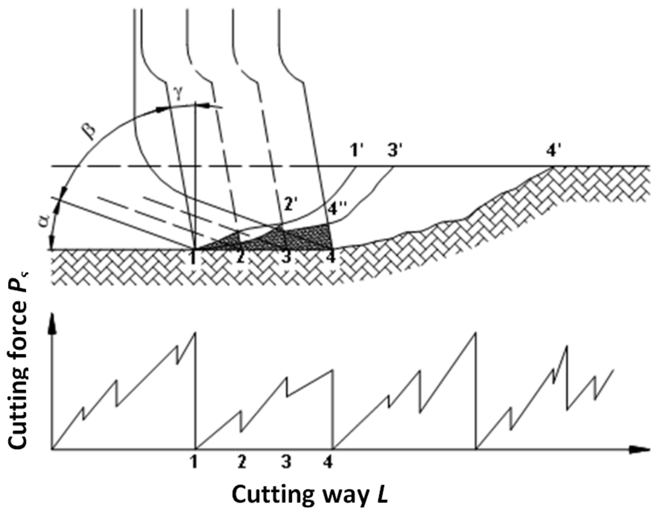
Once a bigger grain breaks off (
Figure 12), the pick drives with its cutting edge into the frontal, inclined wall of the fissure, cutting a certain amount of the rock (the dotted area), with a gradual increase in the cutting force
Ps. The resulting complex stress situation in the rock causes tensile and shear stresses that are more efficient in rock disintegration than compression stresses. Once the contact area increases to a certain value, the cohesion of the rock is overcome, causing the hatched area of the spall to break off, and a certain amount of the crushed rock to be discharged abruptly, with the cutting force
Ps decreasing. As the pick moves further, the rock is once again crushed, with the cutting force and the contact area between the pick and the rock increasing again until the next, larger spall breaks off. The time between such break offs of larger spalls is called the cutting cycle.
Currently, it is more common to use conically shaped picks that can rotate in the holder (conical rotary-tangential picks), especially when excavating rocks with compression strengths larger than that of coal—i.e., when driving stone and stone-coal roadways. The geometry of these picks is closely associated with the mining process. The pick angle is determined similarly to that of radial picks. The position of the tool in relation to the cutting line depends on the setting angle and the lead angle.
The conical shape of the pick influences the spatial shape of the crushing area, as unlike in traditional picks, by design, the pick comes into point contact with the rock, not into linear contact. Consequently, the crushing area has a smaller range and the unit loads on the rock are larger, which is important for compact-rock mining. Some researchers claim [
11,
21] that the “pointed” end of a conical pick allows greater concentration of the transferred energy and easier initial gap penetration, and also facilitates intensive lateral rock crushing, thus supporting mining [
22]. These improved cutting conditions can be attributed to the sufficiently wide “fissure”, in which the pick encounters little resistance during its rotary cutting movement. Another important design assumption was that during its rotary movement, the conical pick wore out consistently along the entire cone sleeve. Consequently, the pick’s cone angle and cutting ability remain almost the same during the cutting action.
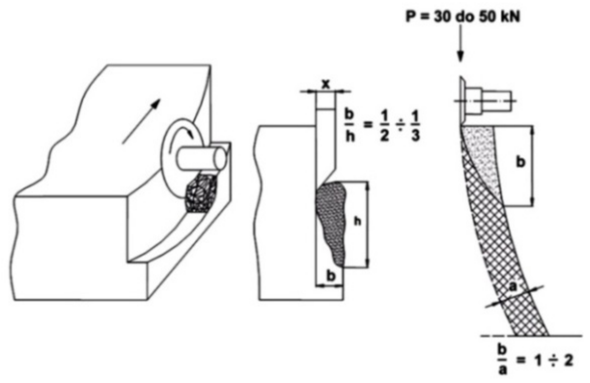
Pick wear is significant for the efficiency of the cutting process. This phenomenon is inextricably linked to rock disintegration, but it is also dynamic in nature, its patterns and intensity varying as a function of time. Wear occurs when the pick loses some of its volume (through abrasion or micro-cutting) due to mechanical fatigue (resulting, for instance, from dynamic loads) or thermal fatigue [
22,
23,
24]. In other words, it is a change in the pick’s geometry and its contact area with the rock.
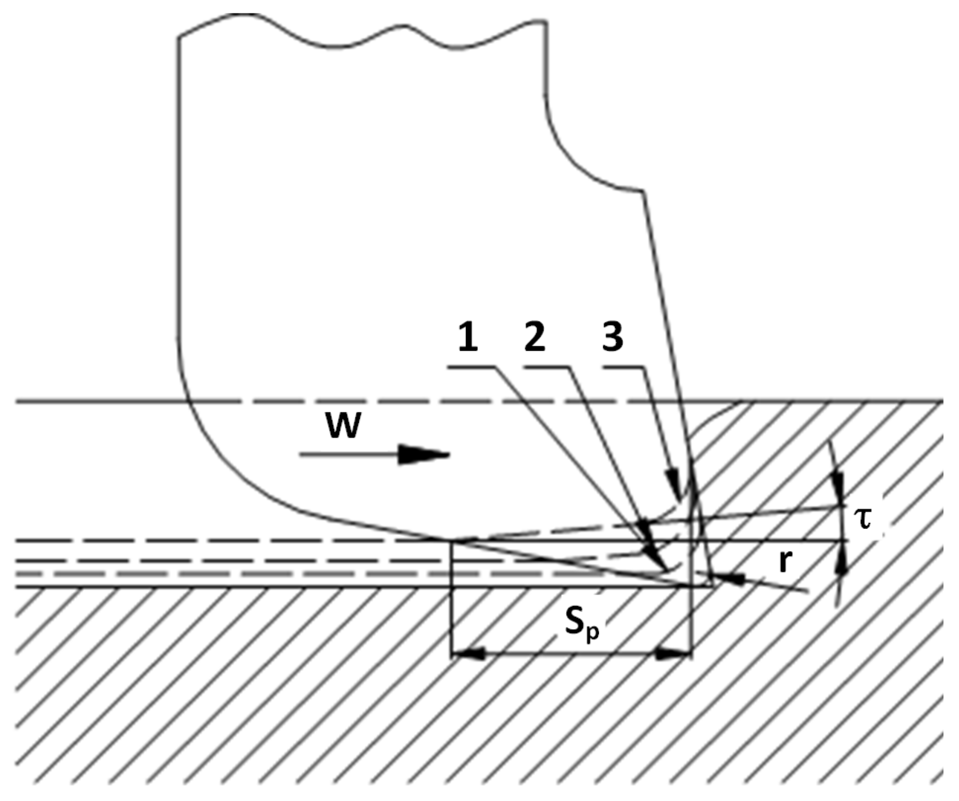
Figure 13 shows the usual wear pattern of V-shaped picks used in rock cutting [
11,
21]. Initially, wear results in an increased radius
r of the pick’s rounded edge (point-1). Subsequently, the contact surface gradually flattens, and the width
Sp of this flattened area is considered a measure of pick blunting (point-2 and 3). This flattening is inclined in relation to the tool’s actual movement direction
w at a small angle of τ. Pick wear is also manifested as splintering and micro-splintering on the tool face and flank face. With a blunted pick, in order for the cutting action to occur, the cutting depth
g must be larger than the pick’s rounded edge radius
r [
11,
21].
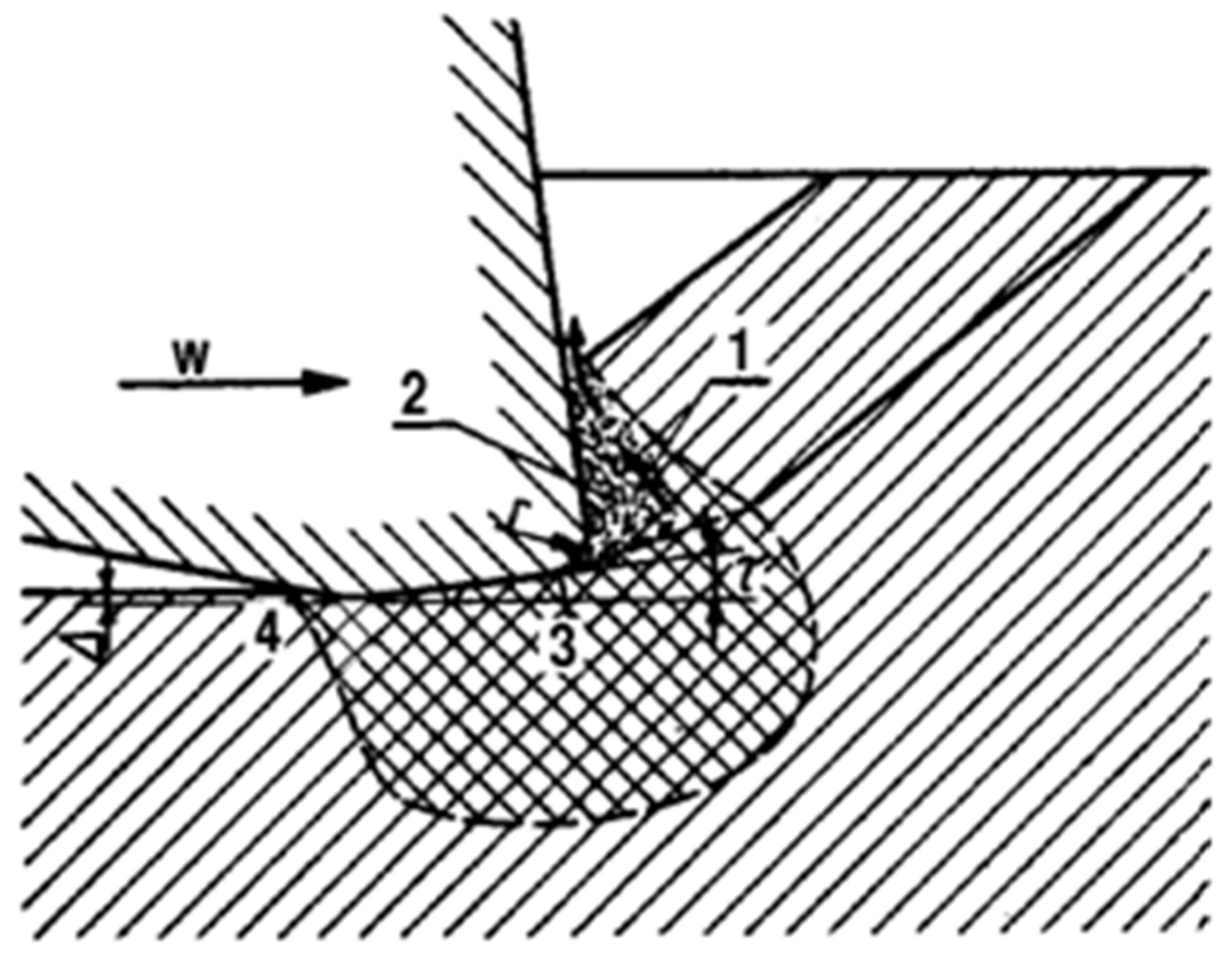
When cutting is done with a blunted pick (
Figure 14), the rock indentation zone occurs both in front of and underneath the pick. Crushing must occur before the pick as the contact area between the tool face and the rock increases. The crushed rock (area 1) is forced sideways or upwards, but due to the pressure from the tool face, it carries a small layer (2) of crushed rock residue, similar to the build-up from metal cutting. This residue is temporary and successively replaced [
11,
21].
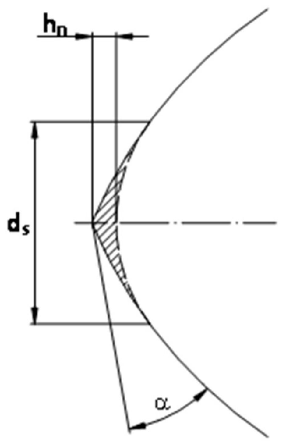
When the pick is heavily blunted, these reactions are very strong, and as the blunting progresses, the pressure force
Pd increases substantially, while the cutting force
Ps increases only slightly. In the case of a rotary-tangential pick, instead of the pick wear width
S on the side of the tool face, we can use the radius
ds of the rounded edge due to blunting (
Figure 15), under the assumption that wear occurs uniformly, meaning that it causes only pick shortening, without any changes in the pick’s angle.
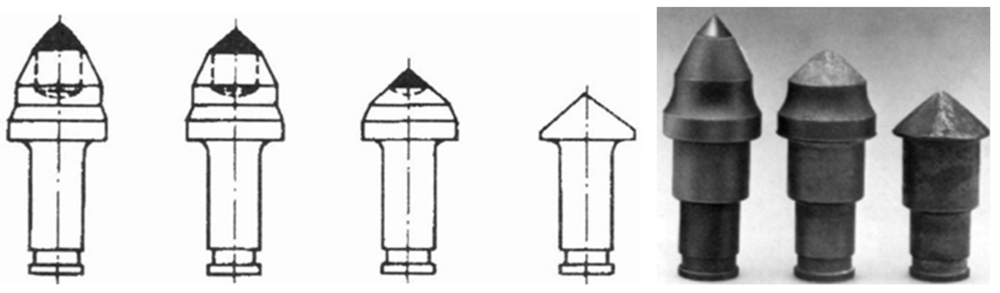
The now-prevailing view is that the mechanism behind the blunting of a rotary-tangential pick is different and closely linked to the pick’s rotation [
10,
25]. Blunting mainly leads to changes in the pick’s shape, causing the pick angle
ß to increase gradually until it reaches twice the value of the setting angle
δ. As a result, the angle of attack
γ usually has a negative value, and the clearance angle
α is reduced to zero.
Figure 16 illustrates the phases of an “ideal” wear process for a rotary-tangential pick, showing images of such wear obtained in a laboratory setting.
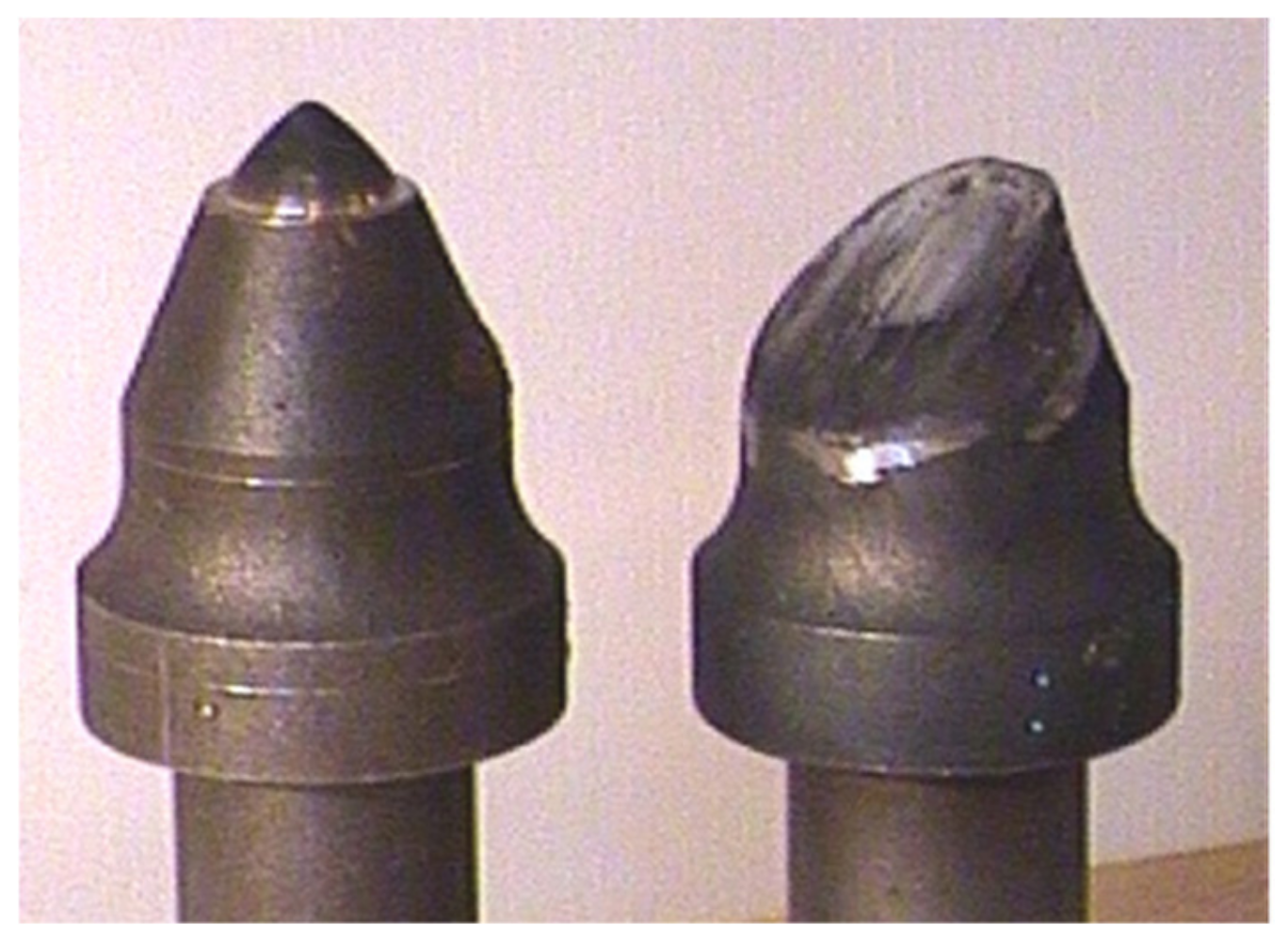
Evidence from industry practice shows, however, that the wear process of these picks is much more complex and varied [
8,
23,
27,
28]. Mechanical (splintering and insert breakoff) damages or damages due to mechanical or thermal fatigue (usually cracking), as well as asymmetrical abrasive wear (caused by the pick jamming in the holder) or by insufficient torque, are the most common types of rotary pick wear, as the probability of a rotary movement of the pick is estimated at 50% [
8]. Pick rotation plays an essential role in pick wear. In compact rocks, primarily sandstones, the pick is seized in the socket, resulting in abrupt and asymmetrical pick blunting (
Figure 17). This happens during the operation of roadheaders when excavating stone and stone-coal roadways. Such a wear pattern makes it pointless to use conically shaped rotary picks, and also leads to increased pick loads, including especially from increased pressure force, dust generation, and cutting-head vibration.
Roadheader heading mining in rocks with a uniaxial compression strength of more than 150 MPa was found to result in extensive cutting tool wear, in extreme cases reaching five picks per 1 m
3 of cut material. As a result, the driving efficiency decreases substantially, and the costs rise sharply. It is considered cost-effective to use tools with a wear level of about 0.2 pick per 1 m
3 of cut material [
29].
A similar problem is encountered when excavating coal using longwall shearers. The degree of the tool’s wear is very important. Studies [
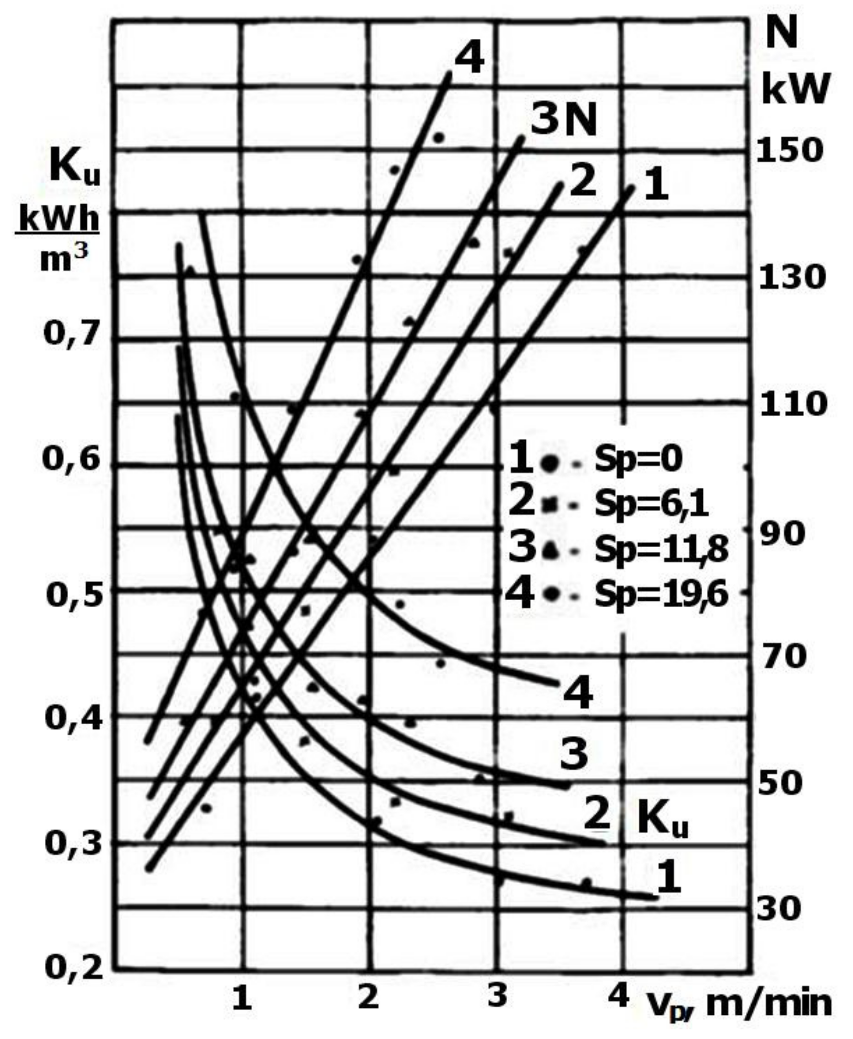
30] have shown that pick blunting, in this case of a radial pick, is a very significant factor in power consumption and, more importantly, in specific power consumption, in relation to the volume of the excavated rock.
Figure 18 shows the relationship between the power consumption
N and the specific power consumption coefficient K
u as a function of the longwall shearer’s advance rate
vp for four radial-pick blunting values S
p in millimeters (see
Figure 13). Compared to the brand new pick, the pick blunted up to 19.6 mm and the power consumption
Ku is more than double. The charts show that as the advance rate
vp grows, causing an increase in the cutting depth, and the impact of pick blunting becomes significantly stronger. The bigger blunted surface increases heat dissipation and, by extension, increased tool heating, and a sparking tendency.
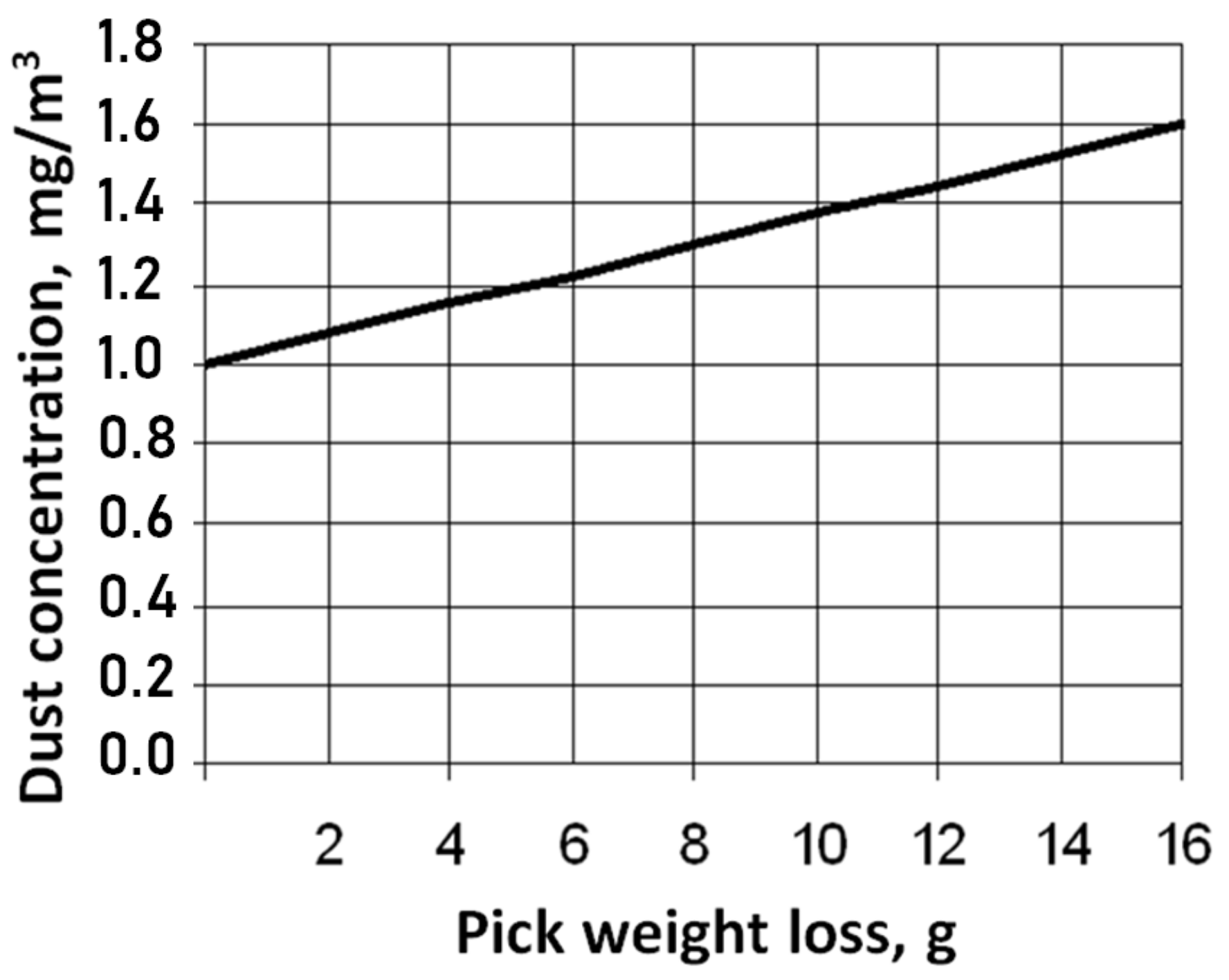
Tool wear is inevitably accompanied by a larger fragmentation of output, creating more dust. This is associated with the above described processes. When cutting is done with a blunted pick, the rock compression and crushing zone occurs both in front of and underneath the pick. It is several times larger than in a sharp pick. In-service tests have shown that even an insignificant increase in tool wear is enough to cause increased dust generation, by 30–70% [
31,
32]. This proves that smaller tool wear has very important practical implications.
Figure 19 shows the impact of wear-related pick weight loss on the concentration of respirable dust when excavating with the use of rotary-tangential picks.
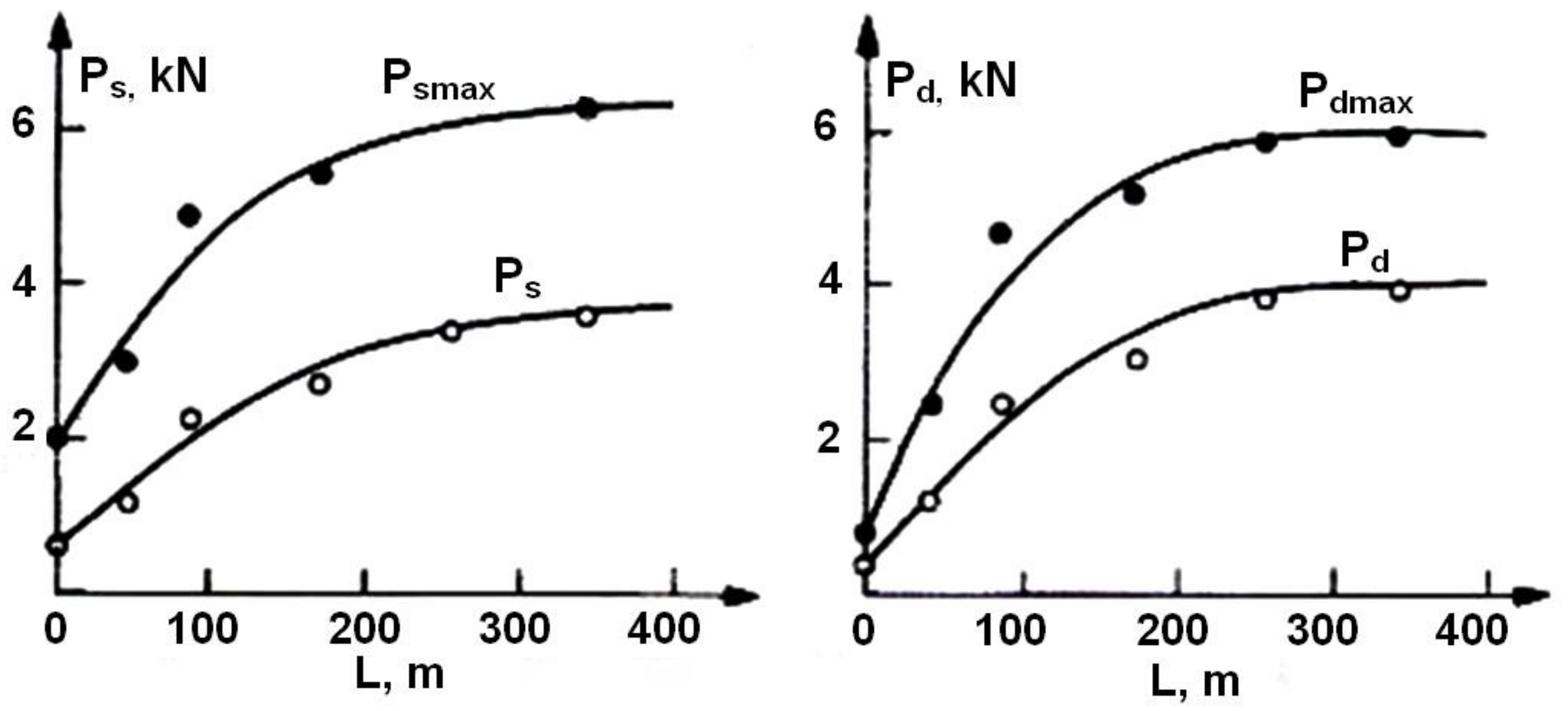
The wear of a V-shaped pick increases as the cutting path becomes longer, incidentally resulting in increased loads on the pick. In their studies Kenny and Johnson [
33] determined the impact of the cutting-path length on the cutting force
Ps and pressure force
Pd. This is illustrated in
Figure 20.
5. Mechanical Mining Using Disc Tools
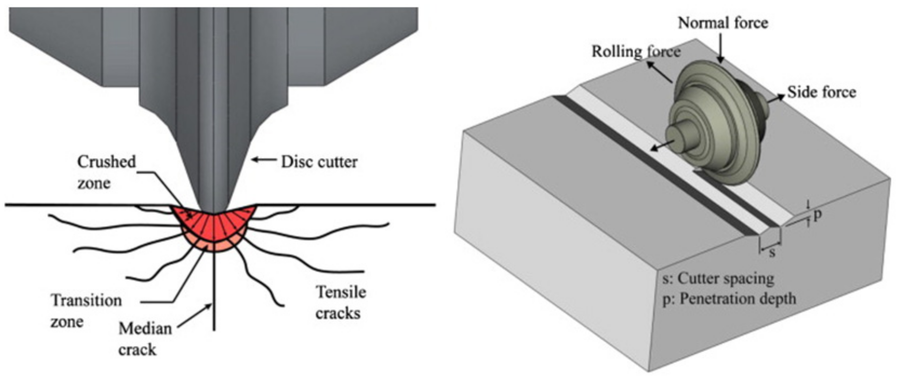
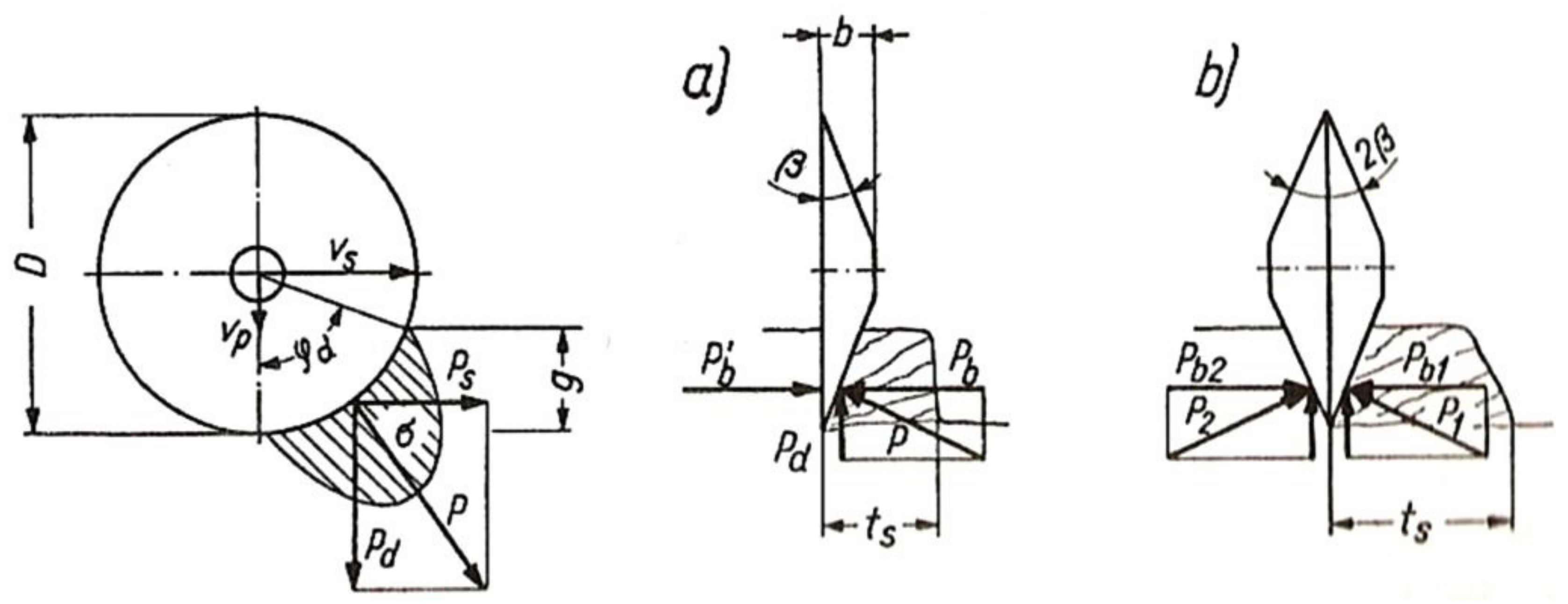
In the case of rocks that are very difficult to excavate, an alternative to cutting tools is mining by applying static normal force to the surface of the rock by disc tools (discs).
Figure 21 and
Figure 22 show how this method works. In this method, the disc’s edge, with a V-like, symmetrical or asymmetrical shape of its cross-section in the plane normal to its edge, is pushed into the rock with a force of
Pd, perpendicular to its surface. As a result of this force, the compressive strength of the rock is locally exceeded, with the disc driving into it to the depth
g. In addition, the tangential force
Ps is applied to the disc handle, causing the tool to move along the surface of the rock. Due to
Ps and
Pd forces, the disc puts the rock under pressure coming from the resultant force
P along a circumference corresponding to the angle
φd (
Figure 22). The disc is mounted in a rotary holder, enabling the disc to rotate on its axis with the angular speed
ω, rolling in the rock to produce a notch [
5,
34].
The basic advantage of this method is that it radically reduces the role of friction forces by using the rotary movement of the tool. Moreover, due to rotary movement, each section of the disc’s edge remains in contact with the rock for a short period of time, during which it does the work required to achieve the target notch depth. This results in smaller energy losses, and better heat dissipation conditions on the disc’s edge, reducing the side effects of mining, such as sparking due to local increases in temperature, or dust generation, and extending the service life of the tool.
According to Innarauto [
35] during rock cutting with the help of a disc three distinct phases can be identified:
After the specific indentation load is reached which depends on the rock type (here is diorite with compressive strength of 234 MPa) the rock piece chipping starts (the visible peaks on the line) with minor increases of indentation load (
Figure 23).
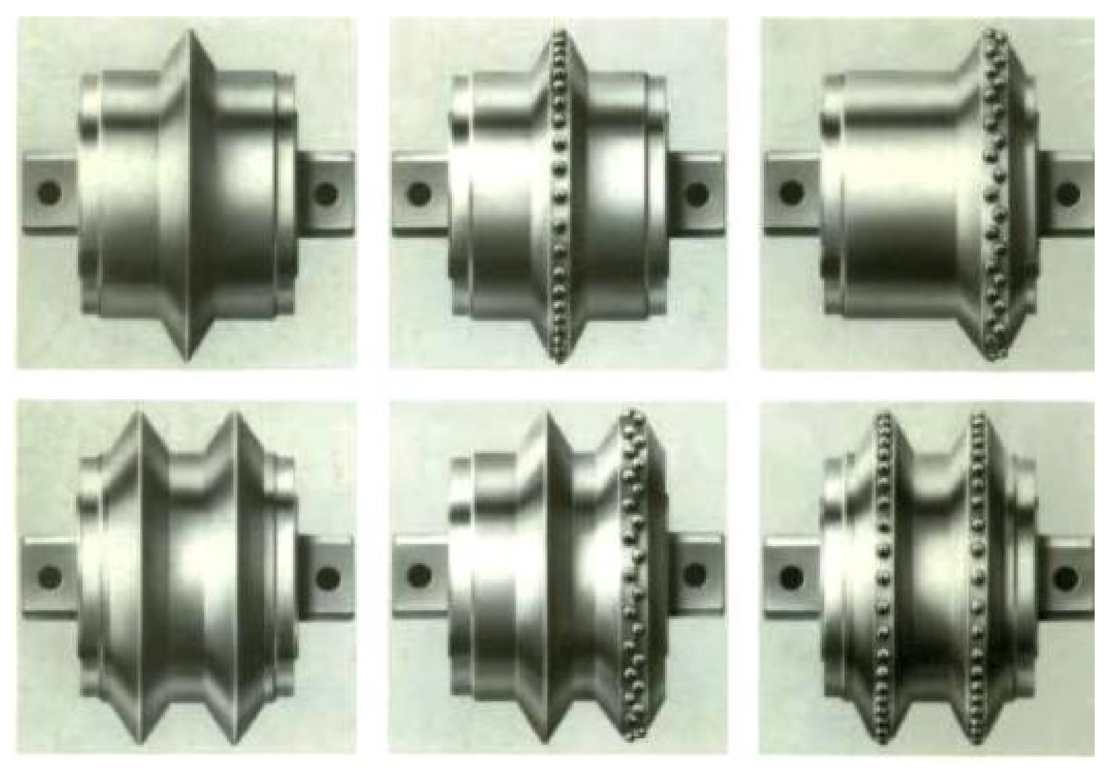
There are three types of symmetrical disc tools: smooth discs, discs fitted with inserts, and toothed discs in single-, double-, or tripe-bladed versions. The first two, shown in
Figure 24, are the most common. They can be as large as 500 mm in diameter [
3,
36,
37]. Smooth single-bladed disc tools can advance up to several kilometers of roadways or tunnels without visible wear. By comparison, the service life of a cutting tool is no more than several cubic meters of output.
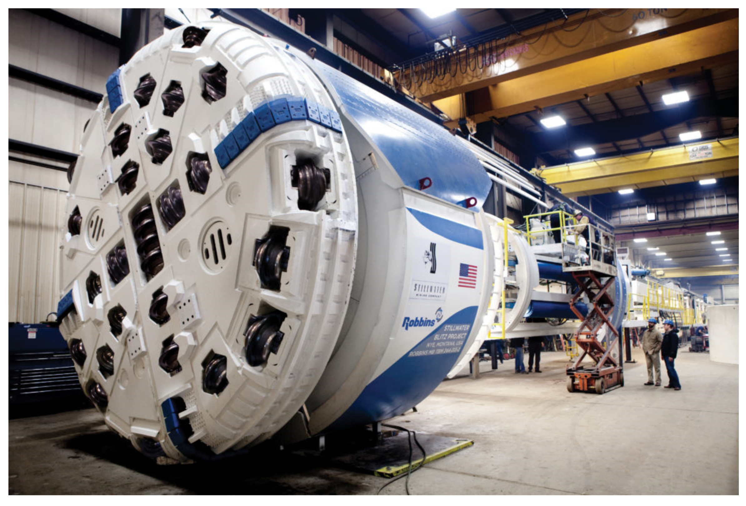
The disadvantage of mining by static crushing is the need to ensure a high pressure force exerted by the tool. Stone rock disintegration is the result of the rock’s uniaxial compression strength being exceeded. According to available data, the value of the pressure force per disc tool, as shown in
Figure 25, can be as high as 300 kN. A large number of disc tools on the mining head produce tremendous combined pressure force (up to 25,000 kN) and lateral spreading force that is multiple times greater to ensure operational stability of the TBM. The mining machine must transfer the reactions coming from the mining head and stabilizing struts. These large reaction forces are the result of the considerable weight (up to 3500 Mg) and size of the machine (a TBM can be as long as 400 m).
Figure 25 shows an image of the mining head of Robbins TBM. This results in the limited use of this type of machinery for driving with a very high advance. Only in this case very large costs connected to their production and assembly in the mining excavation can be paid back [
3,
36,
37].
A number of other concepts have been proposed regarding the use of asymmetrical static discs, the underlying idea being to use the disc as a chipping tool. This creates an opportunity to take advantage of rock tensile strength, which is several to more than 10 times smaller than rock compressive strength, a distinctive feature of rocks. The disc tool acts on the rock tangentially to the surface of the excavated rock, similarly to a cutting tool, the difference being that the rolling movement of the disc effectively eliminates sliding friction in favor of rolling friction. This method is called undercutting [
6].
The principle of the undercutting method is mining a rock by its chipping off in static direction to a free rock surface. The disc tool acts on the rock tangentially to the surface of the excavated rock, similarly to a cutting tool, the difference being that the rolling movement of the disc effectively eliminates sliding friction in favor of rolling friction.
Figure 26 contains a diagram showing this mining method. Applied in this way, disc tools reduce energy consumption and the pressure force. Effectively, mining machines can be designed with accordingly lower energy demands and to less strict stability requirements than machines fitted with traditional discs, operating perpendicular to the surface of the mined rock [
6].
This method, however, involves highly variable lateral forces on the edges of disc tools. This is probably the reason why it is difficult to properly take over the reaction on disc tool holders and their bearings. Hence, after preliminary research on the machine developed by Wirth, equipped with swinging and rotating arms, which provided positive results at the end of the 20th century, the further development of the machines using this method was discontinued for several years [
38].
Figure 27 shows the Wirth machine using the undercutting method and the effects of its work.
Mining tests using this method were conducted at DMT, Germany, on the Ruhr’s carboniferous sandstones with the following parameters:
compressive strength 120–140 MPa;
tensile strength 10–13 MPa;
point load test 8–10 MPa;
quartz content up to 74%.
The mining head of the machine was fitted with discs 450 mm in diameter. One disc was mounted on each swinging arm. The arms were hydraulically actuated, with the hydraulic cylinders exerting active mining force, while the entire head made rotational movements such that the movement trajectories of individual discs created spirals. With the machine’s installed driving power of 70 kW, a penetration depth of 6 mm per rotation and disc was achieved, with a swath (the predefined cutting depth) of 120 mm. This corresponded to a unit mining efficiency of 3 m
3/h per disc. For comparison, traditional disc mining using TBMs provided a mining efficiency of only about 1–2 m
3/h. The solution also had a very important advantage of there being no visible and measurable wear signs on the discs [
38].
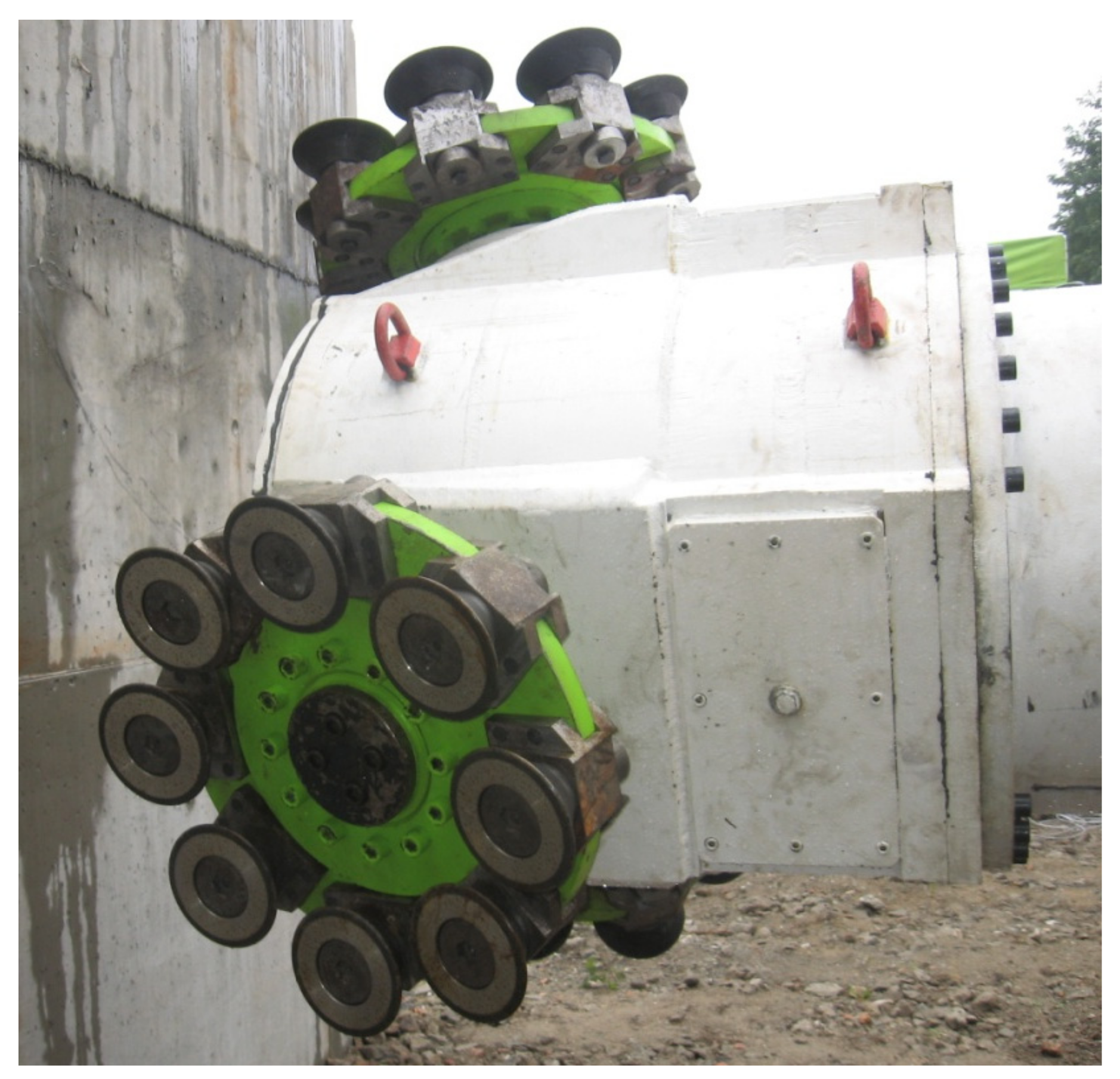
All this speaks in favor of the method and its underlying solutions should guide further engineering of mechanical machines for driving roadways in compact rocks. The concept of the undercutting method was developed at the Department of Mining, Dressing and Transport Machines, AGH University of Science and Technology, in order to design an innovative mining head, fitted with mini asymmetrical disc tools [
39].
In this design the motion of the tools will be forced, causing them to excavate the rock along a complex movement trajectory. It allows the mining lines of individual disc tools to be crossed, and facilitates the mining of compact rocks by breaking off rock furrows. The design is expected to reduce the energy consumption involved in the process [
40]. Disc tools were mounted on separate plates that could rotate on the mining head body, and were propelled independently. Works were undertaken in cooperation with the REMAG Company to adapt the new head solution to the medium type KR150 roadheader.
Figure 28 shows the mining head mounted on the KR150 roadheader.
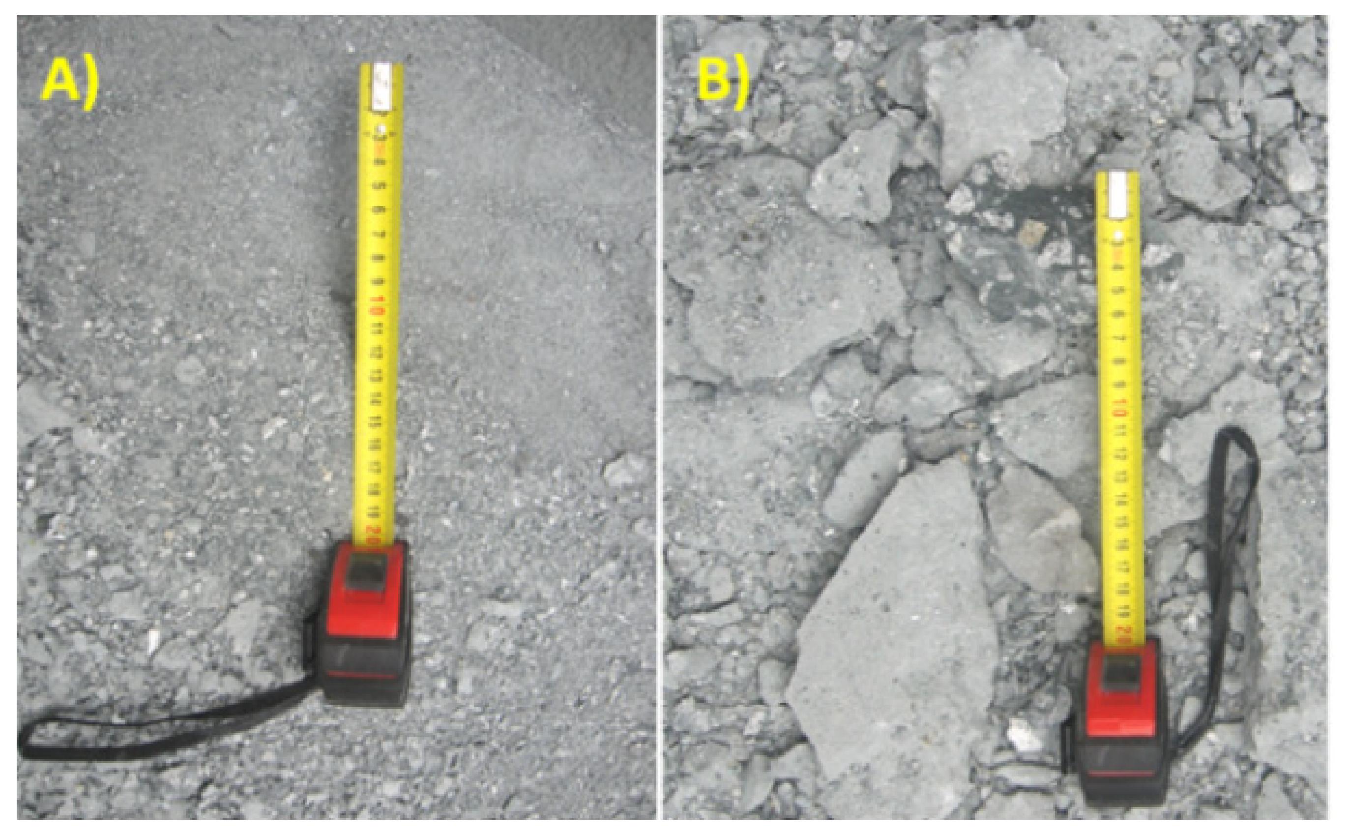
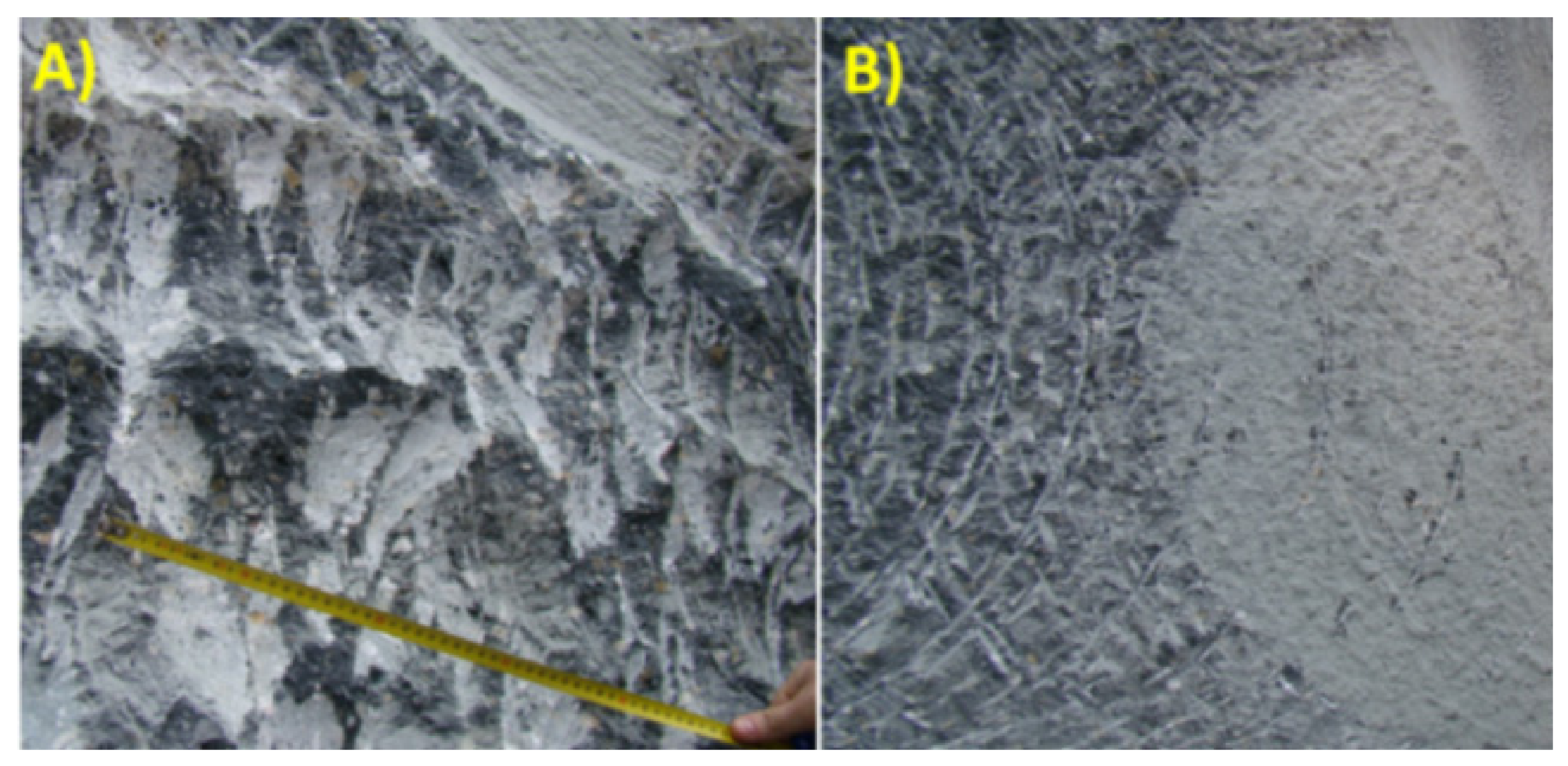
The best effects—a large grain size of output, low engine load, and reduced vibration—were achieved with the head body rotating counter-clockwise at 20 rpm, and with the plates rotating counter-clockwise at 60 rpm.
Figure 29 and
Figure 30 show the excavated output and the typical mined surface of the block for correct working conditions, compared to the results obtained with a standard mining head. No noteworthy wear signs of the disc tools were observed.
6. Summary and Discussion
The choice of the mechanical mining method depends largely on the excavated rock medium, its structure and strength parameters. For cutting tools, including in particular point-attack picks, the scope of application is limited to rocks with the uniaxial compressive strength of usually no more than 120 MPa, and with naturally weakened surfaces, containing no substantial inclusions of abrasive minerals. In the case of isotropic rocks or rocks with a substantial content of SiO₂, the use of cutting tools is not cost-effective due to their heavy wear. A number of auxiliary measures are taken to reduce this wear and the energy consumption involved in mining, while also ensuring that the process is as efficient as possible. These include water jetting, using new-generation materials for cemented carbide, or guard rings with wear-resistant weld overlay cladding.
These conclusions were confirmed by the results of laboratory and industrial tests performed in Department of Mining, Dressing and Transport Machines in AGH University of Science and Technology [
40,
41]. Rotary-tangential picks protected by additional safeguards or equipped with the new generation sintered carbide inserts were even several times more durable. However, it is connected with additional costs for manufacturing of these high-quality elements.
These solutions, however, do not always prevent the most challenging problem of tangential-rotary picks stopping their rotation and undergoing catastrophic wear. Results of tests presented in [
11,
29,
42] clearly show that even a small turnover of the tool in the holders allows its regular wear and significantly increases working time.
Symmetrical disc tools are the optimum solution for excavating compact and highly compact rocks without any naturally weakened surfaces. However, the large pressure forces exerted by these tools, as well as the size, weight, and costs of the TBMs on which these tools are mounted, restrict the application of this method to the driving of long galleries. Nevertheless, the very high daily advance rates, which can go as high as more than 70 m/day, set off the substantial energy demand and costs involved in the production and installation of the machine in the face.
Preliminary tests carried out by Department of Mining, Dressing and Transport Machines in AGH University of Science and Technology have also shown the possibility of using mini-disc tools for excavating such a compact rock as copper ore (in dolomites and anhydrites). However, this technique still requires improvement in the bearing construction of disc rotary tools [
43]. This is the reason for their rapid destruction.
Another interesting solution is the undercutting method. By taking advantage of the inferior shear strength of the rock to break it, this method reduces energy consumption while providing per-tool efficiency that is several times greater than that of disc mining tools which work by applying static crumpling to crush the rock. Utilizing their advanced design, the Aker Wirth miners can excavate galleries in compact rock with lower energy consumption and large grain size of output.
The same results were obtained in Department of Mining, Dressing and Transport Machines in AGH University of Science and Technology during the tests presented in [
39]. Only the problem with the durability of disc tools must be resolved.
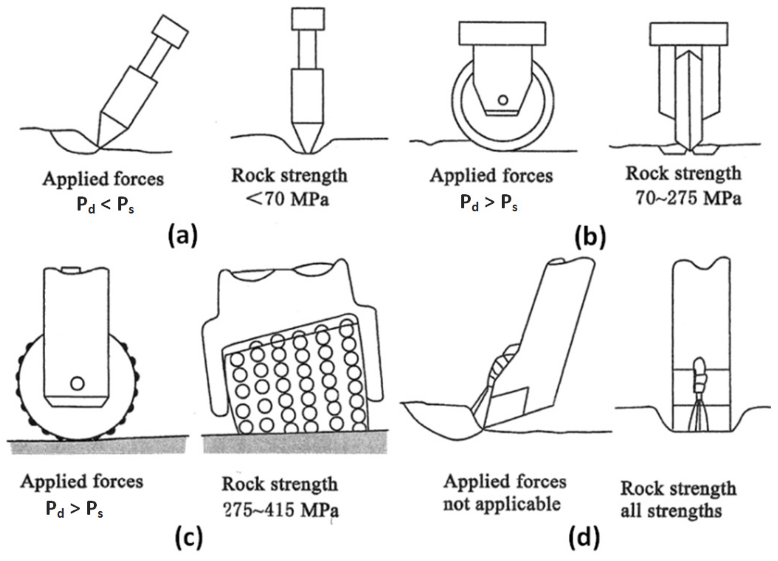
Similar conclusions on the application of various mining tools are presented in [
15] (
Figure 31). In this paper authors also propose a solution which involves supporting the radial-pick cutting process with a high-pressure water jet. By cutting a fissure in the rock and cooling the tool, this method substantially reduces the loads to which the machine is exposed, while also significantly extending pick service life. Creating a high-pressure water stream, however, requires the consumption of large amounts of energy. In some cases, the energy demand of this solution exceeds that of the conventional mechanical mining.
One of the relevant and as yet unsolved problems is how to clearly assess the workability of a rock medium [
44]. In qualitative terms there is general agreement between researchers that, as already mentioned, workability depends on compressive strength, tensile strength, shear strength, bedding, as well as the presence of weakened surfaces and hard minerals (above six on the Mohs scale). However, a universal qualitative method to assess workability has yet to be developed.
Summing up, before the choosing of heading’s driving method, first of all the rock geomechanical properties should be tested. Then the heading’s length, shape, and cross-section should be considered, together with the support type and the time in which the working should be completed. The final selection of the mechanical mining method is going to depend upon the financial possibilities.


