1. Introduction
Wireless power transfer (WPT) technology involves the use of electromagnetic waves to transmit electrical power through space [
1]. The application of this technology to the charging of electric vehicles (EVs) provides a viable alternative to the charging of EVs using cable connection between the EV and the electric grid [
2,
3]. The wireless mode of charging the EV offers the advantage of eliminating the hazards of open contacts and hanging cables while providing galvanic isolation and at the same time providing safe, automatic and reliable charging of EVs [
4]. WPT technologies can be classified into three main groups: electromagnetic radiation based, inductive coupling-based and magnetic resonant coupling-based WPT [
5,
6,
7]. Other nomenclatures to describe the three WPT technologies are used in other works. Electromagnetic radiation-based WPT is also denoted as microwave power transfer, inductive coupling-based WPT is often denoted as uncompensated inductive power transfer, and magnetic resonant coupling-based WPT is denoted as compensated inductive coupled power transfer [
8,
9].
For the commercial deployment of WPT, the major areas available for improvement are transmission distance, transmission efficiency and transmitted power level. Four major factors significantly affect the optimal design and technological drive towards achieving high transmission distance, efficiency, and power. These factors are coil configuration design, coil alignment, circuit design and environmental factors. The coil design and alignment both have a significant impact on the optimal design performance of WPT technology applicable for EVs. A practical resonant coil design involves the selection of an appropriate ferrite core, optimal geometrical design of ferrite core, optimal design of coil winding [
5] and selection of effective shielding topology.
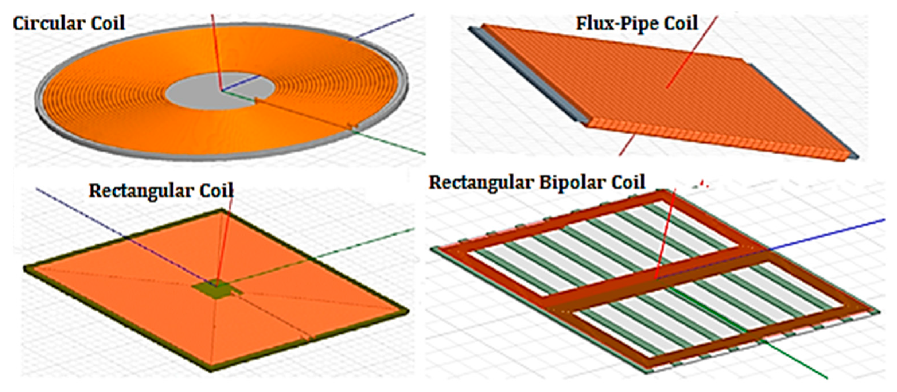
According to the research work presented by X. Mou and H. Sun [
5], it was noted that coil geometry significantly impacts the level of transmission efficiency. Flat circular coils, rectangular coils, bipolar coils and spiral coils have been reported to have effects on the electrical power transferred and transmission efficiencies [
10,
11]. Some common coil geometries are illustrated in
Figure 1. It was also noted by Li, Y. et al. [
12] that about 20% improvement in transmission efficiency can be achieved by using a high quality-planar litz coil. However, Z. Pantic and S. Lukic [
13] adopted two multi-layer multi-turn tube-like coils to improve transmission efficiency by considering the impact of skin effect.
It has been reported that the circular and rectangular coil models are capable of transferring a high amount of power while operating at high efficiency, typically over 90%. However, despite having the capability to transfer high power, they have a poor tolerance to misalignment as their individual power transfer efficiency (PTE) decreases significantly with horizontal misalignment of more than one-third of the individual coil’s diameter [
14]. In fact, it was noted that a horizontal misalignment of about half of the coil diameter will lead to zero magnetic coupling between the transmitter and the receiver [
15]. Due to the poor misalignment performance of the circular and rectangular coil topology, extensive research was carried out on the feasibility of the flux-pipe resonant coil topology. The flux-pipe resonant coil is designed by winding a coil of copper wire around a wide ferrite bar as shown in
Figure 1. In this design, the fundamental flux path is reduced to about 50% of the coil length thereby reducing the overall size of the resonant coil in addition to having better longitudinal and lateral misalignment tolerance [
16].
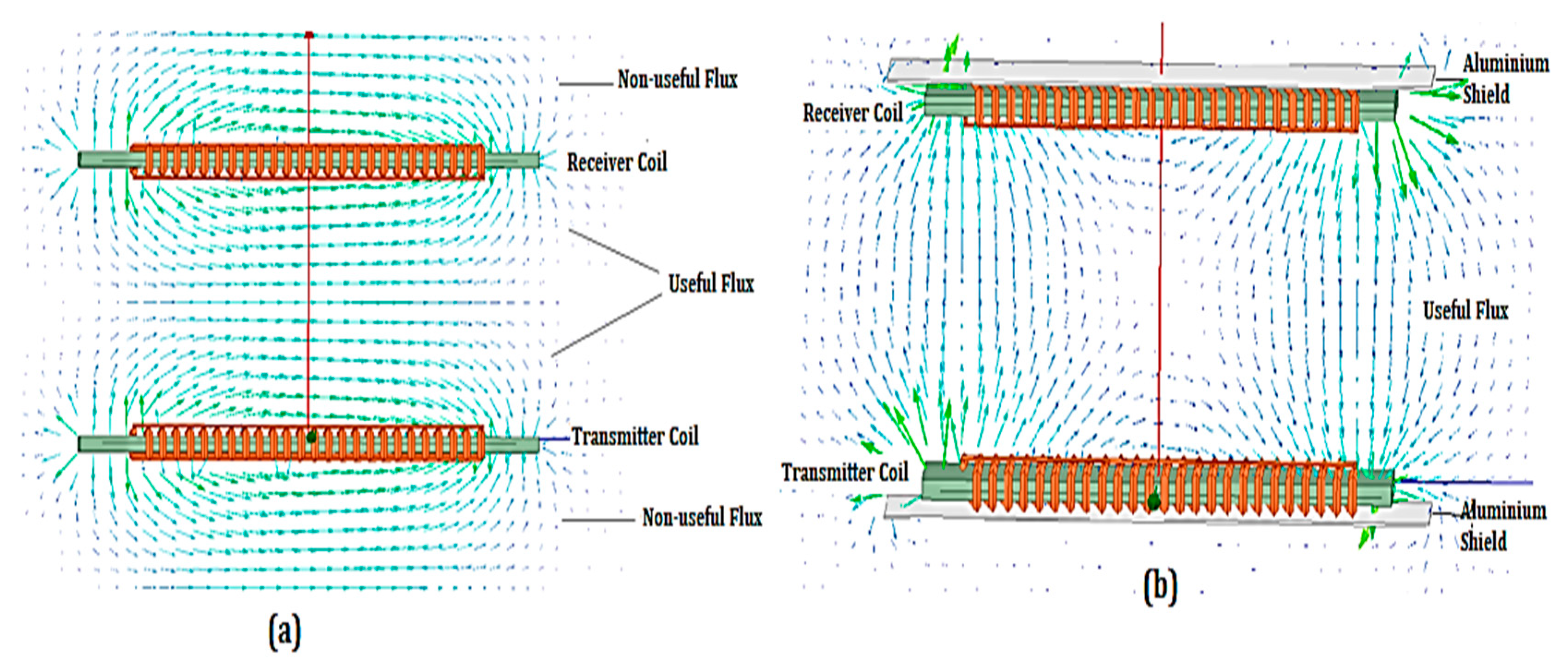
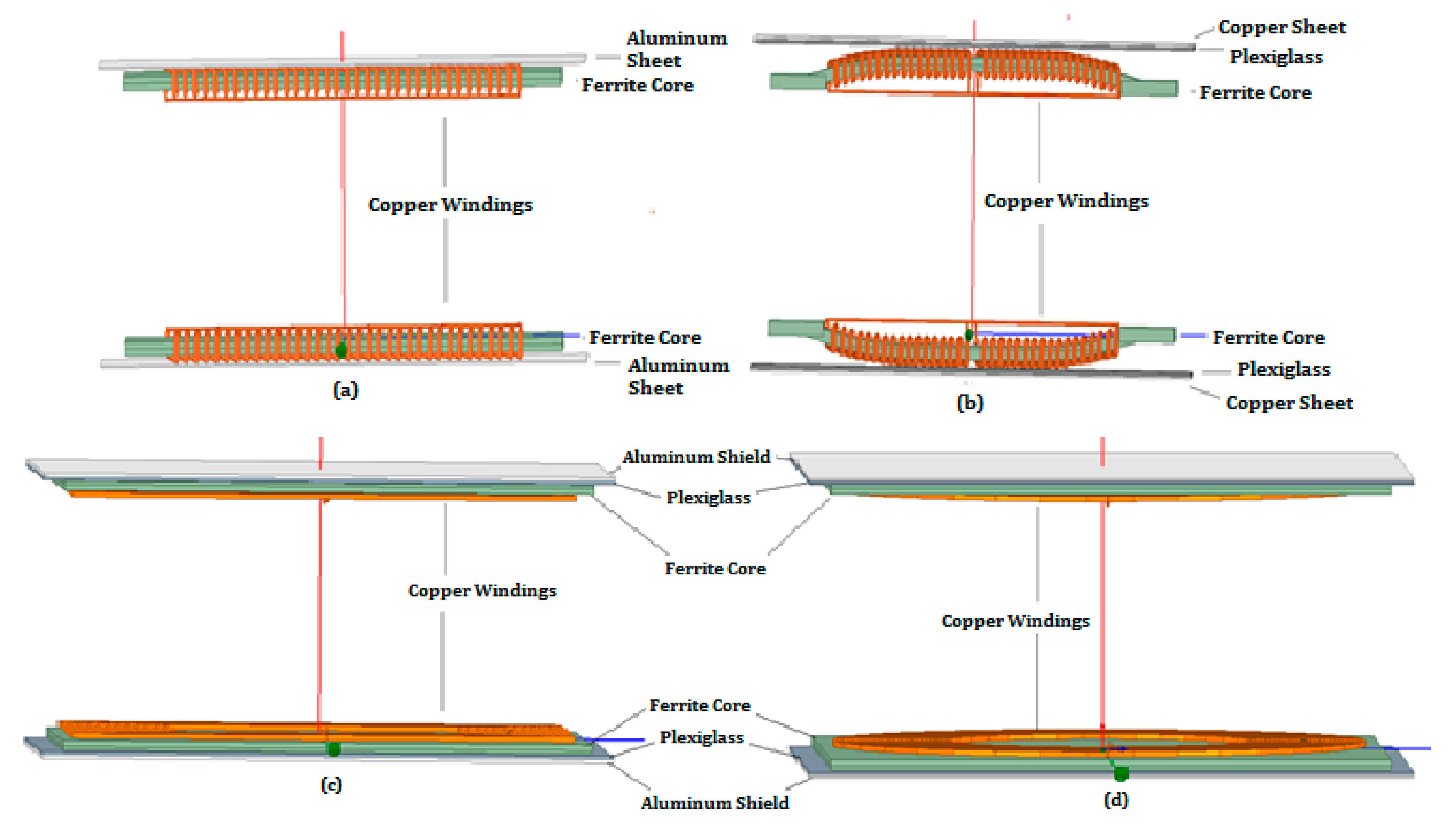
Despite the advantages of the flux-pipe resonant topology, there is a significant drawback limiting the amount of power it can transfer across an airgap. This limitation was due to the presence of “double-sided flux (DSF) path”, as shown in
Figure 2a. For a single flux-pipe resonant coil design, there are equal amounts of useful and “non-useful” flux produced at the upper and lower sides of both the transmitter and receiver coil. While the useful flux at the top side of the transmitter coil couples with the proportion of useful flux generated in the receiver coil, the “non-useful” flux is dissipated as eddy currents in the aluminum shielding installed at the back of the coils. This is illustrated in
Figure 2b. The resultant eddy current losses in the shields significantly reduce the efficiency and power delivered across the airgap to the receiver coils [
16].
Because of the double-sided flux problem, a significant amount of the total flux ends up as eddy current losses; only a very small percentage of the total power input can be delivered across the airgap with practical flux-pipe resonant coils designed for high efficiency. This was evident from the experimental results reported by [
17]. They developed a flux-pipe resonant coil model that was able to transmit up to 1.5 kW of power over a 7.5-cm airgap at an overall efficiency of 95%. Likewise, according to the experimental results of Takanashi et al. [
18], a flux-pipe resonant coil model was developed with a capability of transmitting 3 kW across a 20 cm airgap at an overall efficiency of 90%.
To maintain the optimal performance of the circular and rectangular resonant coil topology over a wider range of lateral and longitudinal misalignment, and at the same time have a high coupling strength close to the flux-pipe resonant coil topology, T.D. Nguyen et al. [
16] developed a rectangular bipolar type resonant coil design consisting of two rectangular coils placed side by side over a series of ferrite bars, as shown in
Figure 1. In order for their model to achieve better performance and a significant increase in the fundamental flux height, a rectangular bipolar coil with an effective area of 0.48 m
2 was proposed. From the experimental results obtained, the model developed was able to transmit up to a maximum of 8 kW over a 20 cm airgap at a D.C.-to-D.C. efficiency of 95.66% when both the primary and secondary coils are perfectly aligned. The proposed model was also able to transfer an electrical power of 4 kW across the airgap when the lateral misalignment is set at one-third of the coil’s length with a D.C.-to-D.C. efficiency of 95.39%. Despite the performance improvement of the rectangular bipolar coil over the conventional circular, rectangular and flux-pipe resonant coils, the design model has a significantly higher weight and size when compared to the power output and efficiency obtained. In addition, there is a significant decrease in power output across the airgap with an increase in lateral misalignment.
Thus, in this paper, a further investigation and modification of the geometric and shielding parameters responsible for the poor performance of the traditional flux-pipe resonant coils were performed. This was achieved by mathematical analyses of the various loss equations to ascertain the key parameters responsible for the various losses. A geometric and material modification of the traditional model was undertaken to achieve an optimal model, which minimized the various losses encountered with the traditional model. Finally, equivalent circular model, rectangular model, and traditional flux-pipe model designs together with the optimized model design were subjected to finite element analyses and the results presented and compared to ascertain the level of loss reductions, increase in power output and improvement in efficiency values in the proposed optimal design model.
2. Optimal Finite Element Modeling of Flux-Pipe Resonant Coil Topology
This section presents an ANSYS
® Maxwell 3D finite element modeling and design of the circular model, rectangular model and the proposed optimal flux-pipe resonant coil design. For modeling design and analysis proposed in this research work, appropriate initial and boundary conditions were selected, model designs from the authors of [
4,
19] were replicated and simulated, and the results obtained were compared against their experimental results. The resulting comparisons were accurate to within ±6% error, which was deemed to be within an acceptable tolerance for all the research models replicated.
To provide a fair and accurate comparison of the performance of the proposed flux-pipe model with the circular and rectangular models, each of the coil models was modeled using the same length and thickness of litz wire, volume of ferrite core and thickness of shield material. Litz wire was used in the model designs because it is not affected by skin and proximity effect at frequencies lower than 360 kHz [
20]. As a result, litz wire is used by most researchers and engineers for the windings of wireless power systems [
12,
20,
21,
22]. The length and thickness (cross-sectional diameter) of the litz wire were optimally chosen to be 15.4 m and 6 mm, respectively. Similarly, the volume of the ferrite core and thickness of the shield material used are 1.272 m
3 and 1.5 mm, respectively. Each individual dimension of the coil models is shown in
Table 1.
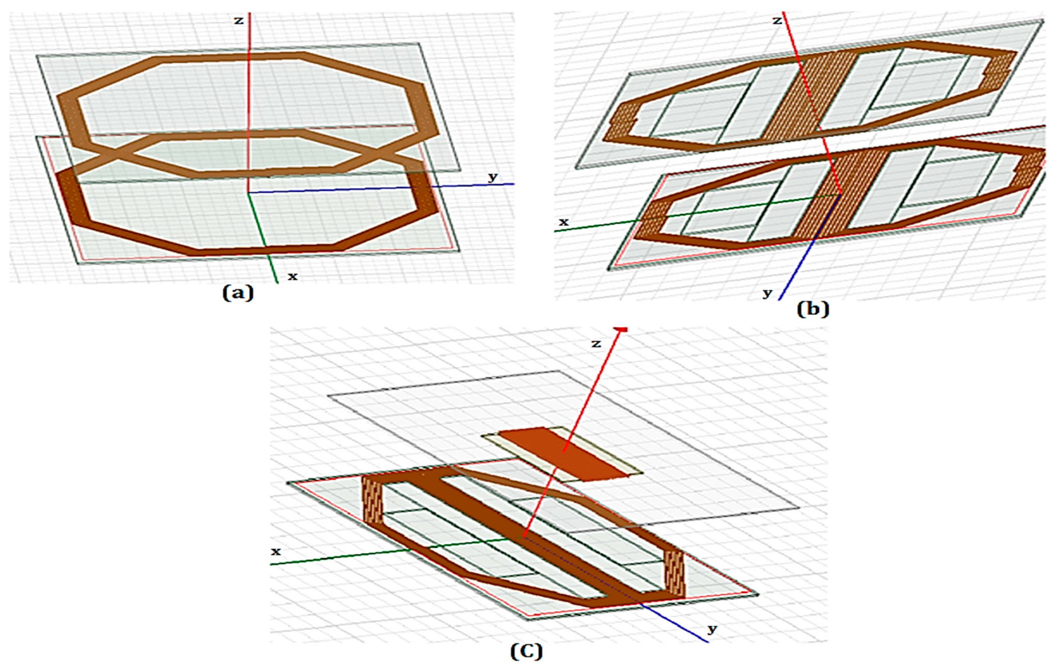
Based on the parameter specification of each of the resonant coil models shown in
Table 1, appropriate designs for each model was built in the Ansys Electronic Desktop environment, as illustrated in
Figure 3. The specification of coil turns for the flux-pipe model was based on the works of B. Olukotun et al. [
23]. It was noted that increasing the number of coil turns of flux-pipe resonant coil using a fixed length of litz wire increases the level of magnetic coupling.
3. Parameter and Design Optimization of Flux-Pipe Resonant Coil Topology
As discussed in the literature, the major setback responsible for the low adoption of the flux-pipe resonant coil topology for use in WPT application is the magnitude of “non-useful” flux, which is equal to the amount of useful flux in the system. The “non-useful” flux is responsible for the majority of the eddy current losses on the aluminum shield plates. There are also the additional ohmic losses of the copper coil and the core loss in the ferrite core used in boosting the magnetic flux of the flux-pipe coil topology.
The ohmic losses (W) in the coil windings is given mathematically by [
24,
25]:
where I(A) is the current in the coil windings and
is the equivalent A.C. resistance of the coil windings consisting of direct current (DC) resistance and resistance due to the skin and proximity effect [
24]. An optimal design must aim to reduce either the current or the total A.C. resistance of the coil or both.
Likewise, the power loss (W) in the ferrite core can be expressed as [
26]:
where
, α and
are constants which are dependent on the grade and properties of the core used. For the FDK 6H40 ferrite core used for this research, the values of the constants are
= 2.0312,
α = 1.418, and
β = 2.755 [
26].
f (
) is the resonant frequency and
is the maximum magnetic flux density in the core. An optimal design with low core losses will require a design that reduces the amount of magnetic flux density as well as the resonant frequency.
According to P. P. Parthasaradhy and S. V Ranganayakulu [
27], the power loss per unit mass of a thin sheet due to eddy current under certain conditions of uniform material and magnetic field with no skin and proximity effect is given by;
where
is the power loss per unit mass (
), d is the thickness of the shielding sheet (
),
is the resistivity of the material (
) and
is the density of the material (kg/m
3). From Equation (3), it can be noted that using a conductive material with higher resistivity and density reduces the amount of eddy current per unit mass in the shielding plate. In addition, an increase in the magnetic flux, sheet thickness and resonant frequency increases the eddy current losses.
To maintain a very high power transfer efficiency (PTE) of the coil, another important factor, known as the quality factor (
), must be optimized; it is given mathematically as [
5]:
where
is the resonant frequency of the resonator circuit,
R (Ω) is the coil intrinsic resistance and
is the self-inductance of the resonant coil. The quality factor indicates the ratio of the inductive properties of the coil to its resistive properties. A higher value of
Q indicates a greater ratio of the inductances to the electrical resistance of the coils creating lower electrical power losses in the coils. The quality factor can be enhanced by increasing the resonant frequency but this leads to higher losses in the power electronic components. Alternatively, increasing the self-inductance of the coil may likely increase the intrinsic resistance of the coil; thus, there is a trade-off to ensure that the intrinsic resistance of the coil is as low as possible.
For typical flux-pipe resonant coils, there are three areas of optimization—the coil winding, the ferrite core geometry and the selection of appropriate shield material based on Equations (1)–(3)—to achieve stronger coupled, lower loss, higher power and higher PTE of the resonant coils.
3.1. Coil Winding Optimization
For most designs of flux-pipe resonant coil topology, the traditional approach is to wind single copper wire around a magnetic ferrite core, as illustrated in
Figure 1 and
Figure 3.
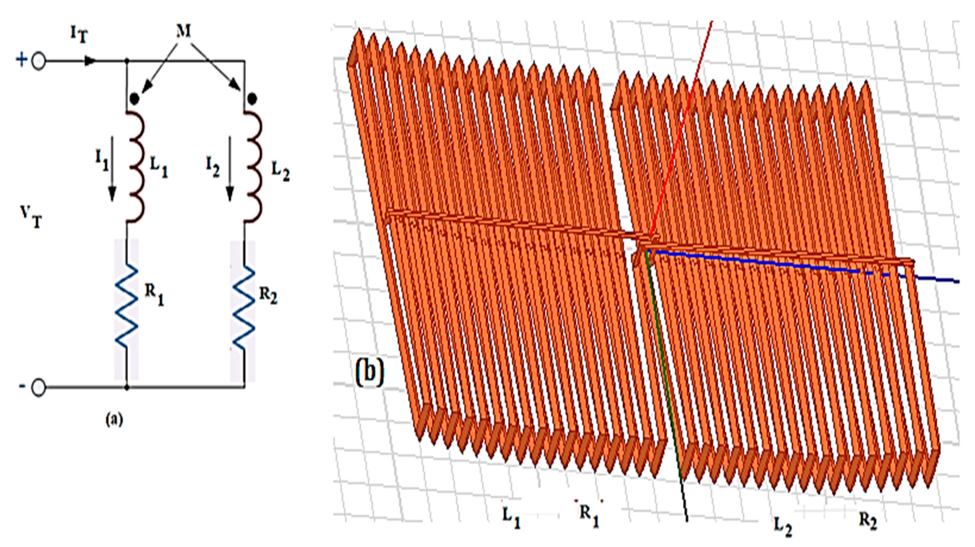
An optimal design alternative proposed in this paper is implemented by dividing the single copper wire into two and creating two copper winding coils on the same ferrite core at very close proximity to each other; the two windings are electrically parallel to each other but mutually coupled magnetically to aid the maximum flux linkage between the primary coil and secondary coil. The circuit, as well as the finite element modeling design implementation, is illustrated in
Figure 4 [
28]. The design implementation is a slight variation of the model implemented by M. Budhia et al. [
29].
The traditional flux-pipe model design representation in
Figure 2 with 34 turns was split to create two windings of 17 turns each, as shown in
Figure 4b. The two coils are electrically parallel to each other but mutually coupled magnetically. The total current is divided between the two coil windings while maintaining the same voltage across them. The total Inductance (
) of the two parallel aiding resonant coils is given as [
28]:
Since the two windings have similar sizes and configuration,
and Equation (5) is reduced to the form:
Likewise, the total resistance of the two parallel resonant coils is given by:
From Equations (5)–(7), it was noted that the total resistance of the traditional winding coil is reduced by a factor of four ( The total self-inductance of the coil is reduced by a factor of less than three when compared with the traditional flux-pipe model. This will invariably increase the quality factor of the coil. Since the total current in the coil windings is reduced by one half due to the two coils being connected in parallel, this will bring about a significant reduction in the ohmic losses as well as the eddy current and core losses. From Equations (2) and (3), the maximum magnetic flux density in the core and windings is correlated directly to both the core loss and eddy current losses.
Similarly, Takanashi H et al. [
18] developed and proposed an equation relating the maximum efficiency to the quality factor and the coupling coefficient and it is given by:
where
is the product of the primary quality factor
and the secondary factor
. Equation (8) is very useful in determining the optimum resonant frequency to attain maximum efficiency.
3.2. Ferrite Core Modification
In the traditional flux-pipe design topology with a uniform ferrite core, the amount of useful and “non-useful” flux is theoretically the same. While the useful flux is mutually coupled with the secondary coil and responsible for efficient power transfer, the “non-useful” flux is responsible for the majority of the eddy current losses in the conductive aluminum sheet used for shielding humans and the chassis of the car from the electromagnetic fields. Theoretically speaking, half of the core thickness is responsible for both the propagation of the useful magnetic flux and the other half for the propagation of the “non-useful” magnetic flux.
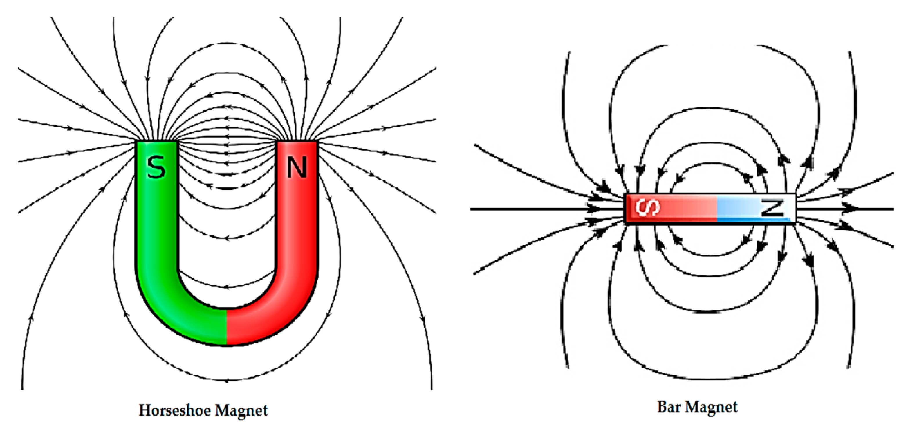
An optimal approach is to modify the ferrite core geometry in such a way as to align the greater volume of the ferrite core to support the production of useful flux. This is achieved by slightly bending the ferrite core in
Figure 5a into a C-shape similar to the horseshoe magnet as well as extending the ferrite bar protruding at the edges of the copper winding by a significant amount; thus, more than 60% of the ferrite core volume is oriented to support the creation of the useful magnetic flux. This is illustrated in
Figure 5b. The curved section of the ferrite core is a section of a circular arc of radius 0.9 m at an angle of 25°. The reasoning behind the core modification is based on the difference in the magnetic field between a bar magnet and a horseshoe magnet, as illustrated in
Figure 6.
From the flux distribution shown in
Figure 6, it is clear that the total magnetic flux is more concentrated at the poles of the horseshoe magnet while it is evenly distributed in the case of the bar magnet. The curved portion of the horseshoe magnet has the least leakage flux. Applying the same logic to the proposed core design, the curved portion of the ferrite core has the least flux leakage, thus the fluxes responsible for eddy current distribution are reduced.
The magnetic flux distribution around the core illustrated above is similar to that of the curved trapezoidal magnetic flux concentrator designed in [
30]. In the research work of K. Zhu and P.W.T. Pong [
29], the sensitivity of a magnetic sensor was improved by creating structures composed of several curved bar-shaped magnetic flux concentrator sandwiches. Using a similar approach, our proposed optimal design model ensures that there is reduced flux leakage around the curved areas of the ferrite core and are more concentrated on the protruding edges, which significantly reduces the amount of magnetic flux leakage incident on the shield sheets; this, in turn, reduces the eddy current losses in the shield sheets. The finite element model implementation of the circular, rectangular, traditional, and optimized flux-pipe models is illustrated in
Figure 7.
3.3. Selection of Shielding Material
In the traditional flux-pipe model topology as well as other resonant coil topologies, aluminum metal sheet is usually used for the shielding of electromagnetic flux [
4,
11,
26]. On this aspect, there was a need to proffer another alternative to aluminum as a shield based on Equation (3). An affordable alternative was to use a copper sheet as the electromagnetic shield. From Equation (3), under a constant maximum flux density, resonant frequency and shield thickness, an increase in the resistivity and density of the shielding sheet will result in a reduction in the eddy current power loss per unit mass.
The resistivity of aluminum is
, which is higher than the resistivity of copper, i.e.,
, by a factor of 1.54. The density of copper is
, which is higher than the density of aluminum, i.e.
, by a factor of 3.30. Thus, the eddy current power loss per unit mass of aluminum is more than twice the loss per unit mass with copper and thus a copper shield of 2 mm thickness was chosen as the thickness is commonly used with many research model designs. In addition to the shielding, plexiglass with a thickness of 3 mm was placed between the copper windings and the copper shield to act as support as well as ensure a rigid structure for the overall resonant coil topology. The choice of this material is based on its lightweight and thermal tolerance. The overall finite element model of the optimal resonant coil design is presented in
Figure 7b.
3.4. Circuit Design
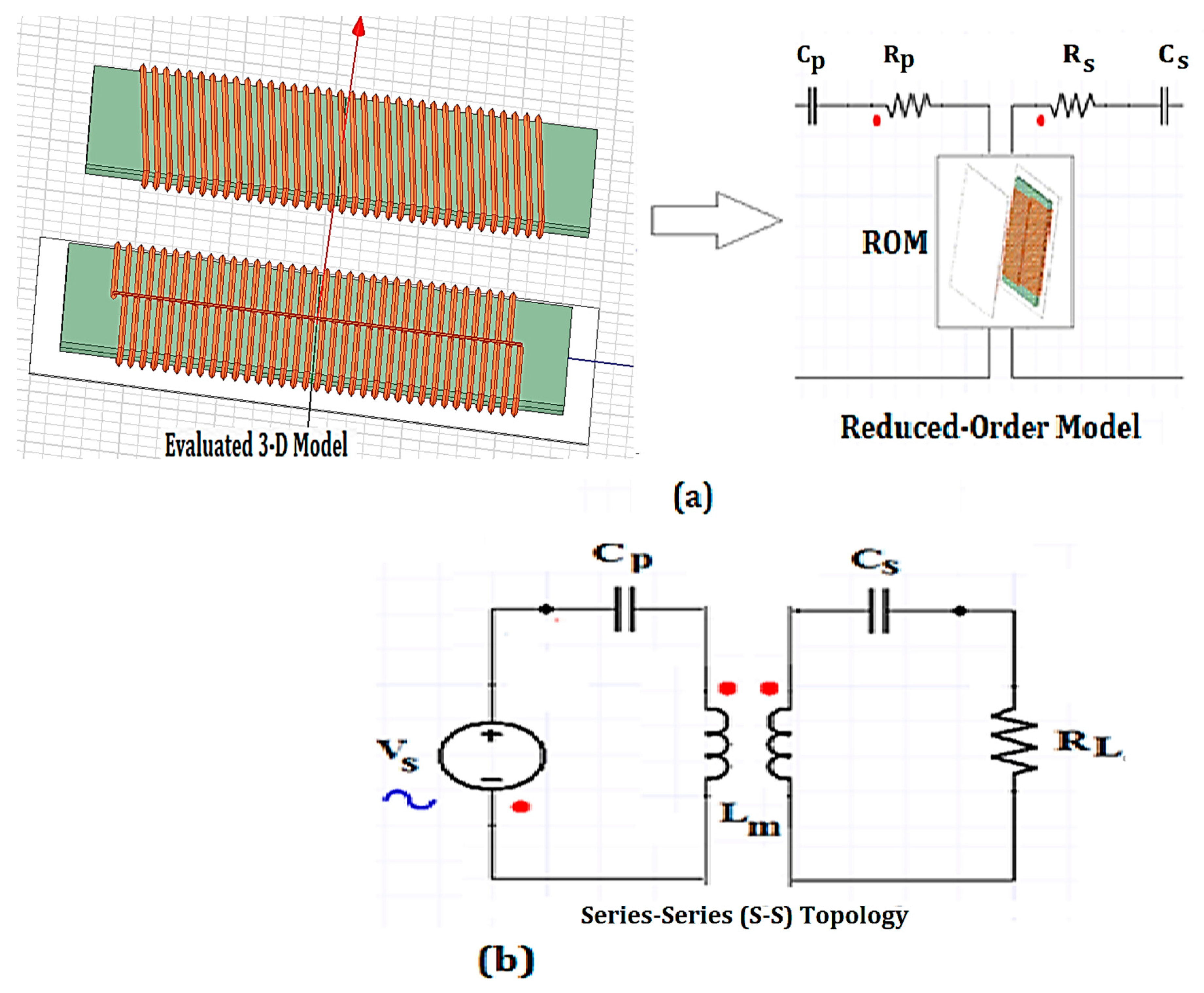
The circuit analysis was undertaken by importing the reduced-order 3D model into Simplorer® (version 17.1, Ansys, Canonsburg, PA, USA) circuit environment and an alternating current (AC). analysis was undertaken to determine the power level as well as the coil-to-coil efficiency of the model designs. Due to the presence of an airgap between two resonant coils, there is an increase in the magnetizing current and leakage inductance. Thus, to compensate for the leakage inductance as well as to strengthen the coupling between the coils, a compensating capacitor was connected to the primary and secondary coils. The capacitors can be arranged in four basic configurations: series–series (SS), series–parallel (SP), parallel–series (PS) and parallel–parallel (PP). According to Kalwar et al. [
8], the SS configuration can transfer high power with very high efficiency. Similarly, implementation of wireless power transfer system using the SS configuration with overall efficiency of more than 92% has been reported [
31,
32,
33,
34]. The reduced-order model implementation and SS compensation configuration are illustrated in
Figure 8.
For an accurate generation of results from the circuit simulation, the appropriate parameters of source voltages , intrinsic resistances and the appropriate capacitance for resonance are specified.
,, and are the intrinsic resistance of the primary coil, intrinsic resistance of the secondary coil and the load resistance, respectively. The values of and are normally evaluated through eddy current analysis and need to be manually inputted before the circuit simulation to avoid runtime errors.
and are the primary compensation capacitance and secondary compensation capacitance, respectively. They are evaluated as a function of the self-inductance of the primary coil and self-inductance of the secondary coil .
The primary capacitance and secondary capacitance in the circuit are given mathematically as:
is the resonant angular frequency of the WPT system model measured in rad/s and mathematically represented as where is the resonant frequency measured in Hertz (Hz). The term is the leakage factor.
4. Finite Element Analysis and Simulation Results
The finite element analysis is divided into three aspects: the magnetostatic, eddy current and electric circuit analyses. The magnetostatic analysis deals with the maximum magnetic flux saturation limit of the core as well as the coupling factor performance with variation of the airgap, lateral and longitudinal misalignment. The eddy current analysis gives the performance evaluation of each of the four model designs (presented in
Figure 7) with respect to the three major losses: the ohmic, core and eddy current losses. Similarly, the circuit analysis indicates the performance of each of the four model designs (circular model, rectangular model, traditional flux-pipe, and optimized flux-pipe models) in terms of the quality factor, power level, current level, and coil-to-coil efficiency.
4.1. Validation of Model Design
To create finite element models with performance characteristics close to the experimental models, optimal initial conditions, boundary conditions and distance between adjacent coil turns were selected using an iterative approach. The model design validation prototypes were implemented by modeling three experimental models created by Lempidis, G. et al. [
4] based on published physical size and material parameters of each experimental model. The recreated finite element models are illustrated in
Figure 9.
To design an accurate 3D representation of the proposed models as well as accurate result analysis, a boundary region offset of 40% was chosen. The distance between adjacent coil turns was chosen to be twice the cross-sectional diameter of the chosen litz wire. Based on the specified design specifications and conditions, magnetostatic analysis of the three model designs was undertaken. The experimental and simulation results are presented in
Table 2.
Cases A–C models correspond to the illustrated models shown in
Figure 9. From the results presented in
Table 2, it is noted that a minimum accuracy of 94% was obtained for all the simulation parameters analyzed. Thus, the design specifications and boundary conditions adopted from the model validation were chosen for the proposed model designs in this research with an expected accuracy of above 90% of the experimental results.
4.2. Validation of Coil Winding Specification
To validate the optimal choice of splitting the original coil windings of the traditional flux-pipe into two parallel half windings instead of three or more coil windings, the 34-turn coil windings were remodeled to create three and four copper windings. The three-copper winding consists of two windings with 11 turns each and a winding with 12 turns. The four-copper winding consists of two windings with eight turns each and another two windings with nine turns each. An initial finite element and circuit analysis was performed on each of the versions of the coil windings and the results are presented in
Table 3.
From the results presented in
Table 3, it is noted that the power losses, intrinsic resistance, self-inductance, and coupling inductance reduce with an increase in the number of split windings. Despite a significant reduction in power losses with an increase in the number of split windings, Cases III and IV have a significant reduction in coil-to-coil efficiency when compared with Case II. With respect to important parameters such as coupling coefficient,
and coil-to-coil efficiency, the choice of Case II is justified. Comparing the models in Cases I and II, it is noted that Case II has a reduction in total power losses by a factor of more than five. In addition, the intrinsic resistance of Case II is a quarter of the intrinsic resistance of Case I, which agrees with Equation (7). Thus, the simulation results agree with the theoretical analysis and the justify the choice of Case II.
4.3. Magnetostatic Analysis and Simulation Results
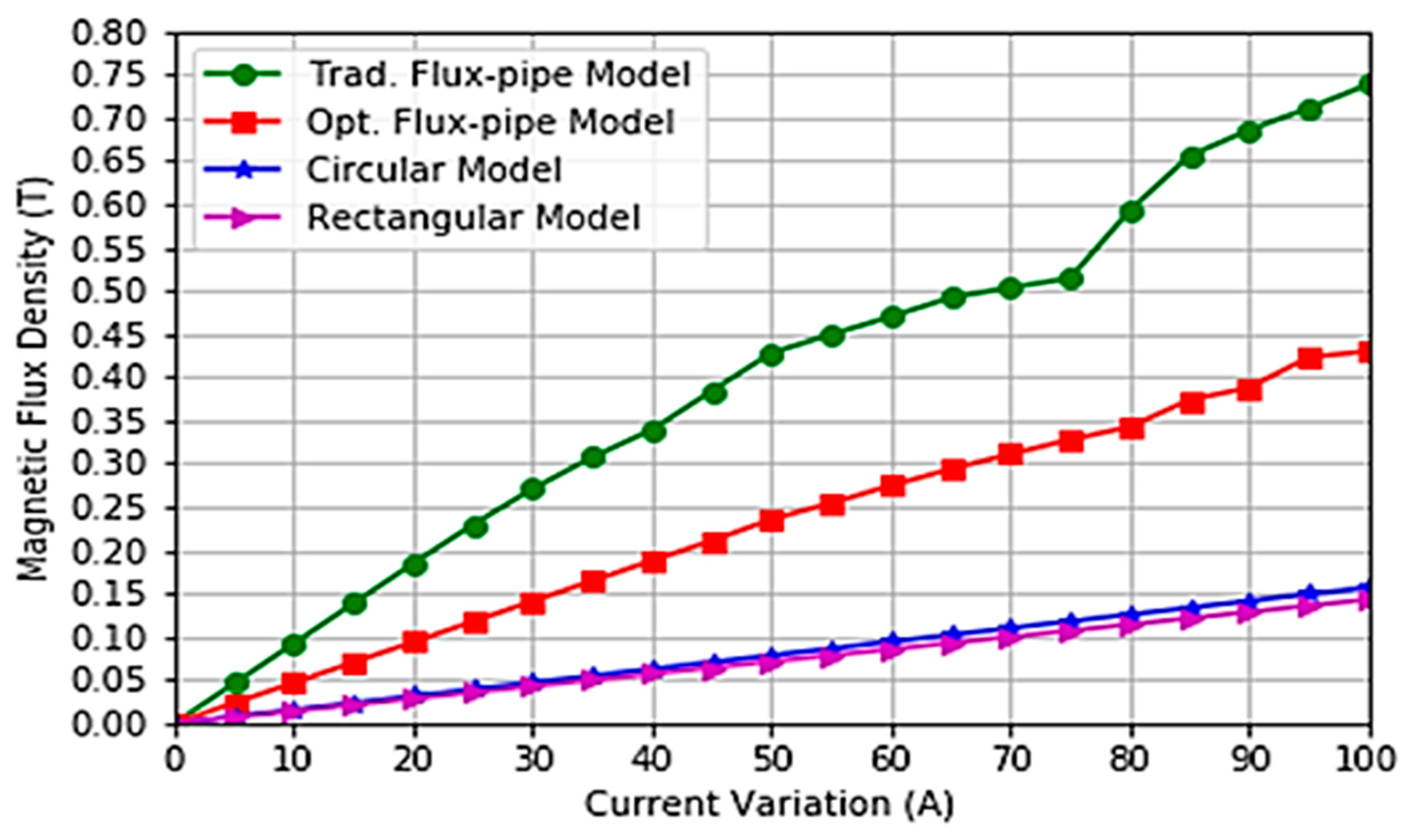
The first magnetostatic analysis involves running a parametric sweep of excitation currents from 0 A to 100 A and the corresponding values of the maximum magnetic flux density were calculated across an airgap of 200 mm for the circular model, rectangular model, Model 4, and Optimized Model 4 respectively, as illustrated in
Figure 7. The results are illustrated in
Figure 10. In addition, the flux density distribution across the primary and secondary cores of the circular, rectangular, traditional, and optimized flux-pipe model designs at an excitation current of 50 A are shown in
Figure 11.
From the results presented in
Figure 10, the optimized model design delivers a lower magnetic flux density distribution with respect to excitation current setting when compared with the traditional flux-pipe model. In addition, at an excitation current of 50 A, while the traditional flux-pipe model has a maximum flux density of 0.430 T, the optimized model has a maximum flux density of 0.212 T, which is more than a 50% reduction in the maximum flux density at that current. This will lead to a significant reduction in eddy current losses and core loss according to Equations (2) and (3).
4.4. Parametric Analyses of 3D Design Model
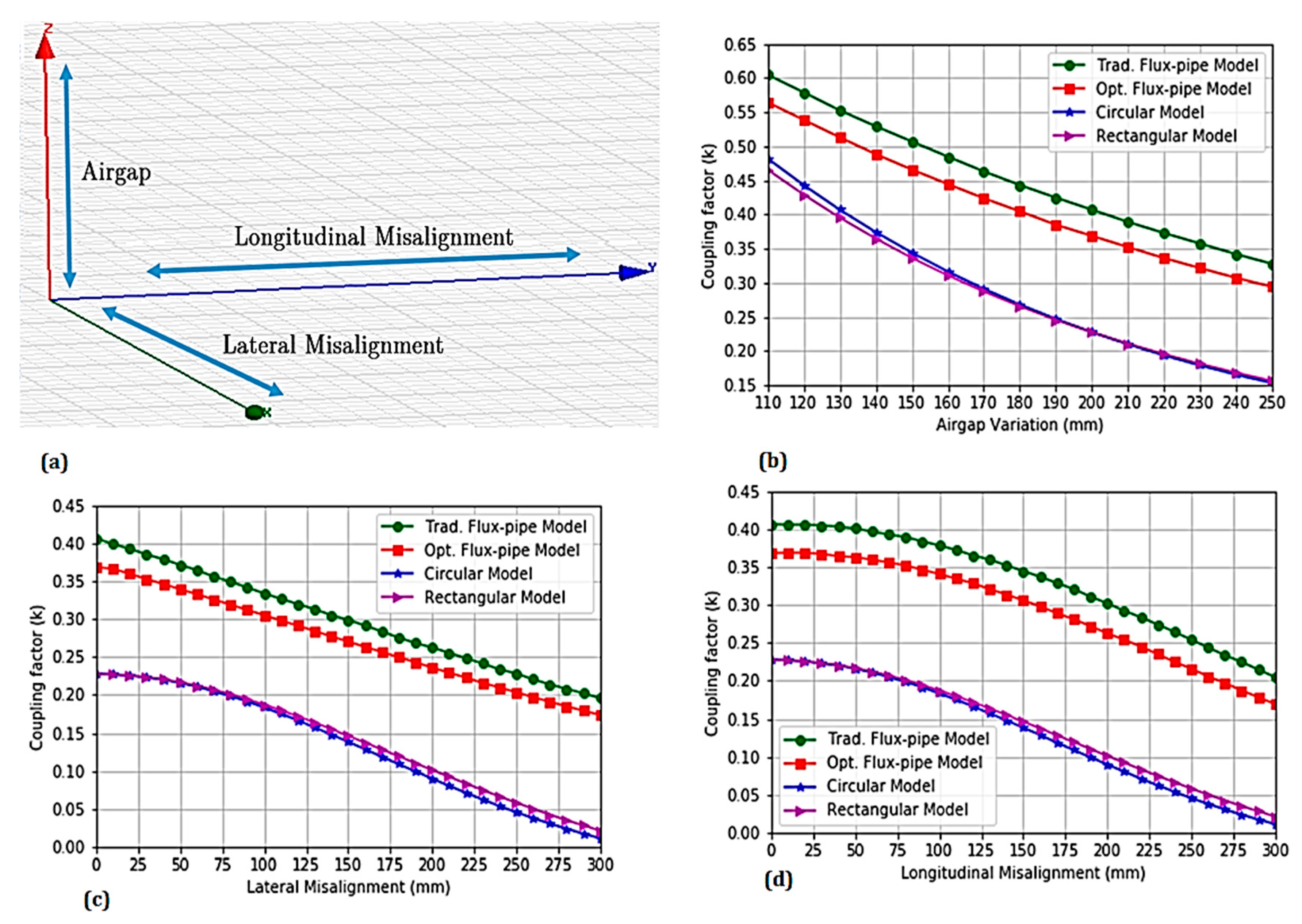
Likewise, a parametric sweep to evaluate the performance of each of the four model designs under airgap and misalignment variation is presented in
Figure 12. The airgap variation follows the SAEJ2954 limits of 250 mm [
35].
From the results presented in
Figure 12, it can be seen that the optimized flux-pipe model delivers a slight reduction in performance for all the airgap and misalignment settings with respect to the coupling factor. The trade-off in magnetic coupling resulted from the slight curvature of the ferrite cores of the primary and secondary coils as detailed in
Figure 7b. The curvatures in the ferrite cores increase the overall airgap slightly, thereby decreasing the value of the magnetic coupling coefficient. Similarly, the circular and rectangular model designs have significantly poor misalignment performance for all the misalignment settings. The results obtained agree with results from the literature.
4.5. Eddy Current Analysis
The eddy current analysis of the two model designs aims to show the magnitude of losses present in each coil model at the resonant frequency at a particular current excitation. The initial evaluation of the losses for each of the coil designs is undertaken by injecting an excitation current of 32 A in the coil windings at a resonant frequency of 85 kHz. The operating frequency of 85 kHz was chosen because it is the operating frequency proposed by SAE J2954 task force for interoperability of different WPT charging systems. The results of the analyses are presented in
Table 4.
For such medium power application, it is noted that there was a significant reduction of more than 83% in the total losses for the optimized flux-pipe model when compared with the traditional flux-pipe model.
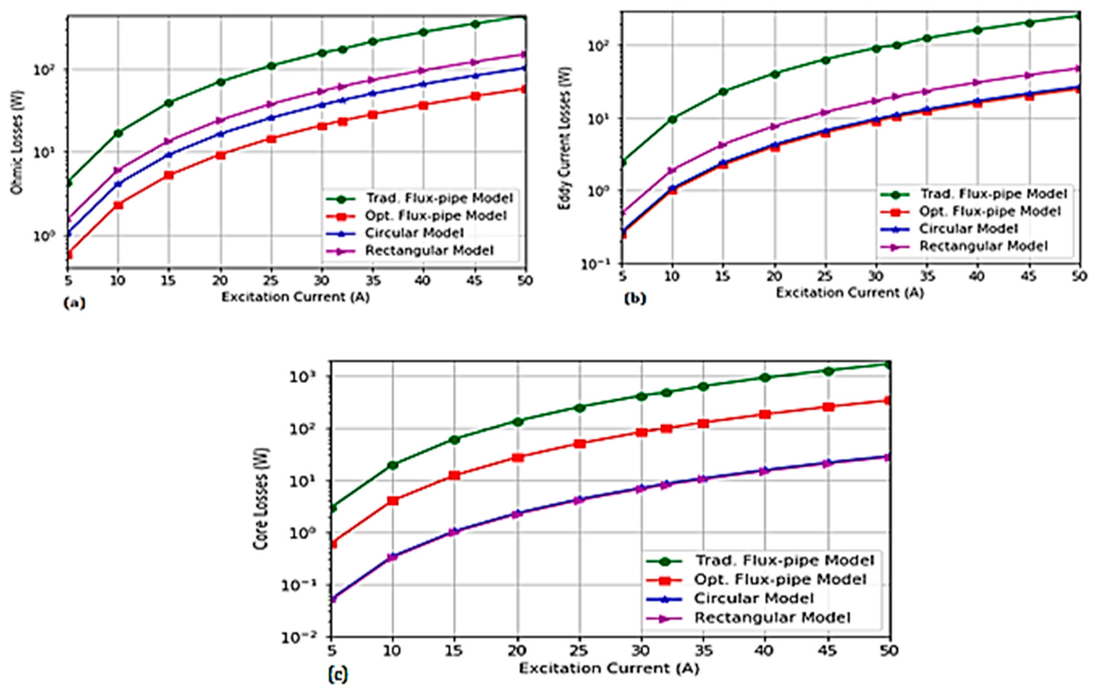
At constant excitation current of 32 A, a parametric sweep of operating frequencies from 5 kHz to 100 kHz was performed on the coils and the corresponding values of ohmic losses, core losses and eddy current losses were evaluated, as presented in
Figure 13. In addition, a parametric sweep of excitation current from 5 A to 100 A at the fixed resonant frequency of 85 kHz was undertaken. The corresponding values of the core losses and eddy current losses are presented in
Figure 14.
From the results presented in
Figure 13, it is noted that the ohmic losses and eddy current losses are relatively constant over the range of resonant frequencies at a particular current while the core losses increase with an increase in operating frequency. It is also observed that the optimized flux-pipe model has the lowest ohmic and eddy current losses over the range of frequencies. In addition, the core losses in the optimized flux-pipe model are lower than that of the traditional flux-pipe model.
Similarly, from the results presented in
Figure 14, the eddy current losses and core losses increase with an increase in the excitation current at a set resonant frequency. Consequently, there is a significant reduction in both the eddy current losses and core losses in Optimized Model 4 compared with the eddy current losses and core losses for the same settings of excitation current. The reduction in losses in the optimized model is as a result of a reduction in the maximum flux density as a result of physical modification of the coils and the ferrite core based on Equations (2) and (7). Thus, for each of the corresponding loss analyses, it was observed that the optimized flux-pipe model has the lowest amount of ohmic and eddy current losses. In addition, it has lower core losses when compared with the conventional flux-pipe model for each value of excitation current.
4.6. Circuit Analysis
In the circuit analysis, the performance of the coil designs in terms of coil-to-coil efficiency and power output were evaluated. The parameters required for accurate analysis were obtained from the eddy current analysis solution. The required parameters for the three model coils at an adaptive modeling frequency of 85 kHz are presented in
Table 5.
Based on the parameters obtained in
Table 5, the relationship between maximum efficiency
and the parameter
over a range of frequencies was evaluated using Equation (8) and the graph is presented in
Figure 15.
Based on the result presented in
Figure 15, it is noted that increases in resonant frequencies positively affect the maximum efficiency of the coil. Similarly, it is noted that the optimized flux-pipe model has the best efficiencies over the range of frequencies. Thus, theoretically, the proposed model design is justified.
4.7. Impact of Load Resistance On the Performance of Coil Designs
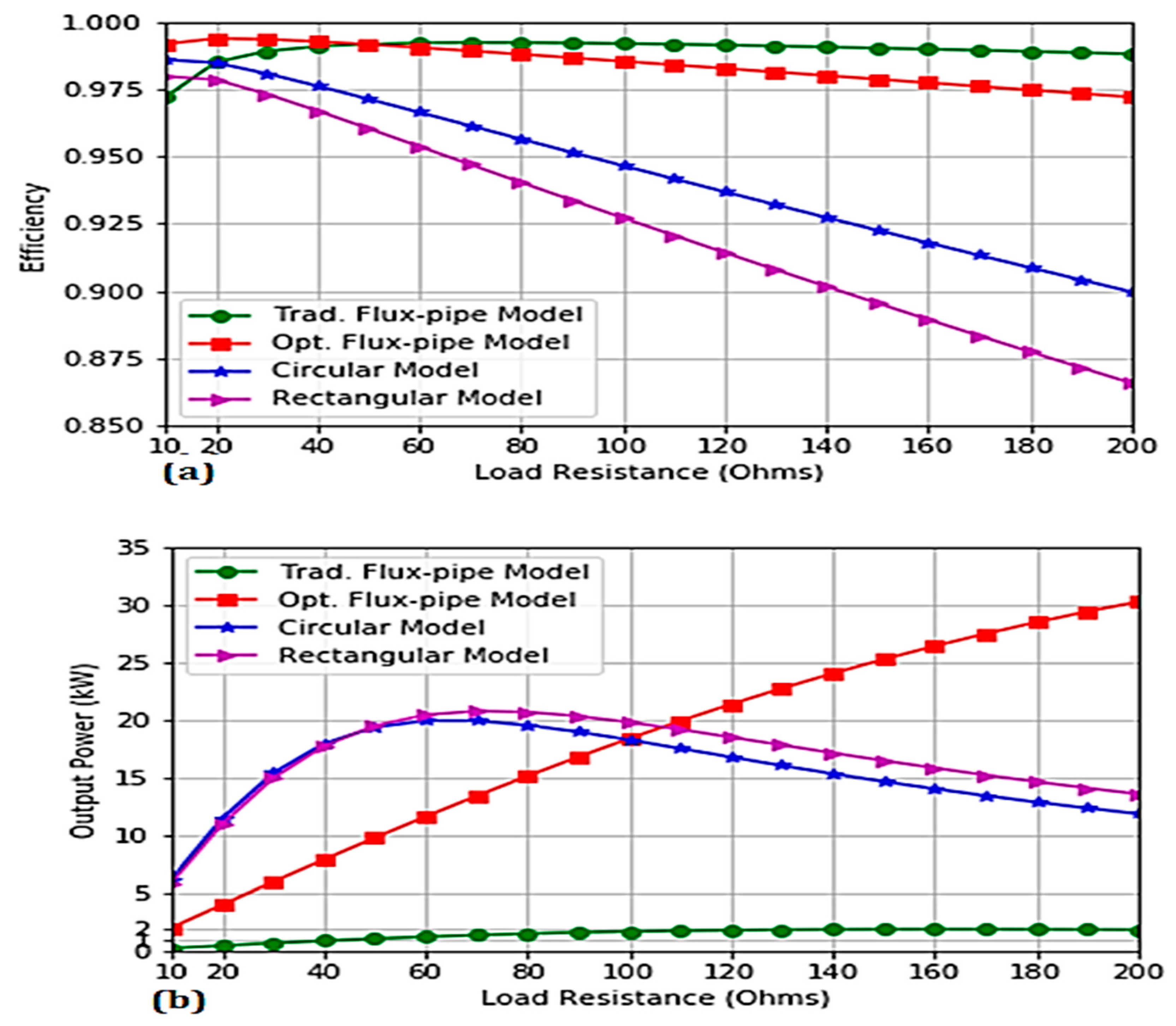
To determine the impact of load resistance on the power transfer efficiency and the power output, a parametric sweep of load resistance at the specified resonant frequency of 85 kHz for each model coil was undertaken and the power transfer efficiency and power output were evaluated and calculated. For this research, the range of load resistance analyzed was from 10 Ω to 200 Ω. The analysis was undertaken because, for practical applications, the effective resistance of the load varies based on the state of charge (SoC) of the battery cells. The impact of varying load resistance on the coil-to-coil efficiency and power output of each model design is presented in
Figure 16.
From the results presented in
Figure 16, it is observed that the optimum load resistance for maximum coil-to-coil efficiency of the circular, rectangular is 10
while the traditional flux-pipe and optimized flux pipe models are 70
, and 20
, respectively. At these optimum load resistances, the coil-to-coil efficiencies are 98.59%, 97.97%, 99.22% and 99.37%, respectively. At these individual maximum efficiencies, the circular, rectangular, traditional flux-pipe and optimized flux-pipe models were capable of transferring 6.19 kW, 5.86 kW, 1.38 kW and 4.0 kW of electrical power, respectively. The proposed optimized flux-pipe model was capable of transferring more than 2.5 times the power of the traditional flux-pipe model at a higher coil-to-coil efficiency.
Similarly, the optimized flux-pipe design has a relatively constant value of coil-to-coil efficiency over the range of load resistance when compared with the performance output of the circular and rectangular model designs. In addition, the optimized flux-pipe model has higher coil-to-coil efficiency for all the range of load resistance with respect to the performance output obtained with the circular and rectangular models.
At an effective load resistance of more than 110 , the proposed flux-pipe design is capable of transferring the highest amount of power with higher efficiencies than the circular and rectangular models. Thus, the proposed model outperformed the other coil models in terms of the cumulative combination of coil-to-coil efficiency and wireless power transfer justifying the design methodology and optimization techniques.
6. Conclusions
This paper presents an optimal modeling and finite element analysis of strong-coupled, high-power and low-loss flux-pipe resonant coils for bidirectional wireless power transfer applicable to electric vehicles using the series-series compensation topology. The initial design requires the modeling of strong-coupled coils with a fixed number of 34 wire turns. The ohmic and core loss reduction for the optimized coil model was implemented by creating two separate coils that are electrically parallel but magnetically coupled in order to aid maximum flux linkage between the secondary and primary coils. Reduction in the amount of eddy current losses was achieved by modifying the design of the ferrite core geometry and careful selection of the shielding material. The ferrite core geometry was modified to create a C-shape that enables the boosting and linkage of useful flux. In addition, an alternative copper shielding methodology was selected due to the advantage of having reduced eddy current power loss per unit mass when compared with aluminum of the same volume. From the simulation result obtained, the proposed flux-pipe model gives higher efficiency, and a significant increase in power level when compared with the circular, rectangular and traditional flux-pipe model.
The coupling factor, self-inductance, power output and efficiency values from the simulation results of the circular, rectangular, and traditional flux-pipe resonant coils agree with results in the literature. Similarly, the performance output of the proposed optimized flux-pipe design in terms of losses, power output, and efficiency agree with the governing equations employed in design optimization. Thus, the proposed optimization methodology and resulting model design are justified.


