Article

The Exergy Costs of Electrical Power, Cooling, and Waste Heat from a Hybrid System Based on a Solid Oxide Fuel Cell and an Absorption Refrigeration System

by
V. H. Rangel-Hernandez
1,2,*,
C. Torres
3,
A. Zaleta-Aguilar
2 and
M. A. Gomez-Martinez
4
1
Institute of Energy and Climate Research, Forschungszentrum Jülich GmbH, 52441 Jülich, Germany
2
Department of Mechanical Engineering, University of Guanajuato, Salamanca 36800, Mexico
3
CIRCE Institute, Universidad de Zaragoza, 50018 Zaragoza, Spain
4
Department of Electrical Engineering, University of Guanajuato, Salamanca 36800, Mexico
*
Author to whom correspondence should be addressed.
Energies 2019, 12(18), 3476; https://doi.org/10.3390/en12183476
Submission received: 6 July 2019 / Revised: 2 September 2019 / Accepted: 6 September 2019 / Published: 9 September 2019

Abstract

:
This paper applies the Exergy Cost Theory (ECT) to a hybrid system based on a 500 kWe solid oxide fuel cell (SOFC) stack and on a vapor-absorption refrigeration (VAR) system. To achieve this, a model comprised of chemical, electrochemical, thermodynamic, and thermoeconomic equations is developed using the software, Engineering Equation Solver (EES). The model is validated against previous works. This approach enables the unit exergy costs (electricity, cooling, and residues) to be computed by a productive structure defined by components, resources, products, and residues. Most importantly, it allows us to know the contribution of the environment and of the residues to the unit exergy cost of the product of the components. Finally, the simulation of different scenarios makes it possible to analyze the impact of stack current density, fuel use, temperature across the stack, and anode gas recirculation on the unit exergy costs of electrical power, cooling, and residues.

1. Introduction

A hybrid system refers to the combination of two or more different energy technologies to produce a more efficient, flexible, reliable, and nature-friendly system. Hence, hybrid systems are fast becoming a key technology for an alternative solution to the incessantly growing global energy demand [1]. In fact, the vast majority of the proposed hybrid systems are mostly based on renewable energy technologies such as solar, wind, or biomass, or alternative ones such as fuel cells, in combination with conventional technologies such as steam or gas turbines. Interestingly, solid oxide fuel cells (SOFCs) are the most preferred technology because of their high energy efficiency, low polluting emissions, and their ability to use different types of fuels such as hydrogen, biogas, carbon dioxide, alcohols, or other hydrocarbons [2]. In fact, when SOFCs are combined with other technologies to yield hybrid systems, there exists the possibility of increasing the efficiency of the entire system and decreasing the costs [3].
Accordingly, much of the current literature on hybrid systems based on solid oxide fuel cells pays particular attention to the evaluation of their thermodynamic performance through either exergy or thermoeconomic analysis. One study by Rokni [4], for example, evaluated the thermodynamic and thermoeconomic performance of a 120 kWe small-scale integrated gasification-solid oxide fuel cell and Stirling engine. The author estimated a system thermal efficiency of 42%, an electricity unit generation price of 0.124 $/kWh and a unit price for water of 0.0124 $/kWh. A broader analysis is proposed by Baghernejad et al. [5] who made a comparison, based on an exergoeconomic method, between three different trigeneration systems, namely an SOFC trigeneration, a biomass trigeneration, and a solar trigeneration. Their findings suggest a maximum exergy efficiency of 64.5% achieved by the SOFC-trigeneration system, and a minimum unit electricity cost of 0.682 $/kWh achieved by the biomass-based trigeneration system. More recently, Duk Lee et al. [6] discuss the exergy and exergoeconomic evaluation of a SOFC-engine hybrid power system. Their results showed an overall system efficiency of 26% and a levelized cost of electricity of 0.2792 $/kWh.
Likewise, Cheddie [7] investigated the unit cost of electricity and the overall efficiency of an 18.9 MW hybrid system integrated by a solid oxide fuel cell and a gas turbine using a thermoeconomic method. He provided a unit cost of 4.54 $/kWh and 48.5% efficiency, respectively. In a previous study, Arsalis [8] applied a thermoeconomic analysis to determine a system efficiency of up to 74% of a solid oxide fuel cell-gas turbine-steam turbine hybrid system. Another interesting contribution is the exergy evaluation conducted by Wang et al. [9] on an integrated power system composed of a solid oxide fuel cell-gas turbine-Kaline cycle. The authors reported an overall energy efficiency of 70% and an exergy efficiency of 67%.
However, even though all together these studies provide important insights into the evaluation of SOFC systems integrated with other technologies through thermoeconomic or exergoeconomic methods, there is not much evidence of published works providing the contribution of environment and residues on the exergy costs of processes nor even the breakdown of exergy costs due to contributions of the irreversibility. In this regard, among the most representative works reported and from which some results have been considered here are, for example, the work reported by Rangel et al. [10], in which a detailed parametric analysis of a SOFC system coupled with a VAR system using exergoeconomic techniques is carried out. However, the authors did not report any productive structure, nor do they make a difference between product and residues costs. However, the idea of coupling a VAR system to a SOFC had already been previously reported by Venkataraman et al. [11], in which they provide only a detailed thermodynamic analysis of the hybrid system for truck applications. Torres et al. [12] presented the fundamentals of the methodology for determining exergy cost through the theory of the exergy costs, but they did not apply it to a system such as the one presented in this work. Similarly, Torres et al. [13] presented only the mathematical formulation of the exergy cost assignation to residues with simple applications.
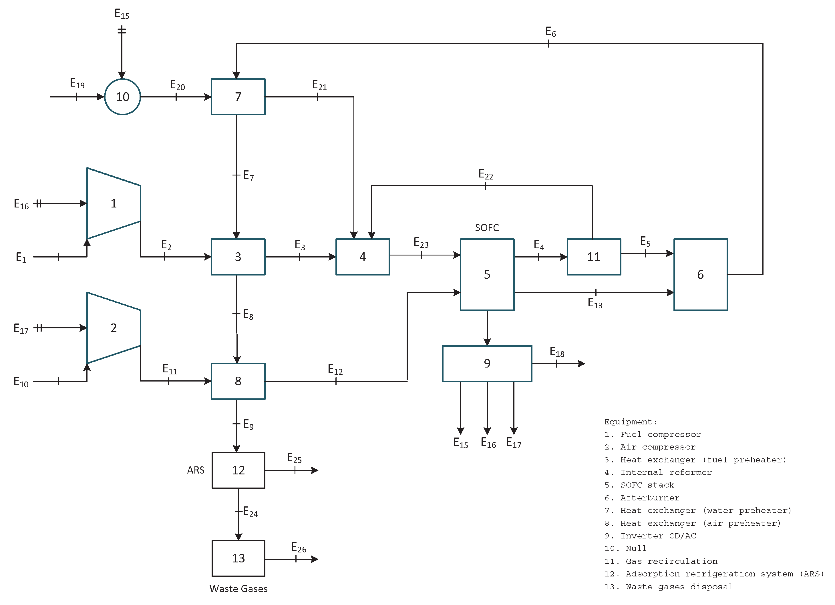
Therefore, in this research, through the application of the exergy cost theory, it is intended to propose a productive structure of the hybrid system comprised of a 500 kWe SOFC stack and of a vapor-absorption refrigeration (VAR). As a result, the exergy costs of flows and processes are obtained and analyzed.

2. System Description and Assumptions

2.1. Physical Structure

The hybrid system evaluated in this study is primarily composed of a SOFC stack and an absorption refrigeration (VAR) system, which has the capability of recovering low temperature heat (see Figure 1). The anode-supported SOFC system is constituted by 11,000 planar cells and includes direct internal reforming (4) and anodic recirculation (E 22 ). The primary fuel used in the process is natural gas (NG) whose main components are: CH 4 (93%), CO 2 (3%) and N 2 (4%). The primary fuel (E 1 ) is compressed (1) up to the pressure of the anode feed and preheated (3) to be injected into the SOFC through the endothermic steam-reforming reactor (4). A direct internal reforming (DIR) configuration is considered. Conditioned steam, generated in the heat exchanger (7), is injected in the reformer. The water for the steam, at ambient conditions, enters the system through a water pump (10). A considerable amount of SOFC exhaust gas (E 22 ) is internally recycled into the reformer, as the endothermic steam-reforming requires a high temperature source. The remaining exhaust gas (E 5 ) is burnt with the cathode exhaust (E 13 ) in the afterburner (6). The hot flue gas is used to yield steam (7), preheat the feeding primary fuel (3), as well as the cathode air (8). The air enters the system under atmospheric conditions (E 10 ), compressed (E 11 ) and then preheated (E 12 ) so as to enter the cathode side. The fundamental driving force of the SOFC is the gradient of chemical potential that is established across the two electrodes (anode and cathode) that are separated by the electrolyte layer. Thus, the reactants (fuel and air) are continuously supplied to sustain electrochemical reactions, as explained above. CD current generated in the SOFC is then transformed into AC current by means of an inverter (9) to be used as electrical power E 15 , E 16 and E 17 by the water pump (10), the fuel compressor (1) and the air compressor (2), respectively.
Thus, the exhaust gases provide the energy necessary to drive the cooling process (VAR), as shown in Figure 2. For this particular case, the refrigerant is water (H 2 O) while lithium/bromide (LiBr) is used as the absorbent. The energy provided by the exhaust gases is used to yield steam (E 29 ) in the steam generator (1) through the separation of the mixture H 2 O/LiBr (E 35 ), while the lithium bromide (E 36 ) flows back to the solution heat exchanger (2) and is expanded (4) to be sent back to the absorber (5), where it absorbs the water-vapor mix and is then pumped back to the generator. The pump (3) increases the pressure of the mixture, known as solution (Water-LiBr), and is sent through the heat exchanger (2), where a cold stream (a stream at low temperature and low concentration) receives heat from the hot stream (a stream at high temperature and high concentration). Thus, the cold stream increases its temperature and enters the generator, where it is evaporated. The evaporated water then enters the condenser (8), where its temperature is reduced and then sent to the expansion valve to reduce its pressure to enters the evaporator (6). Here it absorbs the heat from a secondary fluid to generate the cooling load or cooling effect (E 25 ). Finally, the stream water from the evaporator enters the absorber and is mixed with the high concentration solution to yield a low concentration one. However, for the purpose of the analysis, the VAR system was simplified to a single process as shown below.

2.2. Assumptions

Table 1 summarizes all the assumptions considered in the modeling of the systems described above.

3. Mathematical Models

3.1. SOFC and VAR Simulation

For the simulation of the systems described above a zero-dimension approach is considered [14]. All thermodynamic (both energy and exergy balances), electrochemical and chemical equations are modeled and simulated in the commercial Engineering Equation Solver (EES) software. However, in a previous paper, by the authors, explanation and validation of the models are provided at length [10]. To maintain model consistency, the same design data of both systems are considered here, Table 2. The reference values given to the operating variables of the hybrid system are considered in Table 3.
Table 4 unveils the absolute values of the exergy streams calculated from the thermodynamic properties of each state found throughout the entire hybrid system. Here, the energy flows from 14 to 18 correspond to AC electrical power leaving the inverter, whereas flow 25 corresponds to the refrigeration flow leaving the VAR system as a product.

3.2. Exergy Cost Equations

The methodology used for calculating the exergy costs of the system is based on the theory of the exergy cost proposed by Valero [15] and recently improved by Torres et al. [12]. Accordingly, the method comprises the following steps:
  • Definition of the productive structure
  • Application of the Fuel-Product rules of cost allocation
  • Building of the Fuel-Product table
  • Exergy cost calculation

3.2.1. Productive Structure

Industrial installations have a productive purpose, which is to generate one or several products by processing external resources. Thus, for each process, it is required to identify the flows that constitute their product streams, as well as the flows required to obtain them, called fuel streams [16]. The exergetic efficiency of a process is defined as the ratio between the exergy obtained or product and the exergy supplied as fuel. Table 5 provides the definition of the fuel and the product streams of each process in the case of the SOFC-VAR hybrid system. It is important to note that in the case of the VAR system, it has been simplified to only one process (12), as for this study only the product (the cooling load) is of interest.
The recent work of Torres et al. [12] describes an algorithm to build the productive structure diagram by means of the fuel-product table. The fuel-product table is the adjacency matrix of the productive graphs and it shows how the processes of a system interrelate among themselves and the environment, through the fuel-product definitions. For this particular case, the productive structure proposed for the SOFC-VAR system is shown in Figure 3.

3.2.2. Fuel-Product Rules of Cost Allocation

A correct allocation of costs requires the following of a series of rational rules that are essentially based on thermodynamic criteria and productive purpose [15]. These rules are summarized as follows:
  • The exergy cost is relative to the system boundaries. In other words, in the absence of external assessment, the exergy costs of the flows entering the system equal their exergy, i.e., E i * = E i .
  • The exergy costs are a conservative property. Of the costs associated with a process, both resources F u * and wastes R u * must be allocated to the production costs, i.e., P u * = F u * + R u *
  • The cost of irreversibilities in the process must be allocated to their products and proportionally allocated to their exergies
    -
    All the product streams of a process have the same unit exergy cost.
    -
    All the outputs of a product stream have the same unit exergy cost.
    -
    All the outputs of a fuel stream have the same unit cost equal to the average unit cost of the input flows of the stream.
  • The costs of waste flows must be allocated to the processes that generated them.

3.2.3. Exergy Cost Computation

The exergy costs of flows and processes are obtained by using TAESS software [17], a detailed explanation of the algorithm for which is given in [18]. The computation is carried out using the values of the reference condition given above. It is important to note that the cost of the residues is allocated to the cost of the electricity and not to the fuel as will be discussed later. Table 6 shows the exergy costs of all operational flows considered in the SOFC-VAR hybrid system.
From this table, unlike other reported works [6,7,8], the contribution that both the environment (B* e ) and the residues (B* r ) have on the total exergy cost can be seen. Likewise, the unit exergy cost (k*) is comprised of one part due to the environment k* e and another part due to the residues k* r . For example, considering flow no. 6, it is the energy flow leaving the afterburner and it can be seen that the environment accounts for 96% of its total cost, whereas the residues account for only 4%. The same analysis can be applied to the rest of the energy flows.
On the other hand, the exergy costs of the processes that make up the hybrid system are provided in Table 7. This table is revealing in several ways. First, it provides the exergy costs of fuel and product per processes, which are known for each process. Second, an original contribution of the present work is to indicate the contribution of both the environment and the residues to the final cost of the products leaving the processes.
A clear interpretation of the table can be given by using the SOFC as an example. The findings show that it has a unit exergy consumption (k) of 1.1832 kW/kW, which means that to produce each kW of electricity, the process requires the consumption of 1.18 kW of resources. On the other hand, the unit cost of the electricity produced turned out to be 1.7395 kW/kW, where the environment accounts for 98% of the entire cost and the residues have a contribution of only 2%. Of further interest is the exergy cost of the process 12 (i.e., the VAR system), the findings show a high consumption of resources of around 15 kW/kW, which reveals the low exergy efficiency of the process. This is also shown by its high unit exergy cost of 45.515 kW/kW.
What is of paramount importance, however, is to discuss the impact that some of the operating variables have on the cost of the main products of the system. Hence a detailed discussion of such matter is provided in the following section.

4. Results and Discussion

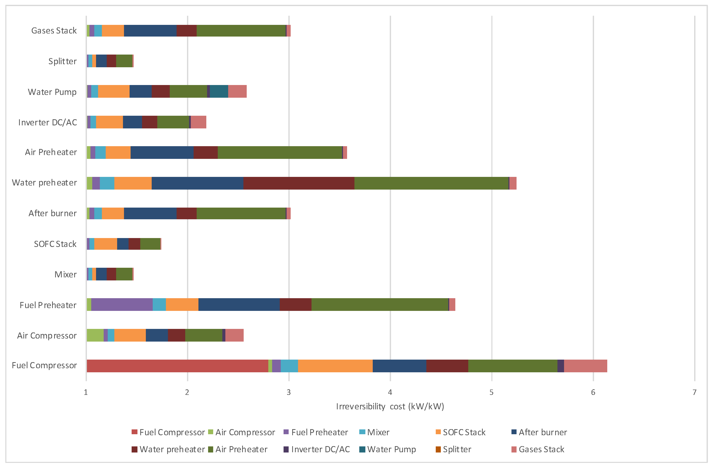
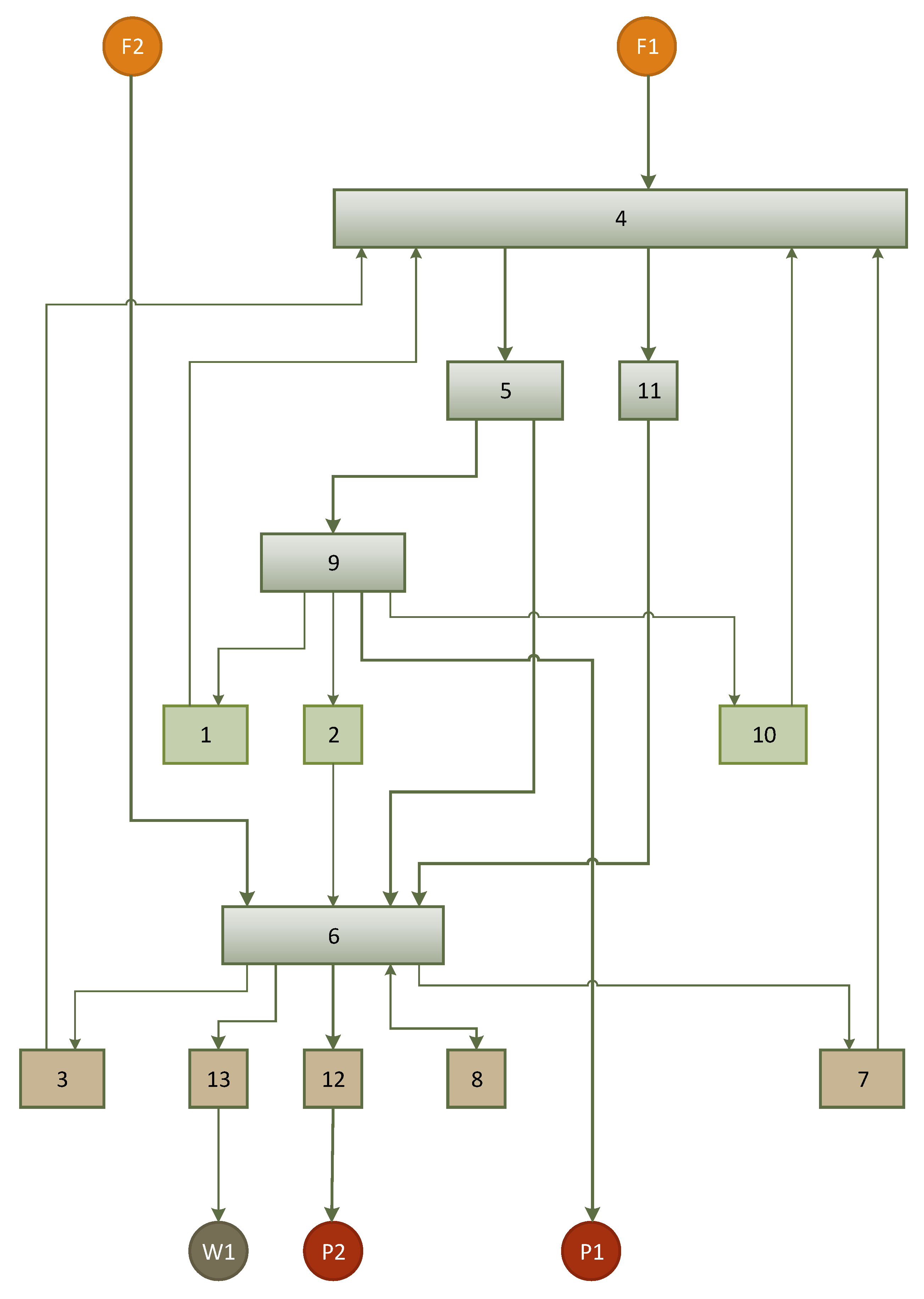
Among the benefits of the theory of exergetic cost is the fact that it allows a clear understanding of the cost formation process through the system. This can be better understood by means of Figure 4, which shows the contribution of the irreversibility generated in the i-th process to the unit cost of th product of the j-th equipment. For example, the unit product cost of the SOFC (1.74 kW/kW) is mostly comprised of the irreversibility contribution from the SOFC itself (13%), the air preheater (11%), the water preheater (7%) and the afterburner (6%), whereas the environment account for as much as 57%. Most importantly, it can be noted that the product of the fuel compressor is the most expensive, in terms of exergy consumption, because most of its contribution is due to its own inefficiency.

4.1. Integration Analysis

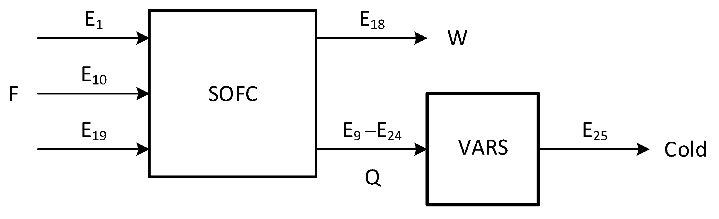
Consider the integrated system SOFC-VARS system depicted in Figure 5, where each plant is considered to be a simple process. If the exhaust gases yielded in the SOFC stack are not reused in other systems, it means that all its exergy is wasted and therefore its cost is charged to the electricity.
Alternatively, as in the case of the SOFC-VAR system, if part of the exhausted gases Q = E 9 − E 24 are reused in the VAR process, then the cost of electricity decreases from 2.74 to 2.19 kW/kW, whereas the cost of gases is around 3 kW/kW, higher than the cost of electricity. It is important to note that this cost is inclusive higher than other heat alternatives to fuel the VARS system.
Consider that the exhaust gases are a by-product of the SOFC system, the cost for which varies from 0 (waste) to 3 (product), and so the cost of electricity and electricity produced by the integrated system varies according to the following equations:
c W = F c Q · Q W c c o l d = c Q · k V A R S
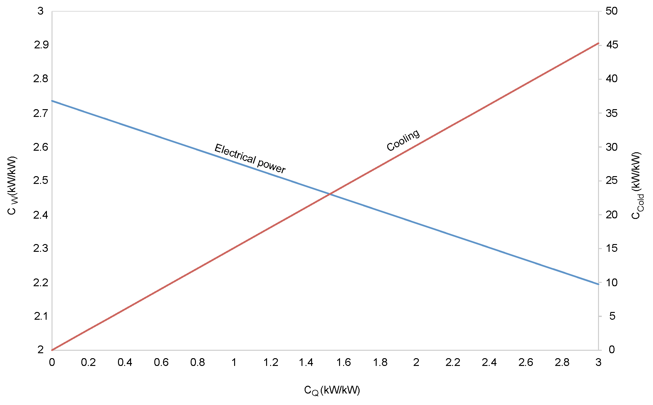
These costs variations are graphically shown in Figure 6. For example, if the cost of gases equals the cost of methane c F = c Q the cost of electricity is 2.56 kW/kW and the cost of cold is 15.1 kW/kW. On the other hand, if the cost of gases equals electricity c Q = c W = 2.32 kW/kW the cost of cold is 35 kW/kW.
Consequently, using exergy costs analysis it is possible to identify integration possibilities, efficiency improvement, and quantify the benefits due to system integration, as well as the determination of fair prices based on physical roots, see [19].

4.2. Impact of Current Density

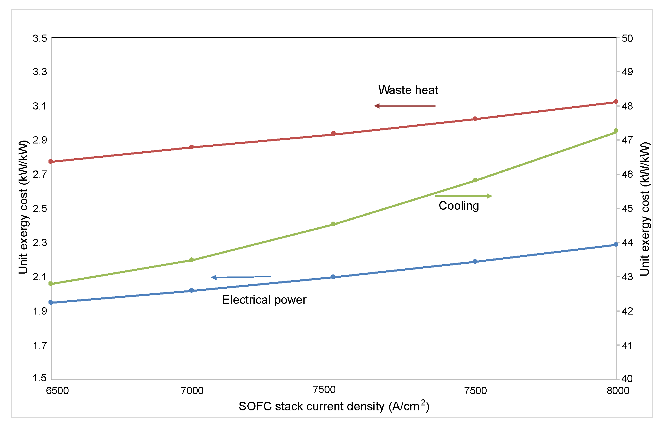
An important control parameter when it comes to operating SOFC stacks is the current density. It is interesting to study its influence on the unit exergy costs of both electricity and exhaust gases, as is shown in Figure 7. It can be noted that a variation in the current density impacts both variables equally. Yet, the unit exergy costs of the exhaust gases are 45% higher than those of the electricity. This stems from the fact that exhaust gases have gone through a series of heat exchangers before leaving the SOFC system and, as a consequence, have assimilated the irreversibilities of each piece of equipment in accordance with the principle of the cost formation process of residues [13]. In general, the unit exergy cost of both variables increases as current density rises too. It must be kept in mind that the stack voltage decreases because of the increased current density, which explains the reason the unit exergy cost also increases.
Conversely, the effect of the current density on the unit exergy cost of the refrigeration is more notable than on the electricity and the exhaust gases. On comparison, the generation of a refrigeration unit requires more resources than a unit of electricity. This is mainly due to the irreversibilities generated through the absorption refrigeration system, as it is composed of a steam generator and an evaporator and condenser; processes that, by nature, are highly dissipative. At a fixed current density of 8000 (A/cm2), the unit exergy cost of refrigeration is 45.8 (kW/kW), whereas for the electricity it is 2.1 (kW/kW). Thus, it can be deduced, from this point of view, that the production of refrigeration is not especially suitable with this configuration.

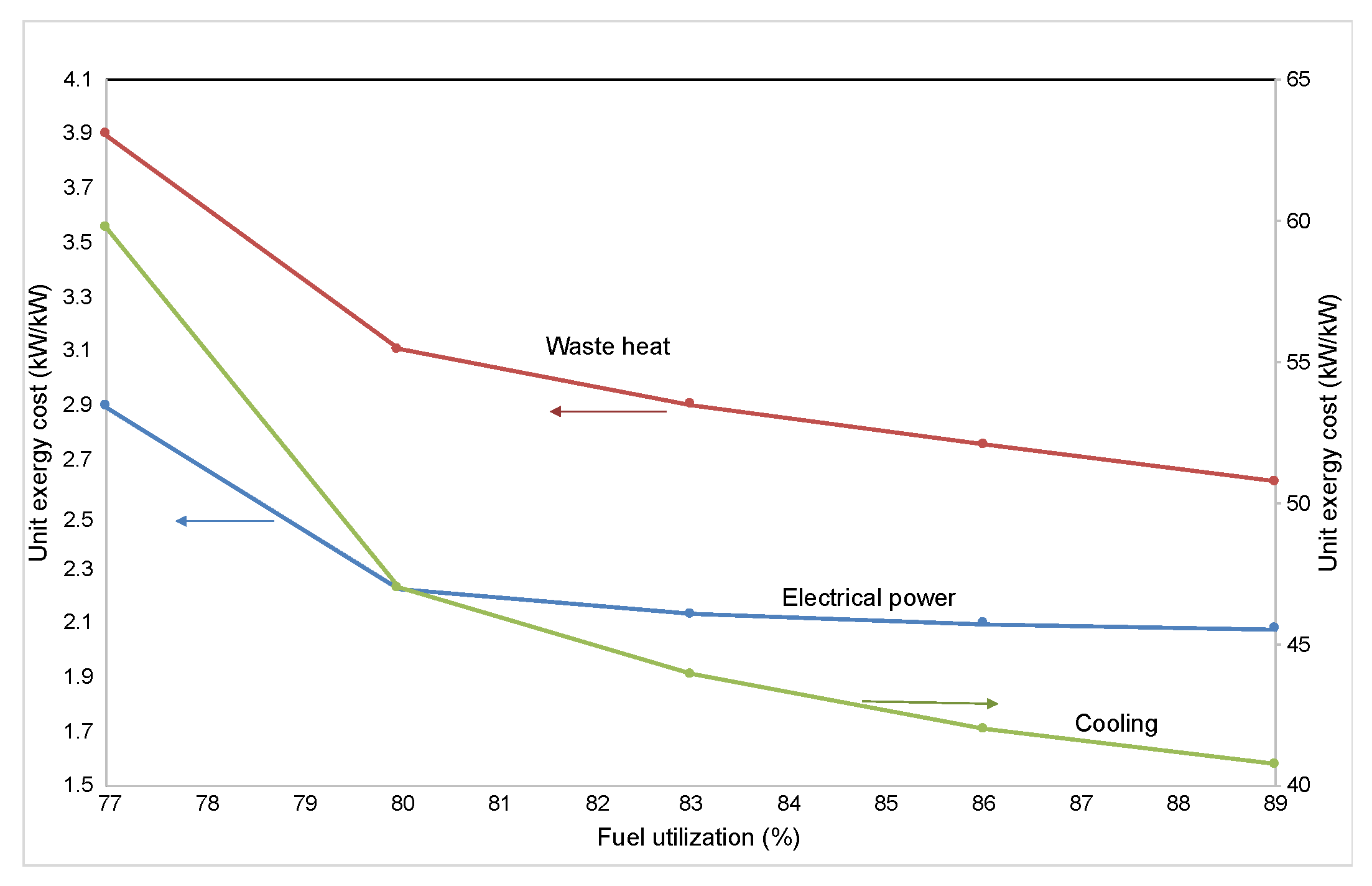
4.3. Impact of Fuel Use, FU

Another important parameter in the operation of a solid oxide fuel cell stack is the fuel use. However, this parameter cannot be physically manipulated but, in practice, it is calculated by Faraday’s Law using the current generated in the stack [20]. Thus, the effect of fuel use on the unit exergy costs is explained as follows. First, the existing correlation between FU and the unit exergy costs of electricity and exhaust gases is provided in Figure 8 at a fixed current density (8000 A/cm 2 ) and stack temperature difference (100 K). It can be noted that the unit exergy cost of electricity is not sensitive to FU variations above 80%. Yet, a noticeable increase of up to 28% is found when FU drops below 80%. This is because at low FU ratios, less hydrogen is converted into power and higher additional air flow is required for cooling. Consequently, more power is required in the compressor, and therefore the electrical efficiency of the stack decreases, hence the high unit exergy cost at low FU ratios. In contrast, the unit exergy cost of the exhaust gases is more sensitive to FU variations. The reason for this is because, as previously mentioned, this exergy stream is accompanied by the inefficiencies of the heat exchangers located upstream. In comparison, between both costs the minimum difference is 20% at 89% of FU, whereas the maximum difference is 30% at 77% of FU.
Most interestingly, it is the remarkable impact that FU has on the unit exergy cost of the refrigeration. It falls sharply and follows the same trend as the unit costs of electricity and exhaust gases but in a greater proportion. For example, at a fixed 83% FU, each unit of refrigeration costs as much as 44 kW of resource consumption, while the unit exergy cost of electricity is around 2.2 kW/kW. As previously mentioned, the production of cooling is not viable in this configuration.

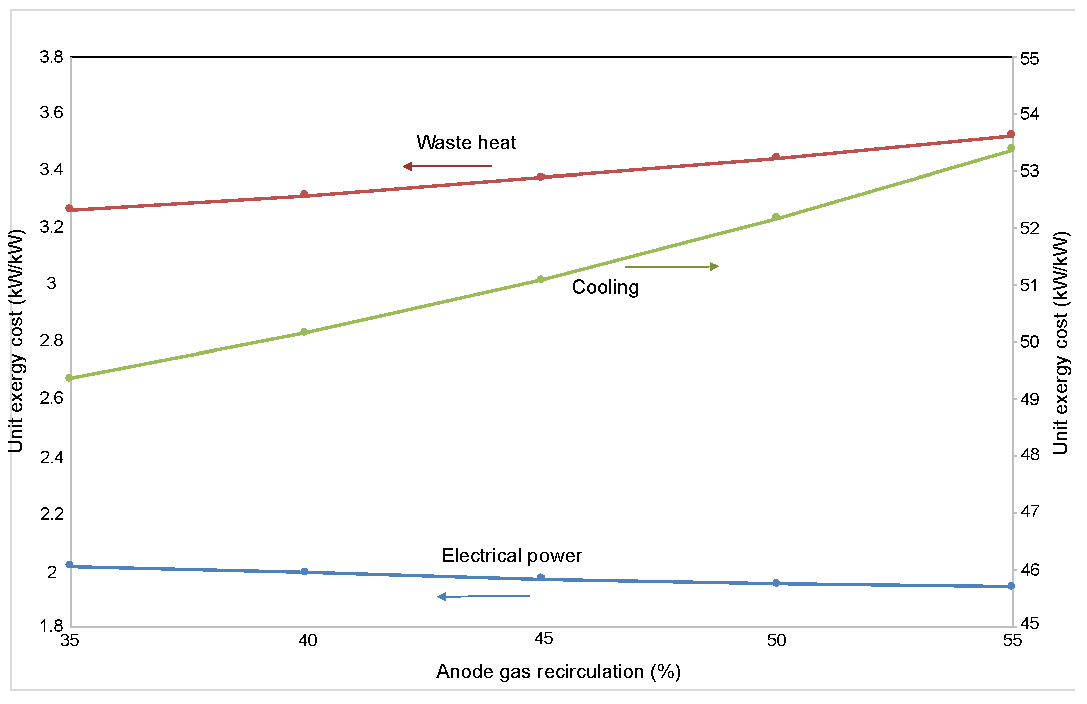
4.4. Impact of Anode Gas Recirculation

The analysis of anode gas recirculation is of particular interest, as apart from providing the heat for the steam-reforming reaction, it is used to control the stack difference temperature and hence the air for the cooling rate. Thus, in terms of costs, Figure 9 unveils the unit exergy cost of electricity and exhaust gases as a function of the anode gas recirculation. Interestingly, two trends in the costs can be observed as the percentage of gas recirculation rises. On the one hand, the unit exergy cost of electricity slightly decreases, which is largely due to the higher fuel use as a result of the anode gas recirculation increase and hence the improvement in the stack efficiency as investigated in the work of Peters et al. [21]. On the other hand, the unit exergy cost of the exhaust gases increases because they have lower energy availability as a result of bifurcation or by-pass and hence its unit cost increases. However, an increase in 25% in the anode gas recirculation does not have a notable effect on the unit exergy costs, this is lower than 1%.
On the contrary, the same 25% increase has a more noticeable effect on the unit exergy cost of the product of the refrigeration system of approximately 4.7%. In this case, the difference between the highest and the lowest unit exergy cost of refrigeration is at least 7.5%. Hence, the effect of the anode gas recirculation is greater in downstream equipment than in the same cell.

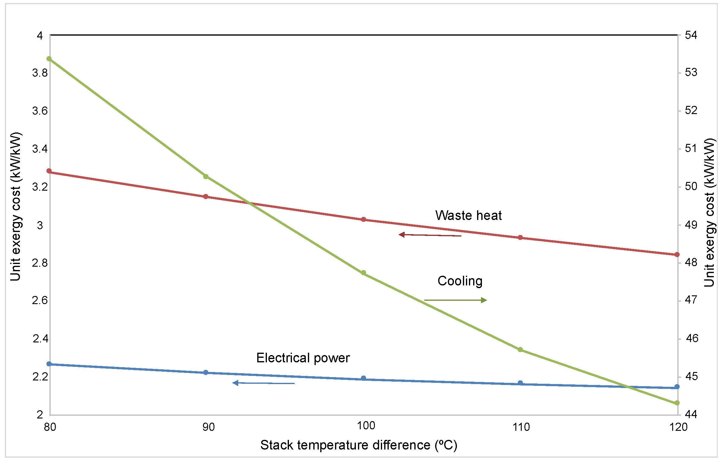
4.5. Impact of the Stack Temperature Difference

The control of the temperature difference across the stack is of great importance, because it can avoid causing large thermal stresses that can damage the entire SOFC stack, as well as allowing control of the amount of cooling air entering the system. However, it is valuable to discover how the temperature control measures positively or negatively affect the exergy costs of products. Therefore, the analysis of Figure 10 allows the determination that the unit exergy costs for the exhaust gases are more sensitive to changes in the stack temperature difference than the electrical ones. As expected, increasing the temperature difference across the SOFC stack from 90 to 110 C represents a 6.5% decrease in the unit exergy costs of the exhaust gases, while in the case of electricity, it only represents a 1% decrease. The reason the unit exergy costs decrease is mainly down to the reduction of the energy consumption of the air compressor. The surplus air flow injected to the SOFC stack is inversely related to the temperature difference across the stack, and so if the surplus air is reduced, then so is the power consumption of the compressor [20].
Likewise, the unit exergy cost of the refrigeration drops as the temperature difference across the stack increases. However, for the same case as assumed above, the impact on the unit exergy cost of the refrigeration is 10%. Apparently, if the temperature difference across the stack continues to increase, the unit exergy costs of the products would fall. Yet, for operational and safety reasons, the SOFC stack cannot be operated at high temperature difference [20,22].

5. Conclusions

The application of the exergy cost theory to a hybrid system based on an SOFC stack and on a VAR system has permitted to make several contributions to the current literature:
  • The first productive structure of a Solid Oxide Fuel Cell stack coupled to a Vapor-Absorption Refrigeration system is here reported. It depicts the integration of the different components by means of resources, products, and residues flows.
  • The application of this approach has shown that for a reference case, the unit exergy costs of electrical power, cooling, and waste heat are 2.192 kW/kW, 3.014 kW/kW and 45.515 kW/kW, respectively.
  • This approach has also permitted to know the contribution of the environment and the residues to the cost of the product. In the case of the electrical power, the contribution of the environment was 80% and the other 20% was provided by the residues. Meanwhile, for the unit exergy cost of cooling, the environment accounts for 96% and the residues for only 4%.
  • The analysis of the impact of current density on the exergy costs has revealed that the unit exergy cost of cooling turned out to be the more sensitive to it than the exergy cost of the electrical power and the exhaust gases.
  • The study of the effect of the fuel use on the unit exergy costs has shown that below 80%, the unit exergy cost of the cooling is the most sensitive of all. However, above 80%, the unit exergy cost of the electrical power has remained constant, 2.1 kW/kW.
  • In the case of the percentage of the anode gas recirculation, the results have revealed that its effect is greater on the unit exergy cost of the cooling and exhaust gases then on the electrical power.
  • The analysis of the impact of the stack temperature difference on the unit exergy costs has been of further interest. The results have revealed a steeper fall of the unit exergy cost of cooling as the temperature difference begins to increase. In thermodynamic terms, this situation would be ideal but due to operational and safety reasons, the stack temperature difference cannot reach higher values.
Altogether, the paper has provided an alternative to conventional analysis for identifying integration possibilities, efficiency improvements, quantification of benefits, and providing a physical basis for prices. Finally, the findings of this research have been limited due to the lack of information in current literature on the physical characteristics of a real solid oxide fuel cell stack.

Author Contributions

Ideas, formulation of overarching research goals and aims, creation of models, writing of the initial draft, V.H.R.-H.; design of methodology, application of mathematical algorithms to solve the problem, software development, C.T.; verification of the overall reproducibility of results, C.T. and A.Z.-A.; management to scrub data and maintain research data, A.Z.-A.; preparation of the published work specifically data presentation, A.Z.-A. and M.A.G.-M.

Funding

Part of this research was funded by CONACYT through the program Sabbatical Stays Abroad. Publication costs were covered by the Program for the Strengthening of Educational Quality (PFCE) 2019 of the University of Guanajuato.

Acknowledgments

We would like to thank all the support and knowledge provided by the Institut für Energie- und Klimaforschung von Forchungszentrum Jülich during my sabbatical stay. As well, V. H. Rangel-Hernandez want to thank to the University of Guanajuato for the sabbatical stay granted during the period 2018–2019.

Conflicts of Interest

The authors declare no conflict of interest.

References

  1. Krishna, K.S.; Kumar, K.S. A review on hybrid renewable energy systems. Renew. Sustain. Energy Rev. 2015, 52, 907–916. [Google Scholar] [CrossRef]
  2. Chinda, P.; Brault, P. The hybrid solid oxide fuel cell (SOFC) ad gas turbine (GT) systems steady state modeling. Int. J. Hydrog. Energy 2012, 37, 9237–9248. [Google Scholar] [CrossRef]
  3. Alvarez, T.; Valero, A.; Montes, J.M. Thermoeconomic analysis of a fuel cell hybrid power system from the fuel cell experimental data. Energy 2006, 31, 1358–1370. [Google Scholar] [CrossRef]
  4. Rokni, M. Thermodynamic and thermoeconomic analysis of a system with biomass gaisfication, solid oxide fuel cell (SOFC) and stirling engine. Energy 2014, 76, 19–31. [Google Scholar] [CrossRef]
  5. Baghernjad, A.; Yaghoubi, M.; Jafarpur, K. Exergoeconomic comparison of three novel trigeneration systems using SOFC, biomass and solar energies. Appl. Therm. Eng. 2016, 104, 534–555. [Google Scholar] [CrossRef]
  6. Lee, Y.D.; Ahn, K.Y.; Morosuk, T.; Tsatsaronis, G. Exergetic and exergoeconomic evaluation of an SOFC-Engine hybrid power generation system. Energy 2018, 145, 810–822. [Google Scholar] [CrossRef]
  7. Cheddie, D.F. Thermo-economic optimization of an indirectly coupled solid oxide fuel cell/gas turbine hybrid power plant. Int. J. Hydrog. Energy 2011, 36, 1702–1709. [Google Scholar] [CrossRef]
  8. Arsalis, A. Thermoeconomic modeling and parametric study of hybrid SOFC-gas turbine-steam turbine power plants ranging from 1.5 to 10 MWe. J. Power Sources 2008, 181, 313–326. [Google Scholar] [CrossRef]
  9. Wang, J.; Yan, Z.; Ma, S.; Dai, Y. Thermodynamic analysis of an integrated power generation system driven by solid oxide fuel cell. Int. J. Hydrog. Energy 2012, 37, 2535–2545. [Google Scholar] [CrossRef]
  10. Rangel-Hernandez, V.; Ramirez-Minguela, J.; Blum, L.; Nino-Avendano, A.; Ornelas, R. Parametric analysis of the exergoeconomic variables of a solid oxide fuel cell (SOFC) coupled with a vapour-adsorption refrigeration system (VARS). Energy Convers. Manag. 2018, 172, 428–437. [Google Scholar] [CrossRef]
  11. Venkataraman, V.; Pacek, A.W.; Steinberger-Wickens, R. Coupling of a solid oxide fuel cell auxiliary power unit with a vapour absoprtion refrigeration system for refrigerated truck application. Fuel Cells 2016, 16, 273–293. [Google Scholar] [CrossRef]
  12. Torres, C.; Valero, A. A new methodology to compute exergy cost. In Proceedings of the ECOS 2018: The 31st international conference on Efficiency, Cost, Optimization, Simulation and Environmental Impact of Energy Systems, Guimaraes, Portugal, 17–21 June 2018. [Google Scholar]
  13. Torres, C.; Valero, A.; Rangel-Hernandez, V.; Zaleta, A. On the cost formation process of residues. Energy 2008, 33, 144–152. [Google Scholar] [CrossRef]
  14. Minh, N. Systems Designs and Applications. In High-Temperature Solid Oxide Fuel Cells for the 21st Century: Fundamentals, Design and Applications; Kendall, K., Kendall, M., Eds.; Elsevier Ltd.: Oxford, UK, 2016; pp. 283–327. [Google Scholar]
  15. Valero, A.; Lozano, M.; Munoz, M. A General Theory of Exergy Saving. I: On the Exergetoc Cost. In Computer-Aided Engineering and Energy Systems: Second Law Analysis and Modelling; Gaggioli, R., Ed.; ASME: New York, NY, USA, 1986; Volume 3, pp. 1–8. [Google Scholar]
  16. Tsatsaronis, G.; Winhold, M. Exergoeconomic analysis and evaluation of energy-conversion plants—I. A new general methodology. Energy 1985, 10, 69–80. [Google Scholar] [CrossRef]
  17. TAESS. TAESS—Thermoeconomic Analysis of Energy Systems Software, 2009–2019; University of Zaragoza & CIRCE. Available online: http://www.exergoecology.com/taess (accessed on 9 September 2019).
  18. Torres, C.; Perez, E.; Valero, A. Guidelines to Develop Software for Thermoeconomic Analysis of Energy Systems. In Proceedings of the ECOS 2018: The 31st international conference on Efficiency, Cost, Optimization, Simulation and Environmental Impact of Energy Systems, Guimares, Portugal, 17–21 June 2018; pp. 435–453. [Google Scholar]
  19. Valero, A.; Usón, S.; Torres, C.; Valero, A. Application of Thermoeconomics to Industrial Ecology. Entropy 2010, 12, 591–612. [Google Scholar] [CrossRef]
  20. Blum, L.; Riensche, E. Fuel Cells—Solid Oxide Fuel Cells: Systems. In Encyclopedia of Electrochemical Power Sources; Garche, J., Ed.; Elsevier: Amsterdam, The Netherlands, 2009; pp. 99–119. [Google Scholar] [CrossRef]
  21. Peters, R.; Deja, R.; Engelbracht, M.; Frank, M.; Nguyen, V.N.; Blum, L.; Stolten, D. Efficiency analysis of a hydrogen-fueled solid oxide fuel cell system with anode off-gas recirculation. J. Power Sources 2016, 328, 105–113. [Google Scholar] [CrossRef]
  22. Qingping, F.; Blum, L.; Peters, R.; Peksen, M.; Batfalsky, P.; Stolten, D. SOFC stack performance under high fuel utilization. Int. J. Hydrog. Energy 2015, 40, 1128–1136. [Google Scholar] [CrossRef]
Figure 1. Schematic diagram of the solid oxide fuel cell-vapor absorption refrigeration hybrid system.
Energies 12 03476 g001
Figure 2. Schematic diagram of vapor-absorption refrigeration system: simplification.
Energies 12 03476 g002
Figure 3. Productive structure of the SOFC-VARS hybrid system.
Energies 12 03476 g003
Figure 4. Breakdown of the irreversibility cost by process.
Energies 12 03476 g004
Figure 5. SOFC-VARS Integrated System.
Energies 12 03476 g005
Figure 6. Variation of the unit exergy cost of electricity and refrigeration as a function of by-product exhausted gas costs.
Energies 12 03476 g006
Figure 7. Variation of the unit exergy cost of electricity, exhaust gases and refrigeration as a function of the current density.
Energies 12 03476 g007
Figure 8. Variation of the unit exergy cost of electricity and exhaust gases as a function of the fuel use (FU).
Energies 12 03476 g008
Figure 9. Variation of the unit exergy cost of electricity and exhaust gases as a function of the anode gas recirculation.
Energies 12 03476 g009
Figure 10. Variation of the unit exergy cost of electricity and exhaust gases as a function of the stack temperature difference.
Energies 12 03476 g010
Table 1. System modeling assumptions.
SOFCVAR
Air composition: 79% N 2 and 21% O 2 .Fluid refrigerant: water
All gases are considered to be ideal gases.Pressure in the generator and the condenser are equivalent.
Gas mixture at the SOFC stack fuel channel exit is in chemical equilibrium.Pressure in the evaporator and the absorber are equivalent.
Heat loss from the SOFC stack to the surroundings is negligible.
The constant resistances between the SOFC components are negligible.
The temperature of the fuel and air at the inlet channels of the SOFC stack is the same.
The temperature of the fuel and air at the outlet channels of the SOFC stack is the same.
Unreacted gases are considered fully oxidized in the afterburner
Table 2. Design parameters for the SOFC-VAR system.
Design ParameterValue
Anode exchange current density, i o a 0.65A/cm 2
Cathode exchange current density, i o c 0.25A/cm 2
Effective diffusivity: anode side, D a e f f 0.2cm 2 /s
Effective diffusivity: cathode side, D c e f f 0.05cm 2 /s
Anode thickness, La500 μ m
Cathode thickness, Lc50 μ m
Electrolyte thickness, Le10 μ m
Number of cells, N11,000-
Active surface area0.01m 2
AC-DC inverter efficiency97%
Isentropic efficiency of fuel and air compressor85%
Isentropic efficiency of pump water85%
Table 3. Reference control parameters for the SOFC-VAR system.
Operating VariableValueUnit
SOFC
Inlet-outlet temperature difference100K
Inlet temperature1000K
Fuel use0.85-
Steam-to-carbon ratio2.5-
SOFC stack pressure drop2%
Heat exchangers pressure drop3%
Afterburner pressure drop (piping)5%
VARS
Evaporator inlet temperature295K
Condenser inlet temperature300K
Absorber inlet temperature298K
Mass flow evaporator4kg/s
Mass flow condenser5kg/s
Mass flow absorber2kg/s
Heat transfer coefficients
Steam generator, absorber0.85kW/m 2 K
Condenser1.4kW/m 2 K
Evaporator1.5kW/m 2 K
Table 4. Reference operating values for the simulation of the SOFC-VAR system.
IDP (kPa)T (C)m (kg/s)Exergy (W)
1101.3298.225.631,136,920
2124.1100025.631,137,240
3121.6100025.631,166,570
41181100159.8423,650
51181100159.6423,230
6112.1116929771,634,430
7109.8110229771,452,310
8107.6108729771,407,150
9105.5466.12977142,917
10101.3298.2289012,871.6
11124.1319289065,231
12121.6100028901,130,230
13118110028181,329,700
14---493,090
15---1.65829
16---896.01
17---60,957
18---421,370
19101.3298.261.733084.02
20124.1298.261.733085.43
21121.6100061.73107,736
2211811000.1598420.00
23121.6100087.521,243,090
24103.4393.6297766,878
25---5035
26101.32980.866,878
Table 5. Definition of the Fuel-Product table for the SOFC-VAR system.
IDProcessFuelProduct
0EnvironmentE 18 + E 25 + E 26 E 1 + E 10 + E 19
1Fuel CompressorE 16 E 2 − E 1
2Air CompressorE 17 E 11 − E 10
3Fuel PreheaterE 7 − E 8 E 3 − E 2
4MixerE 3 + E 21 + E 22 E 23
5SOFC StackE 23 − E 4 (E 13 − E 12 ) + E 14
6After burnerE 5 + E 13 E 6
7Water preheaterE 6 − E 7 E 21 − E 20
8Air PreheaterE 8 − E 9 E 12 − E 11
9Inverter DC/ACE 14 E 15 + E 16 + E 17 + E 18
10Water PumpE 15 E 20 − E 19
11SplitterE 4 E 5 + E 22
12ARSE 9 − E 24 E 25
13Gases StackE 24 E 26
Table 6. Exergy costs of the flows part of the SOFC-VAR system.
IDB (W)B * (W)B e * (W)B r * (W)k * (W/W)k e * (W/W)k r * (W/W)
11,136,9201,136,9201,136,9200110
21,137,2401,138,884.21,138,488.6395.61.00141.00110.0003
31,166,5701,274,988.51,269,686.15302.31.09291.08840.0045
4423,650622,843.5614,289.68553.91.47021.450.0202
5423,230622,226613,680.68545.41.47021.450.0202
61,634,4304,925,883.24,748,299.2177,5843.01382.90520.1087
71,452,3104,377,005.74,219,209.4157,796.33.01382.90520.1087
81,407,1504,240,901.54,088,011.8152,889.63.01382.90520.1087
9142,917430,726.6415,198.415,528.23.01382.90520.1087
1012,871.612,871.612,871.60110
1165,231146,498.7119,586.826,911.92.24581.83330.4126
121,130,2303,956,673.53,792,400.3164,273.33.50083.35540.1453
131,329,7004,303,657.24,134,618.6169,038.63.23663.10940.1271
14493,090857,743.9845,96411,779.91.73951.71560.0239
151.73.62.90.72.19221.75070.4415
168961964.21568.6395.62.19221.75070.4415
1760,957133,627.1106,715.226,911.92.19221.75070.4415
18421,370923,707.5737,677.2186,030.32.19221.75070.4415
193084308430840110
203085.43087.73086.90.71.00071.00050.0002
21107,736551,965.2532,176.719,788.45.12334.93960.1837
22420617.56098.51.47021.450.0202
231,243,0901,827,571.11,802,471.925,099.21.47021.450.0202
2466,878201,558.5194,2927266.43.01382.90520.1087
255035229,168.1220,906.38261.845.51543.87411.6409
2666,878201,558.5194,2927266.43.01382.90520.1087
Table 7. Exergy costs for each process of the SOFC-VAR system.
IDP * (W)P e * (W)P r * (W)F * (W)R * (W)k (J/J)k P * (J/J)k P , e * (J/J)k P , r * (J/J)k F * (J/J)
11964.21568.6395.61964.202.86.13814.90191.23622.1922
2133,627.1106,715.226,911.9133,627.101.16422.55212.03810.5142.1922
3136,104.3131,197.54906.7136,104.301.53974.64044.47320.16733.0138
41,827,571.11,802,471.925,099.21,827,571.101.02541.47021.450.02021.4337
51,204,727.61,188,182.316,545.31,204,727.601.18321.73951.71560.02391.4702
64,925,883.24,748,299.2177,5844,925,883.201.07253.01382.90520.10872.8101
7548,877.5529,089.819,787.7548,877.501.74035.24495.05580.18913.0138
83,810,174.93,672,813.5137,361.43,810,174.901.18713.57763.44870.1293.0138
91,059,302.4845,964213,338.4857,743.9201,558.51.02042.19221.75070.44151.7395
103.62.90.73.601.17732.58082.06110.51982.1922
11622,843.5614,289.68553.9622,843.5011.47021.450.02021.4702
12229,168.1220,906.38261.8229,168.1015.102145.51543.87411.64093.0138
13201,558.5194,2927266.4201,558.5013.01382.90520.10873.0138

