Article

Fault Characteristic and Low Voltage Ride-Through Requirements Applicability Analysis for a Permanent Magnet Synchronous Generator-Based Wind Farm

1
College of Electrical Engineering, Zhejiang University, Hangzhou 310027, China
2
Zhejiang Provincial Key Laboratory of Electrical Machine Systems, Zhejiang University, Hangzhou 310027, China
3
Inner Mongolia Electric Power Science and Research Institute, Inner Mongolia Power Group Co. Ltd., Hohhot 010020, China
*
Author to whom correspondence should be addressed.
Energies 2019, 12(17), 3400; https://doi.org/10.3390/en12173400
Submission received: 2 August 2019 / Revised: 30 August 2019 / Accepted: 31 August 2019 / Published: 3 September 2019
(This article belongs to the Section F: Electrical Engineering)

Abstract

:
As the penetration of wind energy is being dramatically increased, the impact of wind energy on the power system should be roundly studied, especially for the fault characteristics analysis and applicability analysis of low voltage ride-through (LVRT) requirements for a whole wind farm (WF) and an individual wind turbine generator (WTG). This paper firstly describes a detailed modeling of a permanent magnet synchronous generator (PMSG)-based WF and analyzes the fault characteristics of the WF under various fault conditions. The validation of the fault characteristics analysis is carried out with the EMTP-RV generated data, with the consideration of different fault positions, fault types, and wind speeds. The relay protection and the related grid code are also taken into account. In addition, the applicability analysis of LVRT requirements for a WF and a WTG is also implemented, from the points of minimal grid-connection time and minimal dynamic reactive current support ability. The fault characteristic analysis of a PMSG-based WF could be helpful for developing new control or protection methods for a PMSG-based WF. Meanwhile, the applicability analysis of LVRT requirements could serve as a reference for WTG manufacturers, WF administrators, and grid operator.

Graphical Abstract

1. Introduction

To reduce the emission of green gases, the Copenhagen Climate Council was held to promote a new climate treaty to replace the Kyoto Protocol from 1997 [1]. Although the Copenhagen Accord was not ultimately approved, it sent an important signal that many countries are attempting to reduce their dependence on fossil energy by developing renewable energies, such as wind, solar, bio-, and hydraulic energy. In addition, the World Wildlife Fund for Nature released “The Energy Report [2]”, which outlined how the world can be powered by 100% renewable energy by 2050.
Among these renewable energy resources, wind energy has become the most prospective alternative due to its abundant potential sources and advances in power generation technologies over the last decade. The global total installation of wind power remains above 500 GW and according to the prediction of Global Wind Energy Council (GWEC), the total cumulative installations will reach 840 GW by the end of 2022 [3]. Moreover, the capacity of individual wind farms (WFs) have become larger and larger. Korea has begun the construction of a 2.5 GW offshore WF near the western coast that is expected to be complete in 2019 [4]. At present, the doubly fed induction generator (DFIG) and the permanent magnet synchronous generator (PMSG) are two main kinds of variable speed wind turbine generators (WTGs). Compared with the DFIG, the PMSG will be more widely used, due to some obvious advantages. The gearbox, which may be easily broken, is omitted in the PMSG, which can improve the efficiency and reliability of the PMSG. What is more, the utilization of a full-scaled power converter makes the control strategies of a PMSG-based WTG more powerful and much easier.
Nowadays, the potential for large-scale exploitation of wind energy is huge, but the impact of the wind power generation on the power system should be carefully deliberated with more wind power generation flooding into the power system, the demand for a better understanding of the factors affecting the behaviors of a WF under fault conditions is greater, so it is essential to analyze the fault characteristics of a WF. The fault characteristic analysis and related researches of a PMSG-based WF have been presented before [5,6,7,8,9,10,11,12,13,14,15,16,17].
The characteristic based on direct-driven wind energy conversion using PMSG during grid voltage sag has been simulated and studied in [5], wherein the grid voltage sag was simplified to the gird side converter voltage sag and the topology of a WF was ignored. The short-circuit current characteristics of direct-drive permanent magnet wind turbine were simulated and studied in [6], where only three-phase (3P) fault on the high voltage side was considered and the current characteristics were analyzed. However, unsymmetrical faults, i.e., single-line-to-ground (SLG), double line-to-ground (DLG), and line-to-line (LL) faults were not considered. The performance analysis of a PMSG wind turbine during short circuit faults was presented in [7], where the 3P and SLG faults were considered and the topology of a WF was simplified, as it was in [6]. The transient stability analysis of a variable speed wind turbine (VSWT) using a field excited synchronous generator was presented in [8], where only SLG faults were considered. The transient stability analysis of a permanent magnet variable speed synchronous wind generator during symmetrical and unsymmetrical faults was presented in [9], where all fault type and simple position difference were considered. The fault characteristics of collecting power lines in PMSG wind farm were simulated and studied in [10], which focused on the faults in the power collection system inside a PMSG-based WF. Many methods for fault detection or diagnosis were presented in [11,12,13,14], all of which focused on the fault characteristics inside the PMSG or the full power converter rather than the fault characteristics of a WF during WF or power system faults. Besides, some characteristic study and advanced control methods were proposed during faults, where only severe 3P faults were considered [15,16,17]. In brief, specialized and comprehensive fault characteristic analysis of a PMSG-based WF is still insufficient.
Many countries have developed their own grid codes for wind power interconnection to mitigate the possible negative impacts of a WF [18,19]. One of the significant requirements for a WF in these grid codes is the low voltage ride-through (LVRT) capability, which requires a WF to stay connected to the grid for a short time when the voltage drops [20]. Obviously, it is what the grid asks of a WF, to maintain grid stability to a certain extent. However, WF owners or operators usually transfer the grid demand for the LVRT capability of a WF, which considers the voltage of the point of common coupling (PCC) of the whole WF, directly to WTGs and their manufacturers, which can only consider the WTG terminal voltages. In addition, it seems that the PRC National Standard to be implemented for wind turbines test procedure of voltage fault ride through capability will approve this practice tacitly [21], which requires the same LVRT capability for WTGs as that for a WF [20], while it is a rigor to WTGs and this procedure should be deliberated carefully.
In this paper, a typical modeling and topology construction of a PMSG-based WF is described. The machine side converter (MSC) regulates optimal electrical torque to realize maximum power point tracking (MPPT) at low wind speed and regulates constant electrical torque at high wind speed. The grid side converter (GSC) maintains the direct current (DC) voltage stable and controls the reactive power output. The pitch control limits the rotor angular velocity not over the rated. This paper analyzes the fault characteristics of a PMSG-based WF under various fault conditions. The validation of fault characteristics analysis is carried out with the EMTP-RV generated data, with the consideration of different fault positions, fault types, and wind speeds. The relay protection and the related grid code are also taken into account. Besides, the applicability analysis of LVRT requirements for a WF and a WTG is presented, from the points of both minimal grid-connection time and minimal reactive current support.
A detailed modeling of a PMSG-based WTG is firstly presented in Section 2. A typical control strategy of a PMSG-based WTG is described in Section 3. The relay protections of a PMSG-based WTG or WF are given in Section 4. The model system of a PMSG-based WF is introduced in Section 5. Case studies concerning fault characteristics are shown in Section 6. The LVRT requirements for a WTG and a WF are discussed in Section 7. Finally, the concluding remarks are made in Section 8.

2. Modeling of a PMSG-Based WTG

The model of a PMSG-based WTG consists of the wind turbine, drive shaft, PMSG, and back-to-back converter models, which are shown in Figure 1. The wind turbine model captures the power from wind and converts it into mechanical power transmitted to the drive shaft model; the drive shaft model transfers the mechanical power from the wind turbine model to the PMSG model; the PMSG model converts the mechanical power into the electrical power and transmits it to the back-to-back converter model; the back-to-back converter model transmits the maximal or required power to the grid.

2.1. Wind Turbine Modeling

Wind turbines cannot capture all passing wind energy. The mechanical power (Pt) extracted from the wind is given in (1) [22,23].
P t = P w C p ( λ , β ) = 1 2 ρ S v 3 C p ( λ , β )
where Pw, Cp, λ, β, ρ, S, and v are wind power, wind power coefficient, tip speed ratio, pitch angle, air density, wind turbine swept area, and wind speed, respectively. λ is given as:
λ = ω t R v
where ωt and R are the angular velocity and the radius of the wind turbine, respectively.

2.2. Drive Shaft Modeling

The drive shaft takes an effect in transferring the mechanical power or torque. In a PMSG-based WTG with large capacity, due to the large inertia moments on the both sides of the drive shaft, it can cause distortion and relaxation to the drive shaft, which may affect the transient process.
The paper uses 2-mass model, which regards wind turbines and the rotor as two masses with large inertia moments, the state equation in per-unit value is defined and given in (3) [24].
2 H t d ω t d t = T t D S D t × ω t T r , 2 H r d ω r d t = T r D S D r × ω r T e , d θ Δ d t = 2 π f p ( ω t ω r ) , T r = K θ Δ + D S M ( ω t ω r ) .
where Ht and Hr are inertia time constants of the turbine and the rotor; ωt and ωr are angular velocities of the wind turbine and the rotor; Tt, Tr and Te are the input torque of wind turbine, output torque of drive shaft or input torque of rotor, and electromagnetic torque of PMSG; θ is the torsion angle; f is the frequency base; p is the polar logarithm of PMSG; K is the rigidity coefficient; DSDt, DSDr, and DSM are the self-damping coefficients of the wind turbine and the rotor, and the mutual damping coefficient between each other. The units of the quantities in the equation are all per unit except that the units of K, θ, and f are pu/rad, rad, and Hz, respectively.

2.3. PMSG Modeling

The PMSG model using the rotor-flux-oriented frame is defined and given in (4). The positive direction is specified as follows: d-axis is oriented to rotor flux, q-axis is 90° electrical angle ahead of d-axis, and the direction of voltage and current conforms to the generator model [25].
u s d = ( L s d s + r s ) i s d + ω s e L s q i s q , u s q = ( L s q s + r s ) i s q ω s e L s d i s d ω s e ψ f .
where usd and usq are the stator d- and q-axis voltages; isd and isq are the stator d- and q-axis currents; rs is the stator resistance; Lsd and Lsq are the stator d- and q- axis inductances; s is a complex variable; ψf is the permanent magnet flux; ωse is the electrical angular velocity of the rotor.
The electromagnetic torque builds a bridge between mechanical and electrical part. It not only takes part in torque transferred in (3), but also relates to electrical quantities in (4), as shown in (5).
T e = 3 2 L s q L s d i s d i s q ψ f i s q p

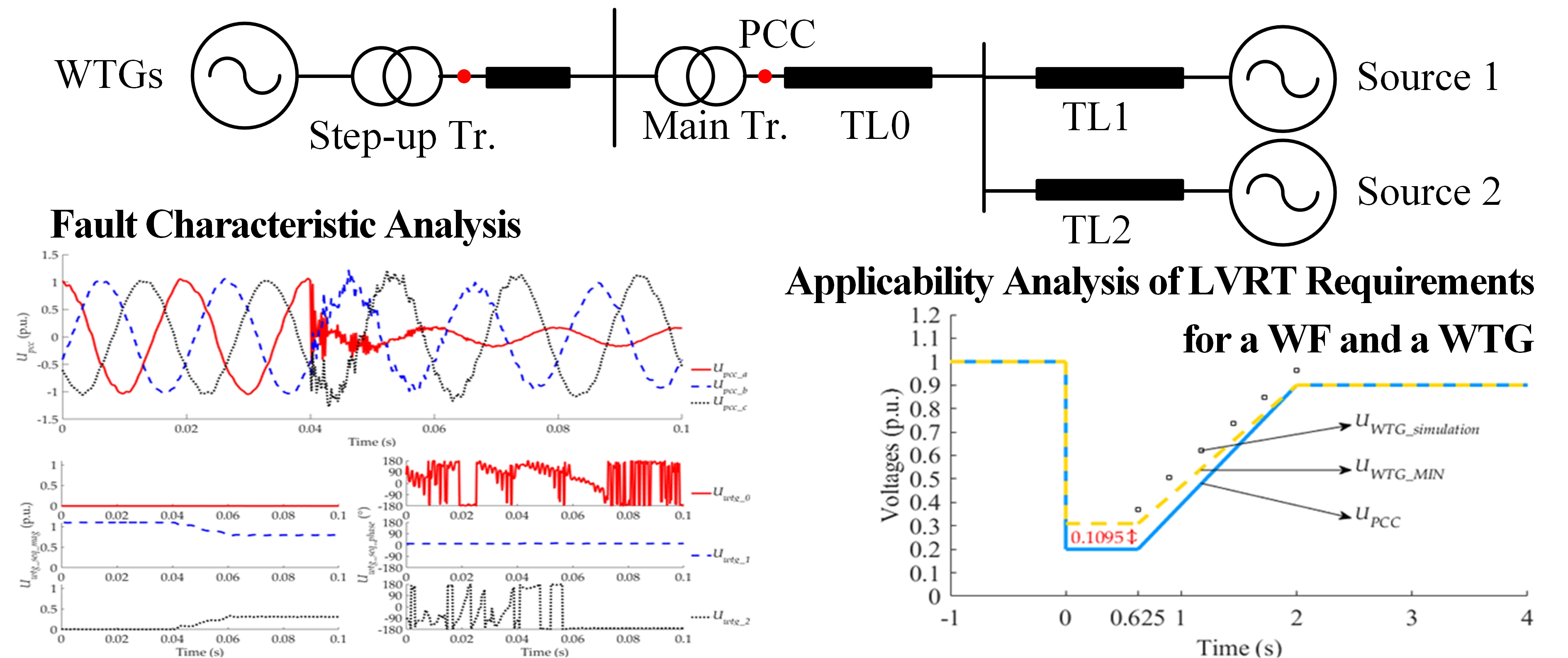
2.4. Back-to-Back Converter Modeling

The back-to-back converter model consists of the MSC, DC link capacitor with chopper protection, and the GSC. The MSC is connected to the PMSG directly. Ignoring the high frequency component, the model of the MSC based on d- and q-axis is the same as (4). The grid-voltage-oriented frame is adopted in the GSC, which means the d-axis orients to the grid voltage of phase A, and q-axis is 90° electrical angle ahead of d-axis. The direction of the grid side current is flowing into the GSC. The model of the GSC based on d- and q-axis is shown in (6).
e g d = ( L g s + r g ) i g d w g e L g i g q + u g d e g q = ( L g s + r g ) i g q + w g e L g i g d + u g q
where egd and egq are the grid side d- and q-axis voltages; rg and Lg are the line resistance and inductance between the GSC and grid side; igd and igq are the grid side d- and q-axis currents; wge is the grid angular frequency; ugd and ugq are the GSC d- and q-axis control voltages.

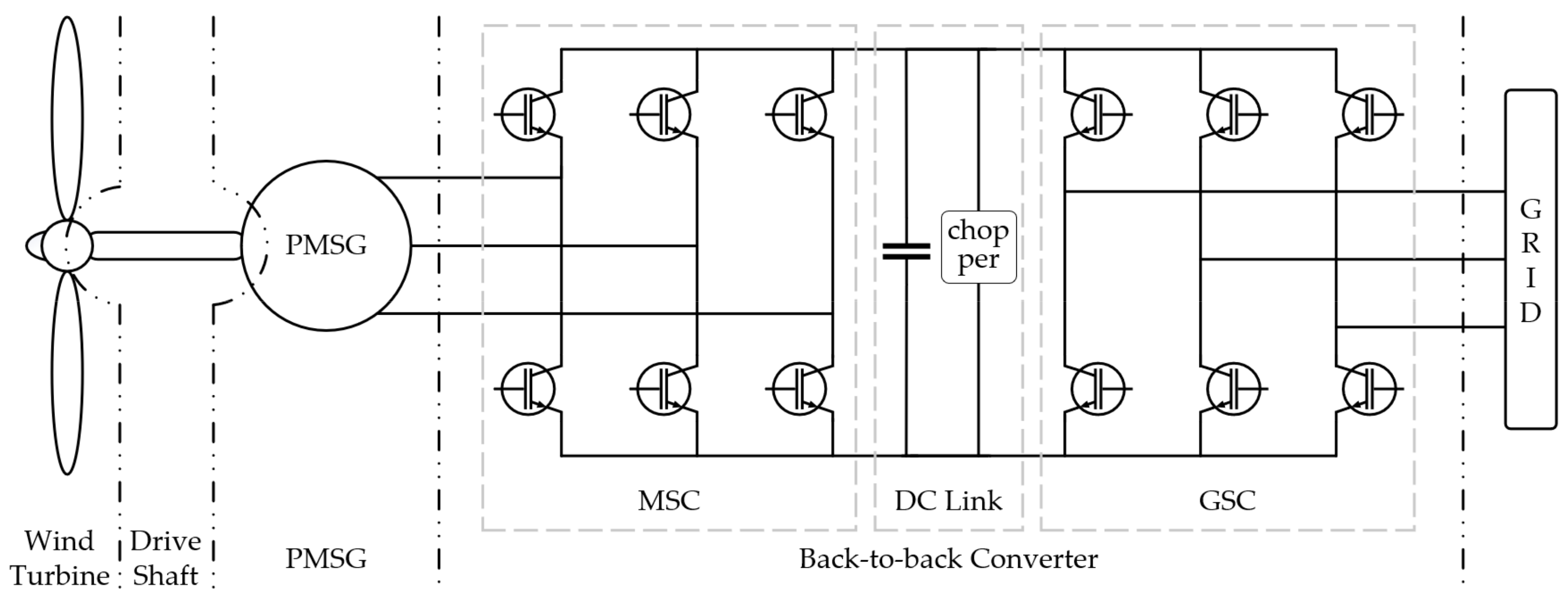
3. Control Strategy of a PMSG-Based WTG

The control structure diagram of the a PMSG-based WTG is shown in Figure 2. The control can be divided into three stages: no grid connection below cut-in wind speed or above cut-out wind speed, the maximum power point tracking (MPPT) control at low wind speed, and the rated power control at high wind speed. It is implemented mainly by electromagnetic torque control, and rotor angular velocity control [24,25,26,27,28]. The detailed control strategies of the MSC, GSC, and pitch angle are presented in Section 3.1, Section 3.2 and Section 3.3.
For any wind speed, there is an optimal angular velocity ωopt, correspondingly. The maximum generated power (Popt), which is also called as the optimum power, is given in (7).
P o p t = 1 2 ρ S r ω λ o p t 3 C p m a x = k o p t ω o p t 3
where Cpmax is the maximum wind power coefficient and kopt is the optimal power curve coefficient, as shown in (8).
k o p t = 1 2 ρ S r λ o p t 3 C p m a x
Therefore, the optimum torque Topt is shown in (9).
T o p t = k o p t ω o p t 3
As introduced in [26,27,28], the electromagnetic torque reference (Te*) and the angular velocity reference (wr*) are shown in (10) and (11).
T e * = k o p t ω r 2 , T e * = T e m a x = k o p t ω r m a x 2 T e T e max .
ω r * = ω r m a x ω r ω r m a x
where Temax and ωrmax are the maximal electromagnetic torque and the maximal rotor angular velocity, respectively.

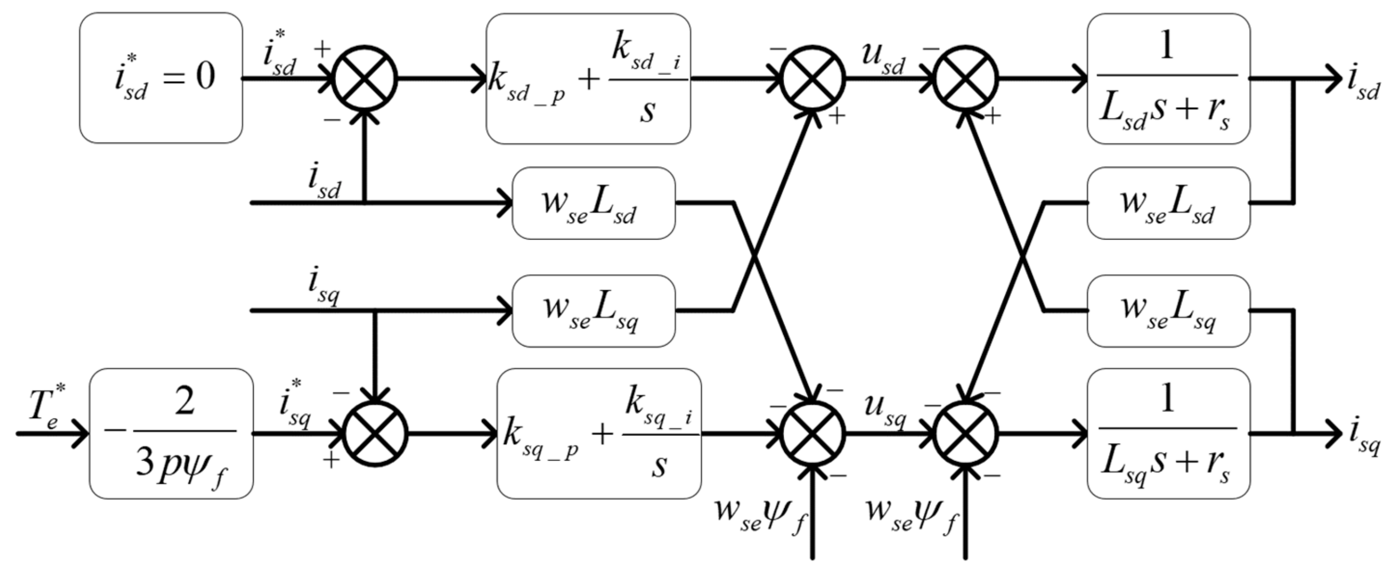
3.1. The Control Strategy of MSC

MSC adopts the vector control of rotor flux orientation based on feedforward decoupling to realize the control of the electromagnetic torque (Te).
The control block diagram of the MSC is shown in Figure 3. The d-axis current reference, isd*, is set to zero to guarantee that Te is only linearly related to the q-axis current (isq) [29,30]. In Figure 3, ksd_p and ksd_i are the proportional and integral coefficients of machine side d-axis current inner loop PI controller; ksq_p and ksq_i are the proportional and integral coefficients of machine side q-axis current inner loop PI controller; isd* and isq* are machine side d- and q-axis current references.

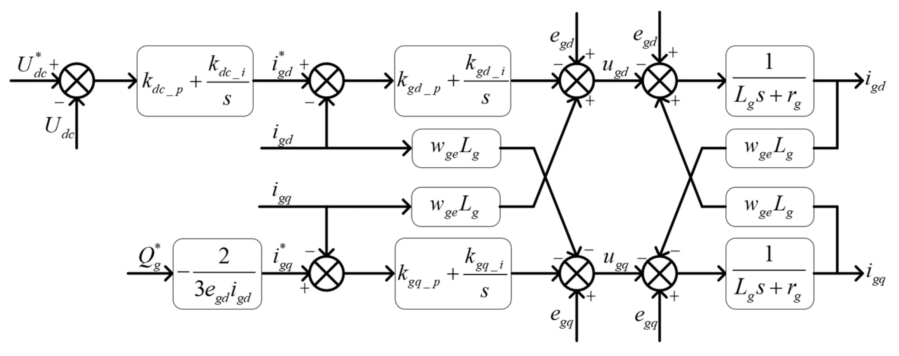
3.2. The Control Strategy of GSC

GSC adopts the vector control of grid voltage orientation based on feedforward decoupling to maintain the DC voltage stable and control reactive power from the grid.
The control block diagram of GSC is shown in Figure 4. The d-axis current reference (igd*) comes from the DC-link voltage outer loop PI controller. The q-axis current reference (igq) comes from the reactive power outer controller, in which Qg* is proportional to igq* because of the vector control of grid voltage orientation [29,30]. In this paper, Qg* is set to zero because the WTG or WF usually generates the active power as much as possible rather than the reactive power. When the grid has extra reactive power supply requirement, Qg* will be set to the specific value, which can be calculated from the required reactive power.
In Figure 4, kdc_p and kdc_i are the proportional and integral coefficients of grid side d-axis voltage outer loop PI controller; Udc and Udc* are the DC-link voltage and its reference; Qg and Qg* are the reactive power absorbed from the grid and its reference; kgd_p and kgd_i are the proportional and integral coefficients of the grid side d-axis current inner loop PI controller; kgq_p and kgq_i are the proportional and integral coefficients of the grid side q-axis current inner loop PI controller; igd* and igq* are the grid side d- and q-axis current references. The utility gird phase angle used in the GSC control comes from soft phase locked loop [31].

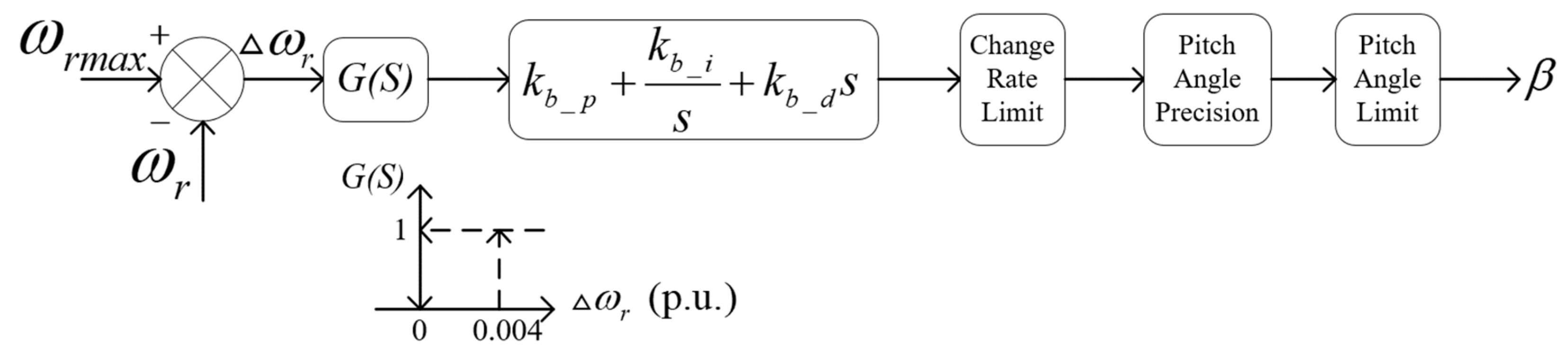
3.3. The Control Strategy of Pitch Angle

The pitch control, which only be activated in high speed, is to limit the rotor angular velocity ωr not to exceed the rated ωrmax. The control block diagram of pitch angle is shown in Figure 5 [24,32], where △ω is the difference between the rotor angular velocity reference and its actual value, kb_p, kb_i, and kb_d are the proportional, integral, and differential coefficients of the pitch angle controller.

4. The Relay Protections of a PMSG-Based WTG

To analyze the fault characteristic of the WTG and the WF as comprehensively as possible, the effects of relay protections should be taken into account. When the voltages of the PCC suddenly drops due to a certain grid fault, the individual WTG and the WF need to satisfy LVRT requirements, especially the minimal grid-connection time and the reactive current supply. Moreover, the controls of the WTG and the WF have very close relation with the LVRT requirements. Thus, the LVRT requirements can affect the fault characteristics of a WTG and a WF. Since the transient characteristics of a WTG or a WF are significantly affected by the protection methods adopted, the activations of the chopper protection and overcurrent protection are covered.
The LVRT requirement is described in the Section 4.1; the chopper protection and overcurrent protection in converters are respectively described in the Section 4.2 and Section 4.3.

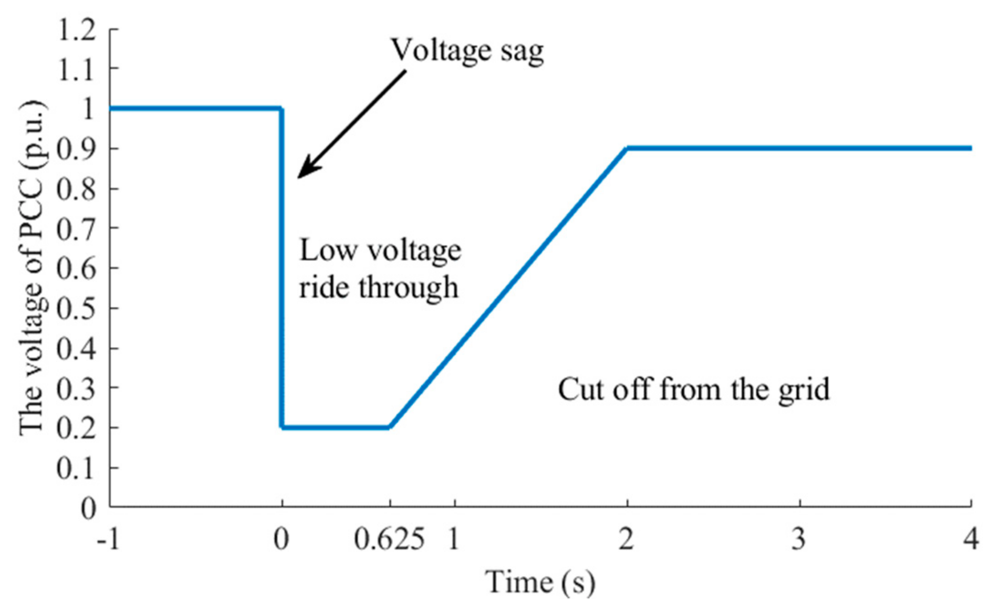
4.1. Low Voltage Ride-Through Requirement

When faults or disturbances cause the voltage sag at the PCC of a WF, the WF can only be disconnected from the grid after a certain time depending on the severity of voltage sag. In addition, if the WF is disconnected from the grid, both the MSC and GSC are blocked by the control signals in order to prevent potential overcurrent. According to the Chinese National Standard GB/T 1963–2011 [20], the required curve of low voltage ride-through for a WF is shown in Figure 6.
The choice of the assessment voltage at the PCC of a WF depends on the fault type, which is shown in Table 1. When a 3P, DLG, or LL fault occurs, the line voltages will be considered. Meanwhile, when a SLG fault occurs, the phase voltages instead of line voltages will be considered.
In addition, according to GB/T 1963-2011 [20], when a 3P fault occurs, a WF should have the ability of dynamic reactive power support, which requires a WF to inject dynamic reactive current as (12).
I P C C _ Q 1.5 × ( 0.9 U P C C ) I P C C _ N , ( 0.2 U P C C 0.9 )
where IPCC_Q is the required dynamic reactive current of a WF; UPCC is the voltage of the PCC of a WF; IPCC_N is the rated current of a WF. All the above quantities adopt per-unit values.

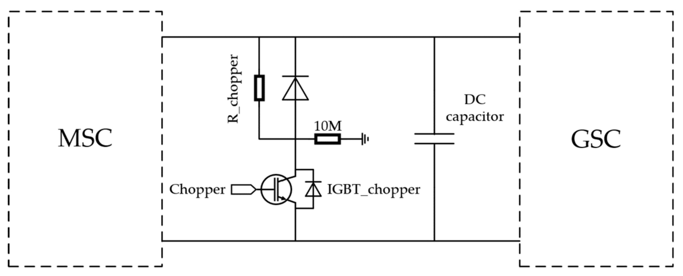
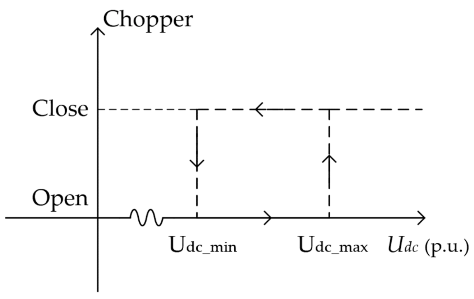
4.2. Chopper Protection

When a fault or disturbance causes the voltage sag, because the input power of the converter system is greater than the output power, the voltage of the DC link will rise, which may cause the breakdown of the DC capacitor and connected converter systems. With the paralleled DC unloading circuit, by switching the chopper resistance, R_chopper, the chopper protection can consume excess power to maintain the DC voltage, also to protect the DC capacitor. The chopper protection diagram is shown in Figure 7 [28,30]. The chopper protection usually adopts hysteresis control strategy which is shown in Figure 8. In this paper, Udc_min and Udc_max are set to be 1.025 p.u. and 1.075 p.u., respectively.

4.3. Overcurrent Protection in Converters

The overcurrent protection is used in both MSC and GSC to protect power electronic devices. If the current of the MSC or GSC is too high, it can shut down the converter. In this paper, the thresholds of both MSC and GSC overcurrent relays are set to 3.0 p.u.

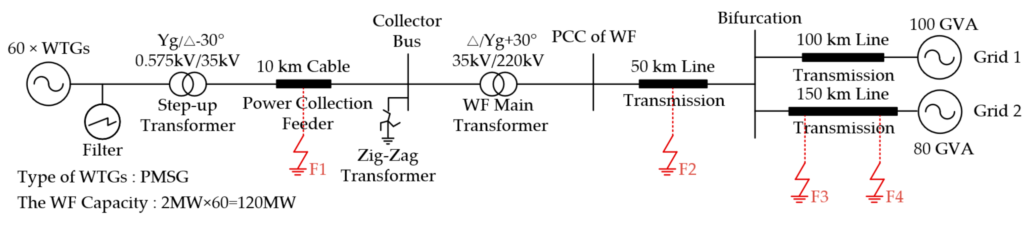
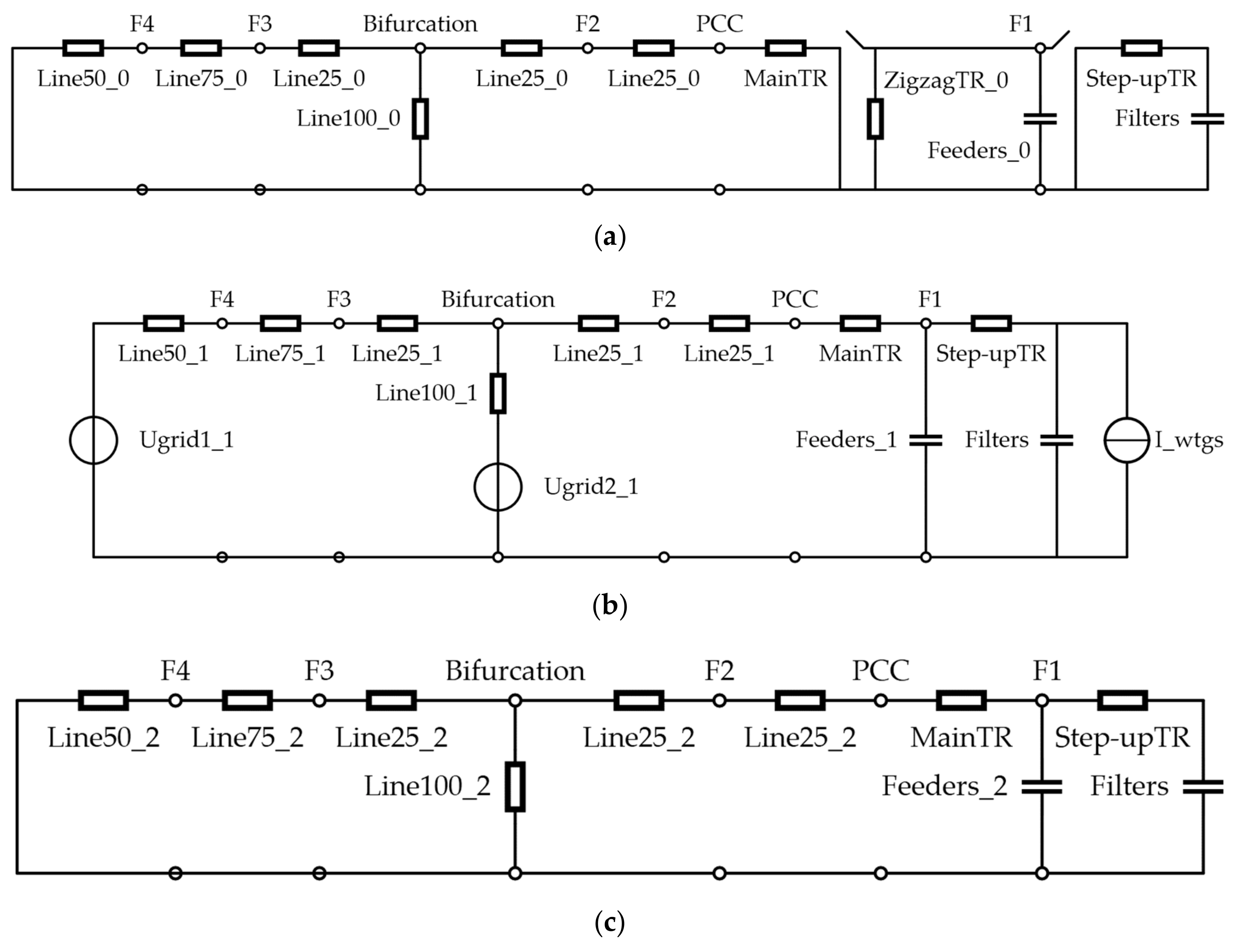
5. The Model System of a PMSG-based WF

To verify the performance of a PMSG-based WF model and analyze the fault characteristic of the WF, the detailed WTG model and an aggregated WF are built with an EMTP-RV simulator, which is a professional software widely adopted in the field of electromagnetic transient analysis. The detailed WTG model and related control strategies have been described in the previous sections. Methods on how to aggregate a whole WF is introduced in [33].
Figure 9 shows a model of a 120 MW aggregated WF studied in this paper, which contains six power collection feeders and sixty WTGs. Each power collection feeder (35 kV) is 10 kilometers long with ten WTGs interconnected equidistantly through step-up transformers. These power collection feeders are collected to a collector bus, which is connected to the strong grid (220 kV) through a main transformer. The strong grid (220 kV) consists of transmission lines and two equivalent power sources, the short circuit capacities of which are 100 GVA and 80 GVA, respectively. All WTGs are variable speed PMSGs. The filter devices adjoining WTGs can generate 0.135 p.u. reactive power under the rated voltage. The Zig-Zag transformer is collected to the collector bus to provide the zero potential to the 35 kV power collection system.
The characteristic of fault current depends on the winding connection of the step-up transformer and the main transformer. A grounded-wye-delta transformer is used as a step-up transformer in the aggregated WTG. This is because delta connection can provide isolation of the WTG from the zero-sequence behavior of the power collection feeder and the grounded-wye connection can provide a solid ground for the low-voltage side of the WTG [34]. A delta-grounded-wye transformer is mostly used as a main transformer and is modeled in this paper.
In addition, the impedance of the step-up transformer must be carefully designed to avoid possible resonance to the harmonic current or the excessive short-circuit current generated in the WTG. Typically, the multi-megawatt step-up transformer has a lumped series reactance of 0.06 p.u. and resistance of 0.01 p.u. [35,36], at least. Similarly, the main transformer is an important component of a large WF because of its substantial impedance. The dedicated main transformer has a lumped series reactance of 0.10 p.u. and resistance of 0.05 p.u. [35,36], at least.
The signs F1–F4 illustrated in Figure 9 show the fault positions. F1 depicts a feeder fault in the WF. F2 depicts a fault in the transmission line of the WF, which is 25 km away from the bifurcation. F3 and F4 depict grid faults which occurs at the transmission line connecting 80 GVA equivalent power source, which are respectively 25 km and 100 km away from the bifurcation. The parameters of the cable and the transmission line are shown in Table 2.
Assuming that the short-circuit impedance of two grids, the excitation branch of transformers, the shunt impedance of transmission lines and the series impedance of feeder cables are ignored, the zero-sequence, positive-sequence, and negative-sequence network of the interconnected power grid system are shown in Figure 10, where _0, _1, _2 represent the zero-sequence, positive-sequence, and negative-sequence component, respectively. The number behind line illustrate the length. Thus, WTGs can be regarded as a positive-sequence current source, filters can be regarded as a fixed value capacitor, zig-zag transformer only provides the access for the zero-sequence component.

6. Case Studies

In this section, the fault characteristic analysis of a PMSG-based WF are presented under various fault conditions varying the fault position, the fault type, and the wind speed, as shown in Table 3.
All faults occur at 0.04 s. For electromagnetic transient analysis, the wind speed can be assumed to be constant during the short time interval. The LVRT protection is implemented at the WTG terminal.

6.1. Faults with Different Position

In this subsection, different fault positions i.e., F1 (Case 1), F2 (Case 2), F3 (Case 3), and F4 (Case 4), with the same fault type (SLG fault at phase A) and wind speed (the rated) are considered. F1 fault occurs in the WF, whilst the other three faults occur at the gird side. Different fault positions can make the impedance from the PCC to the fault point different and consequently causes different voltage drop and current at the PCC, which may affect the fault characteristics. The results are shown in Figure 11, Figure 12, Figure 13 and Figure 14, respectively. All Figures a show the voltages at the PCC, including the instantaneous values (upper curves), magnitudes of the zero-, positive-, and negative-sequence values (bottom left curves), and phase angles of the zero-, positive-, and negative-sequence values (bottom right curves). All Figures b, c, and d respectively show the corresponding quantities of the currents at the PCC, the voltages at the WTG terminal, and the currents at the WTG terminal. All Figures e show the operations of chopper protection, overcurrent protection of both the MSC and the GSC, and the LVRT protection, respectively. The description about the sub-figures in Section 6.2 and Section 6.3 is the same.
Cases 1 depicts the fault which occurs in the power collection system, as shown in Figure 11. The voltage of the faulted phase at the fault position sags to nearly zero, meanwhile the voltages of the healthy phases increase to nearly square root of three times prior to the fault. However, the voltages at both PCC and WTG terminal do not drop dramatically due to the impedances and delta-connection of the main transformer and step-up transformer, as seen in Figure 11a,c.
In terms of zero-sequence component, the phase angles of the zero-sequence voltages and currents at both the WTG terminal and the PCC prior to the fault are jumbled, because the magnitudes of these components in the non-fault condition are very small. It can also be seen in the results of corresponding negative-sequence components. When the fault occurs, the zero-sequence components cannot reach to both the PCC and the WTG terminal due to the delta-connection of transformers, and the zero-sequence current only flows among the feeder and the zig-zag transformer, as shown in Figure 11a–d. In terms of positive-sequence component, the magnitude and phase angle of PCC currents have visible change due to the fault current flowing from the grid to the power collection system. In terms of the negative-sequence component, although the negative-sequence voltage at the WTG terminal is higher than that at the PCC, due to the high negative-sequence impedance from the feeder to the WTG terminal, the negative-sequence current at the WTG terminal is much lower than that at the PCC, as shown in Figure 11c,d. In addition, since the output power of the GSC is smaller than the input power of the MSC, the chopper protection is actuated due to the increasing voltage of the DC link, as shown in Figure 11e. The overcurrent protection of both the MSC and the GSC, and the LVRT protection are not activated.
Cases 2–4 depict the fault occurring outside the WF with different positions. The fault characteristics of these three cases are similar, as shown in Figure 12, Figure 13 and Figure 14. Since the SLG fault occurs at the grounded-wye connection side of the main transformer, the voltage of the faulted phase sags to nearly zero, and the voltages of the healthy phases remain almost stable as before.
In terms of the zero-sequence component, based on Figure 10a, the closer the fault position is to the PCC, the less the equivalent impedance from the PCC to the fault position is. Thus, the magnitude of the zero-sequence voltage of the PCC in Case 2 is larger than those in Cases 3 and 4. Meanwhile, since the impedance angle of the main transformer is similar as that of the line, the phase angles in three cases are almost the same, as seen in Figure 12a, Figure 13a and Figure 14a. The comparation about the magnitude and phase angle of zero-sequence current in three cases are the same with the analysis about the zero-sequence voltage, as seen in Figure 12b, Figure 13b and Figure 14b. However, due to the configuration of the main transformer, the zero-sequence component cannot reach to the WTG terminal, as shown in Figure 10a, Figure 12c,d, Figure 13c,d and Figure 14c,d. In terms of positive-sequence component, based on Figure 10b, the closer the fault position is to the PCC, the lower positive-sequence voltages of both the PCC and the WTG terminal are. Especially, when a remote fault (F4 fault) occurs, the positive-sequence voltage and current of WTG terminal almost remain stable. In terms of negative-sequence component, based on Figure 10c, the closer the fault position is to the PCC, the higher negative-sequence voltage of PCC is. Since the negative-sequence impedance is considerable large, all negative-sequence voltages and currents are small. In addition, similar with the analysis of Case 1, since the output power of the GSC is smaller than the input power of the MSC, the chopper protections in Cases 2–4 are actuated. What’s more, the severer the voltage sags, the worse the power unbalance is between the MSC and GSC, the more frequently the chopper protection actuates, as shown in Figure 12e, Figure 13e and Figure 14e.
In summary, the characteristics of a WF under an inside or outside fault scenario are different, mainly due to the connection of step-up transformers and main transformer. Compared faults all occurring outside of the WF but with different fault distance, the fault characteristics of a WTG are similar since the impedance of the main transformer is large.

6.2. Faults with Different Type

In this subsection, different fault types (i.e., SLG (Case 4), LL (Case 5), and 3P (Case 6) faults, with the same fault position (F4) and wind speed (the rated)) are considered. The results of Case 4 have been shown and analyzed in the previous section. The results of Cases 5 and 6 are shown in Figure 15 and Figure 16, respectively. In addition, WTGs carry out the dynamic reactive current support in the GSC according to (12).
When an LL or a 3P fault occurs, there is no zero-sequence component, as shown in Figure 15 and Figure 16. Compared to the magnitudes of the positive-sequence voltage at both the PCC and the WTG terminal in three cases as seen in Figure 14a,c, Figure 15a,c and Figure 16a,c, the voltage sags in Case 6 is the most serious, because the 3P fault is the most serious fault. The positive-sequence component directly related to the active power. Thus, the lower positive-sequence voltage of the PCC and the WTG terminal is, the less power the WTG generates. Consequently, the worse the power unbalance between the MSC and the GSC is, the more frequently the chopper protection actuates, as shown in Figure 14e, Figure 15e and Figure 16e. In terms of the negative-sequence component, there is no negative-sequence components existing in Case 6. The negative-sequence voltages at both the PCC and the WTG terminal in Case 5 are higher than those in Case 4, as seen in Figure 14a and Figure 15a, Figure 14c and Figure 15c. Thus, the magnitude and phase distortions of voltage at the WTG terminal are more obvious in Case 5, as compared Figure 14c and Figure 15c, Figure 14d and Figure 15d. These distortions are not induced by any zero-sequence component, since all zero-sequence component are blocked by the delta-connection of the main transformer. Thus, the effect of the negative-sequence voltages at the PCC and WTG terminal cannot be ignored. In addition, because the negative-sequence circuit impedance is considerable large, the negative-sequence current is still low, as shown in Figure 15b,d.
In summary, when an SLG fault occurs, the zero-sequence components mainly affect the fault characteristics of both a WF and a WTG; in the case of an LL fault, the negative-sequence components mainly affect the fault characteristics of both a WF and a WTG; in the case of a 3P fault, the severe positive-sequence voltage sag activates the chopper protection frequently.

6.3. Faults with Different Wind Speeds

In this subsection, different wind speeds (i.e., the rated (Case 4), high (Case 7), and low (Case 8) wind speeds, with the same fault type (SLG fault at phase A) and fault position (F4)) are considered. The results of Case 4 have been shown and analyzed in the previous section. The results of Cases 7 and 8 are shown in Figure 17 and Figure 18, respectively. The reason why different wind speeds are taken into account is that the rotation speed of the rotor and output power of the WTG depend on the wind speed, which may consequently affect the fault characteristics.
Compared the results shown in Figure 14, Figure 17 and Figure 18, the fault characteristics of a WTG and the WF are almost the same. The rotation speed of the rotor in Case 8 is smaller than those in Cases 4 and 7, since the WTG in Case 8 works at the MPPT mode whilst the WTGs in Cases 4 and 7 work at the rated power generation mode. However, these differences do not visibly affect the fault characteristic of a WTG, as compared the results shown in Figure 14, Figure 17 and Figure 18. The reason is that the networks at the MSC and GSC sides are clearly separated by the DC link. In addition, since the inertia of the rotor is usually large, the rotation speed of the rotor can only slightly increase.
It is worth mentioning that the chopper protection in Case 8 is not activated, which is different from those in Cases 4 and 7, as shown in Figure 14e, Figure 17e and Figure 18e. When the wind speed is low, the power passing through the MSC and GSC prior to a fault inception is small. Consequently, the power unbalance after a fault inception is not serious, compared with that in rated or high wind scenarios. The voltage of DC link can be easily controlled by the GSC, which causes the chopper protection inactivated.

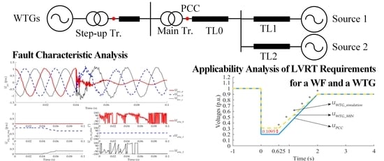
7. Applicability Analysis of Low Voltage Ride-Through Requirements for a Whole WF and an Individual WTG

As a higher penetration level of wind power is going to be reached in the power system, the possible negative effects of wind generation will no longer be neglected, such as voltage flicker, loss of generation for frequency support, voltage and power variation due to the variable speed of the wind, and the risk of instability due to lower degree of controllability [37]. To eliminate the potential adverse impacts, many countries have issued the related gird codes or rules for wind power interconnection. One of the significant requirements is LVRT ability.
In 2012, China issued the PRC National Standard [20], in which the LVRT requirements for a WF were proposed. Then, in 2018, the LVRT requirements, which an individual WTG must satisfy, were proposed in another new PRC National Standard [21]. Comparing these two standards, the former aims at a whole WF, whilst the latter aims at an individual WTG. However, these two standards have the exact same requirements for LVRT, including the minimal grid-connection time, minimal reactive current support ability, active power recovery time, and so on. The reason is that the voltage sag at the WTG terminal and that at the PCC of a WF are assumed to be identical. However, this assumption is debatable, especially in the case of a large WF. The following subsection will analysis the applicability of LVRT requirements for a whole WF and an individual WTG, from the point of minimal grid-connection time and minimal reactive current support ability.

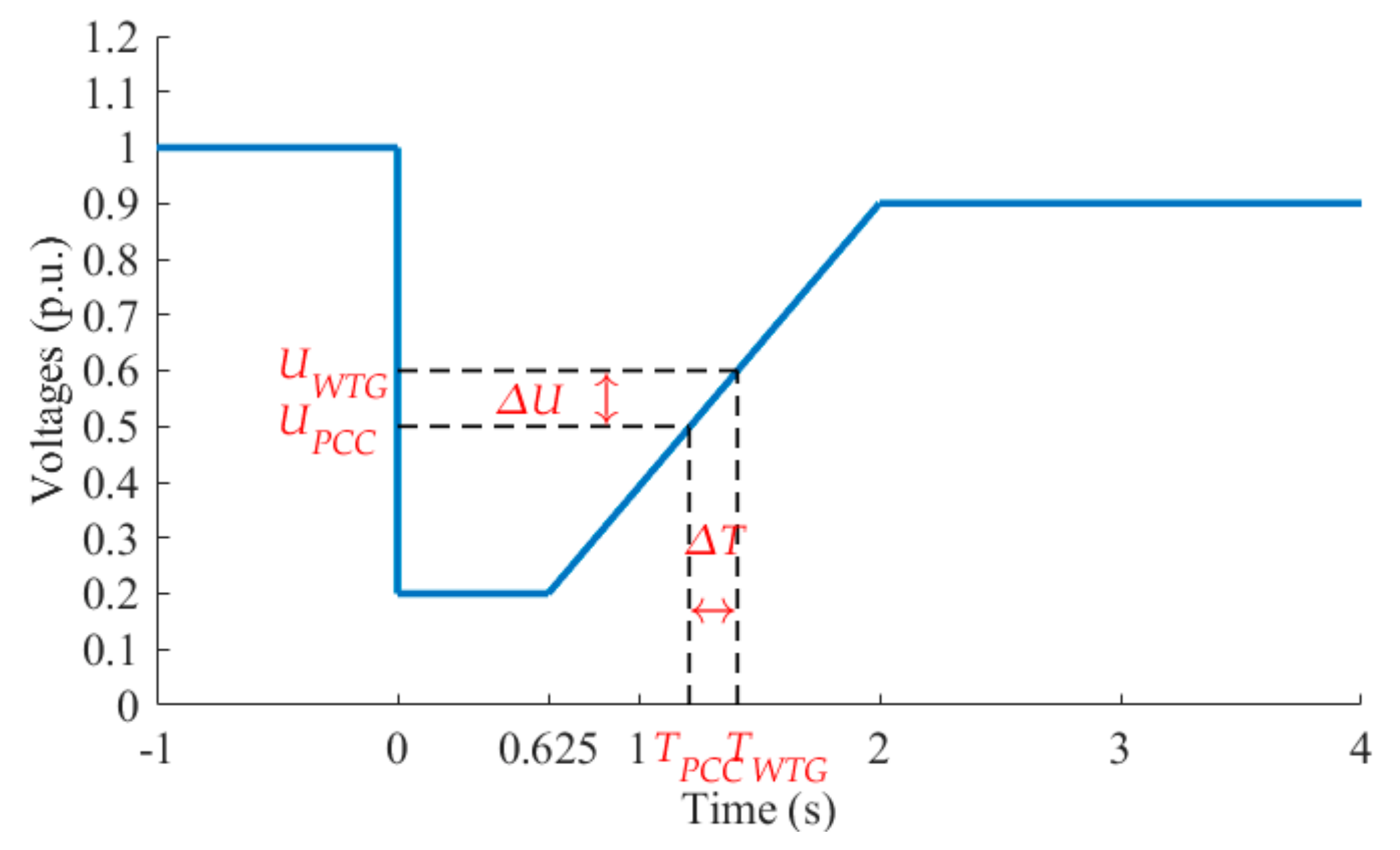
7.1. Discussion on the Minimal Grid-Connection Time

For asymmetrical faults, the voltage sag condition experienced at a WTG terminal can be substantially different from the PCC of a WF due to the configurations of transformers, including the step-up transformer and main transformer. For symmetrical faults, although the transformers’ configurations do not affect the voltage sag conditions, the voltage difference (△U) between the voltage (UWTG) at WTG terminal and the voltage (UPCC) at PCC is non-ignorable, due to voltage drops generated at the step-up transformer, power collection feeder, and main transformer [38,39]. Considering the currents flowing from WTGs and reactive power compensation devices to PCC and impedances of step-up transformers, feeders, and main transformers, UWTG is usually higher than UPCC, as in (13).
U W T G = U P C C + Δ U
In case that a grid fault occurs, UWTG and UPCC drop together. From the point of the WF, the grid-connection time should be longer than TPCC. However, from the point of the WTG, since the WTG can only “see” UWTG but not UPCC, the WTG has to keep connection with the gird for TWTG according to the same requirements in [20] and [21], as shown in Figure 19. The relationship between TWTG and TPCC can be concluded in (14).
T W T G = T P C C + Δ T
where △T is the time difference between TWTG and TPCC. Obviously, TWTG is larger than TPCC, which means that the requirements in [21] are harsher than those in [20] from the point of a WTG. Consequently, it would be helpful to WTG manufacturers and WF administrators to clarify how harsh the new National Standard [21] is. In other words, the series minimal △U when UPCC is in 0.2, 0.9 under all kinds of WF configuration and should be calculated and analyzed.
Assuming that the series impedance of power collection feeders is ignored, which is reasonable because this impedance is much less than that of main transformer. The impedance of the step-up transformer is also neglected, since the voltage detected in [21] is the voltage at the high voltage side of the step-up transformer, which means that the WTG and its step-up transformer are seen as one unit. Thus, the simplified WF configuration could be shown in Figure 20a. ZTR = RTR + jXTR represents the impedance of the main transformer. X . represents the phasor quantity of X, while X represents the corresponding magnitude. U . PCC is the voltage of the PCC, and I . PCC is the current flowing out of the PCC.
It bears mentioning that the reactive power compensation devices, which could be capacitor banks, static var compensators (SVCs), or static synchronous compensators (STATCOMs), and the capacitance component of the power collection feeders, are also ignored in this equivalent circuit. Since we do not know what kind of reactive power compensation device is used in certain WFs, it is difficult to calculate the minimal △U, which is the lowest value in all WF with all possible configurations, under the consideration of reactive power compensation devices. Moreover, the reactive power compensation devices are usually connected with the power collection feeder or bus, and the reactive current flowing out would pass through the main transformer. This will increase △U and UWTG and consequently make the difference, which should be considered in [20] and [21].
Assuming U . PCC as the reference phasor quantity, which means U . PCC = UPCC∠0°, the phasor diagram is shown in Figure 20b. φ is the phase angle that U . PCC leads I . PCC and belongs to (0°, 90°) since the WF will generate active and reactive power; δ is the phase angle that U . PCC leads U . WTG; θ is impedance angle of ZTR, i.e., θ = arctan (XTR/RTR); I . PCC_P and I . PCC_Q are the active and reactive component of I . PCC. It is easily known that δ = φθ, which can be either positive when U . PCC leads U . WTG or negative when U . WTG leads U . PCC.
The relation among UWTG, UPCC, IPCC and ZTR can be concluded as:
U W T G 2 = U P C C 2 + I P C C 2 Z T R 2 + 2 U P C C I P C C Z T R cos φ θ = U P C C 2 + I P C C _ Q sin φ 2 Z T R 2 + 2 U P C C I P C C _ Q cos φ sin φ Z T R cos θ + 2 U P C C I P C C _ Q Z T R sin θ = U P C C 2 + f ( I P C C _ Q , φ ) φ ( 0 ° , 90 ° ]
where f(IPCC_Q, φ) is a new function relating to IPCC_Q and φ. In addition, since δ could be either positive or negative, (15) is correct when U . PCC leads or lags U . WTG. To calculate the minimal UWTG, f(IPCC_Q, φ) should be analyzed as:
f ( I P C C _ Q , φ )   I P C C _ Q > 0 f ( I P C C _ Q , φ )   φ = 2 I P C C _ Q Z T R sin φ 2 I P C C _ Q Z T R cot φ + U P C C cos θ < 0
Obviously, for any particular φ, the lower IPCC_Q is, the lower f(IPCC_Q, φ) is. In addition, for any particular IPCC_Q, the higher φ is, the lower f(IPCC_Q, φ) is. Thus, only when IPCC_Q and φ are respectively minimum and maximum, which are respectively value satisfying (12) and 90°, f(IPCC_Q, φ) is the minimum. Consequently, both UWTG and △U are minimum. It is worth mentioning that in this condition, the WF only supplies minimal reactive power and does not supply active power to the grid, which is very common operation mode when a grid fault occurs.
As a result, the minimal voltage magnitude of the WTG terminal (UWTG_MIN) is shown in (17), where IPCC_N is regard as 1.0 p.u. in (12).
U W T G _ M I N = U P C C 2 + 1.5 × ( 0.9 U P C C ) 2 Z T R 2 + 2 U P C C 1.5 × ( 0.9 U P C C ) Z T R sin θ .
Thus, the LVRT curve suggested under the consideration of △U and that in the Standard are respectively shown with dashed and solid curves in Figure 21. From Figure 21, when the voltage of PCC drops from 1.0 p.u. to UPCC, the voltage of WTG terminal only drops to UWTG_MIN, which is the lowest value in all WFs with all possible configurations and parameters. Given the impedance of power collection feeders and step-up transformers, the reactive current support from reactive power compensation devices and cables, and the possible existing active current of the WF, are all ignored.
When the voltage of PCC drops to 0.2 p.u., the UWTG_MIN only drops to 0.3095 p.u., which is calculated by solving (17). The meaning of this study is that, if the voltage of a WTG terminal drops to a value under 0.3095 p.u., all WTGs can be disconnected from the gird immediately, since in this case the voltage of PCC has dropped to a certain value under 0.2 p.u., no matter what the configuration of the WF is. Moreover, if the components previously ignored are also taken into account, the voltage of the WTG terminal could be much higher than UWTG_MIN, which can be seen as the UWTG_simulation simulated with various UPCC. These are based on a normal WF with general configuration and parameters and are shown with a “□” in Figure 21.

7.2. Discussion on the Minimal Reactive Current Support Ability

On the other hand, the reactive current supply requirements in [20] and [21] also need to be re-examined. As required in [20], when a 3P fault occurs, a WF should have the ability of dynamic reactive power support, which requires a WF to inject dynamic reactive current, as in (12). Meanwhile, it is required in [21] that all WTGs should support reactive current as (18), where UPCC in (12) is replaced by UWTG.
I W T G _ Q 1.5 × ( 0.9 U W T G ) I N _ W T G , ( 0.2 U W T G 0.9 )
where IWTG_Q and IN_WTG are the dynamic reactive current and the rated current of a WTG, respectively. All the above quantities adopt per-unit values.
However, considering the actual phase angle δ between U . PCC and U . WTG, the actual dynamic reactive current at the PCC (I’PCC_Q) is shown as (19).
I P C C _ Q 1.5 × ( 0.9 U W T G ) I N _ W T G cos δ , ( 0.2 U W T G 0.9 )
It is obvious that IPCC_Q is much smaller than IPCC_Q, since UWTG is usually larger than UPCC. The actual reactive current (dashed line in left part of Figure 22) supported by the whole WF when all WTGs support reactive currents as required in [21], is smaller than the reactive current (solid line in left part of Figure 22) required in [20]. The difference between these two reactive currents is 0.16425 p.u., when the UPCC drop to 0.2 p.u. On the other hand, the actual reactive power (dashed line in right part of Figure 22) supplied by the whole WF is insufficient, compared with the reactive power (dashed line in right part of Figure 22) required in [20], due to the same reason. The largest difference between the two reactive powers is 0.0464 p.u., which occurs when UPCC drops to 0.45 p.u., but not to 0.2 p.u.
Thus, it is requisite that the control center of a WF should compensate the reactive current by dispatch control to meet the grid code requirements in [20].

7.3. Summary of Applicability Analysis of LVRT Requirements

In summary, although it is important to require a WTG to satisfy some rules when connecting to the grid, the requirements should be carefully proposed. From the point of minimal grid-connection time, since the voltage of WTG terminal is usually higher than the voltage of PCC, the voltage sag problem seen by a WTG is less serious than that seen by a WF. Even when the voltage of PCC drops to 0.2 p.u., the voltage in the WTG terminal only drops to 0.3095 in all WFs with all possible configurations and parameters, no matter what the configuration the WF is, and what kind of reactive power compensation devices is used. In one word, the new requirement in [21] is harsher to WTG manufacturers or WF administrators, as presented in Section 7.1. On the contrary, from the point of minimal reactive current or power support, the new requirement in [21] is insufficient to meet the requirement in [20] for a whole WF. The WF need extra reactive power compensation devices to satisfy the LVRT requirement in [20]. The analysis in Section 7.2 could be useful for calculating the minimal capacity of the extra reactive power compensation devices.

8. Conclusions

This paper describes a detailed modeling of a PMSG-based WF and analyzes the fault characteristics of the WF with the consideration of different fault positions, fault types, and wind speeds. The fault characteristic analysis could be helpful for developing new control or protection methods for a PMSG-based WF.
In addition, applicability analysis of LVRT requirements for a WF and a WTG was implemented. Considering the voltage drop on the impedance of the main transformer and the current contributions from WTGs and reactive compensation devices in a WF, it is concluded that from the point of minimal grid-connection time, the new requirement for a WTG is harsher to WTG manufacturers or WF administrators. On the contrary, from the point of reactive current or power support, the new requirement for a WTG is insufficient to meet the requirement for a whole WF. This applicability analysis of LVRT requirements could serve as a reference for WTG manufacturers, WF administrators, and grid operators.

Author Contributions

All the authors contributed to publish this paper. T.Z. and W.C. proposed the scheme and carried out the simulation tests; T.Z., W.C. and J.H. revised the original scheme. Writing and final review were done by all the authors.

Funding

This work was funded by the Key Project of Smart Grid Technology and Equipment of National Key Research and Development Plan of China (2016YFB0900600), National Natural Science Foundation of China (Grant No. 51707173), Technology Projects of State Grid Corporation of China (52094017000W) and Science and Technology Projects of Inner Mongolia Power (Group) Co., Ltd. [2017] 46.

Conflicts of Interest

The authors declare no conflict of interest.

References

  1. Wikipedia, The Free Encyclopedia. Copenhagen Climate Council. Available online: https://en.wikipedia.org/.wiki/Copenhagen_Climate_Council (accessed on 17 June 2018).
  2. Singer, S.; Denruyter, J.P.; Yener, D. The Energy Report: 100% Renewable Energy by 2050. Available online: http://www.worldwildlife.org (accessed on 22 February 2017).
  3. Sawyer, S. Global Wind Power: 2017 Market and Outlook to 2022. Available online: https://gwec.net/global-wind-power-2017-market-and-outlook-to-2022/ (accessed on 1 June 2018).
  4. Zheng, T.Y.; Cha, S.T.; Kim, Y.H.; Crossley, P.A.; Lee, S.H.; Kang, Y.C. Design and Evaluation of a Protection Relay for a Wind Generator Based on the Positive- and Negative-Sequence Fault Components. J. Electr. Eng. Technol. 2013, 8, 1029–1039. [Google Scholar] [CrossRef] [Green Version]
  5. Hu, S.J.; Li, J.L.; Xu, H.H. Modeling on converter of direct-driven WECS and its characteristic during voltage sags. In Proceedings of the 2008 IEEE International Conference on Industrial Technology, Chengdu, China, 21–24 April 2008; pp. 1–5. [Google Scholar]
  6. Huang, Y.H.; Wang, J.; Feng, Z.; Yang, Z.P.; Zhang, B.Y.; Li, G. Research on short-circuit fault characteristics of direct-drive permanent magnet wind turbine. In Proceedings of the 2011 International Conference on Electrical and Control Engineering, Yichang, China, 16–18 September 2011; pp. 4911–4914. [Google Scholar]
  7. Abedini, A.; Nasiri, A. PMSG Wind Turbine Performance Analysis During Short Circuit Faults. In Proceedings of the 2007 IEEE Canada Electrical Power Conference, Montreal, QC, Canada, 25–26 October 2007; pp. 160–165. [Google Scholar]
  8. Yazdani, A.; Iravani, R. A Neutral-Point Clamped Converter System for Direct-Drive Variable-Speed Wind Power Unit. IEEE Trans. Energy Convers. 2006, 21, 596–607. [Google Scholar] [CrossRef]
  9. Muyeen, S.M.; Takahashi, R.; Murata, T.; Tamura, J.; Ali, M.H. Transient stability analysis of permanent magnet variable speed synchronous wind generator. In Proceedings of the 2007 International Conference on Electrical Machines and Systems (ICEMS), Seoul, Korea, 8–11 October 2007; pp. 288–293. [Google Scholar]
  10. Song, G.B.; Wang, X.B.; Chang, Z.X.; Tang, J.S.; Liu, P.Y. A novel protection method of collecting power lines in PMSG wind farm. In Proceedings of the 2016 IEEE PES Asia-Pacific Power and Energy Engineering Conference (APPEEC), Xi’an, China, 25–28 October 2016; pp. 2086–2090. [Google Scholar]
  11. Wang, C.; Liu, X.; Chen, Z. Incipient Stator Insulation Fault Detection of Permanent Magnet Synchronous Wind Generators Based on Hilbert–Huang Transformation. IEEE Trans. Magn. 2014, 50, 1–4. [Google Scholar] [CrossRef]
  12. Freire, N.M.A.; Estima, J.O.; Marques Cardoso, A.J. Open-Circuit Fault Diagnosis in PMSG Drives for Wind Turbine Applications. IEEE Trans. Ind. Electron. 2013, 60, 3957–3967. [Google Scholar] [CrossRef]
  13. Jlassi, I.; Estima, J.O.; Khojet El Khil, S.; Mrabet Bellaaj, N.; Marques Cardoso, A.J. Multiple Open-Circuit Faults Diagnosis in Back-to-Back Converters of PMSG Drives for Wind Turbine Systems. IEEE Trans. Power Electron. 2015, 30, 2689–2702. [Google Scholar] [CrossRef]
  14. Jlassi, I.; Cardoso, A.J.M. IGBTs and current sensors fault diagnosis in direct-drive PSMG wind turbine systems using adaptive thresholds. In Proceedings of the IECON 2017 43rd Annual Conference of the IEEE Industrial Electronics Society, Beijing, China, 29 October–1 November 2017; pp. 5072–5077. [Google Scholar]
  15. Hansen, A.D.; Michalke, G. Multi-pole permanent magnet synchronous generator wind turbines’ grid support capability in uninterrupted operation during grid faults. IET Renew. Power Gener. 2009, 3, 333–348. [Google Scholar] [CrossRef]
  16. Li, J.L.; Zhu, Y.; He, X.T.; Xu, H.H. Study on low voltage ride through characteristic of full power converter direct-drive wind power system. In Proceedings of the 2009 IEEE 6th International Power Electronics and Motion Control Conference, Wuhan, China, 17–20 May 2009; pp. 2213–2216. [Google Scholar]
  17. Nguyen, T.H.; Lee, D. Advanced Fault Ride-Through Technique for PMSG Wind Turbine Systems Using Line-Side Converter as STATCOM. IEEE Trans. Ind. Electron. 2013, 60, 2842–2850. [Google Scholar] [CrossRef]
  18. Erlich, I.; Bachmann, U. Grid code requirements concerning connection and operation of wind turbines in Germany. In Proceedings of the 2005 IEEE Power Engineering Society General Meeting, San Francisco, CA, USA, 12–16 June 2005; pp. 1253–1257. [Google Scholar]
  19. Iov, F.; Hansen, A.D.; Sørensen, P. Mapping of Grid Faults and Grid Codes; Tech. Rep. Risø-R-1617(EN); Risø National Laboratory, Technical University of Denmark: Roskilde, Denmark, 2007. [Google Scholar]
  20. Technical rule for connecting wind farm to power system, PRC National Standard GB/T 19963-2011, 2012. Available online: http://www.gb688.cn/bzgk/gb/newGbInfo?hcno=C0B59C55FD4B287CDF02842D074D1476 (accessed on 30 December 2011).
  21. Wind turbines—Test procedure of voltage fault ride through capability, PRC National Standard GB/T 36995-2018, 2019. Available online: http://www.gb688.cn/bzgk/gb/newGbInfo?hcno=A9D6F07EB8A70DEFA2974C513C6F3325 (accessed on 28 December 2018).
  22. Knudsen, T.; Bak, T.; Svenstrup, M. Survey of wind farm control-power and fatigue optimization. Wind Energy 2015, 18, 1333–1351. [Google Scholar] [CrossRef]
  23. Boersma, S.; Doekemeijer, B.M.; Gebraad, P.M.; Fleming, P.A.; Annoni, J.; Scholbrock, A.K.; van Wingerden, J.W. A tutorial on control-oriented modeling and control of wind farms. In Proceedings of the 2017 American Control Conference (ACC), Seattle, WA, USA, 24–26 May 2017; pp. 1–18. [Google Scholar]
  24. Abo-Khalil, A.G.; Lee, D.C. Dynamic modeling and control of wind turbines for grid-connected wind generation system. In Proceedings of the 2006 37th IEEE Power Electronics Specialists Conference, Jeju, Korea, 18–22 June 2006. [Google Scholar]
  25. Yan, G.G.; Wei, Z.C.; Mu, G. Dynamic Modeling and Control of Directly-driven Permanent Magnet Synchronous Generator Wind Turbine. In Proceedings of the 2009 Chinese Society of Universities for Electric Power System and its Automation, Nantong, China, 21–23 August 2009; Volume 21, pp. 34–39. [Google Scholar]
  26. Datta, R.; Ranganathan, V.T. A method of tracking the peak power points for a variable speed wind energy conversion system. IEEE Trans. Energy Conv. 2003, 18, 163–168. [Google Scholar] [CrossRef]
  27. Shen, B.; Mwinyiwiwa, B.; Zhang, Y.Z. Sensorless Maximum Power Point Tracking of Wind by DFIG Using Rotor Position Phase Lock Loop (PLL). IEEE Trans. Power Electron. 2009, 24, 942–951. [Google Scholar] [CrossRef]
  28. Zhao, R.D.; Wang, Y.J.; Zhang, J.S. Maximum Power Point Tracking Control of the Wind Energy Generation System with Direct-driven Permanent Magnet Synchronous Generators. J. Chin. Electr. Eng. Sci. 2009, 29, 106–111. [Google Scholar]
  29. Chinchilla, M.; Arnaltes, S.; Burgos, J.C. Control of permanent-magnet generators applied to variable-speed wind-energy systems connected to the grid. IEEE Trans. Energy Convers. 2006, 21, 130–135. [Google Scholar] [CrossRef]
  30. Haque, M.E.; Negnevitsky, M.; Muttaqi, K.M. A Novel Control Strategy for a Variable-Speed Wind Turbine with a Permanent-Magnet Synchronous Generator. IEEE Trans. Ind. Appl. 2010, 46, 331–339. [Google Scholar] [CrossRef]
  31. Chung, S.K. A phase tracking system for three phase utility interface inverters. IEEE Trans. Power Electron. 2000, 15, 431–438. [Google Scholar] [CrossRef]
  32. Conroy, J.F.; Watson, R. Low-voltage ride-through of a full converter wind turbine with permanent magnet generator. IET Renew. Power Gener. 2007, 1, 182–189. [Google Scholar] [CrossRef]
  33. Cai, X.; Li, Z. Dynamic Modeling of Wind Turbines and Wind Farms; Science Press: Beijing, China, 2006; pp. 240–243. ISBN 978-7-03-049126-8. [Google Scholar]
  34. Reichard, M.L.; Finney, D.; Garrity, J.T. Windfarm system protection using peer-to-peer communications. In Proceedings of the 2007 60th Annual Conference for Protective Relay Engineers, College Station, TX, USA, 27–29 March 2007. [Google Scholar]
  35. Hornak, D.; Chau, N.H.J. Green power—Wind generated protection and control considerations. In Proceedings of the 57th Annual Conference for Protective Relay Engineers, College Station, TX, USA, 1 April 2004; pp. 110–131. [Google Scholar]
  36. Causebrook, A.; Atkinson, D.J.; Jack, A.G. Fault Ride-Through of Large Wind Farms Using Series Dynamic Braking Resistors (March 2007). IEEE Trans. Power Syst. 2008, 22, 966–975. [Google Scholar] [CrossRef]
  37. Molinas, M.; Suul, J.A.; Undeland, T. Low Voltage Ride Through of Wind Farms with Cage Generators: STATCOM Versus SVC. IEEE Trans. Power Electron. 2008, 23, 1104–1117. [Google Scholar] [CrossRef]
  38. Mohseni, M.; Islam, S.; Masoum, M.A.S. Low voltage ride-through requirements at the PCC versus wind generator terminals. In Proceedings of the 2010 20th Australasian Universities Power Engineering Conference, Christchurch, New Zealand, 5–8 December 2010; pp. 1–6. [Google Scholar]
  39. Gomis-Bellmunt, O.; Junyent-FerrÉ, A.; Sumper, A.; Bergas-JanÉ, J. Ride-Through Control of a Doubly Fed Induction Generator Under Unbalanced Voltage Sags. IEEE Trans. Energy Convers. 2008, 23, 1036–1045. [Google Scholar] [CrossRef]
Figure 1. Model structure of a permanent magnet synchronous generator (PMSG)-based wind turbine generator (WTG). MSC: machine side converter; GSC: grid side converter; DC link: direct current link.
Energies 12 03400 g001
Figure 2. The control structure diagram of a PMSG-based WTG.
Energies 12 03400 g002
Figure 3. The control block diagram of the MSC.
Energies 12 03400 g003
Figure 4. The control block diagram of the GSC.
Energies 12 03400 g004
Figure 5. The control block diagram of pitch angle.
Energies 12 03400 g005
Figure 6. Low voltage ride-through requirement.
Energies 12 03400 g006
Figure 7. Configuration of chopper protection.
Energies 12 03400 g007
Figure 8. Chopper protection strategy.
Energies 12 03400 g008
Figure 9. PMSG-based WF model.
Energies 12 03400 g009
Figure 10. Sequence networks of the system. (a) Zero-sequence network; (b) positive-sequence network; and (c) negative-sequence network.
Energies 12 03400 g010
Figure 11. Results for Case 1. (a) Voltages of the point of common coupling (PCC); (b) currents of the PCC; (c) voltages of the WTG terminal; (d) currents of the WTG terminal; (e) protection signals.
Energies 12 03400 g011aEnergies 12 03400 g011bEnergies 12 03400 g011c
Figure 12. Results for Case 2. (a) Voltages of the PCC; (b) Currents of the PCC; (c) Voltages of the WTG terminal; (d) Currents of the WTG terminal; (e) Protection signals.
Energies 12 03400 g012aEnergies 12 03400 g012b
Figure 13. Results for Case 3. (a) Voltages of the PCC; (b) currents of the PCC; (c) voltages of the WTG terminal; (d) currents of the WTG terminal; (e) protection signals.
Energies 12 03400 g013aEnergies 12 03400 g013b
Figure 14. Results for Case 4. (a) Voltages of the PCC; (b) currents of the PCC; (c) voltages of the WTG terminal; (d) currents of the WTG terminal; (e) protection signals.
Energies 12 03400 g014aEnergies 12 03400 g014b
Figure 15. Results for Case 5. (a) Voltages of the PCC; (b) currents of the PCC; (c) voltages of the WTG terminal; (d) currents of the WTG terminal; (e) protection signals.
Energies 12 03400 g015aEnergies 12 03400 g015bEnergies 12 03400 g015c
Figure 16. Results for Case 6. (a) Voltages of the PCC; (b) currents of the PCC; (c) voltages of the WTG terminal; (d) currents of the WTG terminal; (e) protection signals.
Energies 12 03400 g016aEnergies 12 03400 g016b
Figure 17. Results for Case 7. (a) Voltages of the PCC; (b) currents of the PCC; (c) voltages of the WTG terminal; (d) currents of the WTG terminal; (e) protection signals.
Energies 12 03400 g017aEnergies 12 03400 g017bEnergies 12 03400 g017c
Figure 18. Results for Case 8. (a) Voltages of the PCC; (b) currents of the PCC; (c) voltages of the WTG terminal; (d) currents of the WTG terminal; (e) protection signals.
Energies 12 03400 g018aEnergies 12 03400 g018b
Figure 19. The gap between the PCC of a WF and the WTG terminal.
Energies 12 03400 g019
Figure 20. The equivalent interconnected network. (a) System circuit; (b) Phasor diagram.
Energies 12 03400 g020
Figure 21. LVRT curves for WTGs in Standard (solid), of suggested (dashed).
Energies 12 03400 g021
Figure 22. The dynamic reactive currents and powers. (a) The dynamic reactive currents simulated and required; (b) The dynamic reactive powers simulated and required.
Energies 12 03400 g022
Table 1. The assessment voltages when low voltage ride-through.
Fault TypeAssessment Voltages
3PLine voltages
LL or DLGLine voltages
SLGPhase voltages
Table 2. The parameters of the cable and the transmission line.
Line TypeZero-SequencePositive/Negative-Sequence
R
(Ω/km)
XL
(Ω/km)
BC
(10−6 S/km)
R
(Ω/km)
XL
(Ω/km)
BC
(10−6 S/km)
Cable0.12600.330087.9650.04200.110087.965
Transmission line0.30000.94252.51330.02000.28273.9584
Table 3. Fault scenarios varying the fault position, fault type and wind speed.
ScenarioCase No.Fault PositionFault TypeWind Speed (m/s) Under FaultFigure
Different
Fault Position
Case 1F1SLG fault11.78Figure 11
Case 2F2SLG fault11.78Figure 12
Case 3F3SLG fault11.78Figure 13
Case 4F4SLG fault11.78Figure 14
Different
Fault Type
Case 4F4SLG fault11.78Figure 14
Case 5F4LL fault11.78Figure 15
Case 6F43P fault11.78Figure 16
Different
Wind Speed
Under Fault
Case 4F4SLG fault11.78Figure 14
Case 7F4SLG fault14Figure 17
Case 8F4SLG fault9Figure 18

