Article

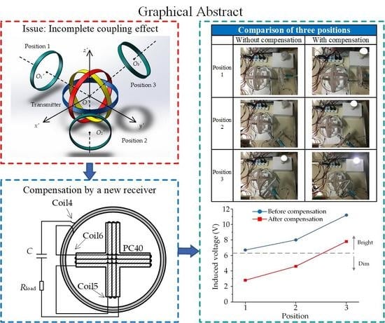
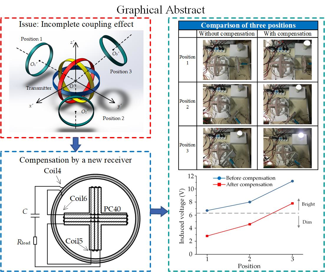
Analysis and Compensation of Incomplete Coupling for Omnidirectional Wireless Power Transfer

1
State Grid Jiangxi Electric Power Co. Ltd Electric Power Research Institute, Nanchang 330096, China
2
School of Electrical and Information Engineering, Tianjin University, Tianjin 300072, China
*
Authors to whom correspondence should be addressed.
Energies 2019, 12(17), 3277; https://doi.org/10.3390/en12173277
Submission received: 23 May 2019 / Revised: 7 August 2019 / Accepted: 20 August 2019 / Published: 26 August 2019
(This article belongs to the Section E: Electric Vehicles)

Abstract

:
This paper proposes a detailed analysis of the incomplete coupling effect in omnidirectional wireless power transfer systems and a compensation method aiming to improve the transmission performance. Recently, omnidirectional wireless charging technologies have been gradually explored and studied. These charging technologies can transmit power to arbitrary directions in three-dimensional space. However, there are still specific regions where the transmitted power capability dramatically drops to an extremely low level due to the incomplete coupling effect. Accordingly, this paper provides a theoretical analysis and compensation of such an effect. The compensation effectiveness is validated by both a simulation and a 7 W experimental prototype. After the compensation, the transmitted power can be improved by 61% to drive the load in a full range of the space.

Graphical Abstract

1. Introduction

Wireless power transfer (WPT) technologies have the capability to transmit power cordlessly, and have attracted more and more attention recently [1]. Compared with the conventional plug-in charging manner, wireless charging can avoid troubles caused by messy wires and aging cables, thus providing with a safer energization environment for various utilizations. Besides, without a direct physical connection between the supplement and the electrical devices, WPT systems can also improve the charging flexibility and convenience, which shows great potential for use in different application fields. For low power demands, WPT technologies can supply the energy required for implanted medical equipment [2], portable consumer devices [3], and sensors [4], etc. On the other hand, this technique can also achieve high-power transmission, such that it has been gradually utilized for the charging of electric vehicles (EVs) [5,6], drones [7], and electric motors [8,9].
With increasing demand, WPT techniques can not only be utilized for static charging but also to deliver power to mobile objectives. Accordingly, this emerging technology is considered a competitive solution for charging battery-powered appliances, where it is able to eliminate the limitations caused by current unsatisfactory battery performance. Dynamic wireless charging has been gradually studied and utilized in many fields, especially for EVs and electronic equipment, which can effectively extend the operation time and expand the application range [10]. For park-and-charge scenarios, the positional requirement for charging is extremely strict, such that strong coupling between the transmitter and receiver can be realized, as well as provide the best transmission performance. Equally, for move-and-charge scenarios, the coupling strength should be maintained in order to achieve a stable power transmission. For this purpose, many efforts have been carried out for dynamic wireless charging, such as the double D-quadrature (DDQ) coil design [11], topology-reconfigurable capacitor matrices [12], and homogeneous WPT techniques [13] etc., which significantly promote the development of dynamic wireless power transfer systems. However, such technologies can only stabilize the coupling effect in one-dimensional (1-D) space, and thus the system performance tends to deteriorate in the case of electric-driven devices, which exist in in three-dimensional (3-D) space and move in multiple directions.
For realizing power transmission in multiple directions, the omnidirectional WPT system has been part of several in-depth studies, since it is able to transfer power to arbitrary spatial directions. In order to generate the electromagnetic field which can be pointed to multiple directions for transmission, a rotary transmitting coil design was proposed for household appliances [14]. The design can enable energy to be transmitted to all directions in two-dimensional (2-D) space without adding extra coils. However, it is difficult to expand such a scheme for 3-D spatial transmission. In addition, a brand-new cubic topology for the transmitter was designed and implemented in [15], which still used only one single source for power input. It has been verified that said transmitter has the ability to transmit power to a load located at arbitrary positions, while the optimal energy distribution strategy for such a scheme still remains to be discussed and solved. For wide popularization, a compact transmitter structure using orthogonal coils is preferred [16,17], as it can achieve both 2-D and 3-D omnidirectional wireless power transfer. Besides, basic control principles for such a topology have also been presented and verified for further research, namely non-identical current control, including current amplitude and phase control methods, which can make the generated electromagnetic field point to arbitrary directions [18]. In [19,20], a transmitter composed of two orthogonal coils was successfully driven to produce a rotatable electromagnetic field by utilizing current amplitude modulation. Additionally, when the input of the transmitting coils were given by sources with a current phase difference of 90°, it was verified that the power also could be transmitted to a mobile receiver in 2-D space [21]. Furthermore, the amplitude control method can be applied to focus the generated electromagnetic field in a specific spatial direction, thus realizing a 3-D omnidirectional wireless charging system, where the transmitter consists of three orthogonal coils [22]. On the basis of a 3-D coordinate, the system performance analysis was analyzed and validated by both simulated and experimental results in [23]. With the merits of flexibility and convenience, such a scheme has been widely accepted for omnidirectional WPT systems. Additionally, in order to realize a wide-range wireless power transfer, a modularized WPT system using direct-quadrature transmitting coils [24] and a coreless transmitter with a conductive magnetic shield [25] were proposed, respectively. Both can generate uniform magnetic fields in a large zone and realize the free-positioning of receivers. To achieve a six degrees of freedom wireless power transfer, a ubiquitous wireless power environment was also studied, which can charge multiple receiver coils freely, suitable for practical applications concerning the internet of things [26].
However, there is still a non-ignorable technical issue for 3-D omnidirectional WPT systems which use the orthogonal transmitter, namely the valley of power transfer capability due to the incomplete coupling effect. Regarding electric-driven appliances, the maximum charging power can dramatically drop to a low level in such specific regions, which inevitably deteriorates the charging performance and user experiences. Accordingly, the full coverage of charging capability is one of the most important research objectives for omnidirectional WPT systems that use orthogonal transmitters. This research has been nearly unexplored in previous studies. In order to address the issues above, this paper proposes a detailed analysis of the incomplete coupling effect, as well as its compensation. The proposed solution can enhance the transmitted power by compensating the coupling effect between the transmitting and the receiver coils, aiming to remove the incomplete coupling effect and improve the performance of omnidirectional WPT systems.
The rest of this paper is given as follows: The detailed theoretical analysis and compensation of the incomplete coupling effect for omnidirectional WPT systems are both proposed in Section 2. Section 3 provides the simulated and measured results to validate the feasibility of the compensation, especially for incompletely coupled positions. Finally, the conclusion is summarized in Section 4.

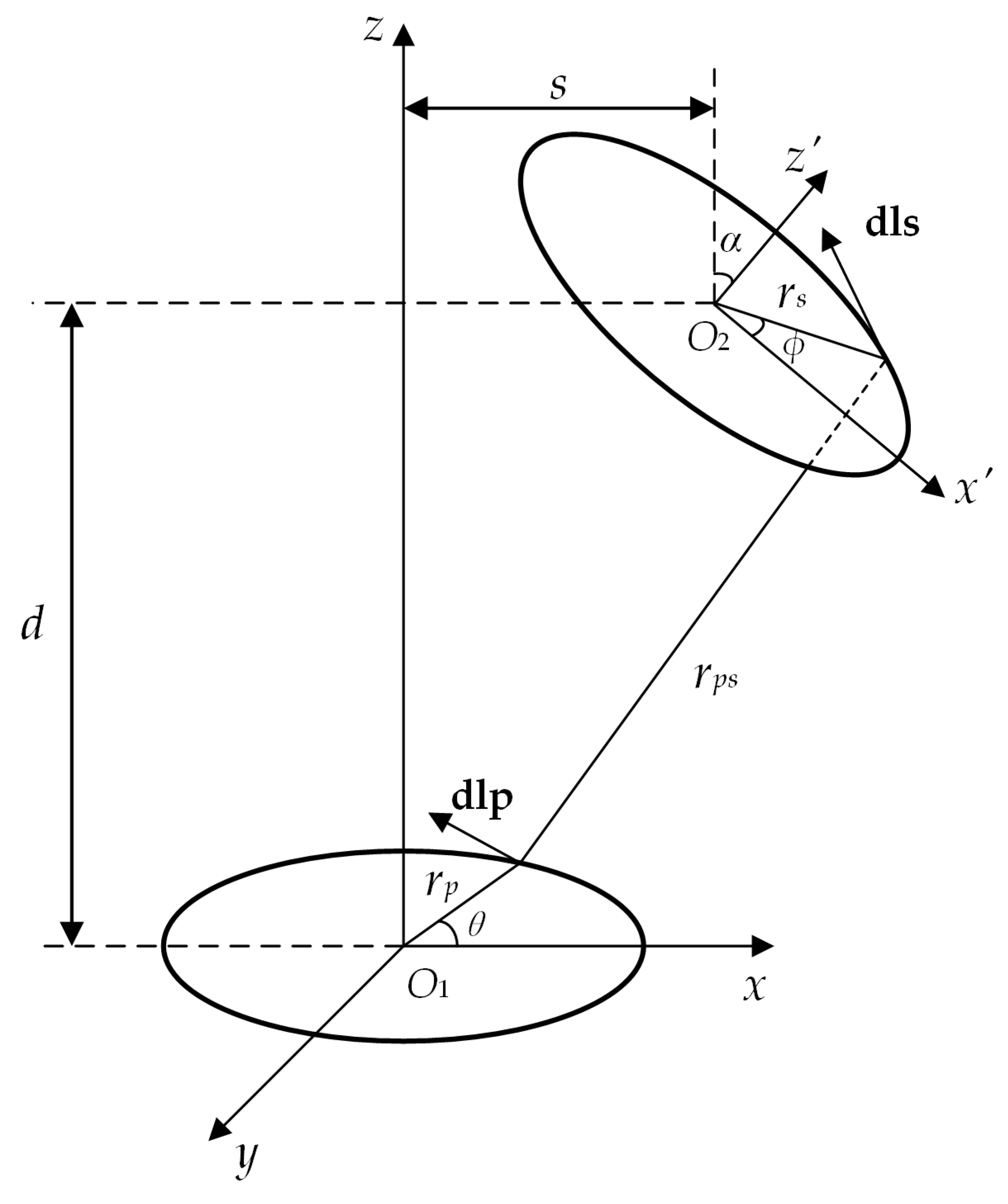
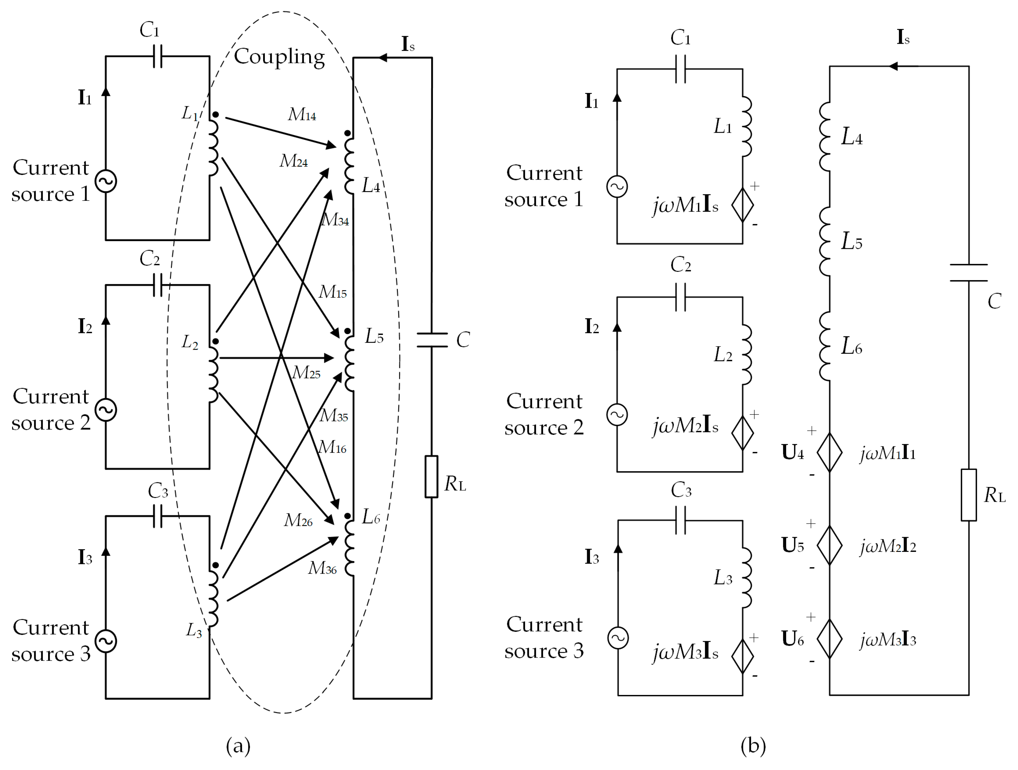
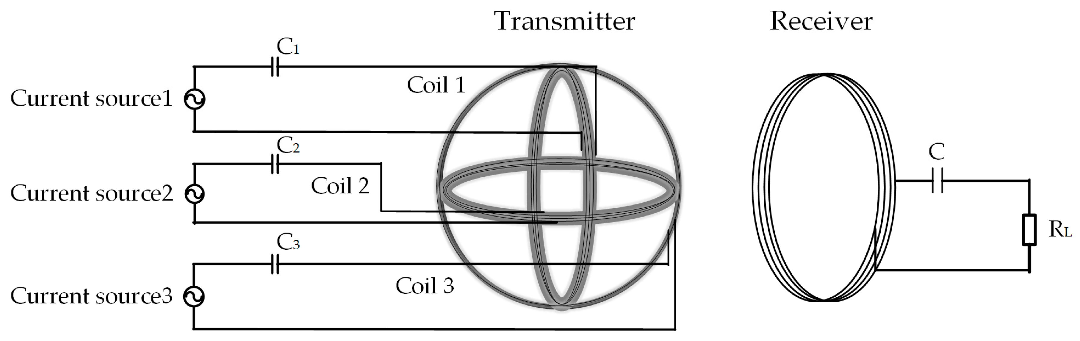
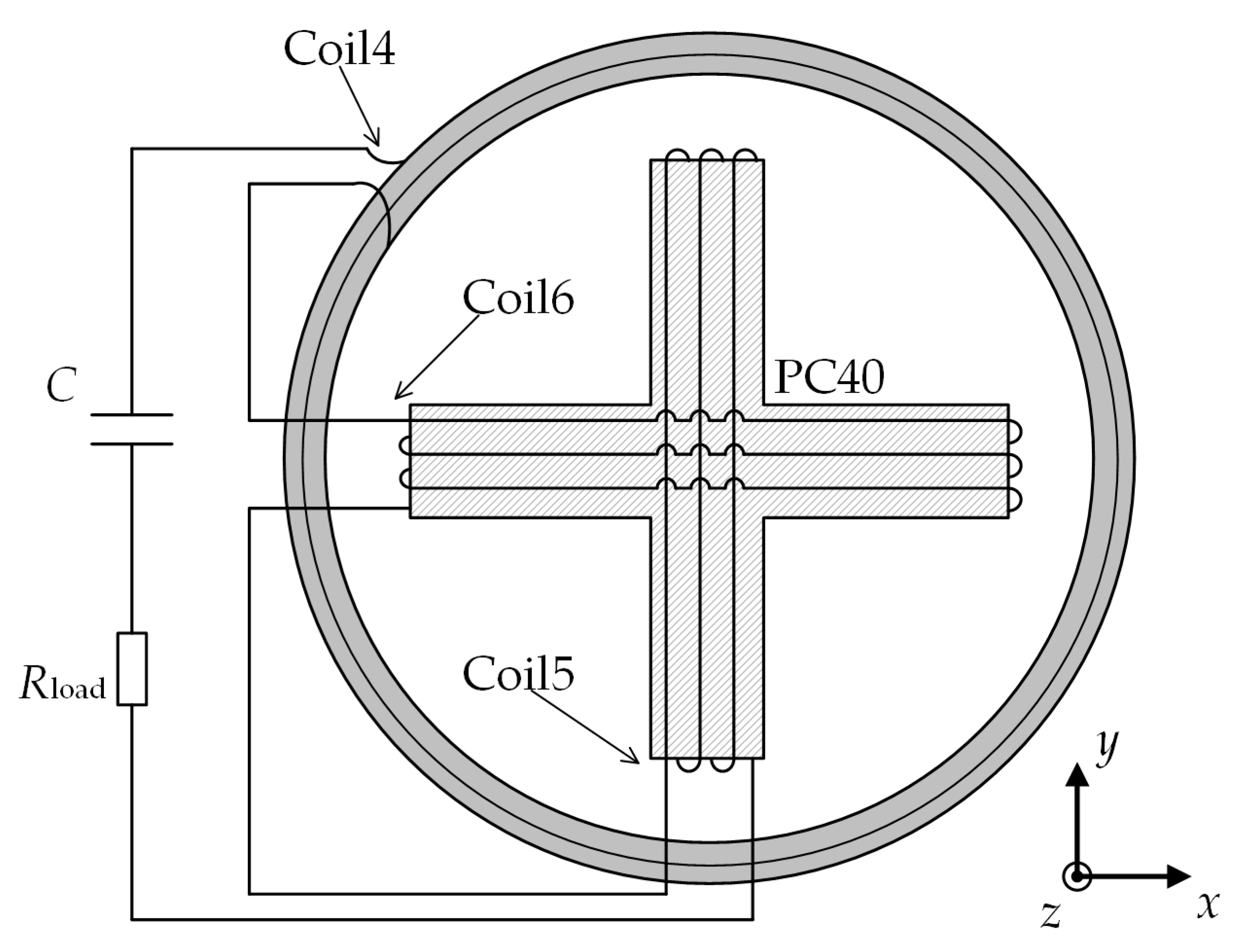
2. Theoretical Analysis and Compensation of the Incomplete Coupling Effect

Figure 1 depicts a typical omnidirectional WPT system, which has a transmitter with three orthogonal coils and a circular receiver. The transmitted power significantly depends on the mutual inductance between the transmitting and receiver coils. As depicted in Figure 2, it shows two spatial coils with lateral and angular misalignments. Here, we denote the magnetic permeability of vacuum as μ0, the turns of coils as Np and Ns, the radii of the coils as rp and rs, the transmission distance as d, and the lateral and angular misalignment as s and α, respectively, where the subscript characters p and s represent the primary and secondary coils. Then, the general mutual inductance of two coils can be given by the following equation [27]:
M G = μ 0 N p N s r p r s 4 π × sin θ sin φ cos α + cos θ cos φ r p s d θ d φ
where the limits of θ and ϕ are both [0, 2π), and
r p s = [ r p 2 + r s 2 + d 2 + s 2 + 2 s r s cos φ cos α 2 s r p cos θ 2 r p r s ( cos θ cos φ cos α + sin θ sin φ ) 2 r s d cos φ sin α ] 1 2
Here, Equation (1) shows that the mutual inductance decreases with the increase of the lateral or angular misalignments, as well as the general misalignment [28]. Then, for omnidirectional WPT systems, the mutual inductance tends to fall to an extremely low value in specific regions where the receiver is perpendicular to one or two transmitting coils, thus inevitably resulting in the decrease of the acquired power of the receiver unit. Accordingly, the maximum transmitted power also dramatically drops to a very low level, especially for such spatial positions as mentioned above, namely incompletely coupled positions. For compensation, the traditional receiver can be replaced by one that has an orthogonal structure, as depicted in Figure 3, which shows a flat shape. Coil 4 has two layers and each layer shows a helical shape, so such a receiver unit has a thin thickness. The two crossed coils are both wound tightly on the PC40. PC40 is a ferrite which has high initial permeability, high saturation magnetic flux density, and low core loss. As a receiver, these coils should be connected in series, as depicted in Figure 3.
For a typical omnidirectional wireless power transfer system, the transmitting coils are fed with independent AC sources, namely I1, I2, and I3. By adopting the same frequency, the adjustable amplitude of the current sources can generate a rotating magnetic field [22]. The transmitter and receiver unit are both connected with compensated capacitors in series, aiming to ensure the resonate working state and optimal transmission performance. Based on the system utilizing the compensation receiver, we denote Li as the self-inductance of the i-th coil, Ri as the internal resistance of the i-th coil, and Mij as the mutual inductance between the i-th and the j-th coils. Due to the orthogonal structure of the transmitting unit and receiver unit, the mutual inductance among the coils of each unit can be ignored [29], namely M12 = M13 = M23 = 0 and M45 = M46 = M56 = 0. Then, the inductive voltage of receiver coils can be calculated as:
[ U 4 U 5 U 6 ] = [ j ω M 14 j ω M 24 j ω M 34 j ω M 15 j ω M 25 j ω M 35 j ω M 16 j ω M 26 j ω M 36 ] [ I 1 I 2 I 3 ]
where U4, U5, and U6 are the voltages inducted by Coil 4, Coil 5, and Coil 6, respectively. Let M1 = M14 + M15 + M16, M2 = M24 + M25 + M26, M3 = M34 + M35 + M36, and Rs = R4 + R5 + R6, according to the coupling relationship shown in Figure 4a, where the equivalent circuit can be obtained as depicted in Figure 4b, which can be given by:
[ U 1 U 2 U 3 0 ] = [ R 1 + j X 1 0 0 j ω M 1 0 R 2 + j X 2 0 j ω M 2 0 0 R 3 + j X 3 j ω M 3 j ω M 1 j ω M 2 j ω M 3 R s + R L + j X s ] [ I 1 I 2 I 3 I s ]
where U1, U2, and U3 are the output voltages of three power sources, and
X 1 = ( ω L 1 1 ω C 1 )
X 2 = ( ω L 2 1 ω C 2 )
X 3 = ( ω L 3 1 ω C 3 )
X s = [ ω ( L 4 + L 5 + L 6 ) 1 ω C ]
Accordingly, the current of the secondary side can be obtained as:
I s = j ω ( M 1 I 1 + M 2 I 2 + M 3 I 3 ) R s + R L + j X s
The amplitude of Is is given by:
I s = ω ( M 1 I 1 + M 2 I 2 + M 3 I 3 ) ( R s + R L ) 2 + X s 2
Then, the load power can be obtained as:
P L = I s 2 R L = ω 2 ( M 1 I 1 + M 2 I 2 + M 3 I 3 ) 2 R L ( R s + R L ) 2 + X s 2
This shows that the key parameters determining the load power are M1, M2, and M3 if the three current sources output the maximum amplitude. For the conventional omnidirectional WPT system, considering the structure of the conventional receiver, the load power can be considered as a special case when M15 = M16 = M25 = M26 = M35 = M36 = 0, which is given by:
P L_con = I s 2 R L = ω 2 ( M 14 I 1 + M 24 I 2 + M 34 I 3 ) 2 R L ( R s + R L ) 2 + X s 2
Figure 5 depicts three typical spatial positions in an omnidirectional WPT system. The plane of the receiver always faces towards the center of the transmitter at such positions. At Position 1, the receiver is perpendicular to two transmitting coils, whose centers are located along the y’-axis. For Position 2, the center of the receiving coil is located in the x’-y’ plane, and accordingly the receiver is perpendicular to only one transmitting coil. Moving to Position 3, which is the most common condition, the center of the receiver is located in the octant instead of the y’-z’ plane. The incomplete coupling effect exists at Positions 1 and 2, due to the perpendicular relationship between the transmitter and receiver. At Position 1, the traditional receiver coil is perpendicular to two transmitting coils, for instance, which causes the values of the mutual inductance M24 and M34 to inevitably drop to zero. Due to the disappearance of the corresponding coupling effect (the incomplete coupling effect), the sources I2 and I3 cannot make contributions to transmit the power according to Equation (12), thus significantly deteriorating the transmission performance, especially for the load power. For such a condition in the conventional omnidirectional WPT system, the only way to improve the load power is to increase the effective source input, namely source I1, while the input is always limited by the tolerance of the transmitting coils, which cannot be increased infinitely in practical applications. Accordingly, the transmitted power at Position 1 becomes much lower than that of the other spatial positions, which results in the valley of power transfer capability in the system, such that the receiver cannot obtain enough power for charging, and thus the system cannot realize a full-coverage of power transmission. As a comparison, when the orthogonal receiver is applied at Position 1 in the system, due to the coupling compensation by Coil 5 and Coil 6, M25 and M36 are prevented from dropping to a low level, even though M24 and M34 still decrease to zero. According to Equation (11), M1, M2, and M3 are maintained, such that all three sources are able to transfer the power. Therefore, the orthogonal receiver has the capability to compensate the coupling effect and enhance the power transmission of the system.
Similarly, at Position 2, M34 tends to decrease to zero when the conventional receiver is only perpendicular to transmitting Coil 3, and therefore it leads to the incomplete coupling effect. According to Equation (12), the system source I3 is not useful for the power transfer, which can also deteriorate the corresponding transmission performance. Due to the limitation of the input, the two effective sources cannot be improved to be as large as what is needed, which also tends to deteriorate the transmission performance. Therefore, at such a position, the maximum power transfer capability also has a dramatic drop due to the incomplete coupling effect, which is harmful to the power transmission. By replacing it with the compensation receiver, M36 will not decrease to zero, such that M3 can be maintained by Coil 6. Accordingly, it can compensate the coupling effect and improve the performance of the system.
Therefore, the incomplete coupling effect existing in conventional omnidirectional WPT systems has a negative effect on power transmission. By comparing the performance difference between the two types of receiver, the compensation receiver has the ability to maintain the coupling effect between the receiver coils and each transmitting coil and improve the transmitted power. Theoretically, it shows great potential to improve the maximum charging power and ensure transmission performance at arbitrary positions in 3-D space, which can effectively address the aforementioned technical issues and ensure the full coverage of omnidirectional wireless power transfer.

3. Results

In this section, the simulation and experimental results are both given to demonstrate the deterioration resulting from the incomplete coupling effect and the feasibility of the compensation. As shown in Figure 5, there are three typical positions for omnidirectional WPT systems, which were adopted for testing in the validation. Among them, Positions 1 and 2 were the incomplete coupling positions, since there exists a perpendicular relationship between the traditional receiver coil and one or two transmitter coils. The operational frequency and transmission distance were set as 100 kHz and 200 mm, respectively.

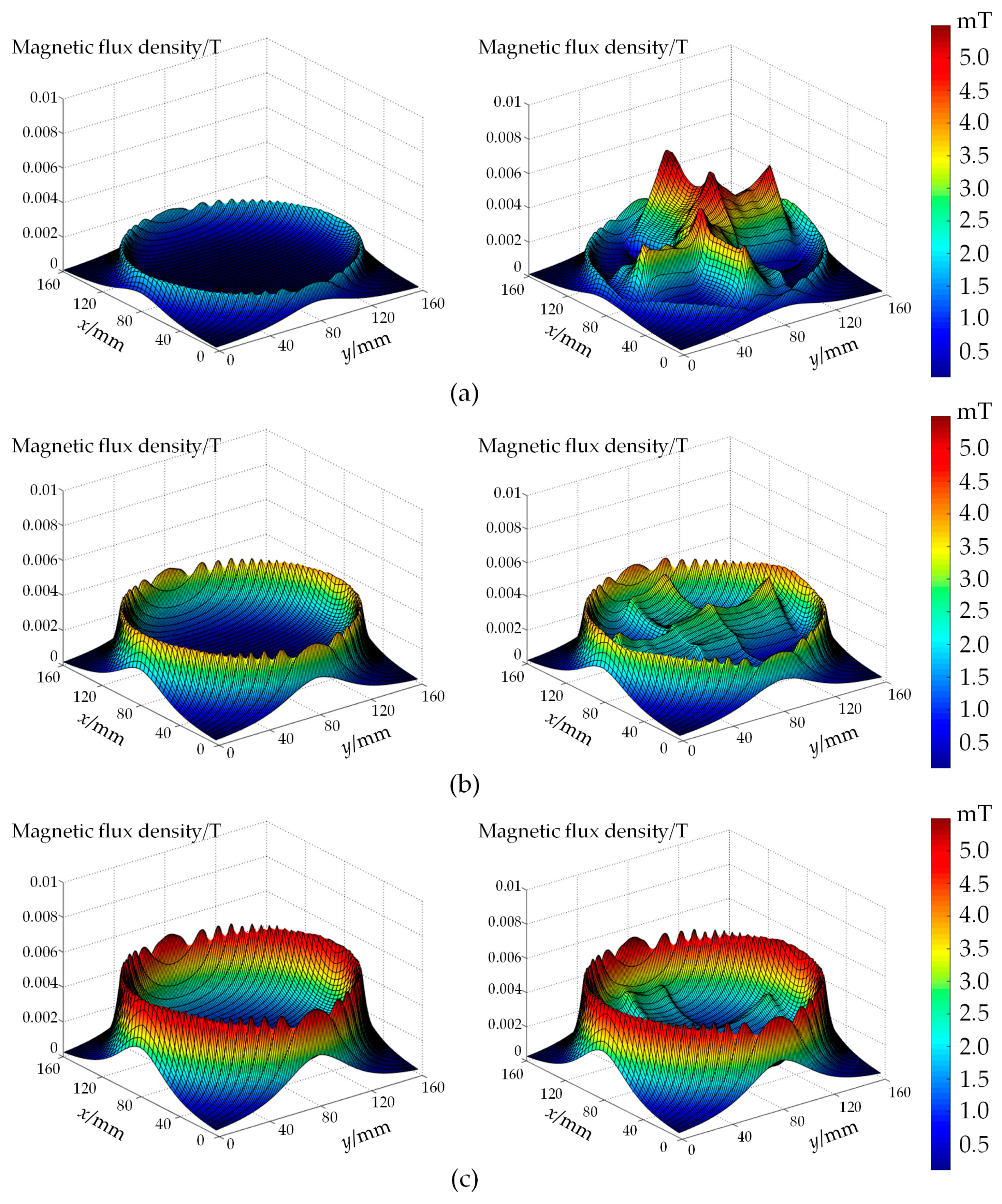
3.1. Simulated Results

A finite element analysis (FEA) electromagnetic software named JMAG (14.0, JSOL Corporation, Tokyo, Japan) was utilized for the simulation. The three transmitting coils were fed with 3 A. Figure 6 depicts the vector plots in PC40 at each testing spatial position, which intuitively shows the distribution of the magnetic flux passing through the two crossed coils of the compensation receiver. As shown in Figure 6a, the magnetic flux goes through both the two crossed coils, and the whole magnetic flux density raises to 0.04 T when the receiver is utilized for compensation at Position 1. This means that after compensation the flux can be effectively gathered and flows through the two crossed coils, such that the induced voltage can be generated in the corresponding coils. Therefore, the coupling effect of the system can be greatly enhanced as well as the transmitted power. When using it at Position 2, the magnetic flux density in PC40 becomes slightly weakened compared with that at Position 1, while the maximum is still up to 0.04 T. As shown in Figure 6b, the magnetic flux mainly flows through Coil 6, such that voltage can be induced in the coil. Accordingly, the incomplete coupling effect can be compensated, and the transmission performance can also be improved. However, the distribution is much less in the core when the receiver moves to Position 3, as shown in Figure 6c, since the magnetic field vector generated by the transmitting unit points to the receiver unit nearly perpendicularly. In such a case, most of the magnetic flux passes through Coil 4, which is quite similar to the condition before for compensation.
Additionally, Figure 7 shows the 3-D distribution of the magnetic flux density on the horizontal plane where the receiver is located. At Position 1, the peak value of the magnetic flux density is 1.9 mT before compensation, which is much lower than the 5.5 mT value when using the proposed scheme. This means that the coupling effect becomes stronger and more power can be transmitted to the receiver after compensation. Moving to Position 2 for further comparison, the maximum magnetic flux density raises up to 3.9 mT and 4.0 mT before and after compensation, respectively. Besides, after compensation, the magnetic flux around the two central coils also is enhanced such that the transmission performance tends to be better than that when using the traditional receiver. In addition, the peak values are both increased for the two conditions at Position 3, namely 5.5 mT and 5.7 mT.
Figure 8 depicts the contour plot that illustrates the strength of the induced magnetic field of the two types of receiver, which intuitively reveals the influence of the receivers on the magnetic flux density. By successively moving the receiver at Positions 1, 2, and 3, the compensation scheme can effectively enhance the induced magnetic field, but the corresponding peak value area transits from the inner coils (Coil 5 and Coil 6) to the outer coil (Coil 4). At Position 1, as shown in Figure 8a, due to the gathering of the magnetic flux caused by PC40, the magnetic flux density is greatly strengthened around the two crossed coils and thus the coupling effect between the transmitter and receiver is enhanced. As shown in Figure 8b, moving to Position 2, the magnetic flux density around the central area still can obviously be improved when compared with the conventional scheme, while the magnetic field around the outer coil shows little difference between the two schemes. Therefore, a better performance can be obtained by utilizing the compensation receiver. For Position 3, the magnetic flux density after compensation is slightly stronger than that before compensation, which has little difference. The results reveal that the compensation method shows important meaning, especially at incompletely coupled positions, namely Positions 1 and 2. Based on the above results, it can be illustrated that the receiver for compensation is capable of enhancing the magnetic field flux density in the space where the receiver is located, thus successfully eliminating the incomplete coupling effect where the receiver cannot acquire the power from omnidirectional WPT systems.
Furthermore, in order to further study the enhancement of the compensation, the comparative results of transmitted power are also given in Figure 9. Here, it is shown that after compensation the WPT system can increase the transmitted power at the three testing positions. In particular, the difference between the two conditions shrinks when the receiver moves from Positions 1 and 2 to a commonly-used area, like Position 3, which illustrates that the compensation method can eliminate the incomplete coupling effect of transmitted power for omnidirectional WPT systems. Besides, it also confirms that the system can enhance the maximum charging power in various spatial regions with the compensation, which agrees with the aforementioned theoretical analysis.

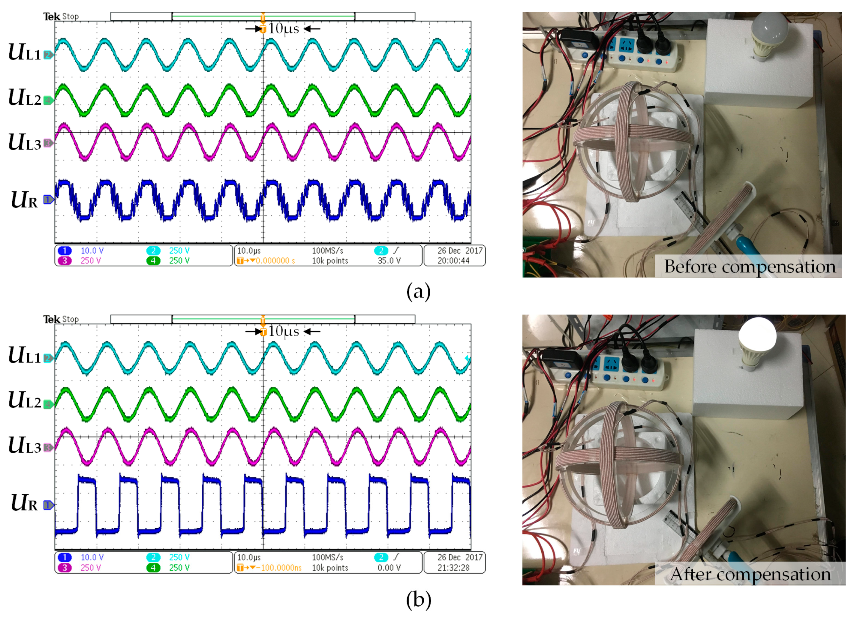
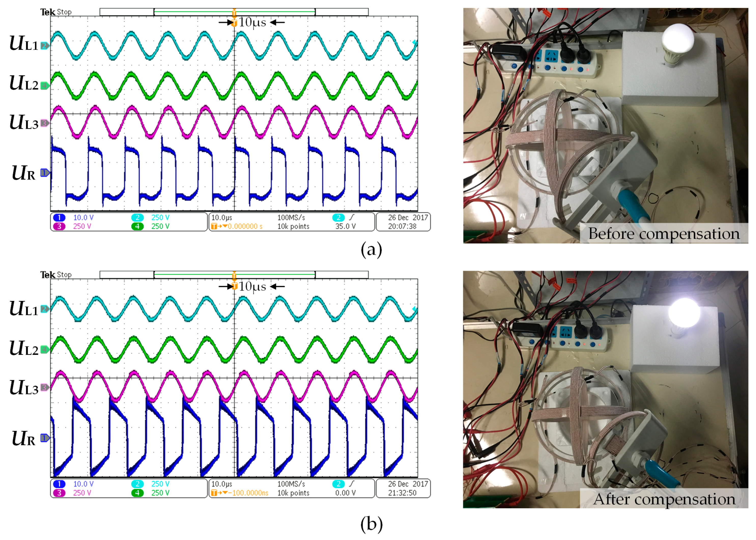
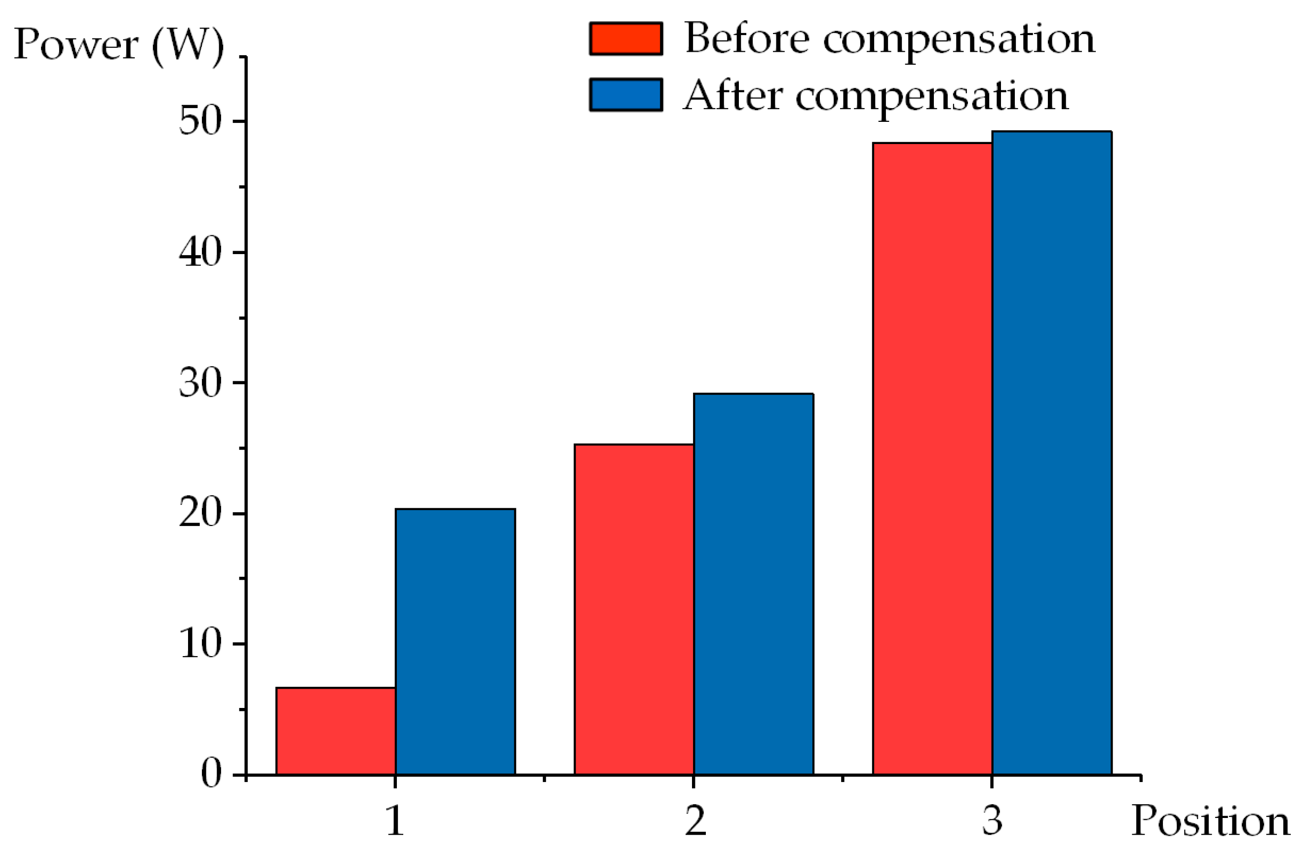
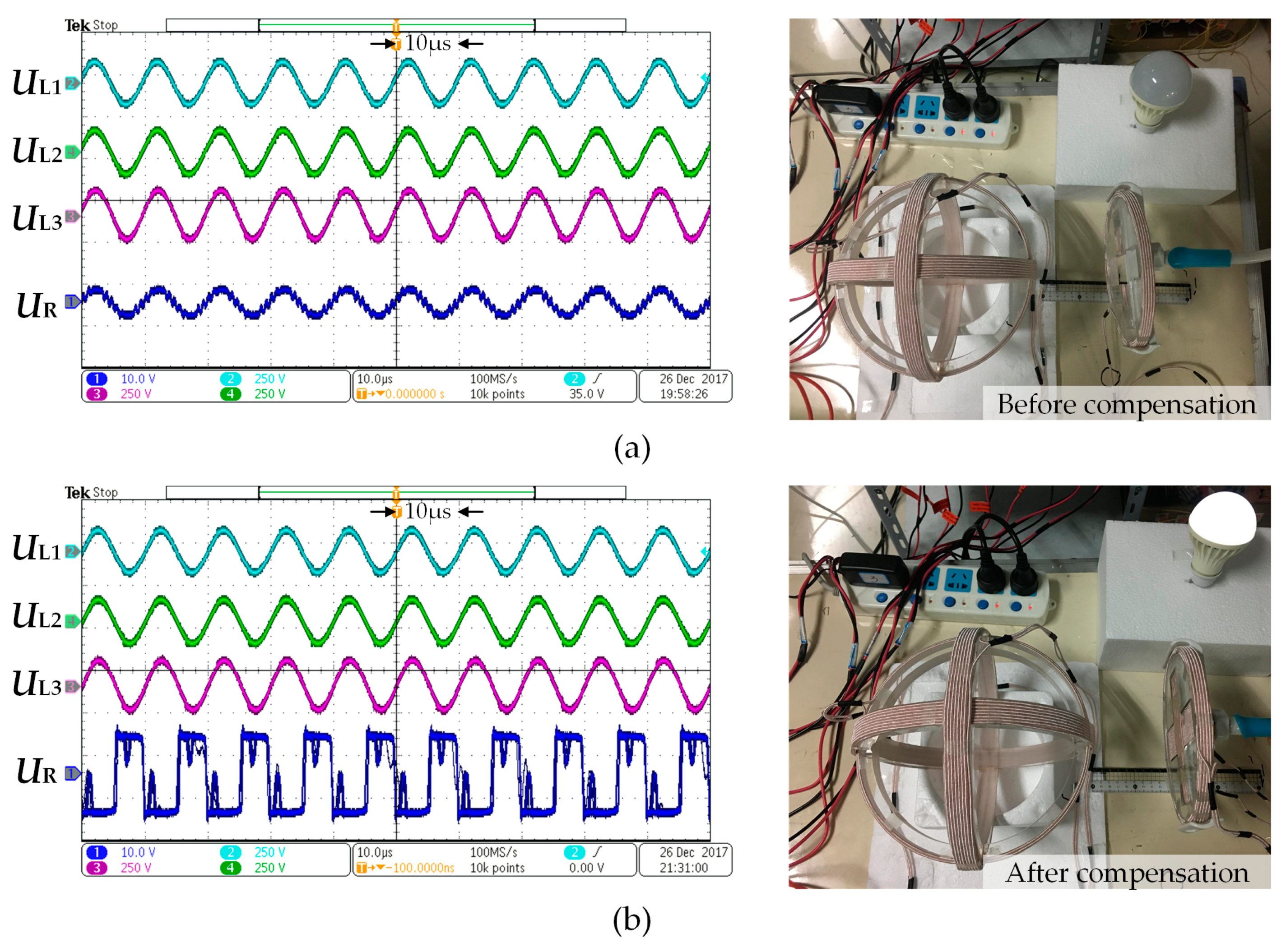
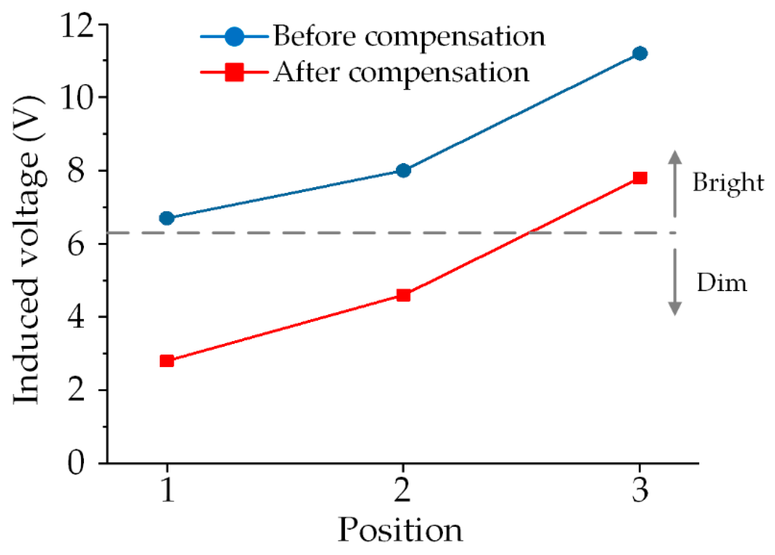
3.2. Measured Results

An experimental prototype was also fabricated to verify the effectiveness of the omnidirectional WPT system after compensation by comparison with the conventional scheme without compensation. The prototype mainly consists of the compensation capacitors, a DC/AC inverter, an orthogonal transmitter, and the receiver for compensation, as shown in Figure 10. All waveforms were measured by utilizing an oscilloscope (Tektronix MDO3024, Tektronix, Shanghai, China). The control scheme was programmed a DSP28335 platform. The three transmitting coils had the same size and were 200 mm diameter. Each transmitting coil has 15-turn windings, whose measured inductance and internal resistances were 101 μH and 0.1 Ω, respectively. The applied receiver for coupling compensation has a 150 mm diameter with an inductance value of 395 μH. Besides, the windings of Coil 4, Coil 5, and Coil 6 were 15, 27, and 27 turns, respectively. The compensation capacitor for each coil was connected in series in the circuit.
In the experimental verification, a 7 W bulb was used as the load. The corresponding brightness and voltage waveforms can visually demonstrate the effectiveness of the compensation scheme. In the measured waveforms, channels 1, 2, 3, and 4 were used to display the load voltage (UR) and the transmitting coils (UL1, UL2 and UL3), respectively.
Figure 11, Figure 12 and Figure 13 shows the experimental results at the three test positions, with and without compensation, respectively. When utilizing the conventional receiver at Positions 1 and 2, Figure 11a and Figure 12a show that the root-mean-square (RMS) value of VR was 2.8 V and 4.6 V. Accordingly, the transmitted power dropped to a low level due to the incomplete coupling effect, such that the transmitted power could not light up the bulb. As shown in Figure 11b and Figure 12b, after compensation, VR increases to 6.7 V and 7.4 V, respectively, thus successfully lighting up the bulb. Besides, under the complete coupling condition, namely Position 3, the proposed receiver can induce a voltage of 11.3 V for VR, while the conventional receiver only has 7.8 V. As shown in Figure 13, the brightness of the bulb can be effectively enhanced by using the compensation, accordingly. In addition, Figure 14 depicts the measured results for comparison. The grey line is the threshold voltage of the bulb. When the induced voltage was lower than the threshold, the bulb could not be lightened, and as long as the induced voltage was larger than the threshold, the bulb could be driven to be bright. From Figure 14, it can be seen that at Positions 1 and 2, the conventional system is unable to transfer enough power to devices in some spatial ranges due to the incomplete coupling effect. Besides, the proposed scheme can effectively enhance the power transfer capability, even at the worst condition, namely Position 1, which can ensure a full-range of power transmission, showing great potential for practical utilizations. Thus, this verifies the improvement of the compensation scheme for the transmitted power, especially for incompletely coupled positions, such as Positions 1 and 2, which is in accordance with the theoretical analysis.

4. Conclusions

This paper has proposed a detailed analysis of the incomplete coupling effect and a compensation scheme for omnidirectional WPT systems. From the simulated and experimental results, the ability of enhancing the maximum transmitted power at incompletely coupled spatial regions has been verified while ensuring transmission performance. The obtained power can be improved by 61% to lighten a 7 W bulb after the compensation for incomplete coupling effect. By comparison with conventional omnidirectional WPT systems, the results have demonstrated that the compensation method can significantly enhance the power transmission and remove the incomplete coupling effect. Thus, ensuring the full coverage of charging capability can be achieved for omnidirectional WPT systems, which shows prospective value for various applications.

Author Contributions

Conceptualization, W.W. and B.Z.; Methodology, B.Z.; Software, Q.L., T.M., and B.Z.; Validation, W.W., H.W., and B.Z.; Formal analysis, J.X. and B.Z.; Writing—original draft preparation, B.Z.; Writing—review and editing, W.W., H.W., Q.L., and B.Z.; Visualization, B.Z.; Supervision, W.W., Z.Z.; Project administration, W.W., Z.Z.; Funding acquisition, W.W.

Funding

This work was supported in part by State Grid Jiangxi Electric Power Company Project “Research on Application Evaluation Technology of Wireless Charging System for Electric Vehicles” (Project No. 521820170020) and in part by the National Natural Science Foundation of China (Project No. 51607120).

Conflicts of Interest

The authors declare no conflict of interest.

References

  1. Zhang, Z.; Pang, H.; Georgiadis, A.; Cecati, C. Wireless power transfer—An overview. IEEE Trans. Ind. Electron. 2019, 66, 1044–1058. [Google Scholar] [CrossRef]
  2. Hui, S.Y.R.; Zhong, W.; Lee, C.K. A critical review of recent process in mid-range wireless power transfer. IEEE Trans. Ind. Electron. 2014, 29, 4500–4511. [Google Scholar]
  3. Hui, S.Y. Planar wireless charging technology for portable electronic products and Qi. Proc. IEEE. 2013, 101, 1290–1301. [Google Scholar] [CrossRef]
  4. Lu, X.; Wang, P.; Niyato, D.; Kim, D.; Han, Z. Wireless charging technologies: Fundamentals, standards and network applications. IEEE Commun. Surv. Tutor. 2016, 18, 1413–1452. [Google Scholar] [CrossRef]
  5. Zhang, Z.; Chau, K.T.; Liu, C.; Qiu, C.; Li, W.; Ching, T.W. A positioning-tolerant wireless charging system for roadway-powered electric vehicles. J. Appl. Phys. 2015, 117, 1–4. [Google Scholar] [CrossRef]
  6. Zhang, Z.; Pang, H.; Lee, C.H.T.; Xu, X.; Wei, X.; Wang, J. Comparative analysis and optimization of dynamic charging coils for roadway-powered electric vehicles. IEEE Trans. Magn. 2017, 53, 9402106. [Google Scholar] [CrossRef]
  7. Zhou, J.; Zhang, B.; Xiao, W.; Qiu, D.; Chen, Y. Nonlinear parity-time-symmetric model for constant efficiency wireless power transfer: application to a drone-in-flight wireless charging platform. IEEE Trans. Ind. Electron. 2019, 66, 4097–4107. [Google Scholar] [CrossRef]
  8. Jiang, C.; Chau, K.T.; Liu, C.; Han, W. Design and analysis of wireless switched reluctance motor drives. IEEE Trans. Ind. Electron. 2019, 66, 245–254. [Google Scholar] [CrossRef]
  9. Jiang, C.; Chau, K.T.; Ching, T.W.; Liu, C.; Han, W. Time-division multiplexing wireless power transfer for separately excited DC motor drives. IEEE Trans. Magn. 2017, 53, 8205405. [Google Scholar] [CrossRef]
  10. Zhang, Z.; Zhang, B.; Deng, B.; Wei, X.; Wang, J. Opportunities and challenges of metamaterial-based wireless power transfer for electric vehicles. Wirel. Power Transf. 2018, 5, 9–19. [Google Scholar] [CrossRef]
  11. Budhia, M.; Boys, J.T.; Covic, G.A.; Huang, C. Development of a single-sided flux magnetic coupler for electric vehicle IPT charging systems. IEEE Trans. Ind. Electron. 2013, 60, 318–328. [Google Scholar] [CrossRef]
  12. Zhang, Z.; Ai, W.; Liang, Z.; Wang, J. Topology-reconfigurable capacitor matrix for encrypted dynamic wireless charging of electric vehicles. IEEE Trans. Veh. Technol. 2018, 67, 9248–9293. [Google Scholar] [CrossRef]
  13. Zhang, Z.; Chau, K.T. Homogeneous wireless power transfer for move-and-charge. IEEE Trans. Power Electron. 2015, 30, 6213–6220. [Google Scholar] [CrossRef]
  14. Liu, G.; Zhang, B.; Xiao, W.; Qiu, D.; Chen, Y.; Guan, J. Omnidirectional wireless power transfer system based on rotary transmitting coil for household appliances. Energies 2018, 11, 878. [Google Scholar]
  15. Nam, H.; Seo, C. Analytical and experimental investigations of omnidirectional wireless power transfer using a cubic transmitter. IEEE Trans. Ind. Electron. 2018, 65, 1358–1366. [Google Scholar]
  16. Zhang, Z.; Zhang, B.; Wang, J. Optimal design of quadrature-shaped pickup for omnidirectional wireless power transfer. IEEE Trans. Magn. 2018, 54, 8600305. [Google Scholar] [CrossRef]
  17. Ng, W.; Zhang, C.; Lin, D.; Hui, S.Y.R. Two- and three-dimensional omnidirectional wireless power transfer. IEEE Trans. Power Electron. 2014, 29, 4470–4474. [Google Scholar] [CrossRef]
  18. Zhang, C.; Lin, D.; Hui, S.Y. Basic control principles of omnidirectional wireless power transfer. IEEE Trans. Power Electron. 2016, 31, 5215–5227. [Google Scholar]
  19. Lin, D.; Zhang, C.; Hui, S.Y.R. Mathematical analysis of omnidirectional wireless power transfer—Part-I: two-dimensional systems. IEEE Trans. Power Electron. 2017, 32, 625–633. [Google Scholar] [CrossRef]
  20. Lin, D.; Zhang, C.; Hui, S.Y.R. Power and efficiency of 2-D omni-directional wireless power transfer systems. In Proceedings of the 2015 IEEE Energy Conversion Congress and Exposition (ECCE), Montreal, QC, Canada, 20–24 September 2015; pp. 4951–4958. [Google Scholar]
  21. Che, B.; Meng, F.; Wu, Q. An omnidirectional wireless power transmission system with controllable magnetic field distribution. In Proceedings of the 2016 IEEE International Workshop on Electromagnetics: Applications and Student Innovation Competition (iWEM), Nanjing, China, 16–18 May 2015; pp. 1–3. [Google Scholar]
  22. Lin, D.; Zhang, C.; Hui, S.Y.R. Mathematic analysis of omnidirectional wireless power transfer—Part-II three-dimensional systems. IEEE Trans. Power Electron. 2017, 32, 613–624. [Google Scholar] [CrossRef]
  23. Lin, D.; Zhang, C.; Hui, S.Y.R. Omni-directional wireless power transfer systems using discrete magnetic field vector control. In Proceedings of the 2015 IEEE Energy Conversion Congress and Exposition (ECCE), Montreal, QC, Canada, 20–24 September 2015; pp. 3203–3208. [Google Scholar]
  24. Lee, E.; Sohn, Y.; Choi, B.; Han, S.; Rim, C. A modularized IPT with magnetic shielding for a wide-range ubiquitous Wi-power zone. IEEE Trans. Power Electron. 2018, 33, 9669–9690. [Google Scholar] [CrossRef]
  25. Choi, B.; Sohn, Y.; Lee, E.; Han, S.; Rim, H.; Rim, C. Coreless transmitting coils with conductive magnetic shield for wide-range ubiquitous IPT. IEEE Trans. Power Electron. 2018, 34, 2539–2552. [Google Scholar] [CrossRef]
  26. Lee, E.; Choi, J.; Son, H.; Han, S.; Rim, C. Six degrees of freedom wide-range ubiquitous IPT for IoT by DQ magnetic field. IEEE Trans. Power Electron. 2017, 32, 8258–8276. [Google Scholar] [CrossRef]
  27. Yang, Y.; Liu, F.; Chen, X. A maximum power point tracking control scheme for magnetically coupled resonant wireless power transfer system by cascading SEPIC converter at the receiving side. In Proceedings of the 2017 IEEE Applied Power Electronics Conference and Exposition (APEC), Tampa, FL, USA, 26–30 March 2017; pp. 3702–3707. [Google Scholar]
  28. Liu, F.; Yang, Y.; Jiang, D.; Ruan, X.; Chen, X. Modeling and optimization of magnetically coupled resonant wireless power transfer system with varying spatial scales. IEEE Trans. Power Electron. 2017, 32, 3240–3250. [Google Scholar] [CrossRef]
  29. Fang, W.; Son, H. Inductance calculation for orientation position by extended DMP model. In Proceedings of the 2013 IEEE/ASME International Conference on Advanced Intelligent Mechatronics, Wollongong, NSW, Australia, 9–12 July 2013; pp. 774–779. [Google Scholar]
Figure 1. Schematic of a typical omnidirectional wireless power transfer system.
Energies 12 03277 g001
Figure 2. Schematic of spatial coils with lateral and angular misalignment.
Energies 12 03277 g002
Figure 3. Receiver with orthogonal structure for compensation.
Energies 12 03277 g003
Figure 4. Schematics: (a) Coupling relationship; (b) equivalent circuit.
Energies 12 03277 g004
Figure 5. Typical positions for omnidirectional wireless power transfer (WPT) system.
Energies 12 03277 g005
Figure 6. Vector plots in PC40 at: (a) Position 1; (b) Position 2; (c) Position 3.
Energies 12 03277 g006
Figure 7. Three-dimensional (3-D) distribution of magnetic flux density: (a) Position 1; (b) Position 2; (c) Position 3.
Energies 12 03277 g007
Figure 8. Contour plot of magnetic flux density with receiver at: (a) Position 1; (b) Position 2; (c) Position 3.
Energies 12 03277 g008
Figure 9. Comparative results of transmitted power.
Energies 12 03277 g009
Figure 10. Experimental prototype with compensation.
Energies 12 03277 g010
Figure 11. Experimental results at Position 1 (Ch1: 10.0 V/div, Ch2: 250 V/div, Ch3: 250 V/div, Ch4: 250 V/div): (a) without compensation; (b) with compensation.
Energies 12 03277 g011
Figure 12. Experimental results at Position 2 (Ch1: 10.0 V/div, Ch2: 250 V/div, Ch3: 250 V/div, Ch4: 250 V/div): (a) without compensation; (b) with compensation.
Energies 12 03277 g012
Figure 13. Experimental results at Position 3 (Ch1: 10.0 V/div, Ch2: 250 V/div, Ch3: 250 V/div, Ch4: 250 V/div): (a) without compensation; (b) with compensation.
Energies 12 03277 g013
Figure 14. Comparative experimental results.
Energies 12 03277 g014

