1. Introduction
Microgrids are electrical grid entities with clear delimitations from the main grid. They are normally connected to the main grid via one point only [
1,
2], and they are using their own (intelligent) operation and balancing management system [
3]. One of the first attempts in defining the microgrid concept was done by the Consortium for Electric Reliability Technology Solutions program (CERTS) in their report from October 2003 [
4,
5]. Here, a microgrid was defined as a group of micro-generators and storage-units able to separate and isolate itself from the main grid with little or no disruption to connected loads. The distributed energy resources (DER) that play the role of the generation system in the microgrid are often interfaced through power electronic inverters, forming an inverter-based microgrid [
6].
Inverter-interfaced energy resources behave completely different compared to synchronous generators [
7], and thus a plethora of novel operation and control solutions were proposed for power electronics interfaced microgrids [
8,
9,
10,
11,
12,
13,
14,
15,
16,
17]. The stability and power-sharing mechanisms from the classical power systems are not suitable for the operation and control of islanded microgrids. Thus, the research directions are focusing on two major approaches: (a) from a control theory perspective, dominant approaches are small-signal stability assessments, normally considering very basic microgrid architectures [
8,
9,
10] complemented by methods for model order reduction to further asses the high nonlinearity of a closed-loop model [
11,
12]; (b) while from a power system perspective, the common approaches in the literature are looking into the dynamics of the inverter using frequency droop control methods [
13,
14,
15,
16,
17]. Despite very diverse stability assessments in microgrids from the control theory perspective—ranging from radial [
18] to meshed configurations [
7] with a plethora of control strategies from decentralized to hierarchical or distributed methods [
17]—these studies are all trying to mimic the mechanical-inertia mechanism of the traditional power systems with large synchronous generators. Comprehensive and exhaustive reviews in this perspective are given in [
19,
20,
21].
Inertia in power systems acts as a natural opposition of the rotating masses (on the mechanical side) to sudden changes in the frequency (on the electrical side), with a specific deployment time up to 5 s [
22,
23]. However, the most important dynamics are experienced during the first 1 to 2 s after the perturbation. In order to avoid counter-actions, the automatic control loops are designed with delayed intervention. The primary loop starts to operate after 2 s (in general considered to be the fastest), with the primary reserve which must be fully deployed within 30 s [
22,
23], then followed by the secondary control loop. The European Network of Transmission System Operators for Electricity (ENTSO-E) defines inertia as “the property of a rotating rigid body, such as the rotor of an alternator, such that it maintains its state of uniform rotational motion and angular momentum unless an external torque is applied” [
24].
The latest problem is indeed a difficult task when rotational machines and solid-state inverters are co-participating in parallel in the islanded microgrid. The mix of rotating machines in the separated island, working together with the inverter-based generators (specific to renewable energy systems and to the storage devices) is perceived by the network operator as a challenge in terms of system inertia. Thus, when the microgrid operates in an isolated mode, only a minor mechanical inertia is available. The most popular countermeasure is the use of virtual synchronous generator (VSG) control techniques implemented into inverter-based energy resources (IbER) in frequency controlled microgrids [
25,
26,
27], while participation to the power balancing mechanisms is also supported through frequency-based droop control of a selected part of the distributed generation.
This effort of simulating rotational inertia behavior with the inverters is pursued as well because scholars consider that this mechanism is still needed when rotational machines and inverters coexist. Thus, scholars approaching the hybrid configurations of rotational machines and inverter-based energy resources consider implementing the latest, so called Virtual Synchronous Generator/Machine (VSG/VSM) functionality. This functionality is often simulated with various methods of the behavior of a synchronous generator—especially the swing equation. In [
25], a microgrid with inverter generators only is studied, and all energy resources are provided with VSG functionality. A complex mathematical model based on Hamiltonian energy function analyzes how power equilibrium is made without clear information about the unbalance which may occur—even in islanded mode. The study shows that VSG can be a good candidate for the microgrid functionality; however, it comes with the price of a complex approach due to its dependency on frequency of the output power, which is an additional degree of freedom in the system that requires high level analysis. In [
26], an outstanding analysis in the same VSG dependent environment, swinging from Synchronous Generator (SG) to inverter-dominant environment, reaches the conclusion that there is “an unstable region for inverter-dominated islanded microgrid” and that “the identified unstable region provides an important basis for the parameter tuning of VSG operating in an island microgrid”. The paper emphasizes the complexity of having mixed SG and IbER or VSG-driven IbER. While these are valuable approaches for transitioning the grids towards a large penetration of renewables, as well as for microgrids with both conventional and inverter-based energy resources, they do not address the potential advantages of fully inverter-based microgrids. A comprehensive literature survey treating this subject could be found in [
27], where the open question concerning the frequency-oriented stability should be further expanded for the general case of low-inertia systems towards 100% renewables. In our paper, the VSG paradigm is not employed, as we assume that no synchronized rotational generators will be used in the future microgrids, and that the frequency is no longer important. Therefore, the only control parameter is the voltage—which is much easier to handle.
In the classical analysis of power system stability, we find in [
22] that: “power system stability may be broadly defined as that property of a power system that enables it to remain in a state of operating equilibrium under normal operating conditions and to regain an acceptable state of equilibrium after being subjected to a disturbance” and “in the evaluation of stability, the concern is the behavior of the power system when subjected to a transient disturbance. The disturbance may be small or large”. Furthermore, the power system stability is classified in: (a) “angle stability”, (b) “frequency stability” and (c) “voltage stability”.
For the proposed type of microgrid used in this study, the first two are irrelevant since all the inverter-based energy resources—except for the SST which acts as a “grid-former”—are dealt with by means of the phase locked loop (PLL) synchronization unit under grid following strategy. Therefore, the only stability category relevant in this context is the voltage stability. Following the definitions from [
22], stating that “voltage stability is the ability of a power system to maintain steady acceptable voltages at all the busses in the system under normal operation conditions and after being subjected to a disturbance,” and “voltage instability is essentially a local phenomenon”, in this paper we propose an approach that ensures the microgrid stability against fast dynamic disturbances.
Our direction of analysis follows the microgrid architecture solutions, integrating inverter-based energy resources only by employing a solid-state transformer (SST) in order to asynchronously interface the microgrid with the main grid, also assuming uninterrupted operation between the two. However, by assuming this microgrid-by-design-architecture, the islanded type operation strategy can easily be implemented into the microgrid, while the main grid can support the microgrid by providing the necessary active power. Note that there is no anti-islanding protections and automation; however, instead it has all the means to operate always as a grid on its own.
The general concepts of the SST are not presented in this paper, as they have been already addressed in [
1], where it has also been developed as a proof of concept on the SST-based microgrid with inverter-based energy resources only. The simulations presented in [
1] investigated a simplified microgrid, and the essential role of the capacitor on the DC busbar of the SST for the dynamic stability of the microgrid during the disturbances was emphasized. Although the proof hinted at the role of “electrostatic inertia” played by the capacitor (having the ability to release or to absorb the energy needed by the AC microgrid during sudden changes of power) more complex simulations and analysis are required.
The current paper goes a step forward and extends in more details the contribution of the electrostatic energy provided by the DC busbar capacitor on the voltage stability of the microgrid. Thus, a more complex and realistic AC microgrid is investigated and the scenarios defined are intended to link the inertia of the SST-microgrid with a voltage stability issue.
Tests with appropriately chosen disturbances were carried out in the MATLAB/Simulink environment, and the instantaneous values of voltages and currents during relevant time windows have been analyzed. Furthermore, the assessment of voltage stability limits in the microgrid have been carried out by a continuation power-flow procedure in order to select appropriately stressful scenarios for the SST-based microgrid.
The main contributions of this work are summarized as follows:
The control of a solid-state transformer (SST) based microgrid-by-design-architecture (MDA) was developed. The dynamic stability was then evaluated in a microgrid with suitable complexity, focusing on the electrostatic inertia that can be provided by the capacitor on the DC busbar behind the SST inverter topology.
A simulation model was implemented in Simulink, consisting of the SST model and an AC distribution microgrid that includes several inverter-based energy resources and RLC loads.
A correlation between the kinetic inertia and the electrostatic inertia is explained. Note that this “electrostatic energy inertia” principle is different than the classical stability principle of the synchronous power systems, which is based on the mechanical inertia of rotating machines. The latest is neither needed nor desired to be part of the dynamic stability means of the microgrid consisting of inverter-based energy resources only.
The findings from the simulations support and consolidate the concept that a different stability principle needs to be applied in AC microgrids consisting of inverter-based energy resources only, where the electrostatic energy inertia provided by the capacitors from the DC busbar behind the inverters play a very important role. This is a refinement and generalization of previous works [
1,
28,
29], which brings a systematization of such microgrids for the inertia (as a natural reaction to disturbances) and primary control (as man-made automated response to disturbances).
We show that there is little or no frequency dependency in inverter-based microgrids. Thus, one may find new ways of using this flexibility, either by keeping a fixed frequency— no matter the unbalance of the situation—or by using the grid frequency as a power line communication to give signals for droop control implementations at inverter-based energy sources spread in the microgrid network.
The rest of the paper is organized as follows: in
Section 2, the microgrid stability criteria based on electrostatic energy of capacitors behind the inverters is presented. As the capacitors from the DC busbar behind the inverters are the main stabilizers of AC voltage in MDA, the analysis of the system stability is defined only as a voltage stability problem. Note that due to the SST’s decoupling properties, there is no need for frequency related stability formulation.
For deriving the microgrid’s operation and stability limits, a relatively complex low voltage microgrid is chosen. Then, we determine the voltage stability limits and consider them as inputs to further scenarios.
Section 3 describes the scenarios used for simulations, which aim at identifying the boundaries between the stable and unstable operation of the microgrids, in terms of the amount of the energy stored in the capacitor of the SST. Specific disturbances are chosen in the microgrid, based on the limits determined by steady-state calculations in the previous section. Having these limits, we analyze the capability of the SST to maintain its role as grid-former and to maintain the voltage stability within a new scenario.
The scenarios are intended to determine the impact of sudden changes in loads and photovoltaic (PV) production on the SST operation in terms of power exchange with the main grid— each of them being harsh tests (deep disturbances) to assess the voltage stability of SST.
Section 4 details the simulations, interprets and discusses the results. The conclusive remarks and future work considerations are provided in
Section 5.
2. An Analysis of the Meaning of Inertia
In classic power systems, the mechanical inertia constant, denoted by
H, represents the time (in seconds) a generator can provide the rated power using the kinetic energy,
Ekin, stored in the rotating mass, which is defined as [
30]:
where
J is the combined moment of inertia of the generator and turbine [kg×m
2],
ω0m is the nominal speed of rotation [mech.rad/s],
fm is the rotating frequency of the machine and
Sb is the base power, taken equal to the rated power of the generator.
The dynamic behavior of a synchronous machine is governed by the swing equation [
22,
23]:
which shows that any unbalance between the mechanical torque,
Tm, and the electromagnetic torque,
Te, will result in a proportional change in the rotor speed,
ωm, and thus in the frequency, as ω = 2πf. However, the magnitude of the change in the rotor speed (nadir value) is limited by the mechanical inertia. The bigger the inertia constant the smaller the frequency drop.
Equation (2) shows the critical role of the mechanical inertia in limiting the speed of system degradation in terms of frequency (occurring naturally), until man-made automations start. Mechanical inertia is associated with a progressive release of the energy that opposes the rotor frequency to freely fall, thus limiting the nadir value [
30].
In this work we aim to show that a similar inertial role is played by the electrostatic energy stored in DC capacitors, that are behind the inverters, under the form of a so-called “electrostatic energy inertia” (ELEI), which limits the microgrid voltage to fall too deep and provides the MDA with a ride-through during the microgrid disturbance. In a fully inverter-based microgrid, this inertia helps stabilize the DC voltage through the DC capacitor, which naturally releases electrostatic energy while its voltage is decreasing. ELEI is a phenomenon that occurs in a similar way with the mechanical inertia, while voltage regulation systems act to recover the voltage level in due time.
The energy stored under electrostatic form in a DC capacitor (behind the inverter) is expressed as:
where
CDCbus is the capacitance of the capacitor behind the inverter [μF], and
UDC is the DC busbar voltage [V].
The electrostatic inertia constant can be achieved by referring to the base power, i.e.,:
where
UDCnom is the nominal DC voltage [V]; and
Pbase is the base power [W], taken equal to the rating of the converter.
In AC systems the mechanical inertia is dependent on frequency, whereas in DC systems the electrostatic inertia is dependent on the voltage. While the electrostatic energy is present in both AC and DC systems, the electrostatic energy available in the DC system that can be used to support the AC system voltage stability is of importance. In order to maintain the amplitude of the AC voltage around the desired value, the amplitude of the DC voltage must be higher than the amplitude of the AC voltage. The control is performed by means of the power converter and other equipment from the DC system. The simulations performed in this paper are intended to explain this statement.
A comparison between AC and DC grids primary control strategies made in [
29] and [
31], while the importance of energy stored in the capacitor connected in a DC system is considered. However, a generalization of the role of a DC capacitor in the control of both AC and DC networks was not performed. The similarity between rotational inertia and the energy stored in the DC link capacitance of a distributed energy resource (DER) has also been simulated and reported in [
32], where synthetic inertia was emulated by controlling the current provided by the battery energy storage systems (BESS) based on the rate of change of the bus voltage (RoCoV). However, a distinct mechanism for the stability assessment in this case was not clearly identified.
Here, we studied the dynamic stability in microgrids, consisting of only inverter-based energy resources, by focusing on the role of the capacitor from the DC busbar behind the inverter as a device responsible to provide the necessary “electrostatic energy inertia”. In order to enhance the capability of the DC capacitor behind the inverter we employed a BESS aiming at controlling the DC busbar voltage. A PI controller is employed in the DC/DC converter which aims at controlling the DC voltage. We also analyzed the effects of the PI settings on the DC voltage stability.
From hereafter, the following convention of notations are used to express voltage in AC and DC sides of the power network: all DC voltages are denoted by the letter “U” with the corresponding subscript needed, whereas for AC systems the letter “V” is used to denote the phase-to-ground voltages, while “U” is used for phase-to-phase voltages.
3. Aspects Related to Voltage Static Stability in Microgrids
In our previous work we showed that SST separates the main grid from the microgrid in a way which allows for robust microgrid functionality by design [
1]. In such an architecture the microgrid stability is therefore mainly voltage oriented. The purpose of this section is to choose appropriate test scenarios that can challenge the SST grid-former role, based on the electrostatic inertia of its DC busbar capacitors.
In order to be able to test the microgrid at all its limits, the general voltage stability problem is first scrutinized. According to previous works [
22,
23,
33,
34,
35], in AC transmission grids the main cause that may trigger voltage instability is the high loading of the line sections following the increasing load. The voltage drops slowly, and the reducing voltage level causes the current to increase—which produces a rapid voltage drop. This happens especially if appropriate reactive power reserves are not available. The voltage finally collapses if a critical value (
Vcr) is reached. For economic reasons or because of rapid expansions, many distribution grids are undersized, and voltage may become unstable in both steady-state and dynamic conditions.
The voltage stability is usually analyzed based on the approach depicted in
Figure 1 [
22,
35].
The load characteristic within this network can be variated, and thus, we can obtain the characteristic of
P and
V in node 2, according to
Figure 1b, with β as the argument of the line impedance
Z, and φ as the argument of the line current
I.
Following specific calculations, we infer that the maximum power that can be transferred from the source to the load,
P2max, in a radial configuration as in
Figure 1a, is a function of the source voltage
V1 and the load resistance. Equation (5) is achieved assuming a resistive load (φ = 0, which means that
V2 and
I are in phase) and a line with resistive characteristics (
Z = R thus β = 0, as can be approximated for LV microgrids), that is:
which means that the maximum transmissible power is obtained for a voltage at the load bus equal to half of the voltage at the source (which is obtained when the impedance of the source is equal with the impedance of the load). This situation corresponds to the well-known law of maximum transmissible power, which happens when the impedance of the source and that of the load are equal (in this case
RLine =
RLoad).
For any situation with the load power beyond this point, the network is not stable anymore. In practice, if the powers in the load nodes are higher than the limit, then the load-flow models do not converge anymore.
Compared to the microgrid configuration simulated in [
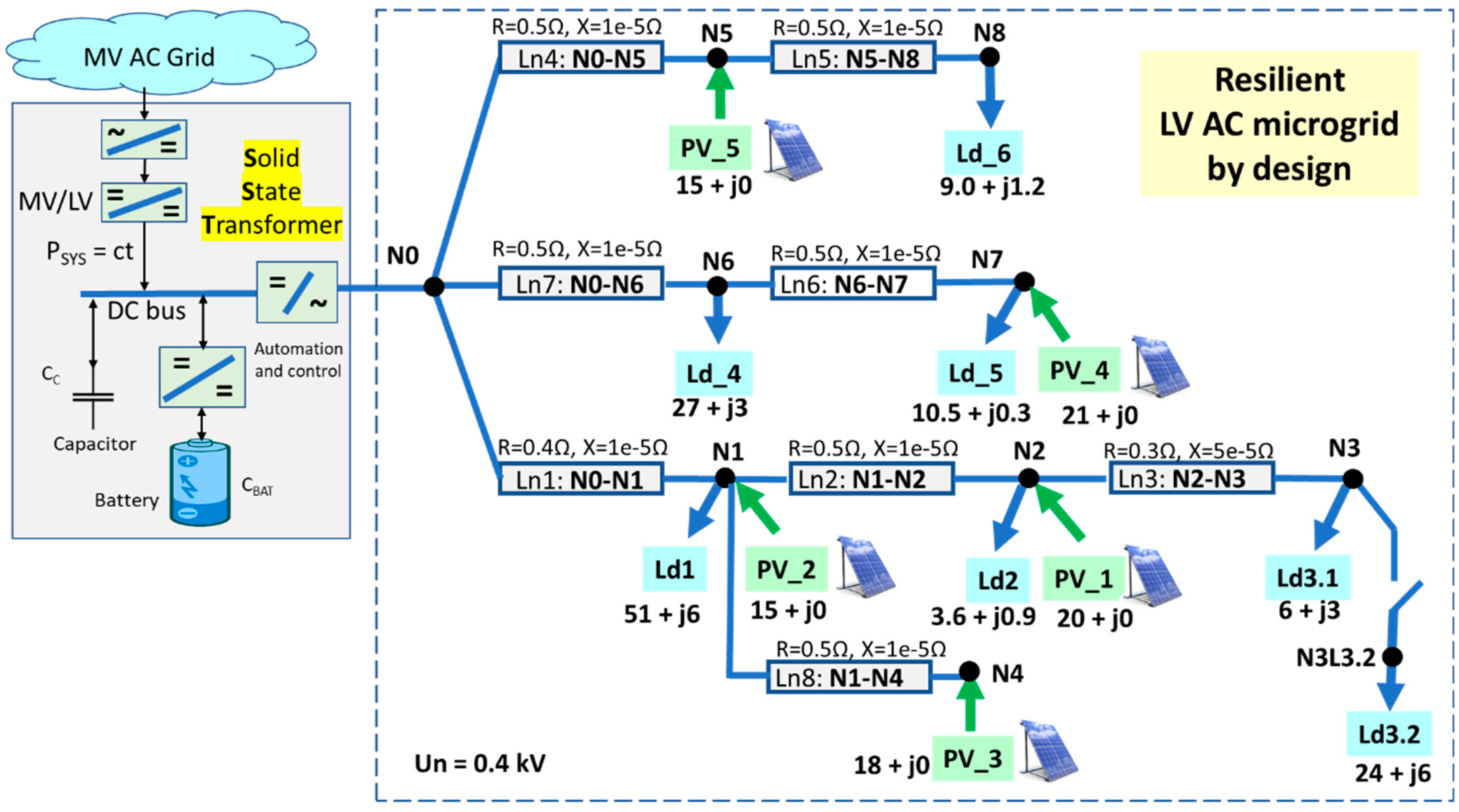
1], in this present case a more complex and realistic microgrid is assumed, with additional scenarios of deep disturbances defined to test the microgrid stability limits. A complex enough microgrid is in
Figure 2, consisting of eight nodes divided on three initial radial branches, as well as five PV generation units.
To determine the voltage stability limit for such a microgrid, one has to consider combined scenarios. For this purpose, and to achieve realistic results, the network was implemented in OpenDSS [
36,
37,
38], which is already a recognized tool used in many other grid studies [
39,
40,
41]. A progressive increase of load Ld3.2 has been applied, and a corresponding set of OpenDSS load flows have been calculated with the multi-calculation mode available with this tool.
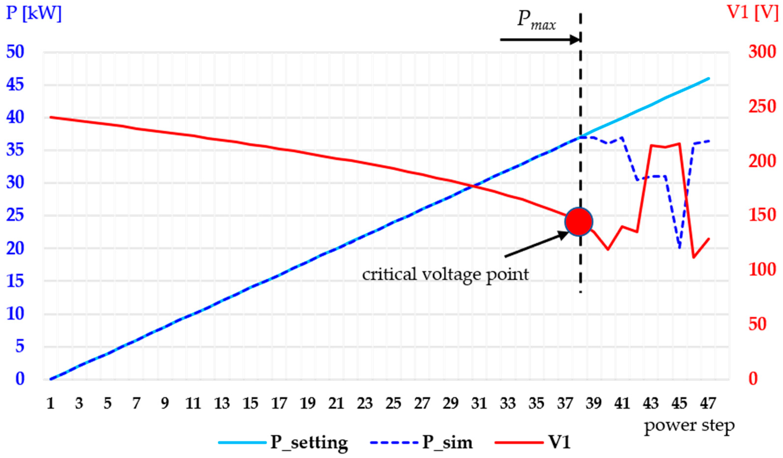
Figure 3 shows the voltage (at node N3) vs. active power characteristic for scenario P_ds3.2. Here,
P_setting is the power setting,
P_sim is the simulated power, and
V1 is the voltage at node N3. The load power at node N3 is gradually increased until convergence problems are reached. This occurred for a load power of 37 kW, which corresponds to a voltage at node N3 equal to 176.4 V. The difference between the setting power and the simulated power stems from the fact that when a convergence problem is identified, OpenDSS changes the load model from a PQ type to an impedance type. This helps the mathematical convergence to extend beyond a point of critical operation from a physical point of view.
In the dynamic simulation, the load is suddenly connected or disconnected to test the SST behavior of maintaining the voltage stability. Using OpenDSS, the point of stability limit was reached at a steady state. A 24 kW additional load is switched on at node N3 by switching on the load Ld3.2, in addition to the steady-state load of 6 kW (load Ld3.1), which results in a total load of 30 kW at node N3, which is acceptably near to the collapse value around 37 kW.
Let it be noted that the topology and parameters of the microgrid have been specifically chosen to be able to demonstrate limit situations, while also being credible for a low voltage network in terms of topology and power.
4. Grid Functionality Scenarios in Microgrids with Inverter-Based Energy Sources
In this section we define meaningful operation scenarios to emphasize the advantages for both the main (external) grid, for which the microgrid is seen as a constant load (thus fully predictable), and the SST-connected microgrid, which acts as a totally independent microgrid (by design). Simulation cases based on these scenarios are then presented and discussed.
The purpose is to show that the microgrid remains stable after important disturbances. Furthermore, it is demonstrated that the capacitor placed on the DC bus of the SST is responsible for maintaining the microgrid stability. The amount of energy available in the capacitor (CDCbus) is essential for supporting the voltage during transients. The energy stored in the SST’s battery is used to recover the DC bus voltage by injecting additional current into the DC bus, thus discharging the capacitor during transients and keeping it charged when the DC voltage is around the set-point during stable conditions.
The following timeline scenarios have been considered:
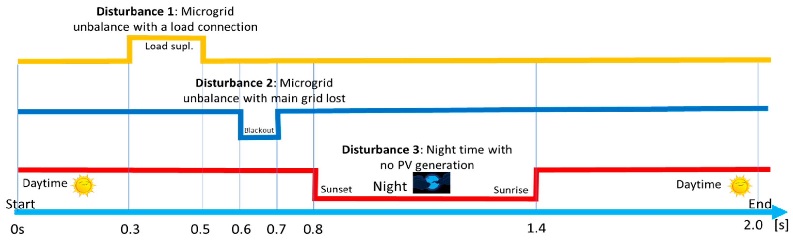
Scenario 1: In this scenario, the SST is tested in three different disturbances: the supplementary load is connected at node N3 in the time period [0.3, 0.5], in seconds (disturbance 1); microgrid unbalance due to main grid power loss in the time period [0.6, 0.7] (disturbance 2, by losing 35 kW during this period); and night period, when there is no PV production contribution, which is simulated during the time period [0.8, 1.4] (disturbance 3) (
Figure 4). The PVs have been simulated with a simplified power injection control and do not include local voltage control loops (to be subject of later studies). All disturbances have been applied as step changes, in order to achieve the heaviest operating conditions for the SST DC busbar. The scenario is also shown in
Figure 4 and is labeled as TLS1.2s (timeline scenario 1, in a 2 s time frame).
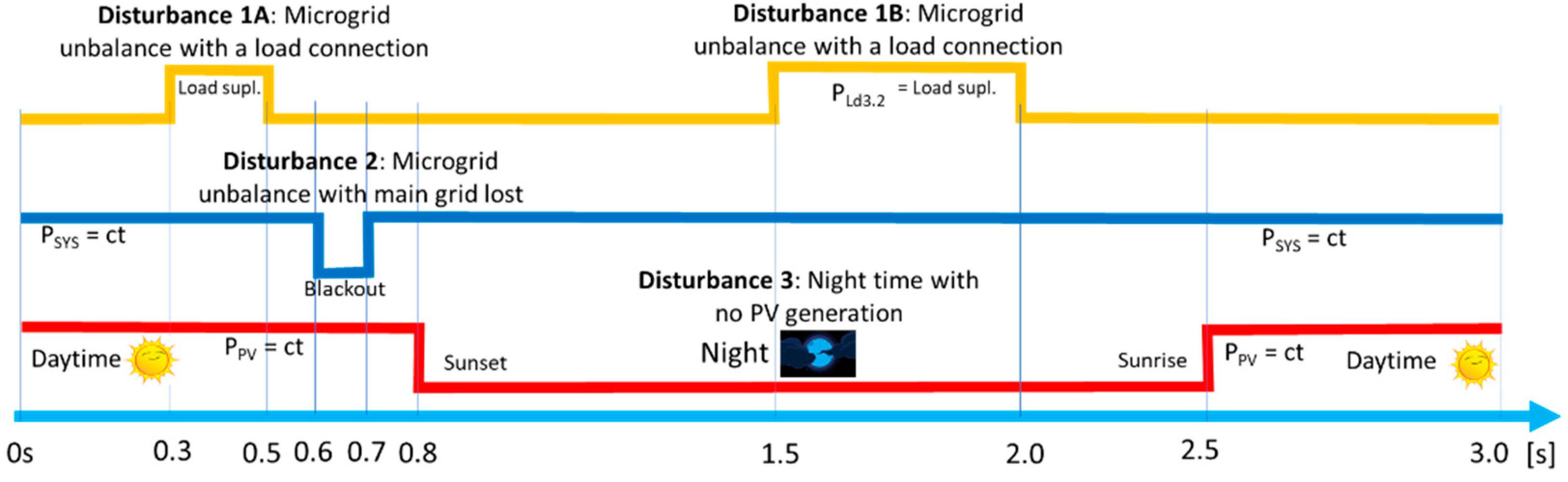
Scenario 2: In this scenario, the SST is tested with the same disturbances like in Scenario 1 —however with a superposition of two of the disturbances and on a longer time period for the additional loads connected at node N3 in the time period; [0.3, 0.5] for disturbance 1A and; [1.5, 2.0] for disturbance 1B. Microgrid unbalance due to main grid power loss occurs in the same time period [0.6, 0.7] (disturbance 2, losing 35 kW injection from the main grid) and night period, when there is no PV production, which is simulated during a larger time period [0.8, 2.5] (disturbance 3, all PV power is lost). The scenario tests even more difficult conditions for the SST as a grid-former on a longer time frame, which may show instability conditions for the DC voltage, with effects on the AC microgrid voltage. The scenario timeline is depicted in
Figure 5 and is labeled as TLS2.3s (timeline scenario 2, in a 3 s time frame).
Scenario 3: In this scenario, the SST is tested on a longer time frame on a reduced scheme of the microgrid due to simulation hardware limitations, while disturbances are simulated by means of a switchable load connected at node N0 in addition to the fixed load Ld3.1 (
Figure 6).
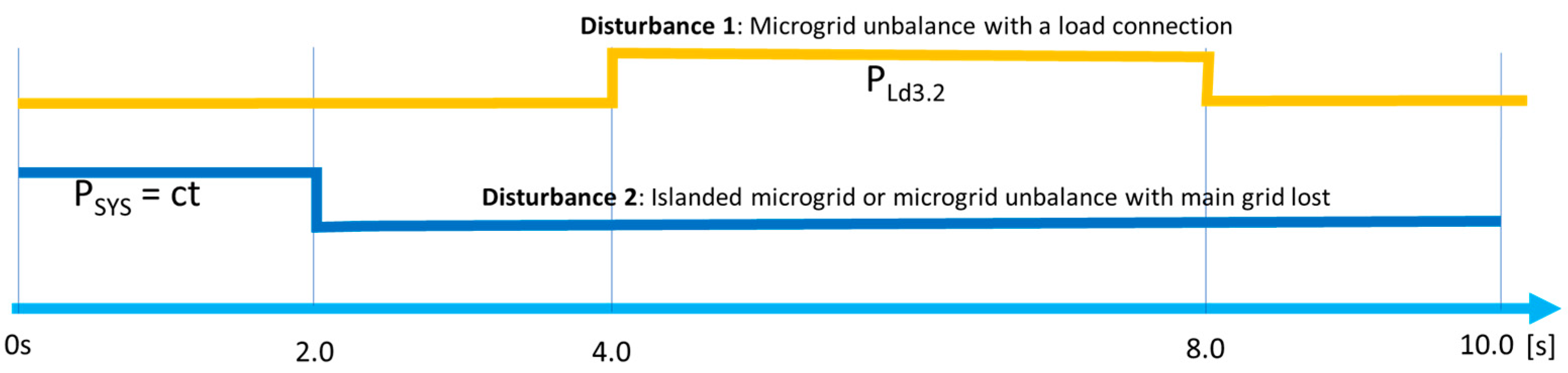
This scenario assumes a superposition of two disturbances (
Figure 7): (
i) the load Ld3.2 is connected in the reduced AC microgrid in the time period [4.0, 8.0]; (
ii) the connection with the main grid is lost instantly at 2 s under the hypothesis of a blackout in the main grid. The scenario is intended to analyze the SST’s capability to stabilize the microgrid on a longer term in case of an unbalance during the islanded operation. This scenario is labeled as TLS3.10s (timeline scenario 3, in a 10 s time frame).
The scenarios are treating different aspects of the SST functionality in serving the AC microgrid.
5. Description of the Control Structure of the SST
The simplified control scheme of the SST is illustrated in
Figure 8 together with the one-line diagram of the SST transformer. The control is focused on the DC bus voltage as well as considering the stabilizing effect of the DC capacitor, depending on the capacitance of
CDCbus.
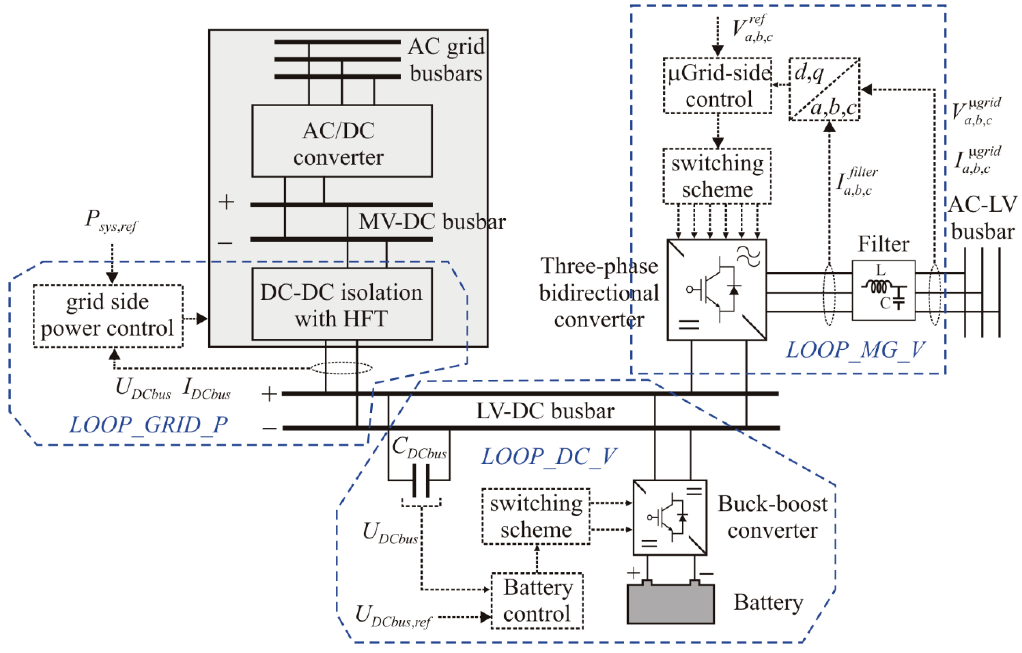
The control scheme consists of three independent loops:
- -
The control loop on the main grid side (LOOP_GRID_P)—the rectangle filled in grey—is performed in a specific way to ensure constant power exchange between the main grid and the low voltage DC bus of the SST. This loop is out of the scope of the paper, and is therefore modelled as a power-controlled source, with a constant power Psys injected into the LV DC bus of the SST.
- -
The control loop on the microgrid side (
LOOP_MG_V), aiming at controlling the three-phase bidirectional inverter topology, ensures that the voltage at the connection point with the AC microgrid is maintained stable around the reference value
Vref. This is the main control loop of the microgrid, making the SST act as a grid former as well as a “slack bus”. SST injects active power into the microgrid when the voltage drops, and absorbs active power when the voltage is above the reference value. The operation of this loop influences the voltage of the LV DC busbar, which is independently controlled by the third loop described below. In fact, the same inverter topology works as inverter from DC to AC and as converter from AC back to DC busbar, based on control logic of power switches. Therefore, the whole can be named a converter (as presented in
Figure 8). However, in the paper the term of inverter or inverter topology is used generically; in generation mode it is an inverter and it keeps the inverter topology—no matter the regime. We preserve more clarity in the paper as well by using the name of the converter for the DC/DC part.
- -
The LV DC voltage control loop (
LOOP_DC_V) aims at controlling the LV DC capacitor voltage by acting on the current injected or absorbed by the battery through its buck-boost converter (
Figure 8). Maintaining the DC bus voltage around a predefined value is essential for the performance of the three-phase inverter, which provides the AC microgrid voltage.
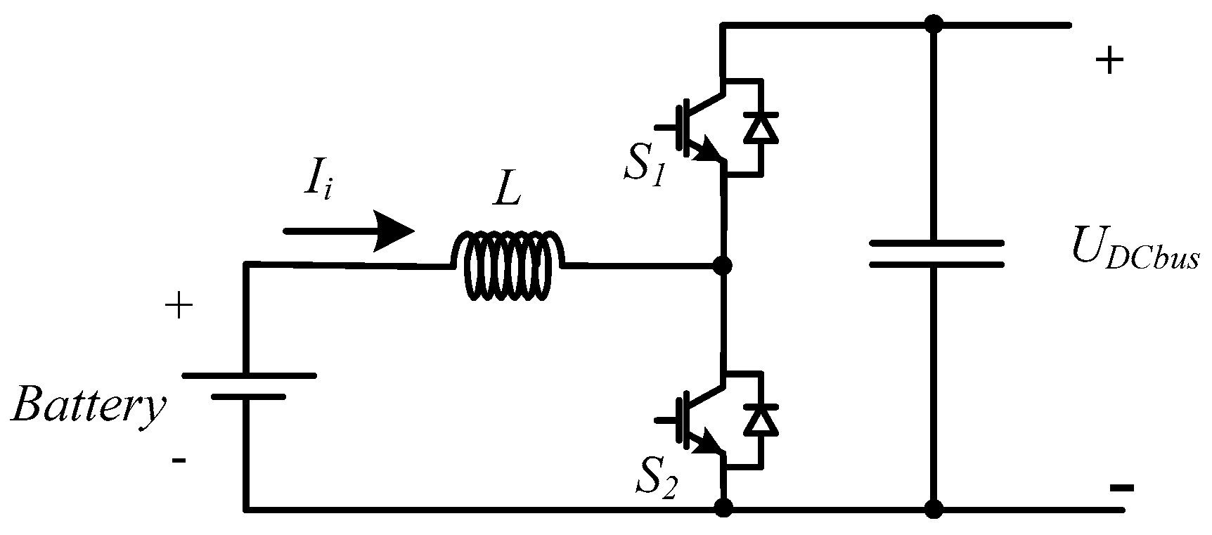
The classical bidirectional Buck-Boost topology was adopted for the DC/DC converter of the storage system, as shown in
Figure 9. The latest control loop designed to control the power converter of the storage system, includes two controllers in a closed loop connected in a cascade. The inner loop is a hysteretic current controller. The variable under control is the current in the inductor of the DC/DC converter. So, if it is required to charge the capacitor of the busbar, then the current reference will be positive, which in this case of the bottom switch (S
2) will be controlled (the other will be in off mode). If it is required to discharge the capacitor, the current reference will be negative, by which in this case will be the upper switch (S
1) that will be controlled. The output voltage of the converter is
UDCbus. Since this voltage must be maintained stable around the reference value, a voltage controller for the output of the battery converter is used. The dynamics of the converter input current is fast, while the dynamic of the converter output voltage is slower. Thus, for this latter controller a proportional-integral (PI) compensator is adopted. The output of the PI controller provides the reference for the current controller.
Figure 10 shows the scheme of the global power converter control. The battery is used as a support to maintain the voltage of the DC busbar at the desired reference value. This will be achieved by charging and discharging the battery. In order to ensure that the capacitor of the DC busbar will charge and discharge in a fast way (to maintain its voltage at the reference value), the storage system is controlled to act as a current source. Therefore, the charge and discharge of the battery is done in the current mode. The constant voltage mode cannot be considered in such a system since the battery is used to support the bus voltage, and in that mode, it cannot reach its goal.
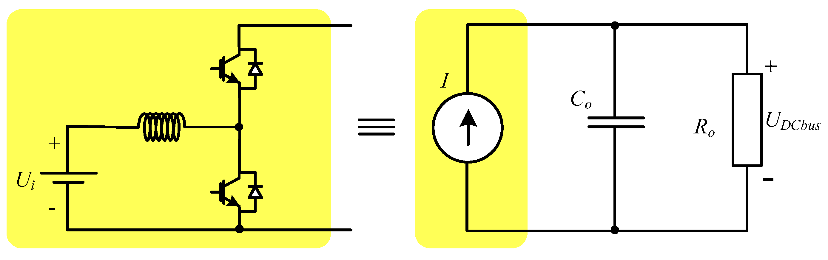
In order to determine the parameters of the PI compensator, a simplified (equivalent) circuit is considered (
Figure 11), in which the hysteretic current controlled DC-DC converter can be considered as a current source. In this way, this current source can be described by the following equation:
where
KIconv is the current gain of the converter, and
td is the delay of the current source (when there is a sudden change in the reference of the current the response of the system is limited by the switching frequency and inductor).
The gain
KIconv can be determined considering that the DC-DC power converter is conservative (input power equals the output power). Thus, we get:
where
Ui and
UDCbus are the input and output voltages of the DC-DC converter, respectively.
The voltage at the capacitor terminals
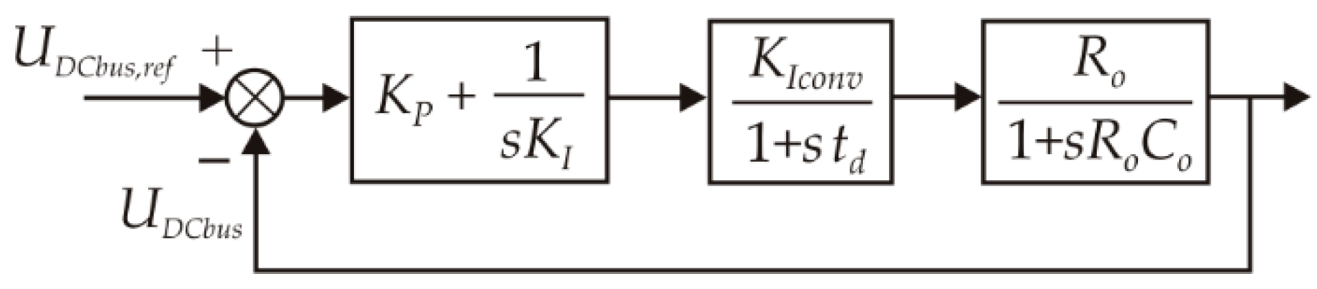
CDCbus (output voltage of the converter) is a function of the current injected by the battery (input current of the converter). This way, the output voltage of the converter is controlled through the change of the input current of the DC-DC power converter. Therefore, the closed loop diagram, which also includes the PI compensator, can be obtained as shown in
Figure 12.
Considering that the pole of the load function is cancelled by the zero of the PI compensator and that the required damping factor of the second order system is
, the following parameters are obtained:
The variation of the DC voltage is proportional to the charge exchanged, which is:
where UDCbus(t0) and UDCbus(t1) are voltages on the DC busbar at instants t0 and t1, ΔQDCbus is the total charge exchanged by the capacitor with the DC busbar during the time interval from t0 to t1, and i(t) is the current exchanged by the capacitor with the DC busbar at any instant t.
The electrical charge exchanged by the LV DC bus capacitor is the sum of all charges exchanged with the main grid, with the battery, and with the microgrid, i.e.,:
In terms of currents, expression (11) becomes:
where the main grid variables,
Psys(
t) are represented by
Psys,ref in
Figure 8 and
UDCbus(
t) is
UDCbus in the same figure, and are input to
LOOP_GRID_P;
iBat is controlled by
LOOP_DC_V, and
iMG is controlled by
LOOP_MG_V. The three loops are marked by blue polylines in
Figure 8. Note that, in the latest control loop the battery simulation is represented by a capacitor
Cbat having a much higher value than
CDCbus.
We assume that PSys(t) is constant, as the interaction with the main grid is stable and thus fully predictable on the main grid side. The control loop LOOP_DC_V is practically regulating the voltage of the DC busbar by controlling the current iBat(t), in both steady-state and dynamic exchange of current iMG(t). Thus, the microgrid—and consequently the power on the LV AC side of the SST—is controlled independently by LOOP_MG_V.
When the PSys setpoint is changed, e.g., to zero, the control loop LOOP_DC_V is still only regulating the voltage of the DC busbar. Thus, the voltage may be influenced by the additional dynamic change of PSys. It is therefore essential to define a normal operation band of voltage values on the DC bus that ensure microgrid functionality.
6. Numerical Simulations
This section presents the results and comments of the dynamics of relevant parameters—especially the DC bus voltage of the SST. We first focus on choosing the DC bus voltage setpoint, UDCbus. An optimal value of 1200 V is proposed, with a normal operation range between 1000 and 1400 V, which ensures that the SST has the role of “grid-former” for the microgrid. In other words, any value inside this range would allow maintaining a 230 V rms voltage at the AC terminals of the SST.
To determine the acceptable DC bus voltage band that guarantees normal voltage in the AC microgrid, we have performed a reasonable number of simulations on the proposed MDA. Stable operation was obtained for DC bus voltages higher than 1000 V DC.
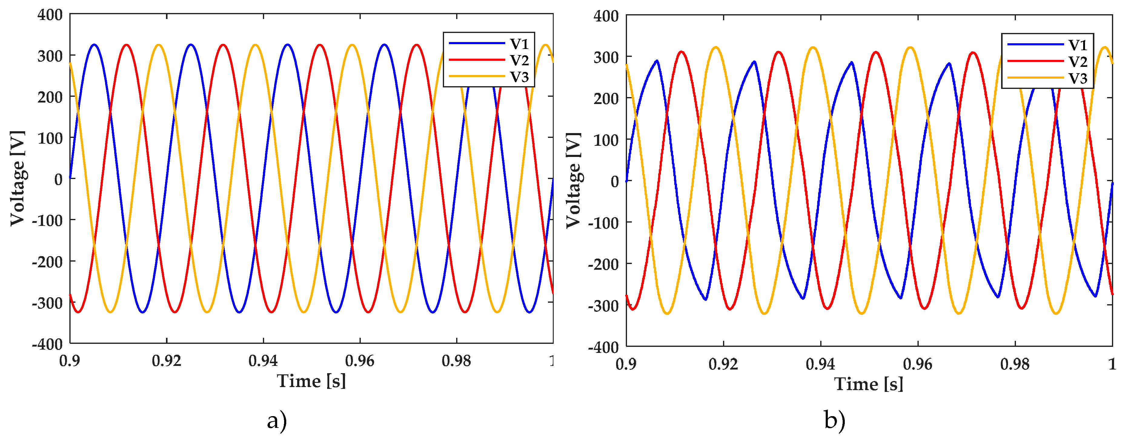
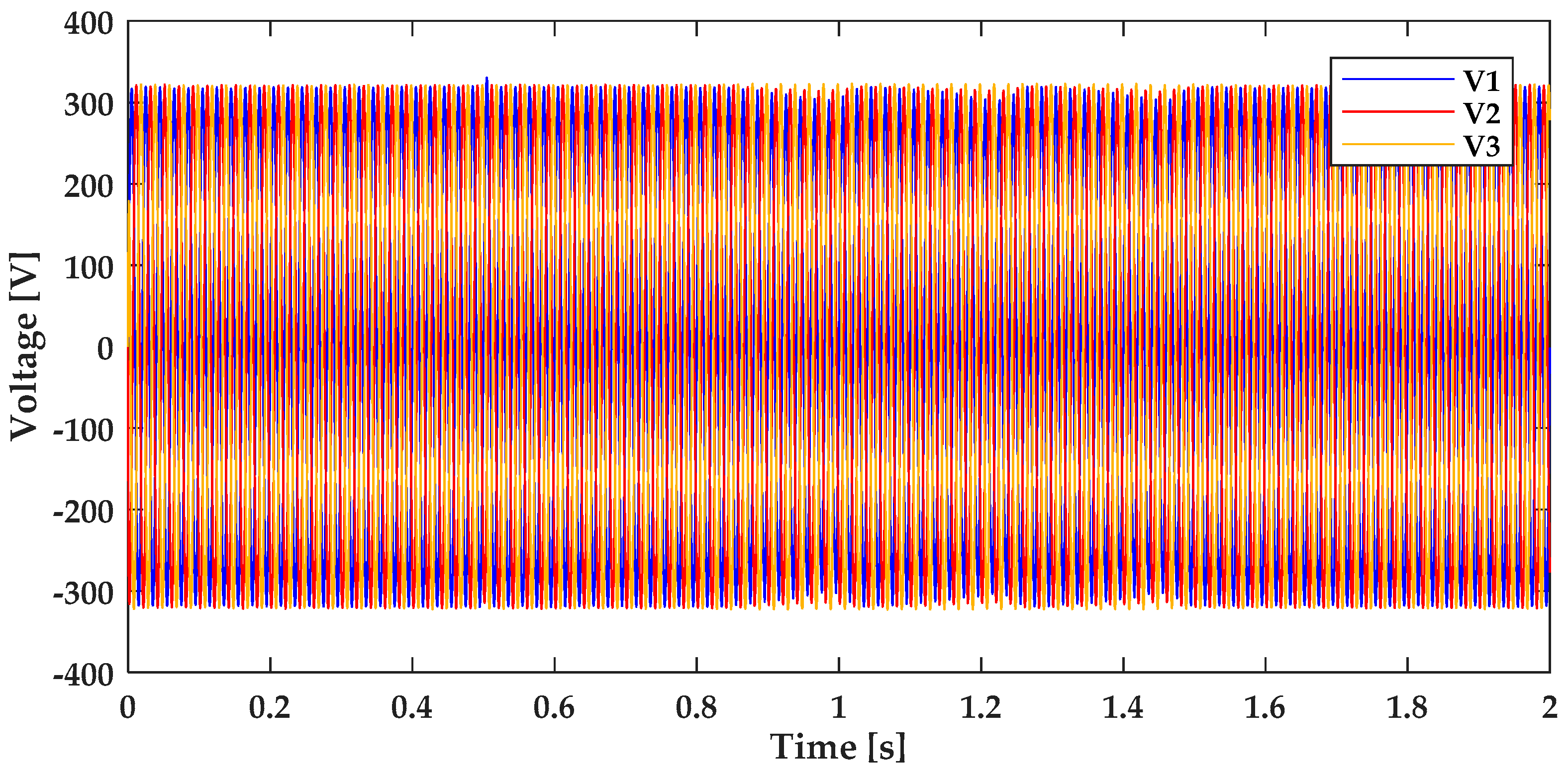
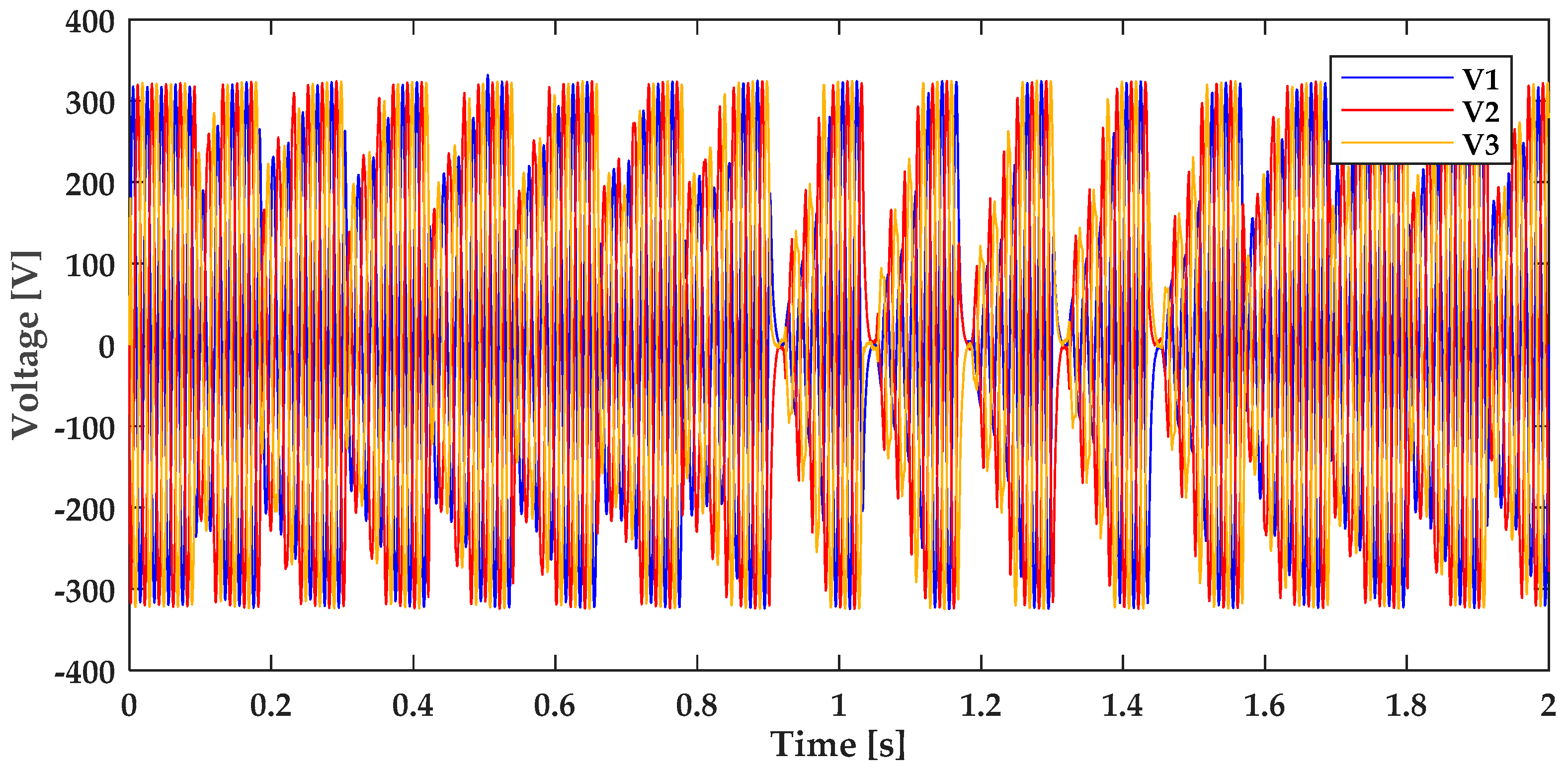
Figure 12 shows how DC bus voltages can influence the AC voltages in regard to their waveforms. The 1200 V setpoint is the most appropriate for accurate voltages (
Figure 13a), while a 900 V DC causes asymmetric and unstable voltages on the AC microgrid side (
Figure 13b). The problem of that is verified in the last figure as the maximum output voltage must always be lower than the DC busbar voltage. On the other hand, the minimum value of the DC busbar to ensure the desired AC voltage is also a function of the required power. At the L filter, there is a drop voltage that is dependent of the current through that inductor. Thus, the definition of the minimum DC voltage bus level must be a function of the maximum required power, which should be higher with the increase of the required power. To ensure a robust and stable AC voltage at the terminals of the AC capacitors filter, it was used as a voltage sliding mode controller [
42]. This controller is based on the αβ vectorial voltage modulator [
43]. When the DC voltage level is insufficient, the amplitude of all voltages are not completely equal; this is because the maximum amplitude that is achieved in accordance with each of the axis is different. So, from
Figure 13b it is possible to verify that the 900 V level of the DC busbar voltage is not high enough for the controller to maintain the AC voltages with very low distortions.
Based on these observations, it has been considered that the AC grid voltage waveforms are healthy if a smaller and safer band for UDCbus is chosen, eventually in the interval [1000 V; 1400 V], which is a safer range. In this context, for testing the dynamic stability on the microgrid side, a large load or generation disturbances have been chosen on the AC side, but with magnitudes lower than the load values which are near the voltage stability limit in the remote node N3 of the microgrid.
The voltage range of UDCbus in the interval [1000 V; 1400 V] was tested for the three types of disturbances:
Losing the main grid supply (35 kW in our tests)
Connecting an additional load in the AC microgrid, at the far end, still within the voltage stability range, according to the previous section, which is chosen to be a three-phase load of 24 kW at nominal voltage of 230 V AC;
Losing entirely distributed PV production, which is about 70 kW at nominal voltage.
All these simulations have been performed in Simulink (version 2017b), and the simulation results are presented as follows.
Lower set-points for the UDCbus cause progressive instability in generating normal three-phase voltages at the PCC of the SST.
The sets of tests presented below have been made in order to analyze the following aspects:
- -
The microgrid dynamic stability was performed for different values of the capacitance CDCbus, and the limit values for this capacitance that ensures stability was identified. For this, the TLS1.2s scenario is used.
- -
A correlation between the mechanical inertia
H, specific in the synchronous grids and the electrostatic inertia provided by capacitors placed on the DC bus behind the inverters (
Table 1).
- -
For a value of CDCbus near the stability limit, we analyze the influence of PI controller parameters KP and KI on the DC bus voltage dynamics; the more complex TLS2.3s scenario is used for this purpose.
- -
For a value of CDCbus that ensures the safe operation of the microgrid, a longer-term control is analyzed. For different values of the PI controller parameters, the TLS3.10s scenario is used.
- -
The independency from a particular frequency operated in the microgrid is analyzed.
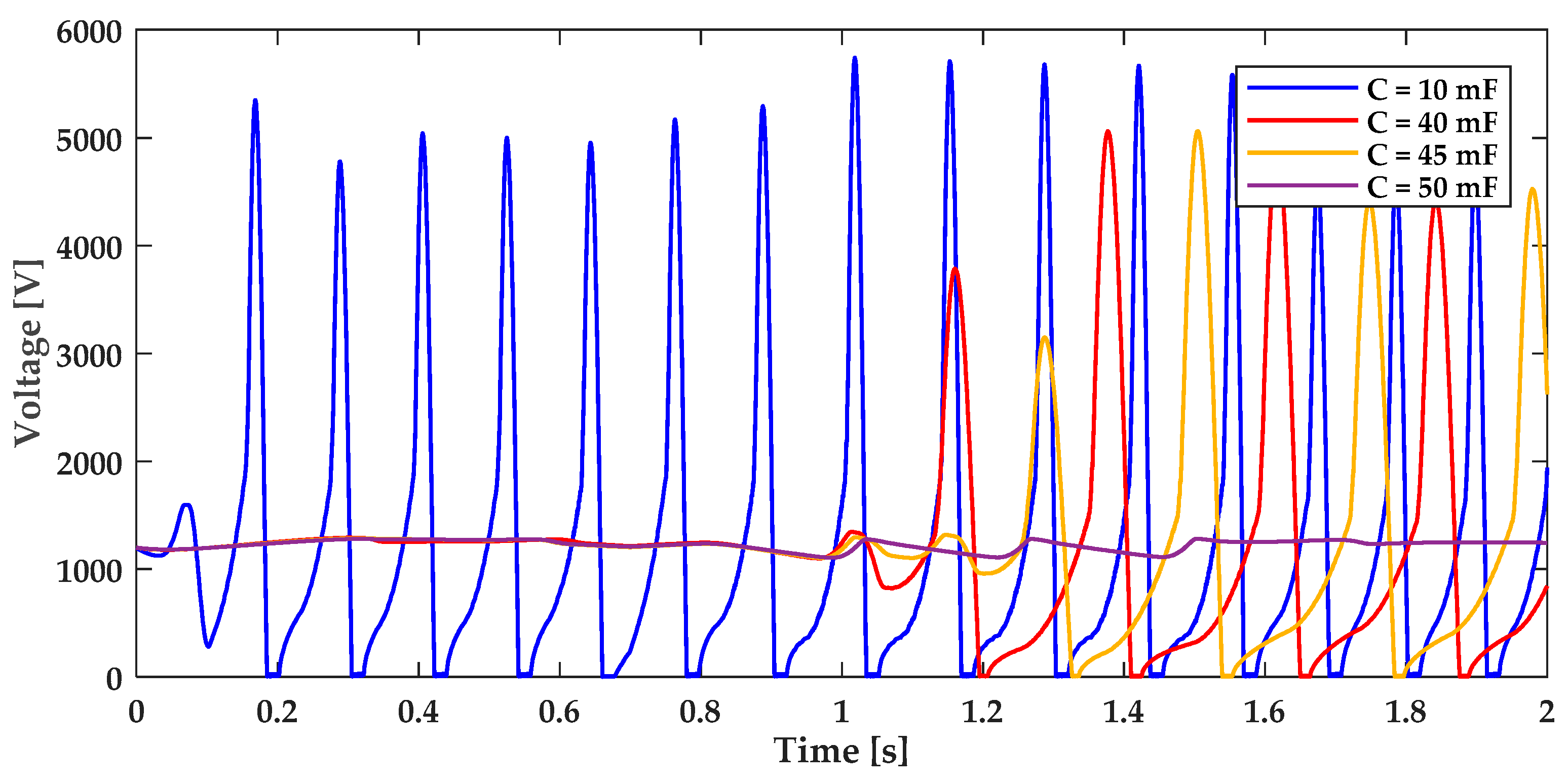
As listed above, the first essential goal was to find the limit value of CDCbus. We performed tests for a range of values from 10 to 1000 mF.
TLS1.2s: the first set of tests is intended to study the voltage stability at the SST’ PCC with the microgrid by analyzing the stability of the SST DC voltage.
For the range between 10 and 50 mF, it has been found that values between 10 to 45 mF causes DC bus voltage instability, as can be seen in
Figure 14.
Other parameters used in this simulation were: Cbat = 10 F (up to 1000 times higher than the capacitor on the DC bus), KP = 0.25 and KI =0.25. The 50-mF value of the capacitor ensures acceptable voltage values between 1000 and 1400 V; this case is developed in more detail in the next set of tests.
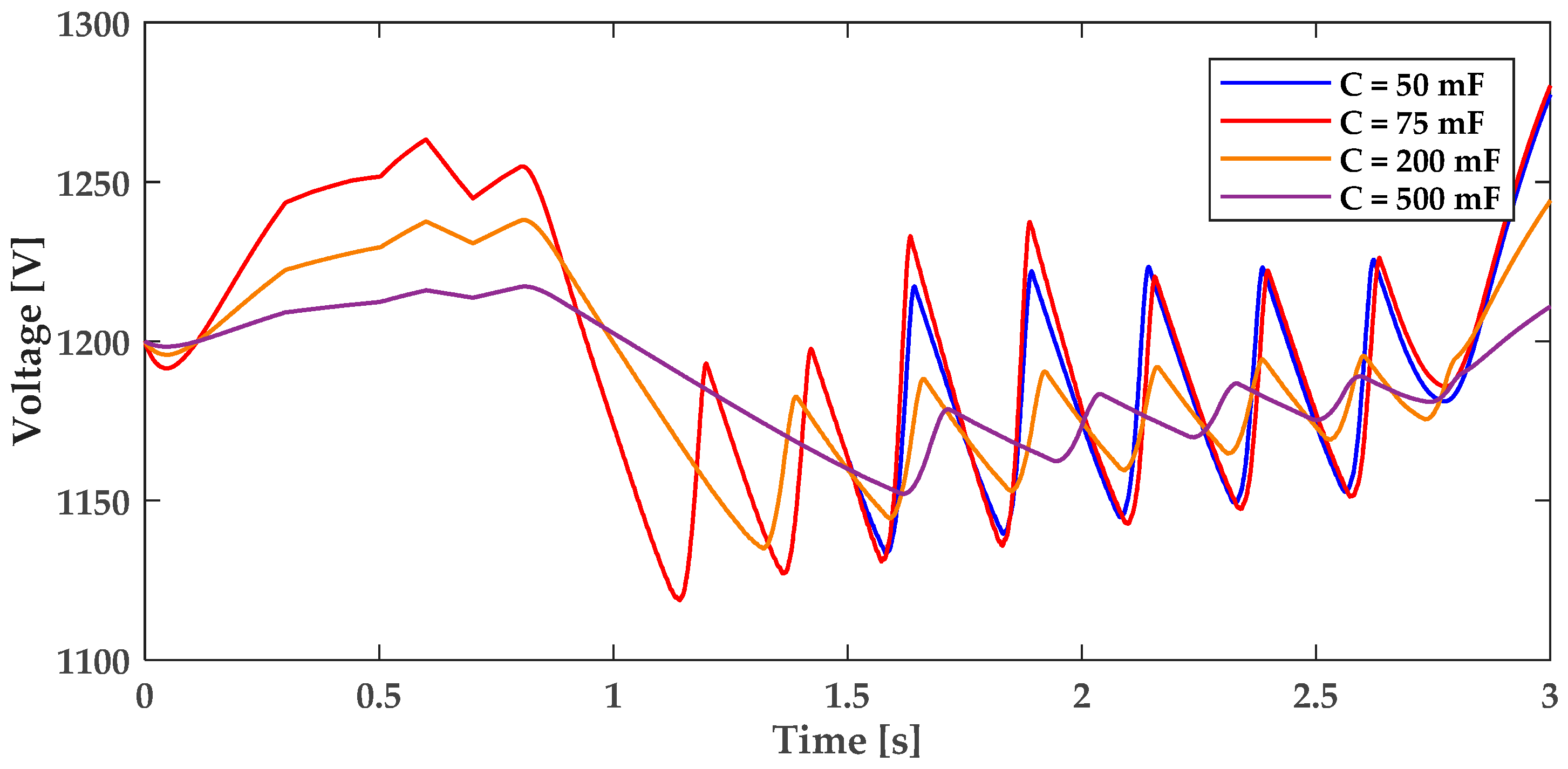
TLS2.3s: The next set of tests assumes capacitor values in the interval [50 mF; 500 mF].
Figure 15 reveals that bigger voltage deviations are experienced for a capacitance of 50 mF, whereas a capacitance value of 500 mF improves the voltage stability.
A relevant aspect to be analyzed when considering the capacitor as a source of “inertia” for the microgrid is the capacitor’ energy.
In frequency dependent grids, the kinetic energy can be deployed in seconds. It means the time needed to consume the rotating inertia energy at the total load of the grid. Usual values are
H from 1 to 7 per unit seconds (e.g., 6.3 s for nuclear units down to 3 s for conventional hydro and 1 s for small hydro, as per [
44], while earlier studies show, e.g., that Japanese systems had an inertia constant of 14 to 18 s [
45]). For the former, it is assumed that the energy is provided by all rotating machines, while in due time the primary frequency control loop is activated to contribute to the frequency recovery. The disturbance can be seen in the rate of change of frequency (RoCoF), which should be up to a few Hz/s to ensure the system stability.
In microgrids, with inverter-based energy resources only, the electrostatic energy of the DC busbar’s capacitor of the SST (and with contribution from other elements in the microgrid having DC buses behind inverters) is released somehow similar to the kinetic energy, as a reaction to voltage variations, thus contributing to voltage stability. Thus, the energy of the capacitor is essential in understanding the dynamics of the microgrid and the stability limits.
Table 1 shows the energy stored in the DC capacitor for various values of the capacitance
CDCbus, and the equivalent energy extracted when the voltage decreases from the optimal value of 1200 V, to 1100 V—a value which still ensures the stability in the microgrid. In order to provide the necessary electrostatic energy in extreme conditions, the DC voltage can be reduced to 1000 V, but accepting abnormal operating conditions.
Let us consider the expression of the energy stored in the capacitor given by Equation (3), where
E1200V is shown in
Table 1 for
UDCbus = 1200 V and calculated for several values of
CDCbus.
The energy released by the capacitor, when the DC voltage reduces from 1200 V to 1100 V, is calculated as:
which is marked as Δ
E2
c in
Table 1 and calculated for several values of
CDCbus.
A similar formula applies for a capacitor in discharging mode, where voltage drops from 1200 to 1000 V. It is denoted as Δ
E3
c in
Table 1 and calculated for the same values of
CDCbus.
In order to obtain an equivalent for
H, we calculate the time needed to extract the full capacitor energy at nominal power of the SST, which is considered
SN = 100 kVA, with the maximum effect when only active power is drawn, which is
P = 100 kW. We therefore have the following equation for the extraction of the entire energy of the capacitor:
which is marked as
T1
100kW in
Table 1 and calculated for each
CDCbus value.
As the energy can be extracted from the capacitor only until the capacitor voltage reaches a certain minimum value, we consider this value equal to 1000 V (as shown before to keep the AC microgrid operation stable). Additionally, we calculated this energy for a more restrictive voltage value of 1100 V. We obtain a “practical” time for each of these limits as being
T2100kW for 1100 V limit and
T3100kW for 1000 V limit:
In power-electronic applications using a battery with a reaction time of up to 100 ms (equivalent to the primary reserve for voltage levels on the DC bus) the values for T2 and T3 show a comparable time, for “deploying” the 1200 to 1000 V energy, which is more similar with the dynamics in the main power systems. For instance, by choosing CDCbus = 500 mF, the inertia constant in the microgrid driven by the SST, is HC2 = T2100kW = 1.1 s, and it can be increased to HC3 = T3100kW = 2.2 s if CDCbus is 1 F.
A real implementation of such capacitor values would require the supercapacitors (SC) technology, which are usually around 20 to 30 times more costly than Li-Ion batteries for the same kWh capacity. A quick calculation shows that the ratio between the necessary SC and an ordinary battery to support the SST mission of balancing the microgrid over a longer period, e.g., four hours, does not require much higher costs than the investment in the battery itself. For this, we compare the energy from a CDCbus = 1000 mF capacitor, which is shown in the table as EC = 720 kWs = 0.2 kWh, with the energy of a Li-Ion battery. This needs to be equal to EBat = 400 kWh in order to support four hours of microgrid control with the SST at full nominal power (e.g., SN_SST = 100 kVA, while the ratio 4:1 between energy and power is now usual for new storage applications), which leads to a ratio of 400/0.2 = 4000. With SC energy 20 times more costly, the price increase of the mixed Li-Ion battery and the SC, (for providing the necessary “electrostatic inertia”), is only 20/4000 = 0.5% of the total storage investment. This means that the relatively high value of the CDCbus supercapacitor is negligible in the overall budget. However, it ensures the necessary dynamic stability of a microgrid with inverter-based energy resources only.
The next set of simulation tests is intended to determine the best values for the PI parameters (KP and KI) from the LOOP_DC_V control loop.
Figure 16 shows the voltage dynamics for two values of
CDCbus (= 40 and 46 mF) and with the selected values for
KP and
KI, using capacitors at the limit of dynamic stability, in a TLS1.2s scenario.
Figure 16 shows a better control of
LOOP_DC_V for
KP = 0.25, and
KI being either 0.25 or 0.125. The set of tests shows that there is a range of PI parameters which keep the voltage control stable. This includes the smaller capacitor values of
CDCbus = 40 mF, which ensure stability for PI parameters
KP =0.125 and
KI =0.125. As a comparison, the value of
CDCbus = 40 mF resulted in voltage instability for
KP =0.25 and
KI =0.25, as has been previously shown in
Figure 14.
Still the boundary around CDCbus = 50 mF can ensure stable operation for higher values and unstable operation for lower values.
For more clarity, besides the voltage level of the DC busbar, additional data is examined at the SST point of common coupling with the microgrid, as waveforms in typical stable operation, e.g., for scenario TLS1.2s, in
Figure 17 and
Figure 18.
For comparison purposes, the voltage variation in the most unstable situation, using a capacitor of only
CDCbus = 10 mF in the same TLS1.2s scenario, is depicted in
Figure 19.
The voltage at the AC side of the SST remains stable no matter the disturbances on the AC side (the change of charge / discharge status for the battery and the loss of main grid power).
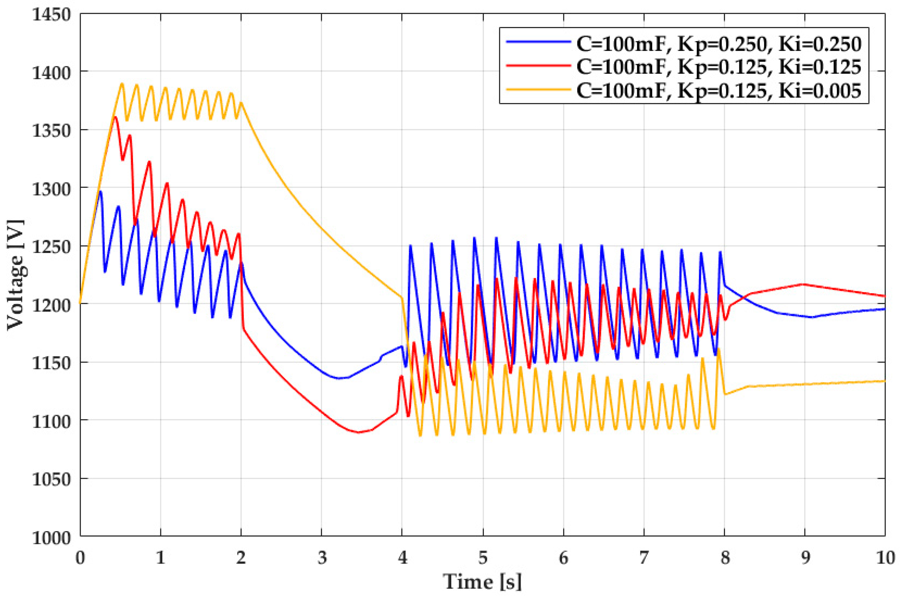
TLS3.10s: a third set of tests was performed to study the DC bus stability on longer terms, which in this case was 10 s, assuming
CDCbus = 100 mF and different values of the PI parameters of
LOOP_DC_V control loop, as shown in
Figure 20.
This set of scenarios shows an acceptable stable evolution of DC bus voltage in the range between 1050 and 1400 V, which has been considered as ensuring stable AC microgrid forming.
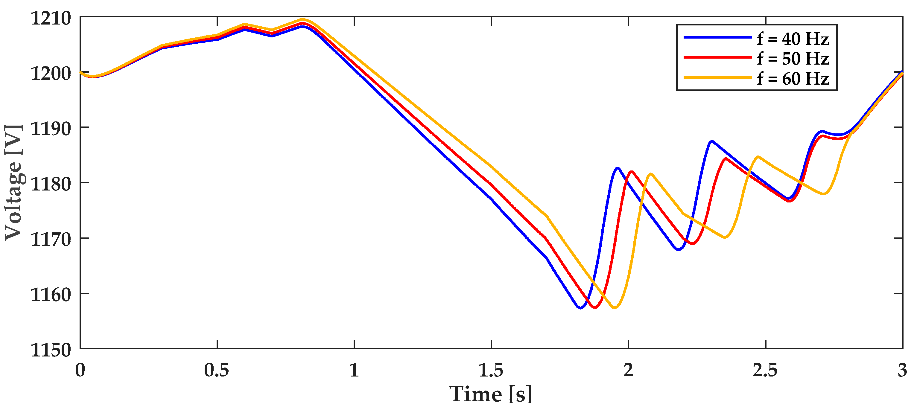
TLS1.2s-f: A final set of tests is related to frequency of the microgrid and is performed under the conditions of scenario TLS1.2s but is denoted as TLS1.2s-f. It has already been inferred that the grid frequency is no longer important and that the grid can work at any frequency in a range that is still acceptable for the loads. In this work we are also testing this feature by performing simulations for three values of the frequency: 50 Hz, as a nominal value in Europe and some other regions; or 60 Hz, as a nominal frequency in the USA and some other regions; and 40 Hz, which is no longer used in power systems, but has some historical backgrounds.
Figure 21 shows the evolution for
UDCbus for microgrids working at 40, 50 and 60 Hz, with the described disturbances in the microgrid.
This figure shows that the balancing in the microgrid and the AC grid stability principles driven by the SST DC busbar are similar for different microgrid frequencies. Note, however, that this does not mean that the frequency cannot be changed. The reason has nothing to do with the natural control due to any rotating speed, but it is only a signal to the grid participants that may be used for droop control strategies.
7. Conclusions
In this paper the authors are extending the investigation on microgrids by design architecture (MDA) with inverter-based generators only, by employing an SST as interface with the main grid. Under the proposed conditions, the work aimed at evaluating the importance of the electrostatic energy inertia (ELEI) for the voltage stability, while demonstrating through simulations that the frequency is no longer important in asynchronously interconnected AC microgrids relying on inverted-based energy resources (IbER) only. An analogy between mechanical inertia and electrostatic inertia was shown in the theoretical part of the paper.
Different timeline scenarios (TLSs) and specific tests have been chosen, with emphasis on the DC bus voltage stability inside the SST. As the AC microgrid stability is mainly related to a voltage stability problem, the disturbances applied to the SST have been made so that they are approaching the voltage stability collapse in the AC grid. This aspect has been investigated both theoretically and within numerical simulations, with a set of OpenDSS load-flow calculations.
The simulations have shown the dependency of the SST and the microgrid voltage stability on the CDCbus values, considering a range from 10 to 1000 mF, for a nominal power of the SST SN = 100 kVA (a value appropriate for the microgrid loads). The results have been obtained for values between 100 and 1000 mF, which ensure the AC microgrid stability—even near the voltage stability limit of the microgrid. The strong connection between the stability of the capacitor voltage, UDCbus, and the AC microgrid, as grid-former role of the SST, is obvious.
Finally, the role of “electrostatic inertia” of the capacitor behind the inverters is demonstrated in various situations, where power balancing is maintained without frequency involvement, but only based on voltage levels in the AC microgrid, which is sustained by voltage stability on the DC bus.
A simplified calculation also shows that the necessary value of CDCbus (in order to have similar inertia constants with the main grid generators) involves only very small additional investment in the combined battery + supercap storage system of the SST-interfaced microgrid (indicative around 1%), which shows feasibility under today’s technologies and prices.
The paper consolidates a previous proof of concept, thus paving the way for microgrids with resilience by design, based on SSTs with storage means. We showed that the stability mechanism in such microgrids is based on the DC bus voltage and sustained by the “electrostatic energy inertia” of the capacitor with a naturally occurring action (similar to mechanical inertia in classic grids, which is also naturally occurring), while other automatic controls are supported by utilizing the battery.
Future work will deal with a broader range of aspects related to the “electrostatic inertia” mechanism and in microgrids: (a) better automation for SST voltage control at the SST DC busbar by finding appropriate automation blocks; (b) study of the aggregated “electrostatic inertia” based on more than one grid-former device, compared with this study, which considered only the SST as grid-former —even if this can remain the most important contributor; (c) adding more complexity in the microgrid, such as additional voltage control loops at the different PV inverters inside the grid, which can contribute even more to the microgrid stability at its limits; (d) a more refined simulation of the battery behavior, considering technological aspects and consequent details; (e) short-circuit simulations in the AC microgrid; (f) while the presence of an asynchronous motor as an additional load in the microgrid has been briefly analyzed in one case and showed similar stability in the microgrid, scenarios with rotating machines as loads need further investigation; (g) advancing the analysis by using hardware in the loop analysis with some real components as the first step, and with an experimental real microgrid setup as the second step; (h) analyze the electrostatic inertia contribution from the PV’s capacitors on the DC busbar behind their inverters; (i) analysis for non-symmetrical loads and disturbances; (j) analysis considering non-sinusoidal situations, considering the harmonics of voltages and currents, and; (k) other studies related to resilience and microgrid optimization in the paradigm of microgrid by design, which has been considered in this paper and in our previous papers.

 ,
, 


