Article

Fault-Tolerant Control of Doubly-Fed Wind Turbine Generation Systems under Sensor Fault Conditions

College of Electronic Information and Automation, Tianjin University of Science and Technology, Tianjin 300222, China
*
Authors to whom correspondence should be addressed.
Energies 2019, 12(17), 3239; https://doi.org/10.3390/en12173239
Submission received: 6 July 2019 / Revised: 17 August 2019 / Accepted: 19 August 2019 / Published: 22 August 2019

Abstract

:
This paper studies the fault-tolerant control problem of uncertain doubly-fed wind turbine generation systems with sensor faults. Considering the uncertainty of the system, a fault-tolerant control strategy based on a T-S fuzzy observer is proposed. The fuzzy observer is established based on the T-S fuzzy model of the uncertain nonlinear system. According to the comparison and analysis of residual between the state estimation of the fuzzy observer output and the measured value of the real sensor, a fault detection and isolation (FDI) based on T-S fuzzy observer is designed. Then by using a Parallel Distributed Compensation (PDC) method we design the robust fuzzy controller. Finally, the necessary and sufficient conditions for the stability of the closed-loop system are proved by quoting Lyapunov stability theory. The simulation results verify the effectiveness of the proposed control method.

1. Introduction

With the continuous progress of social economy, humans’ demands and dependence on energy have reached the commanding heights of history, and the development of green energy has become a topic of widespread concern around the world [1,2,3]. Wind power energy as an important component of green energy has become an important force to maintain the sustainable development of global energy [4]. As a typical large-scale complex nonlinear system, the safe and stable operation of wind turbines is threatened due to their poor installation environment, which leads to frequent sensor and actuator faults, and also affects the process of extensive engineering of wind turbine generation systems. Therefore, as an effective means to improve the safety and reliability of wind power system, fault-tolerant control has become a research hotspot.
There are many kinds of sensors in doubly-fed wind turbine generation systems, and their accuracy, timeliness and reliability are very important for the stable operation of the closed-loop system. Once a fault occurs, the feedback controller can’t get the correct feedback data information, which will affect the overall control performance of the system, and even lead to complete system paralysis. In recent years, many fault diagnosis and fault-tolerant control methods for sensor faults have been put forward by experts and scholars at home and abroad [5,6,7]. In [8], a sliding mode observer is used to detect sensor faults in a permanent magnet synchronous motor drive system. For current and voltage sensor faults, fault-tolerant control strategies of closed-loop V/f and direct calculation of counter potential were proposed, respectively. In [9], a nonlinear observer is introduced for the angular rate and attitude sensor faults of the satellite attitude control system, and an integrated sensor fault detection and recovery control method is proposed. In the study of sensor faults in doubly-fed wind power generation systems, a fault-tolerant control strategy based on Kalman filter is studied in [10]. During the sensor fault period of the system, the estimated value of the Kalman filter output is used to replace the measured value of the faulty sensor, and the vector control system is reconfigured to achieve the fault-tolerant control purpose. Reference [11] studied a fault diagnosis method for the high-speed shaft speed sensors of wind turbine generation systems by designing a fuzzy T-S system sliding mode observer, but no specific control method was given to compensate the reconstruction faults.
Wind turbine generation systems are strong non-linear systems, which often show stochastic and switching characteristics under the action of stochastic and intermittent winds. In practical engineering applications, it is usually difficult to achieve the desired control effect with a controller based on a traditional linear observer. The T-S fuzzy algorithm has the advantages of simple structure and strong approximation, the model output has good mathematical expression characteristics, which can approximate almost any complex nonlinear system, hence uncertain nonlinear system controllers based on the T-S fuzzy model have been widely used in engineering [12,13,14]. In order to maximize the energy capture, a variable structure sliding mode controller (SMC) for a doubly-fed wind turbine was designed on the basis of fuzzy logic theory in [15]. A T-S fuzzy model was used in [16] to describe nonlinear systems, and a Robust Fuzzy Scheduler Controller (RFSC) was designed to achieve the stability of the system by taking into account the parameter uncertainty of the system and wind disturbance. Reference [17] also established a complete wind turbine pitch model based on fuzzy theory, and designed a fuzzy proportional-integral-derivative (PID) controller to realize real-time control of wind energy systems. However, the possibility of failure of wind energy system components is inevitable in practice, hence the stability of the system will be difficult to guarantee once a failure of wind turbine components occurs.
Here, a fault tolerant control strategy based on a T-S fuzzy observer is studied for sensor faults of doubly-fed wind turbine generation systems. Firstly, the uncertain T-S fuzzy model of a nonlinear system is established considering the uncertainty of the system. Secondly, the fault detection and isolation (FDI) based on T-S fuzzy observer is designed. The state estimation value of the fuzzy observer output is compared with the real sensor measurement values to analyze the residual. The state reconstruction of the output based on normal sensor and observer is selected by a decision module and switcher. Then, a robust fuzzy controller is designed by using a Parallel Distributed Compensation (PDC) method to realize fault tolerant control of sensor faults in uncertain nonlinear systems. Finally, the feasibility of the proposed method is proved by quoting Lyapunov stability theory, and the simulation results further verify the effectiveness of the control method.

2. Problem Description

The fuzzy rules of the fuzzy system T-S model (1) is established with sensor faults and parameter uncertainties, each of which represents one of the subsystems.
R i : If z 1 ( t )   is   F 1 i   and   z 2 ( t )   is   F 2 i and   z k ( t )   is   F k i , then:
x ˙ ( t ) = ( A i + Δ A i ) x ( t ) + B i u ( t ) y ( t ) = C i x ( t ) + F ¯ i f s ( t )    i = 1 , 2 , , r
where R i denotes the i-th fuzzy rule, z ( t ) = [ z 1 ( t )   z 2 ( t ) z k ( t ) ] T represents the premise variable, F j i stands for fuzzy set, i = 1 , 2 r denotes the total number of system fuzzy rules, j = 1 , 2 k ; x ( t ) R n is the state vector, u ( t ) R m is the control input, y ( t ) R p is the system output; A i R n × n , B i R n × m and C i R p × n represent the parameter matrices of the system respectively. F ¯ i R p × q denotes the known sensor fault matrix, f s ( t ) R q × 1 is sensor fault, Δ A i is the uncertainty real value matrix, assuming that f s ( t ) and Δ A i are norm bounded, and there are positive numbers α and β , which make inequalities f s ( t ) < α , Δ A i < β valid.
Defining fuzzy weights:
u i ( z ( t ) ) = h i ( z ( t ) ) i = 1 r h i ( z ( t ) )
where h i ( z ( t ) ) = j = 1 k F j i ( z j ( t ) ) , F j i ( z j ( t ) ) denotes the membership function of the premise variable z j ( t ) corresponding to fuzzy value. h i ( z ( t ) ) denotes the weight of rule i and meets the following conditions:
h i ( z ( t ) ) 0 , i = 1 N h i ( z ( t ) ) > 0 , i = 1 , 2 , , r 0 < u i < 1 , i = 1 N r u i ( z ( t ) ) = 1
After defuzzification the equation of state of the whole fuzzy T-S system can be given by:
x ˙ ( t ) = i = 1 r u i ( z ( t ) ) [ ( A i + Δ A i ) x ( t ) + B i u ( t ) ] y ( t ) = i = 1 r u i ( z ( t ) ) [ C i x ( t ) + F ¯ i f s ( t ) ]
Without loss of generality, in order to design the output feedback control law based on T-S fuzzy observer, the Equation (3) is transformed into the following form:
x ˙ ( t ) = i = 1 r u i ( z ( t ) ) [ ( A i + Δ A i ) x ( t ) + B i u ( t ) ] y ( t ) = i = 1 r u i ( z ( t ) ) ( I + F ) C i x ( t )
where I represents the identity matrix, F = d i a g ( f 1 , f 2 , , f p ) , 0.1 f a ( x ( t ) ) 0.1 , a = 1 , 2 , , p represents the sensor fault model matrix and considers it normally bounded.

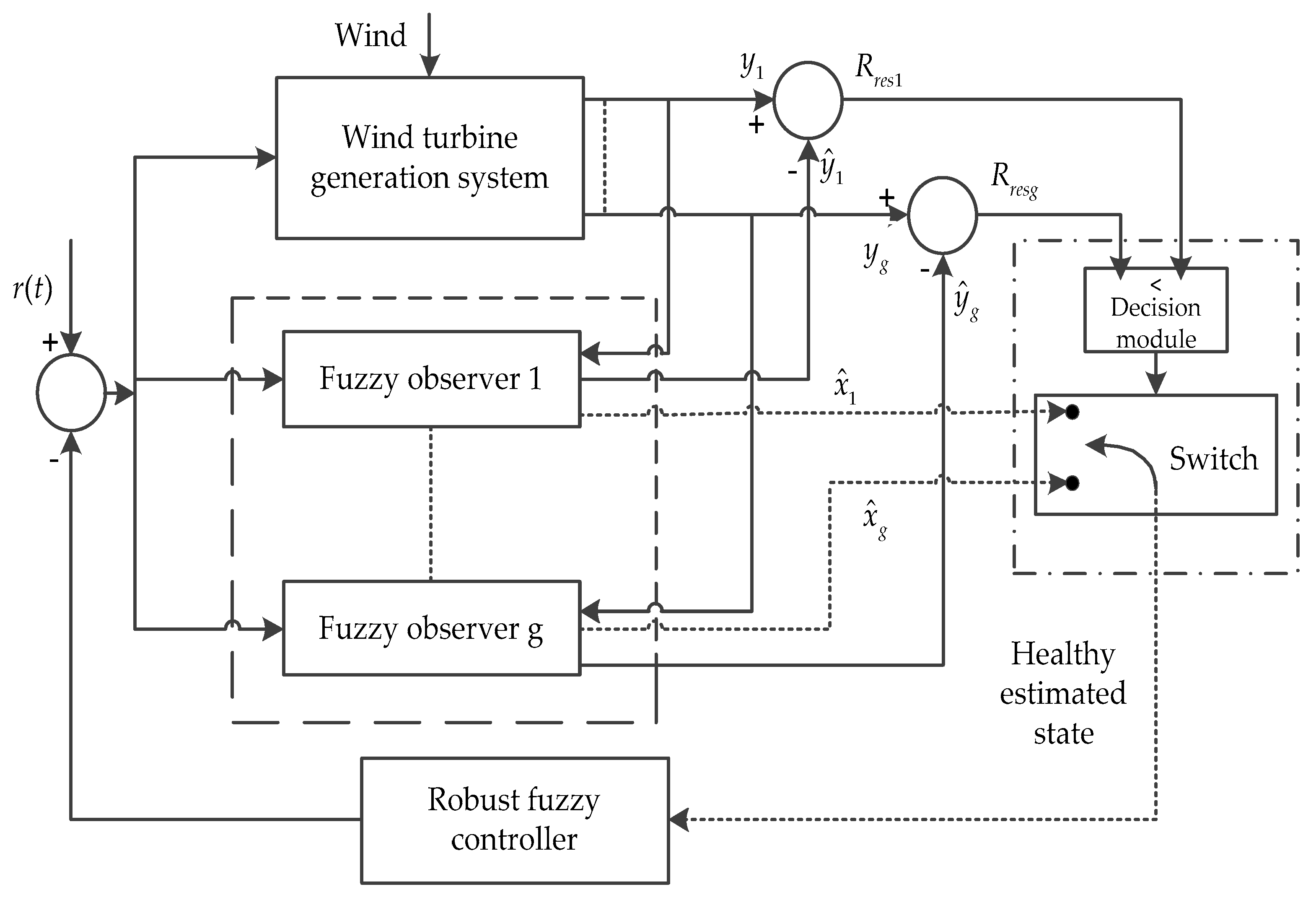
3. FDI Design Based on T-S Fuzzy Observer

Figure 1 depicts the overall structure block diagram of sensor fault-tolerant control in wind power generation system, in which the FDI based on T-S fuzzy observer consists of the following two steps:
(1)
The output residual of the system is produced according to the designed T-S fuzzy observer, and the output signal of the sensor is taken as the input signal of the fuzzy observer. Then the observation value of the observer is compared with the actual sensor output and the residual error is calculated.
(2)
The residual R r e s 1   and   R r e s g are compared with the residual threshold R t h , which are fuzzy observer1 and the output residuals of the fuzzy observer g , respectively. The logic division of the residual error is used to judge whether the system has sensor fault. Finally, the state reconstruction of the output based on normal sensor and observer is selected by the decision module and switcher.
Residual R r e s ( t ) is the measurable output deviation, namely:
R r e s ( t ) = e y ( t ) = y ( t ) y ^ ( t )
The threshold value R t h :
R t h = sup f a u l t f r e e R r e s ( t ) p e a k
Then the corresponding fault decision logic is:
R r e s ( t ) { R t h   no   sensor   failure > R t h   sensor   failure
Assuming that at most one sensor fails at any given time. If | R r e s 1 | > | R r e s 2 | , we switch to observer 2, otherwise we switch to observer 1 and so on. When the sensor works normally, the residual error affected by its noise will not converge to zero. In order to avoid false alarms, the threshold must be set large enough [18].
It is assumed that the state of the system model (1) is observable, adopting the same rule prerequisites as Equation (1) T-S fuzzy model (4) based on parameter uncertainty and sensor fault, fuzzy observer rules are as follows:
R i : If z 1 ( t )   is   F 1 i   and   z 2 ( t )   is   F 2 i and   z k ( t )   is   F k i , then:
x ^ ˙ ( t ) = A i x ^ ( t ) + B i u ( t ) + L i ( y ( t ) y ^ ( t ) )   y ^ ( t ) = C i x ^ ( t )             i = 1 , 2 , , r
where x ^ ( t ) denotes the state estimation of the fuzzy observer, y ^ ( t ) is the output vector, L i R n × 1 is the observer gain matrix. After defuzzification, the output description of the fuzzy observer is given by:
x ^ ˙ ( t ) = i = 1 r u i ( z ( t ) ) [ A i x ^ ( t ) + B i u ( t ) + L i ( y ( t ) y ^ ( t ) ) ] y ^ ( t ) = i = 1 r u i ( z ( t ) ) C i x ^ ( t )

4. Robust Fuzzy Controller

4.1. State Feedback Controller Design

The local state feedback controller based on T-S fuzzy model (4) is designed using PDC method, then the fuzzy rule for the input of the j-th controller is:
Rule j : If   g 1 ( t )   is   M 1 j   and   g 2 ( t )   is   M 2 j and   g k ( t )   is   M k j , then
u ( t ) = r ( t ) K j x ^ ( t )      j = 1 , 2 , , p
where g ( t ) = [ g 1 ( t ) , g 2 ( t ) , , g k ( t ) ] represents the premise variable, p represents the total number of fuzzy rules, K j R m × n denotes the regular feedback gain matrix, r ( t ) R m × 1 is the reference input, After defuzzification, the global state controller of the system can be expressed by:
u ( t ) = r ( t ) j = 1 p u j ( g ( t ) ) K j x ^ ( t )

4.2. Stability Analysis of Nonlinear Closed-Loop Systems

The goal of fault-tolerant control is to design the control rate so that the nonlinear uncertain system is stable and robust to some extent in the event of sensor failure.
Defining the system state observation error:
e ( t ) = x ( t ) x ^ ( t )
From Equations (3) and (8), the closed-loop equation of the system can be given:
x ˙ ( t ) = i = 1 r u i ( z ( t ) ) [ ( A i + Δ A i ) x ( t ) + B i ( r ( t ) j = 1 p u j ( g ( t ) ) K j x ^ ( t ) ) ] = i = 1 r j = 1 p u i ( z ( t ) ) u j ( g ( t ) ) [ ( E i j + Δ A i ) x ( t ) + B i K j e ( t ) + B i r ( t ) ]
where E i j = A i B i K j .
Substituting Equation (11) into Equation (5) we get:
R r e s ( t ) = y ( t ) y ^ ( t ) = { i = 1 r u i C i e ( t ) if   F = 0 i = 1 r u i C i e ( t ) + F C i x ( t ) if   F 0
Then the estimated error of state is:
e ˙ ( t ) = x ˙ ( t ) x ^ ˙ ( t ) = i = 1 r u i ( z ( t ) ) [ ( A i + Δ A i ) x ( t ) + B i u ( t ) ]           i = 1 r u i ( z ( t ) ) [ A i x ^ ( t ) + B i u ( t ) + L i ( y ( t ) y ^ ( t ) ) ] = i = 1 r j = 1 p u i ( z ( t ) ) u j ( g ( t ) ) [ ( Δ A i L i F C j ) x ( t ) + ( A i L i C j ) e ( t ) ]
Combined with Equations (12) and (14), the new fuzzy system can be arranged as follows:
[ x ˙ ( t ) e ˙ ( t ) ] = i = 1 r j = 1 p u i ( z ( t ) ) u j ( g ( t ) ) [ H i j Δ H i j ] [ x ( t ) e ( t ) ] + [ B i 0 ] r ( t )
where H i j = [ E i j B i K j 0 A i L i C j ] , Δ H i j = [ Δ A i 0 Δ A i L i F C j 0 ] .
Lemma 1: For the sensor fault system (15) with uncertain parameters, if the following matrix inequality:
μ [ T H i j T 1 ] T Δ H i j T 1 max δ ,      i , j
is true, then the system (15) is stable. Where the scalar δ is positive and denotes the robustness index, T is the symmetric matrix of proper dimensional transformation, T Δ H i j T 1 max denotes the maximum value of T Δ H i j T 1 . The proof is detailed in [19].
Let’s set the transformation symmetric matrix T = T T , P = T T . According to Lyapunov stability theory, if there is a positive definite matrix P and the control rate (10) forms the following inequality:
P H i j + H i j T P < 0 ,      i , j
is true, the fuzzy control system (4) is globally asymptotically stable.
In order to obtain observer gain L i and controller gain K j for convenience, it is assumed that:
P = [ P 11 0 0 P 22 ]
Let M = P 11 1 , that is:
M = [ M 11 0 0 I ] = [ P 11 1 0 0 I ]
Let Y j = K j M 11 , X j = P 22 L i , multiply both sides of Equation (17) by matrix M = P 11 1 to obtain the following linear matrix inequality (LMI):
M 11 A i T + A i M 11 ( B i Y j ) T B i Y j < 0
A i T P 22 + P 22 A i ( X i C j ) T X i C j < 0
Converting the inequality in the above equation into an equation, then the above inequality becomes:
M 11 A i T + A i M 11 ( B i Y j ) T B i Y j =   δ I
A i T P 22 + P 22 A i ( X i C j ) T X i C j =   δ I
By solving Equations (22) and (23), the observer gain L i ( L i = P 22 1 X i ) and controller gain K j ( K j = Y j M 11 1 ) can be easily obtained. Figure 2 describes the relationship between the uncertainty and the robustness index of the system, it can be easily seen from which the control system can still run stably under certain conditions despite the great uncertainty.

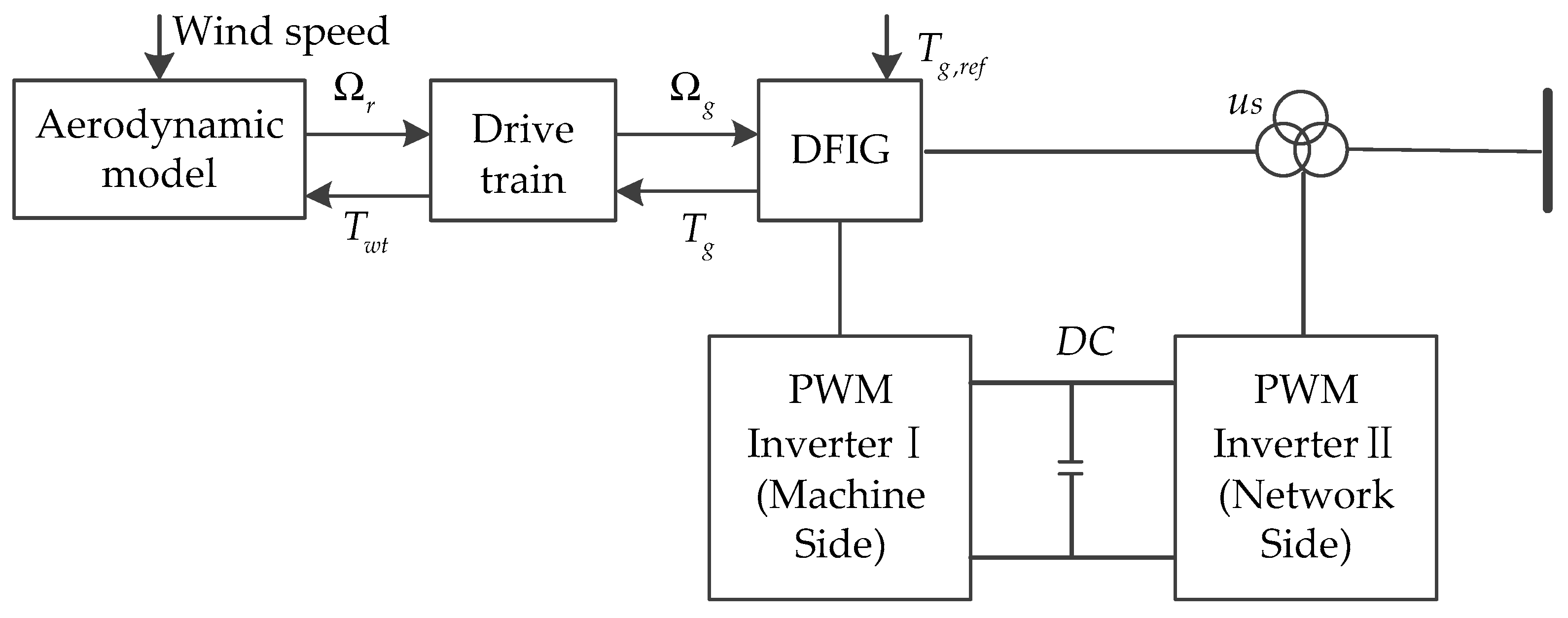
5. Mathematical Model of Wind Turbine Generation System

5.1. Dynamic Equation of Doubly-Fed Wind Turbine Generation System

According to Betz theory, the mechanical power P w t obtained by the wind turbine from the wind can be described by:
P w t = 0.5 ρ R 2 V 3 C p ( λ , β )
where ρ denotes air density, R denotes the radius of the wind wheel, V denotes the wind speed, λ denotes the tip speed ratio (TSR), β denotes the pitch angle, C p ( λ , β ) represents the conversion efficiency coefficient of wind energy, which is the function of λ and β , the TSR λ = Ω r R / V , Ω r is the mechanical angular velocity of the wind turbine.
The output torque of the wind turbine T w t can be described by:
T w t = P w t / Ω r = 0.5 ρ R 2 V 3 C p ( λ , β ) / Ω r
When the wind speed is constant, the mechanical power output of the wind turbine is only related to the wind energy conversion efficiency coefficient C p . When β remains unchanged, C p is only related to the TSR λ . For a particular wind turbine, there is and only one optimal TSR λ opt , C p max represents the maximum wind energy capture coefficient. Under the rated wind speed, fixed pitch control β = 0 is adopted. The maximum capture of wind energy can be achieved by adjusting the electromagnetic torque of the generator to follow the change of wind speed to make it reach the maximum value. when C p ( λ , β ) = C p ( λ ) , C p max 0.48 , that is the optimal tip velocity ratio.
Doubly-fed wind turbine generation systems include wind turbines, transmission systems, generators and the power grid. The turbines capture the energy of the wind and convert it into mechanical energy to turn the turbine, which in turn rotates the rotor of the doubly-fed induction motor via a driveline, thus generating electrical energy, which is transmitted to the grid through the converter. The overall structure of the doubly-fed wind turbine generation system is depicted in Figure 3.
According to the dynamic equation of the transmission system [20,21,22], the mathematical model of the wind turbine generation system can be described as:
d Ω r d t = ( D r J r + K o p t J r Ω r ) Ω r n b J r T h d Ω g d t = D g J g Ω g + 1 J g T h 1 J g T g d T h d t = 1 n b ( K l s D r D l s J r + D l s e K o p t J r Ω r ) Ω r 1 n b 2 ( K l s D g D l s J g ) Ω g D l s ( 1 J r + 1 n b 2 J g ) T h + D l s n b 2 J g T g d T g d t = 1 τ g T g + 1 τ g T g , r e f
where: K o p t = 0.5 ρ π R 5 C p max / λ o p t 2 , D r and D g denote the damping coefficients of the rotor and generator respectively, D l s denotes equivalent damping coefficient of low speed shaft; τ g denotes the time constant of the model; K l s denotes the stiffness coefficient of the equivalent low-speed shaft; J r denotes the moment of inertia of the rotor shaft of a wind turbine; T h denotes the high-speed shaft torque; J g denotes the moment of inertia of the generator rotor; T g denotes the electromagnetic torque of the generator; T g , r e f denotes the reference value of the electromagnetic torque; n b denotes the gearshift ratio; Ω g denotes the rotor speed of the generator.
By deforming Equation (27), the standard form of wind energy conversion system state equation can be obtained:
x ˙ ( t ) = A ( x ) x ( t ) + B u ( t ) y ( t ) = C ( x ) x ( t )
where x ( t ) = [ x 1 x 2 x 3 x 4 ] T =   [ Ω r Ω g T h T g ] T , u ( t ) = T g , r e f .
A ( x ) = [ ( D r J r + K o p t J r Ω r ) 0 n b J r 0 0 D g J g 1 J g 1 J g a 1 + D l s e K o p t n b J r Ω r a 2 a 3 D l s n b 2 J g 0 0 0 1 τ g ] , B = [ 0 0 0 0 0 0 0 0 0 0 0 0 0 0 0 1 τ g ] , C ( x ) = [ 1 0 0 0 0 1 0 0 0 0 0 0 0 0 0 0 ]
y ( t ) = [ y 1 y 2 ] = [ Ω r Ω g ] , a 1 = 1 n b ( K l s D r D l s J r ) , a 2 = 1 n b 2 ( K l s D g D l s J g ) , a 3 = D l s ( 1 J r + 1 n b 2 J g )

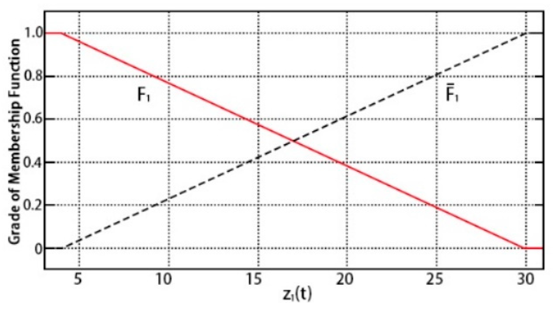
5.2. T-S Fuzzy Modeling of Doubly-Fed Wind Turbine Generation System

T-S fuzzy is carried out for the doubly-fed wind turbine generation system. By observing the system matrix A ( x ) , the fuzzy premise variables z 1 ( t ) = Ω r and z 2 ( t ) = Ω g are selected, then the membership functions of z 1 ( t ) and z 2 ( t ) are defined A ( x ) = i = 1 r u i ( z ( t ) ) A i , B ( x ) = i = 1 r u i ( z ( t ) ) B i , C ( x ) = i = 1 r u i ( z ( t ) ) C i . For simplification, the membership functions of the two fuzzy subsets can be represented by Equations (28) and (29), where z 1 ( t ) [ z 1 max   z 1 min ] and z 2 ( t ) [ z 2 max   z 2 min ] :
F 1 ( z 1 ( t ) ) = z 1 ( t ) z 1 min z 1 max z 1 min ,   F ¯ 1 ( z 1 ( t ) ) = 1 F 1 ( z 1 ( t ) ) = z 1 max z 1 ( t ) z 1 max z 1 min
F 2 ( z 2 ( t ) ) = z 2 ( t ) z 2 min z 2 max z 2 min ,   F ¯ 2 ( z 2 ( t ) ) = 1 F 2 ( z 2 ( t ) ) = z 2 max z 2 ( t ) z 2 max z 2 min
The membership functions of z 1 ( t ) is shown in Figure 4, and the membership functions of z 2 ( t ) can be implemented in the same manner.
The fuzzy rules of the T-S fuzzy model with uncertain parameters of wind turbine generation system (26) are given by:
Rule   R i : if   z 1 ( t )   is   F 1 i   and   z 2 ( t )   is   F 2 i , then:
x ˙ ( t ) = ( A i + Δ A i ) x ( t ) + ( B i ) u ( t ) y ( t ) = C i x ( t )          i = 1 , 2 , 3 , 4
After defuzzification, the equation of state of the whole fuzzy T-S system can be obtained:
x ˙ ( t ) = i = 1 4 u i ( z ( t ) ) [ ( A i + Δ A i ) x ( t ) + B i u ( t ) ] y ( t ) = i = 1 4 u i ( z ( t ) ) C i x ( t )          i = 1 , 2 , 3 , 4
where:
A i + Δ A i = [ ( D r J r + K o p t J r z 1 i ) 0 n b J r 0 0 D g J g 1 J g 1 J g a 1 + D l s e K o p t n b J r z 1 i a 2 a 3 D l s n b 2 J g 0 0 0 1 τ g ] , B i = [ 0 0 0 0 0 0 0 0 0 0 0 0 0 0 0 1 τ g ] , C i = [ 1 0 0 0 0 1 0 0 0 0 0 0 0 0 0 0 ]
Then the total state feedback controller can be produced:
u ( t ) = r ( t ) j = 1 4 u j ( g ( t ) ) K j x ^ ( t )

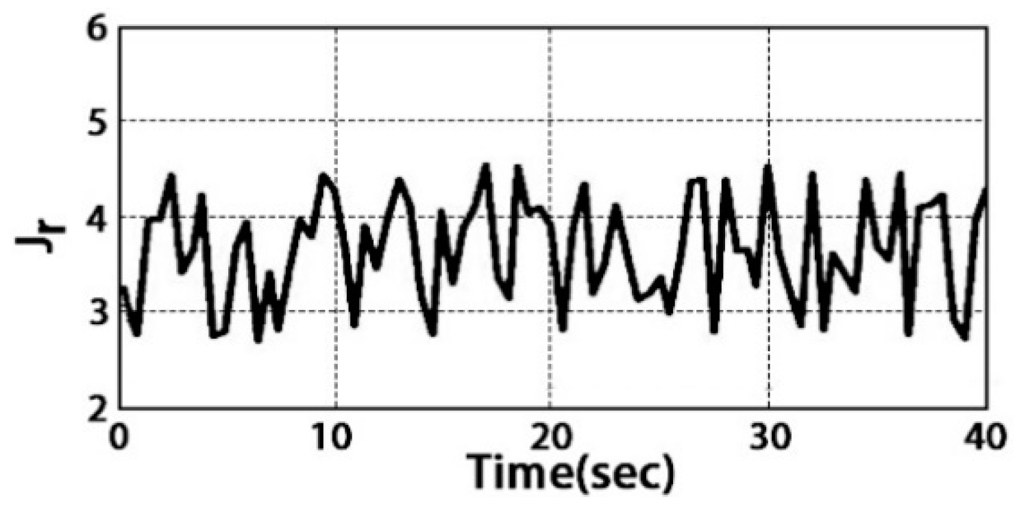
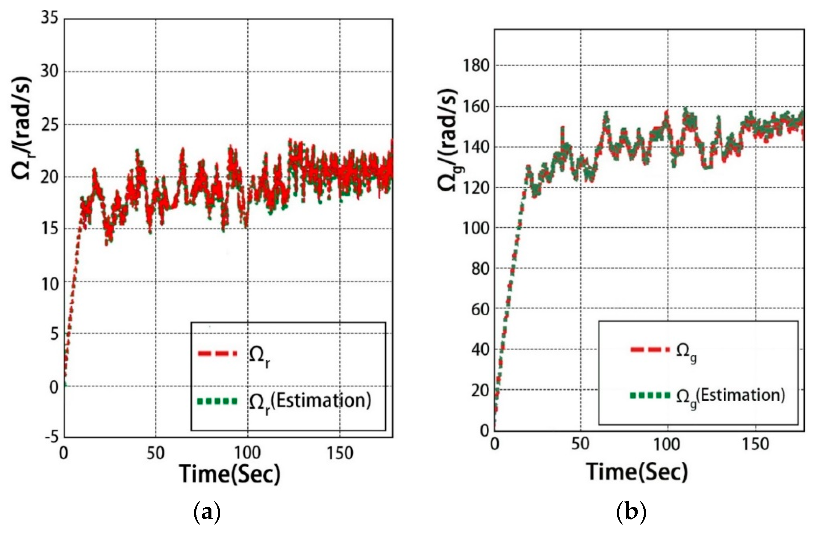
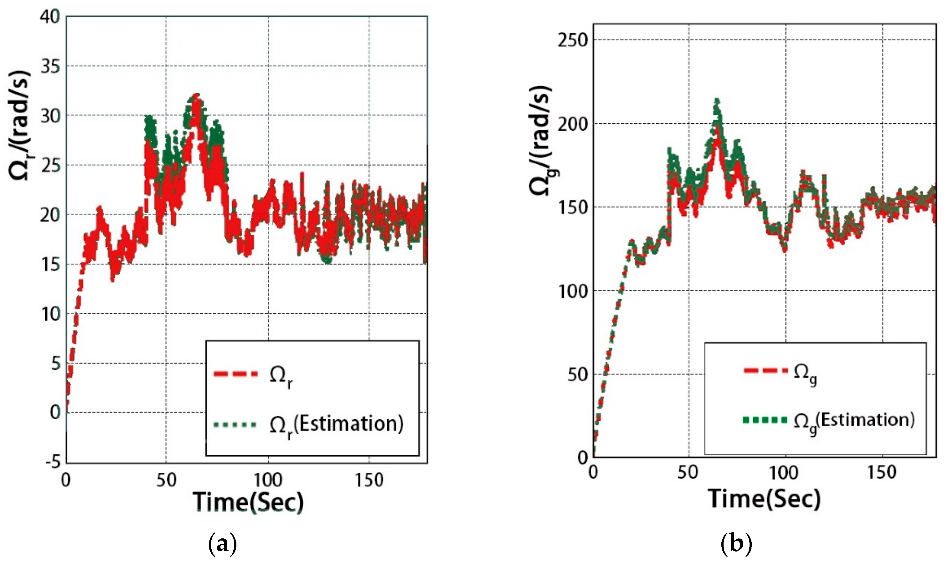
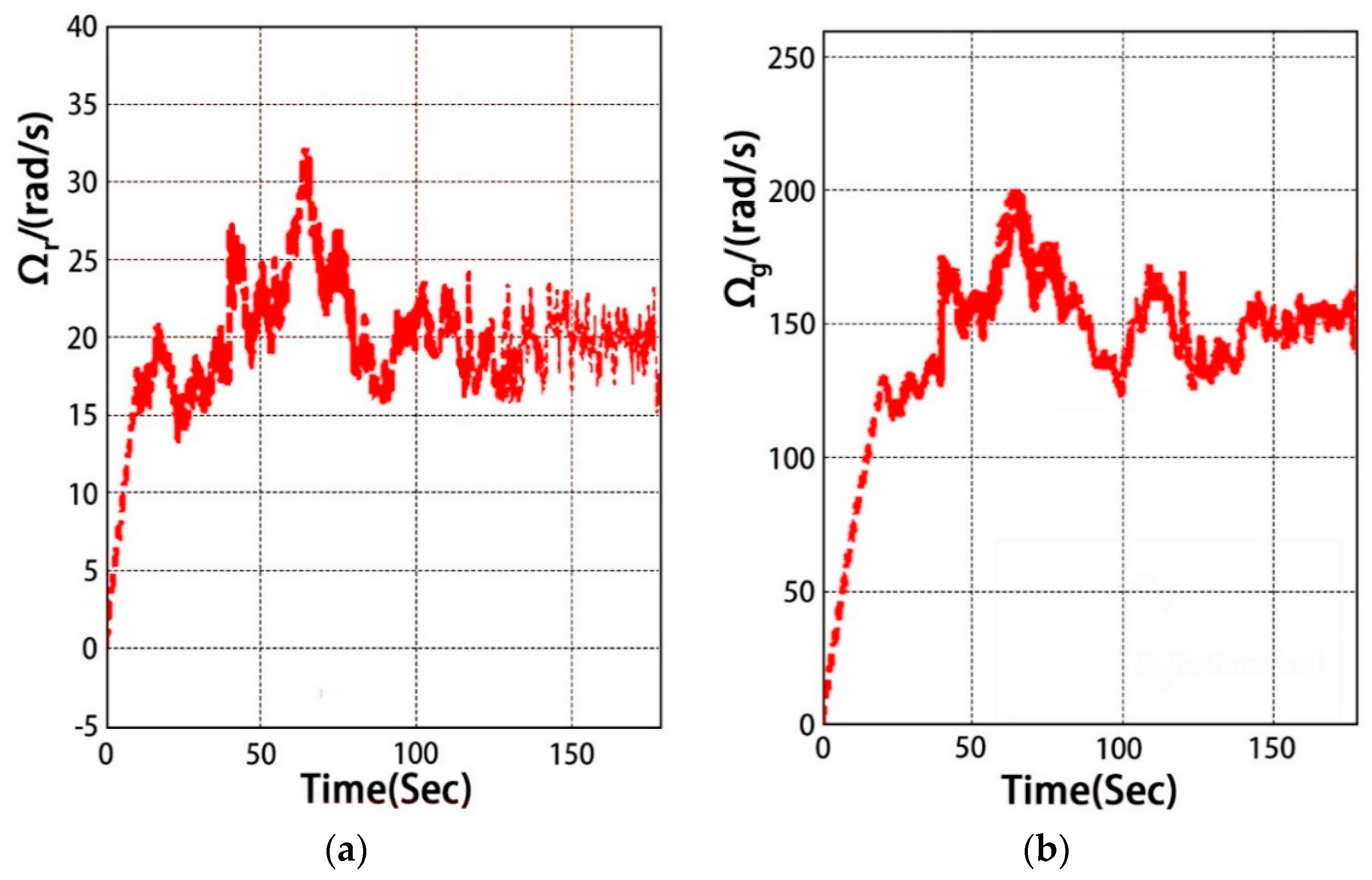
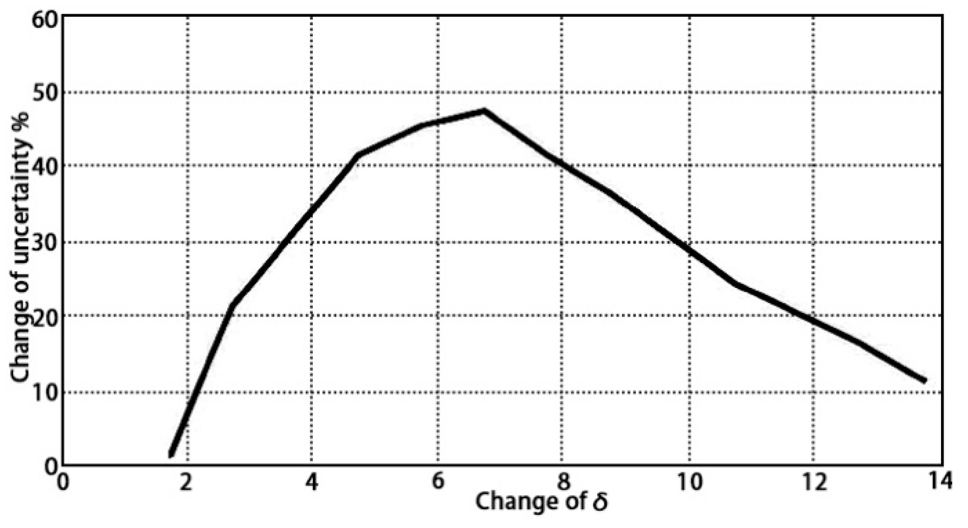
6. Simulation Results and Analysis

The simulation parameters of the doubly-fed wind turbine generation system in this paper are set as shown in Table 1.
In this paper, the sudden fault of the speed sensor of doubly-fed wind generator is described by the deviation fault. The sensor fault is taken as a function of time t , a deviation signal is applied to the output of the high-speed shaft motor speed sensor between t = 40   s and t = 80   s , as depicted in Figure 5. The sudden change of the motor speed sensor results in the change of the sensor gain, and the system output can be obtained from Equation (4):
y ( t ) = [ y 1 y 2 ] = [ Ω r . m e s ( k ) Ω g . m e s ( k ) ] = ( I + F ) [ Ω r ( k ) Ω g ( k ) ]
where Ω r . m e s ( k ) denotes the measured value of wind turbine speed and Ω g . m e s ( k ) denotes the measured value of the generator speed, F = d i a g ( f 1 , f 2 ) , f 1 , f 2 [ 0.1 , 0.1 ] defines the proportional deviation, I is the identity matrix, ( I + F ) is the sensor gain.
Considering the parameter uncertainty of the system J r + Δ J r , Let Δ J r change within 20% of the normal value. The variation of uncertainty parameter J r + Δ J r is shown in Figure 6.
Assuming that only one sensor fails at any time, the given wind speed input sequence is shown in Figure 7.
Figure 8 shows the comparison of the estimated value and the actual value of the low-speed shaft speed state Ω r and high-speed shaft speed state Ω g when the generator speed sensor fault free. In Figure 9a shows the comparison between the estimated value and the actual value of the low-speed shaft speed state when the system sensor fails, Figure 9b is the comparison diagram between the estimated value and the actual value of the high-speed shaft speed state when the system sensor fails. It is easy to see from Figure 9 between t = 40   s and t = 80   s , when the motor speed sensor of the high-speed shaft fails, both the low-speed shaft and high-speed shaft speed of the system have sudden changes and the oscillation amplitude increases. However, T-S fuzzy observer can still track the original state of the system quickly and achieve satisfactory state estimation during sensor faults.
Figure 10 shows the operation conditions of the system state when the traditional fuzzy PID controller [17] is adopted in case of sensor failure between t = 40 ~ 80   s . By comparing Figure 8 and Figure 9, It can be seen that the trajectories of Ω r and Ω g is still seriously deviated from the optimal value and it is difficult to achieve optimal compensation control.
Figure 11 gives the operation of the system’s low-speed shaft speed and high-speed shaft speed, and their enlargement between t = 50 ~ 52   s by adopting the designed robust fuzzy control strategy when sensor faults occur in the system. As can be seen from the comparison between Figure 10 and Figure 11, between t = 40 ~ 80   s the robust fuzzy controller designed during the sensor fault can significantly reduce the fluctuation range of the low-speed shaft and high-speed shaft speed, reduce the impact and vibration of the system caused by sensor fault, improve the robustness of the system, and achieve a better fault-tolerant control effect.
The study find that the proposed control strategy in the uncertain value of less than 50% has good fault tolerance effect, after that with the increase of the uncertainty parameter, the designed robust fuzzy controller is more and more difficult to compensate the effects of wind turbine generation system for sensor fault, for how to optimize the design of robust fuzzy controller to achieve better fault-tolerant control system performance will be the focus of our next research.

7. Conclusions

The problem of sensor fault tolerance control in wind turbine generation systems is studied in this paper by establishing an uncertain nonlinear system model with T-S fuzzy theory. Considering the uncertainty of nonlinear systems, the design method of a T-S fuzzy observer for fuzzy systems is presented. Meanwhile, FDI and a robust fuzzy controller are designed based on the T-S fuzzy observer. By using Lyapunov stability theory, the system stability is proved. Finally, it can be seen from the simulation results that when sensor faults occur in the wind turbine generation system, the designed fault-tolerant control method can effectively reduce the impact and oscillation caused by these faults in the system. The robustness of the system is improved to ensure the safe and stable operation of the system under fault, and the fault-tolerant control purpose of sensor fault is realized.

Author Contributions

Methodology, G.Y., T.X.; Writing original draft, T.X.; Writing—review and editing, T.X., X.H.; Performing the verification and analyzing the results, G.Y., T.X., H.S., X.H., X.W., C.F., J.L.

Funding

This paper was supported by the National Natural Science Foundation (No.60771014); Tianjin Science and Technology Support Foundation of China (No.17YFZCNC00230); Tianjin Natural Science Foundation of China (No.13JCZDJC29100).

Conflicts of Interest

The authors declare no conflict of interest.

References

  1. Liu, J.; Li, J.; Yao, X. The Economic Effects of the Development of the Renewable Energy Industry in China. Energies 2019, 12, 1808. [Google Scholar] [CrossRef]
  2. Pursiheimo, E.; Holttinen, H.; Koljonen, T. Inter-sectoral effects of high renewable energy share in global energy system. Renew. Energy 2019, 136, 1119–1129. [Google Scholar] [CrossRef]
  3. Gielen, D.; Boshell, F.; Deger, S.; Bazilian, M.D.; Wagner, N.; Gorini, R. The role of renewable energy in the global energy transformation. Energy Strategy Rev. 2019, 24, 38–50. [Google Scholar] [CrossRef]
  4. Vargas, S.A.; Esteves, G.R.T.; Maçaira, P.M.; Bastos, B.Q.; Oliveira, F.L.C.; Souza, R.C. Wind power generation: A review and a research agenda. J. Clean. Prod. 2019, 218, 850–870. [Google Scholar] [CrossRef]
  5. Lv, D.G.; D, Z.Y.; Li, S. Fault-tolerant of brushless permanent magnet motor drives with Hall sensors. Electr. Mach. Control 2019, 23, 44–52. [Google Scholar]
  6. Li, L.; He, K.; Wang, X.Y.; Liu, Y.H. Sensor fault-tolerant control for gear-shifting engaging process of automated manual transmission. Mech. Syst. Signal Proc. 2018, 99, 790–804. [Google Scholar] [CrossRef]
  7. Wang, Y.; Hua, R. A combined Time-Delay Prediction Model for Fault Diagnosis of UAV Sensors. Electron. Opt. Control 2019, 26, 86–89. [Google Scholar]
  8. Ying, L.M.; Hang, C.C.; Shu, N.Q.; Wang, D.H. Permanent magnet synchronous motor fault-diagnosis and fault-tolerant. Electr. Mach. Control 2019, 63, 1–8. [Google Scholar]
  9. Nasrolahi, S.S.; Abdollahi, F. Sensor fault detection and recovery in satellite attitude control. Acta Astronaut. 2018, 145, 275–283. [Google Scholar] [CrossRef]
  10. Xiahou, K.S.; Wu, Q.H. Fault-tolerant control of doubly-fed induction generators under voltage and current sensor faults. Int. J. Electr. Power Energy Syst. 2018, 98, 48–61. [Google Scholar] [CrossRef]
  11. Shen, Y.X.; Yang, X.F.; Zhao, Z.P. Sensor fault diagnosis for wind turbine generation system. Control Theory Appl. 2017, 34, 321–328. [Google Scholar]
  12. Zhai, D.; Lu, A.Y.; Dong, J.; Zhang, Q.L. Event triggered H−/H∞ fault detection and isolation for T-S fuzzy systems with local nonlinear models. Signal Process. 2017, 138, 244–255. [Google Scholar] [CrossRef]
  13. Kwon, O.M.; Park, M.J.; Ju, H.P.; Lee, S.M. Stability and stabilization of T-S fuzzy systems with time-varying delays via augmented Lyapunov-Krasovskii functionals. Inf. Sci. 2016, 372, 1–15. [Google Scholar] [CrossRef]
  14. Zhu, F.L.; Jiang, P.; Li, X.H. Design of Observer and Dynamic Output Feedback Fault Tolerant Controller Based on T-S Fuzzy Model. J. Xi’an Jiaotong Univ. 2016, 50, 91–96. [Google Scholar]
  15. Zhang, X.Z.; Wang, Y.N. Robust Fuzzy Control for Doubly Fed Wind Power Systems with Variable Speed Based on Variable Structure Control Technique. Math. Probl. Eng. 2014, 2014, 750101. [Google Scholar] [CrossRef]
  16. Kamal, E.; Oueidat, M.; Aitouche, A.; Ghorbani, R. Robust Scheduler Fuzzy Controller of DFIG Wind Energy Systems. IEEE Trans. Sustain. Energy 2013, 4, 706–715. [Google Scholar] [CrossRef]
  17. Chen, G.G.; Huang, S.W.; Liu, J.C.; Guo., F. Research on Fuzzy Variable Pitch Control System for Wind Turbines Based on Simulink. Res. Explor. Lab. 2016, 35, 90–94. [Google Scholar]
  18. Kamal, E.; Aitouche, A.; Ghorbani, R.; Bayart, M. Robust fuzzy fault-tolerant control of wind energy conversion systems subject to sensor faults. IEEE Trans. Sustain. Energy 2012, 3, 231–241. [Google Scholar] [CrossRef]
  19. Kamal, E.; Koutb, M.; Sobaih, A.A.; Abozalam, B. An intelligent maximum power extraction algorithm for hybrid wind-diesel-storage system. Int. J. Electr. Power Energy Syst. 2010, 32, 170–177. [Google Scholar] [CrossRef]
  20. Gálvez-Carrillo, M.; Kinnaert, M. Sensor fault detection and isolation in doubly fed induction generators accounting for parameter variations. Renew. Energy 2011, 36, 1447–1457. [Google Scholar] [CrossRef]
  21. Babypriya, B.; Anita, R. Modelling simulation and analysis of double fed induction generator for wind turbine. J. Electr. Eng. 2009, 60, 79–85. [Google Scholar]
  22. Chitti, B.B.; Mohanty, K.B. Doubly-fed induction generator for variable speed wind energy conversion systems e modeling & simulation. Int. J. Comput. Electr. Eng. 2010, 2, 141–147. [Google Scholar]
Figure 1. Overall structure of sensor fault tolerant control in wind turbine generation system.
Energies 12 03239 g001
Figure 2. The uncertainty relative to robustness index.
Energies 12 03239 g002
Figure 3. Overall structure of the doubly-fed wind turbine generation system, where u s is the grid voltage, Ω r denotes the mechanical angular velocity of the wind turbine, Ω g denotes the rotor speed of the generator, T w t denotes the output torque of the wind turbine, T g denotes the electromagnetic torque of the generator, T g , r e f represents the reference value of the electromagnetic torque.
Energies 12 03239 g003
Figure 4. The membership functions.
Energies 12 03239 g004
Figure 5. Added generator speed sensor fault signal.
Energies 12 03239 g005
Figure 6. Variation of uncertain parameters J r + Δ J r .
Energies 12 03239 g006
Figure 7. The wind speed V .
Energies 12 03239 g007
Figure 8. (a) Ω r and its estimated trajectory when the generator speed sensor fault free; (b) Ω g and its estimated trajectory when the generator speed sensor fault free.
Energies 12 03239 g008
Figure 9. (a) Ω r and its estimated trajectory when the generator speed sensor failure; (b) Ω g and its estimated trajectory when the generator speed sensor failure.
Energies 12 03239 g009
Figure 10. (a) The trajectories of Ω r with the fuzzy PID control strategy; (b) The trajectories of Ω g with the fuzzy PID control strategy.
Energies 12 03239 g010
Figure 11. (a) The trajectories of Ω r with the robust fuzzy control strategy; (b) The trajectories of Ω g with the robust fuzzy control strategy.
Energies 12 03239 g011
Table 1. Simulation Parameters.
Parameter NamesValues
Rated power P n 6   kW
Rated voltage V s 220   V
Rated speed w s 100   π rad / s
Air density ρ 1.25   kg / m 3
Blade length R 2.5   m
Transmission efficiency η 0.95
Pole pairs p 2
Rated electromagnetic torque T g 40   N m
Inertia of the generator J g 0.0092 kg m 2
Inertia of the rotor J r 3.6   kg m 2

