1. Introduction
The medium-voltage (MV) earthing switch for indoor use is normally a part of MV switchgear. All switching apparatus of the MV switchgear are subjected to type testing. The test of interest in this paper is the short-time withstand current and peak withstand current test for the MV earthing switch that is described in [
1]. The test proves the capability of the earthing switch to withstand mechanical stress due to electrodynamic forces that are caused by three-phase short-circuit currents. These forces are also called Lorentz forces. The rated short-time withstand current is chosen by the manufacturer from the R 10 series and the peak value is obtained by multiplying short-time withstand current value by 2.5 for rated frequency of 50 Hz. R10 series or Renard series is system of preferred numbers, which consists of the following numbers: 10, 12.5, 16, 20, 25, 31.5, 40, 50, 63, 80, and 100. The rated short-time withstand current is chosen by taking the number from Renard series and multiplying it with 1000. For the purpose of the analysis, the rated short-time withstand current of 16 kA/3 s and the peak withstand current value of 40 kA are chosen. There are many manufacturers of MV earthing switches that are present on the market, with each of them having their own design. One feature of the design is the cross-section profile and a number of earthing knifes per phase [
2,
3]. This paper discusses an MV earthing switch of RGB 38-25 type, manufactured by KONČAR-Electrical Equipment Inc. [
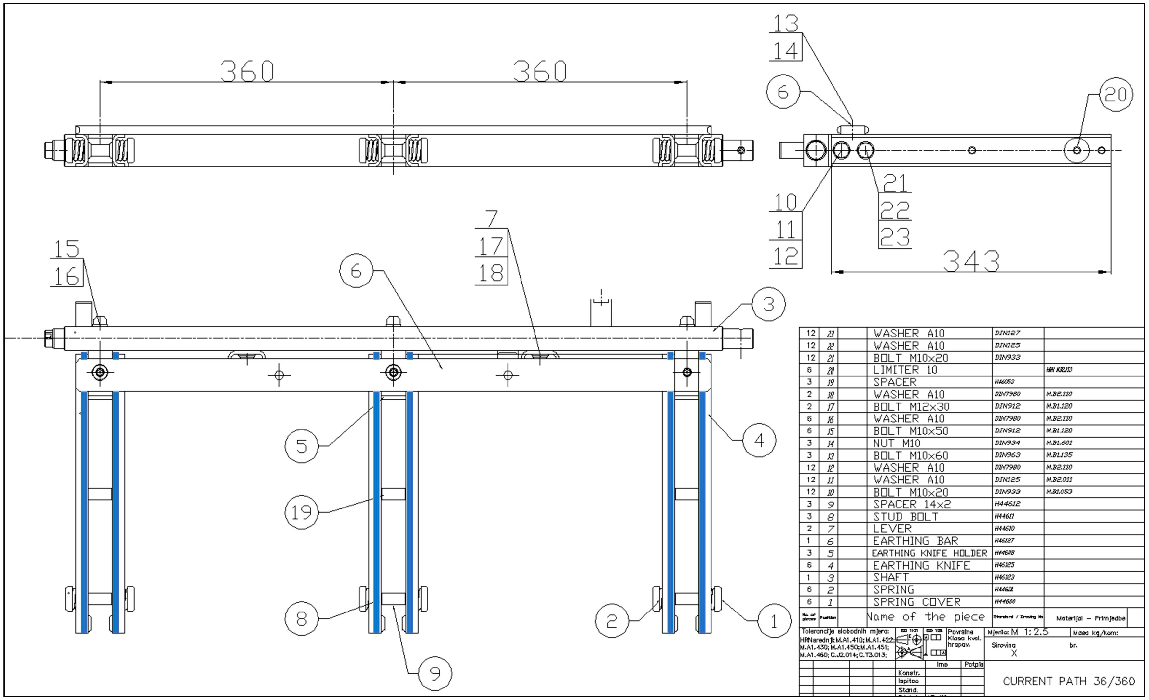
4]. In
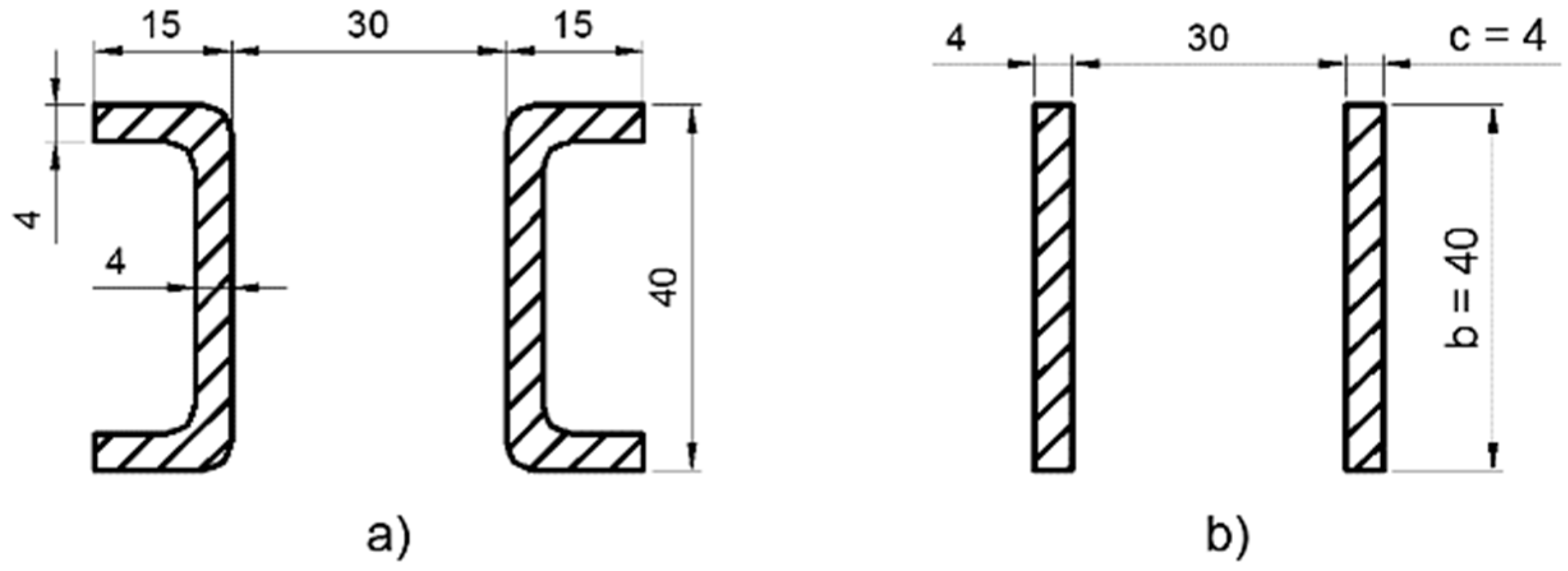
Figure 1 the current path of the earthing switch RGB 38-25 is shown. This earthing switch has two earthing knifes per phase and the cross-section of the knife is a C channel profile. The manufacturers always strive for better efficiency and performances of the product along with the cost of manufacturing reduction, material savings, and time-production saving. The C channel profile provides a bigger moment of inertia than the rectangular profile [
5]. However, the elimination of the braces, i.e., substituting a C profile with a rectangular one, leads to material and time-production savings.
The marine application is another aspect of the MV earthing switch redesign [
6]. The need for electrical power increases the use of MV switchgear equipment on board [
7]. Every MV cubical has an earthing switch. It is desirable that this system, along with other incidental systems, is smaller in size and weight. The reduction of the onboard equipment weight results in the decrease in fuel oil consumption [
8]. Furthermore, this has a positive effect on air pollution that is caused by ships. The contribution of redesign can be expressed through the Energy Efficiency Design Index (EEDI) of the ship. The EEDI is a non-prescriptive, performance-based mechanism that leaves the choice of technologies to use in a specific ship design to the industry [
9]. This paper examines the mechanical stress on earthing knifes with the rectangular cross-section during short-time withstand and peak withstand current test. The C channel profile reduces mechanical stress, but, from the cost analysis point of view, it increases the copper weight and the surface area of the earthing knife. One of the production line points of the RGB 38-25 is the silver coating of the copper earthing knifes. Silver coating is an expensive process, whose cost is proportional to the surface area of the copper. The mechanical stress on earthing knifes is calculated using the electrodynamic force calculation and mechanical static stress calculation for busbars of the rectangular cross-section [
10]. The results that were analytically obtained are compared with the results from the finite element method (FEM) calculation. FEM calculation in the time domain, along with the simplified three-dimensional (3D) model of RGB 38-25 is made in “COMSOL Multiphysics” platform (5.2, COMSOL, Inc, Stockholm, Sweden) [
11]. The simple cost analysis is conducted to highlight the influence of braces on earthing knife weight and surface. In addition to the relevant reference publications, our research also included simulation modelling that was supported by COMSOL Multiphysics software. This paper only contains the end results due to limited space. The contribution of this study lies in the proposal that the earthing switch should be minimized, i.e., further reduced in size, in order to be embedded into modern engine room switchboard.
This paper proposes the improvement of the existing earthing switch. The accent is on the theoretical aspect of improvement.
2. Simulation Currents
Even though RGB 38-25 is certified for the 40 kA peak withstand current and 16 kA short-time withstand current of 3 s duration, the norm IEC 62271-1 (IEC—International Electrotechnical Commission) prescribes tolerances for current values. The peak current (for a three-phase circuit, the highest value in one of the outer phases) shall not be less than the rated peak withstands current. It shall not exceed it by more than 5% without the consent of the manufacturer. The average of the rms values of the AC component of the test currents shall not be less than the rated value [
12]. The simulation currents that were used in this investigation comply with IEC norm prescribed tolerances. The three-phase resistive-inductive (RL) circuit is used to simulate the currents. The equations for currents in each phase are given, as follows [
13]:
where
Um is maximum phase voltage,
Z is impedance of RL circuit,
R resistance,
L inductance,
ω = 2π
f angular frequency, f frequency of the electrical grid, which is, in this discussion 50 Hz,
γ phase shift,
τ time constant of RL circuit,
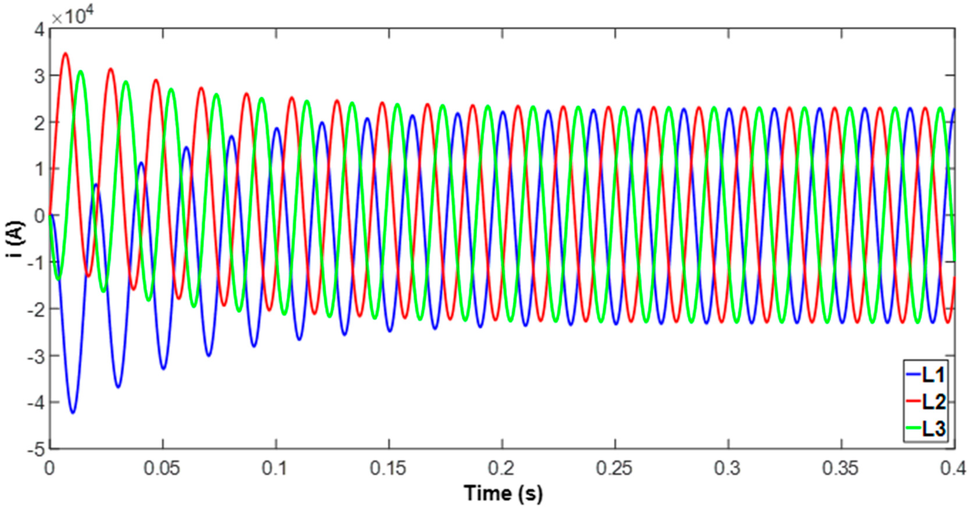
α closing angle, which defines the voltage value at the moment of short circuit occurrence. The equations are implemented in MATLAB (9.1, R2016b, The MathWorks, Inc, Natick, MA, USA). The basis for parameters of Equations (1)–(3) is the test report of the earthing switch RGB 38-25. This test report states if the earthing switch passed or did not passed the short-time withstand current and peak withstand current test. In the test report, the test currents are stated (16 kA/3 s and 40 kA peak value) and the time-current diagram of each phase is shown. To match test currents and time-current diagram curves the following parameters for Equations (1)–(3) are chosen:
Graphic representation of Equations (1)–(3), along with (4), as plotted in MATLAB, is shown in
Figure 2.
Table 1 presents peak values and short-time withstand current (r.m.s.) values.
3. Electrodynamic Forces
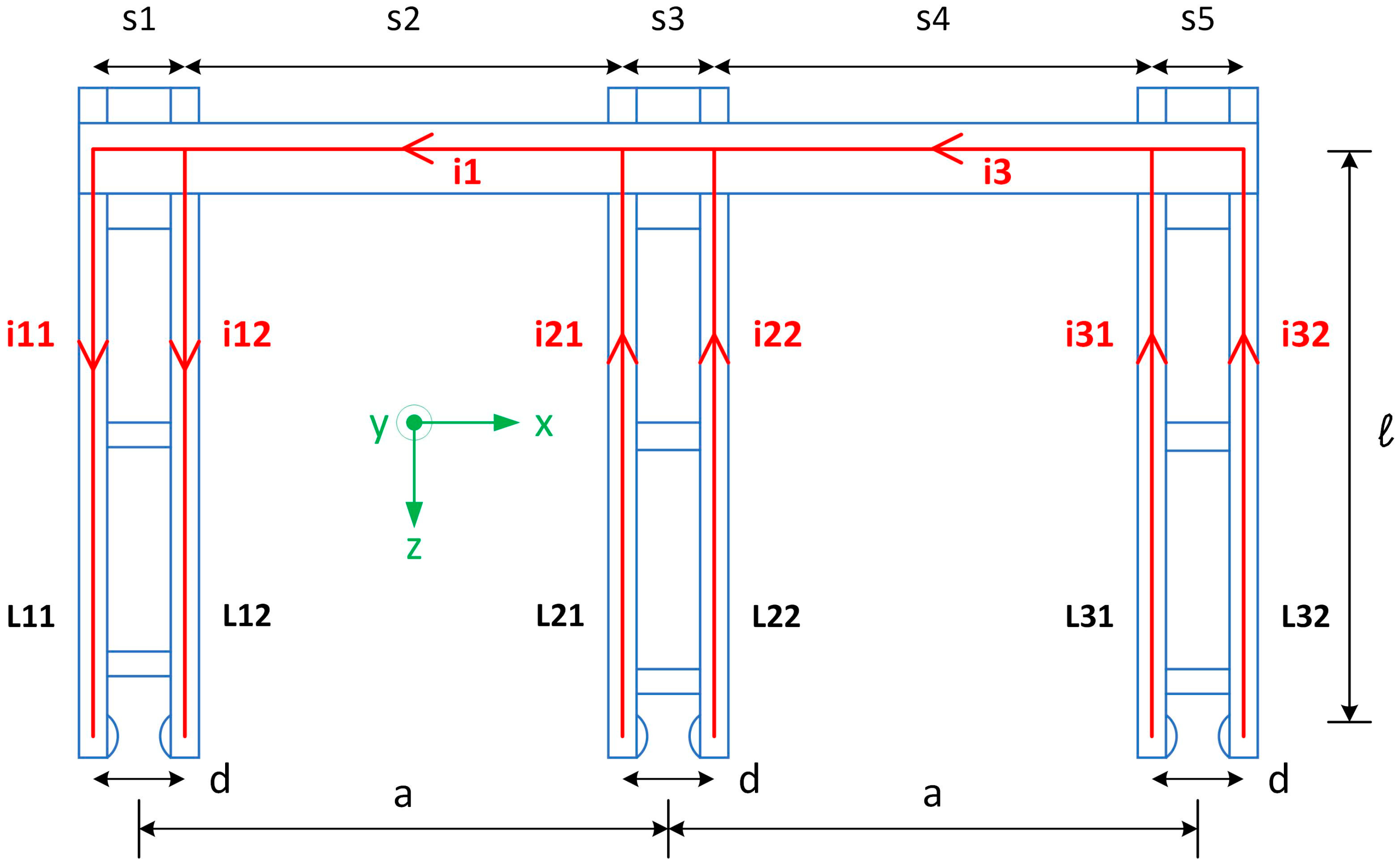
The simple approach for electrodynamics force calculation implies that all of the current paths are straight lines on which the current is concentrated. As this earthing switch has two busbars per phase, the input current is considered to be divided equally between the earthing knifes
, etc. Only the
x component of the electrodynamic force is considered.
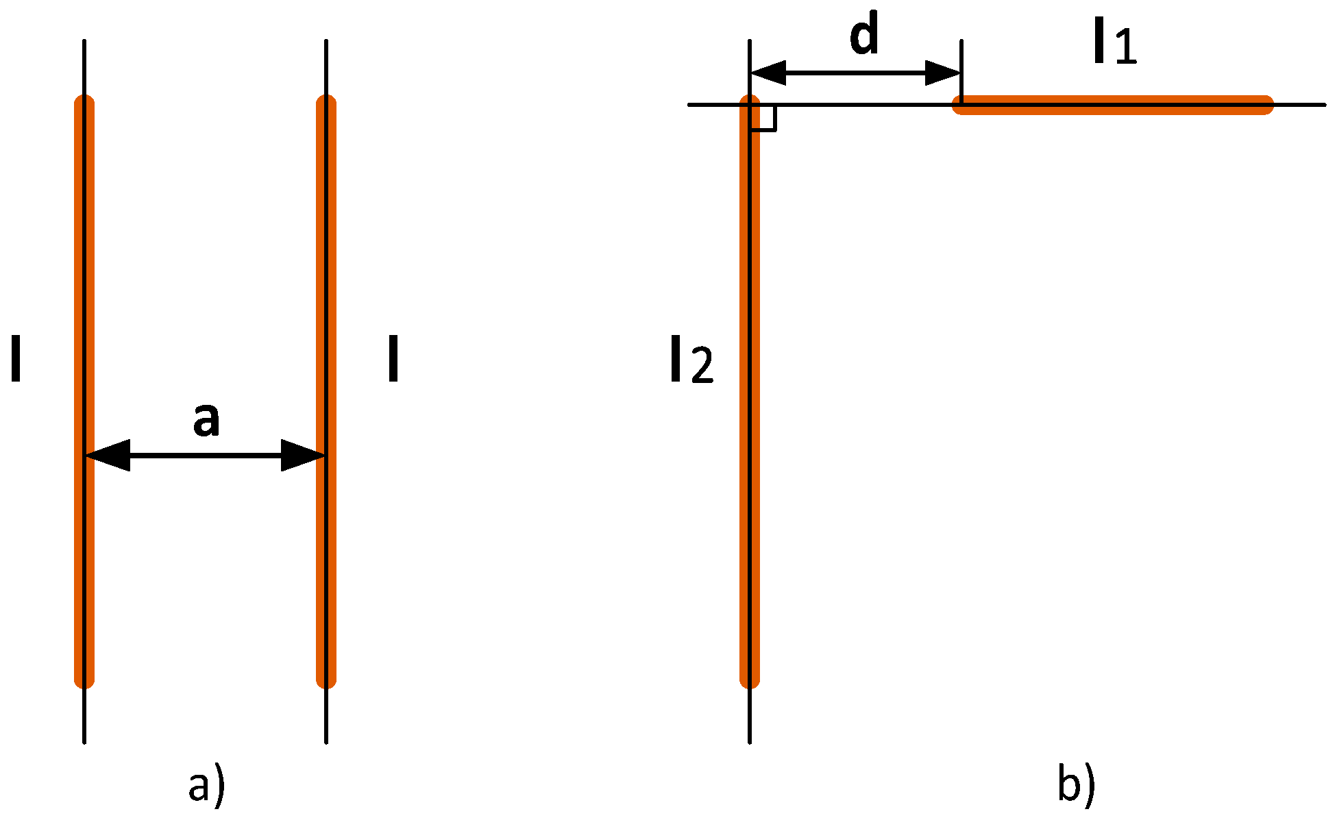
Figure 3 shows the top view of the earthing knife along with current lines, current designation for each phase, and earthing knife designations (L11–L32). Electrodynamic forces on the earthing knife are calculated by using the equations for parallel finite length conductors and equations for finite length conductors at right angle. Two conductors at right angle can be connected or separated (see
Figure 4b). Electrodynamic force on earthing knife L11 is produced by parallel conductors [
14]:
In
Table 2, the geometrical design parameters are shown.
Where
is the current through knife L11,
is the current through knife L12.
is Dwight’s coefficient [
15], which is a function of distance between two busbars of the rectangular cross-section and the dimensions of the busbar (see
Figure 5b).
is a coefficient that takes into account the finite length of busbars and it is a function of the distance between busbars and their length [
14]:
where
is the length of a busbar and
stands for the distance between conductors.
Electrodynamic force on earthing knife L11 produced by current
flowing through segment
, which is conductor at right angle and connected to L11 [
16]:
where
is the coefficient which is a function of
segment length, earthing knife L11 length
and busbars dimensions
b and
c [
16]:
where
is the coefficient for the rectangular cross-section busbar [
16].
Electrodynamic force on earthing knife L11 produced by current
flowing through segment
, which is conductor at right angle and separated by distance
:
where
is the coefficient that is a function of
segment length, earthing knife L11 length
, and separation
:
Electrodynamic forces on knife L11 that are caused by currents flowing through segments
,
, and
are analogously calculated. Total force on earthing knife L11 in
x direction [
15]:
The total forces on earthing knifes L12–L32 are calculated analogously.
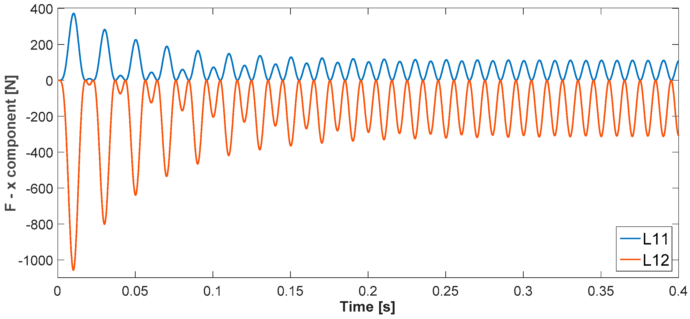
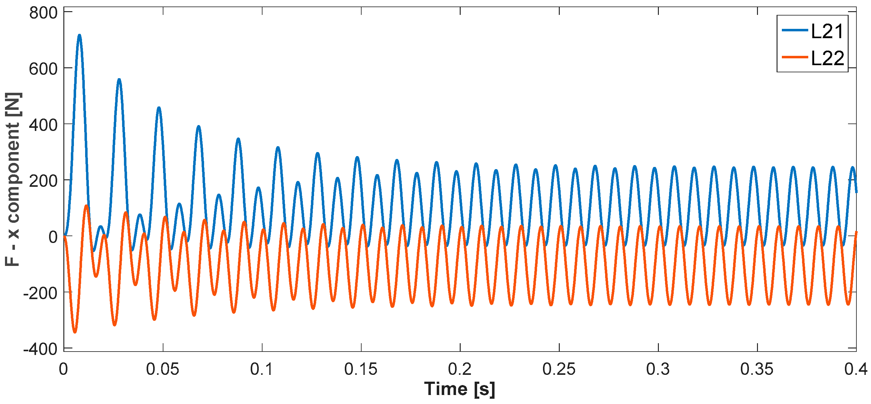
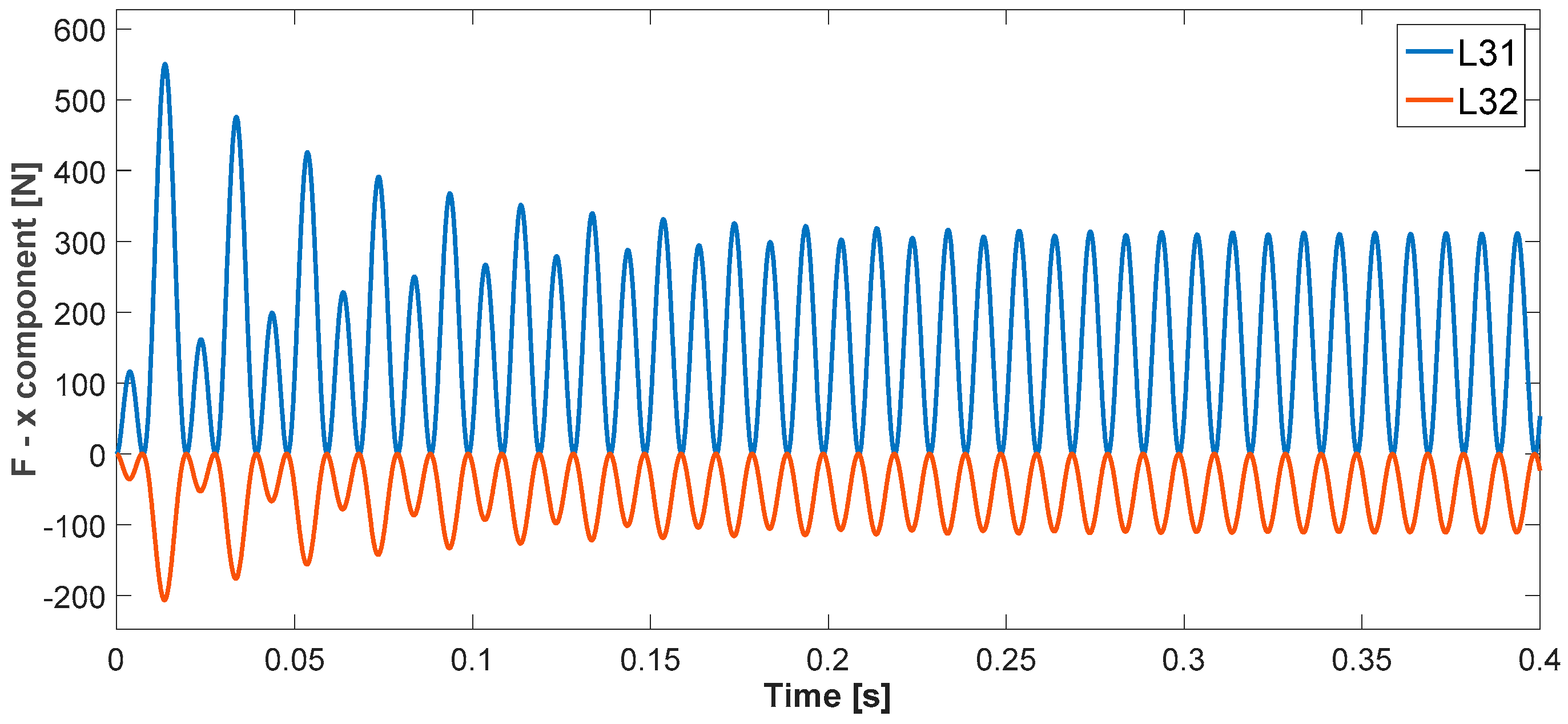
Figure 6,
Figure 7 and
Figure 8 show electrodynamic forces on earthing knifes L11–L31 in
x direction.
In
Table 3, the absolute maximum value of the force for each earthing knife in transient and in stationary state is presented. The results in
Table 3 show that knife L12 is exposed to maximum force of 1056.90 N. This force will be the input force for stress calculation.
4. Stress Calculation
In this study, the earthing knife is a beam with three spans and uniformly distributed load (see
Figure 9).
The spacers are fixed supports. The first span of length
represents the part of the beam that is fixed on both ends. The second span of length
also represents the part of the beam that is fixed on both ends. The third span of length
represents the part of the beam that is fixed at one end and is freely supported at the other end. The bending stress of the beam fixed at both ends is calculated while using equation [
17]:
where
is section modulus of the beam,
is maximum bending moment,
is the maximum force on L12 earthing knife. The bending stress of the beam fixed at one end, and freely supported at the other end, is being calculated by equation [
17]:
Table 4 presents the stress values for each span. The conductor should withstand the electrodynamics forces when:
where
is the stress corresponding to the yield point and
q is the factor that describes the increase in the permitted stress of the conductor due to its plastic behavior at places outside of its supports. The shape of the conductor should be taken into account [
18]. For the rectangular cross-section the value of
q is 1.5.
The copper that is used for earthing knifes is electrolytic tough-pitch half-hard copper, whose mechanical properties are described in [
19]. Yield stress for this copper is
(material chosen by the manufacturer). Therefore, the condition (14) is satisfied for every span in
Table 4.
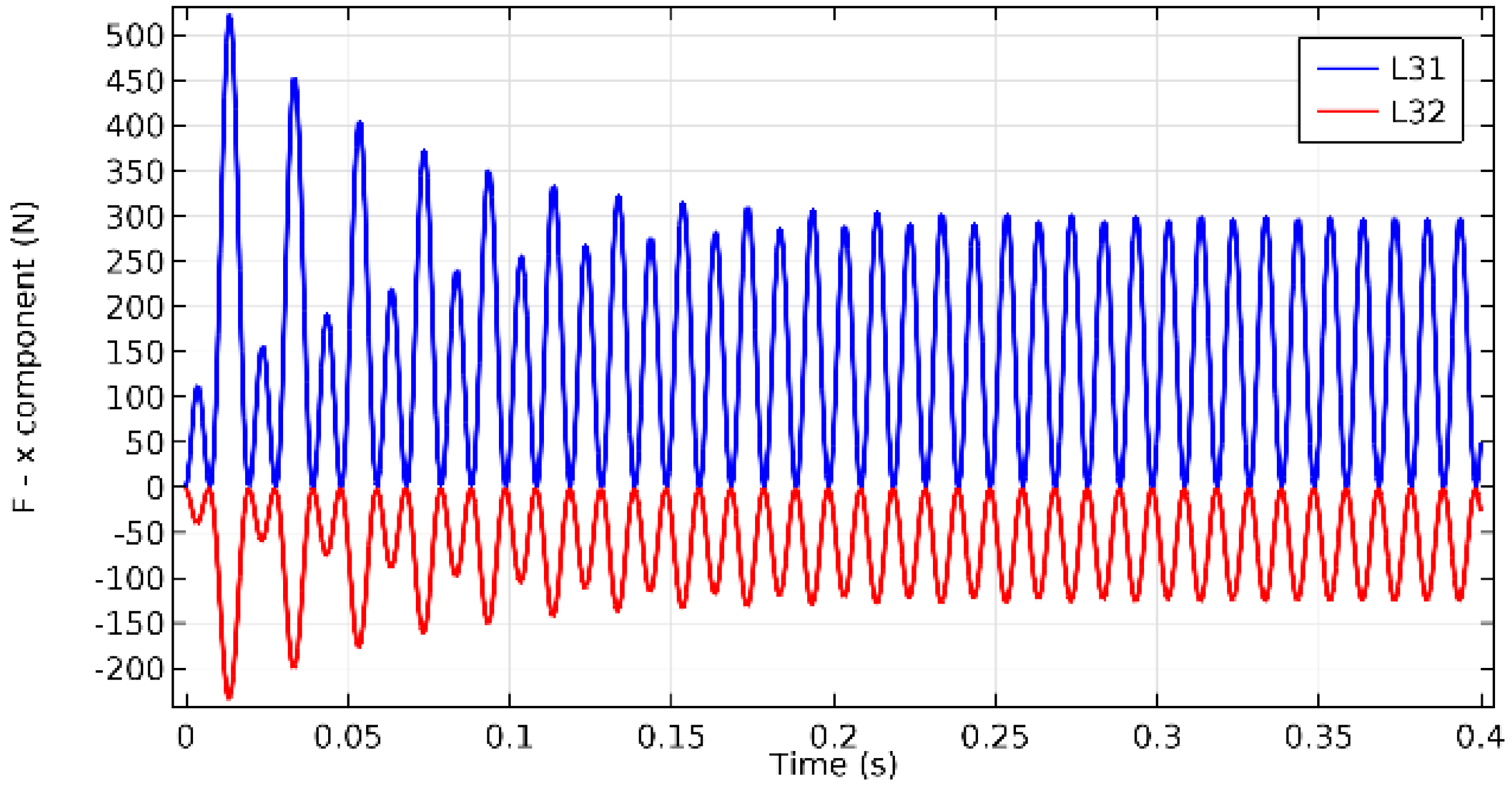
6. FEM Results
Electrodynamic force wave forms on the earthing knifes that were obtained by FEM calculation in COMSOL are shown in
Figure 11,
Figure 12 and
Figure 13.
Table 5 and
Table 6 present the comparison of the electrodynamic forces that were obtained by analytical and FEM calculations. In
Table 5, the comparison is given for the transient state. In
Table 6, the comparison is given for the stationary state. The difference between the analytical and FEM results is calculated by the following equation:
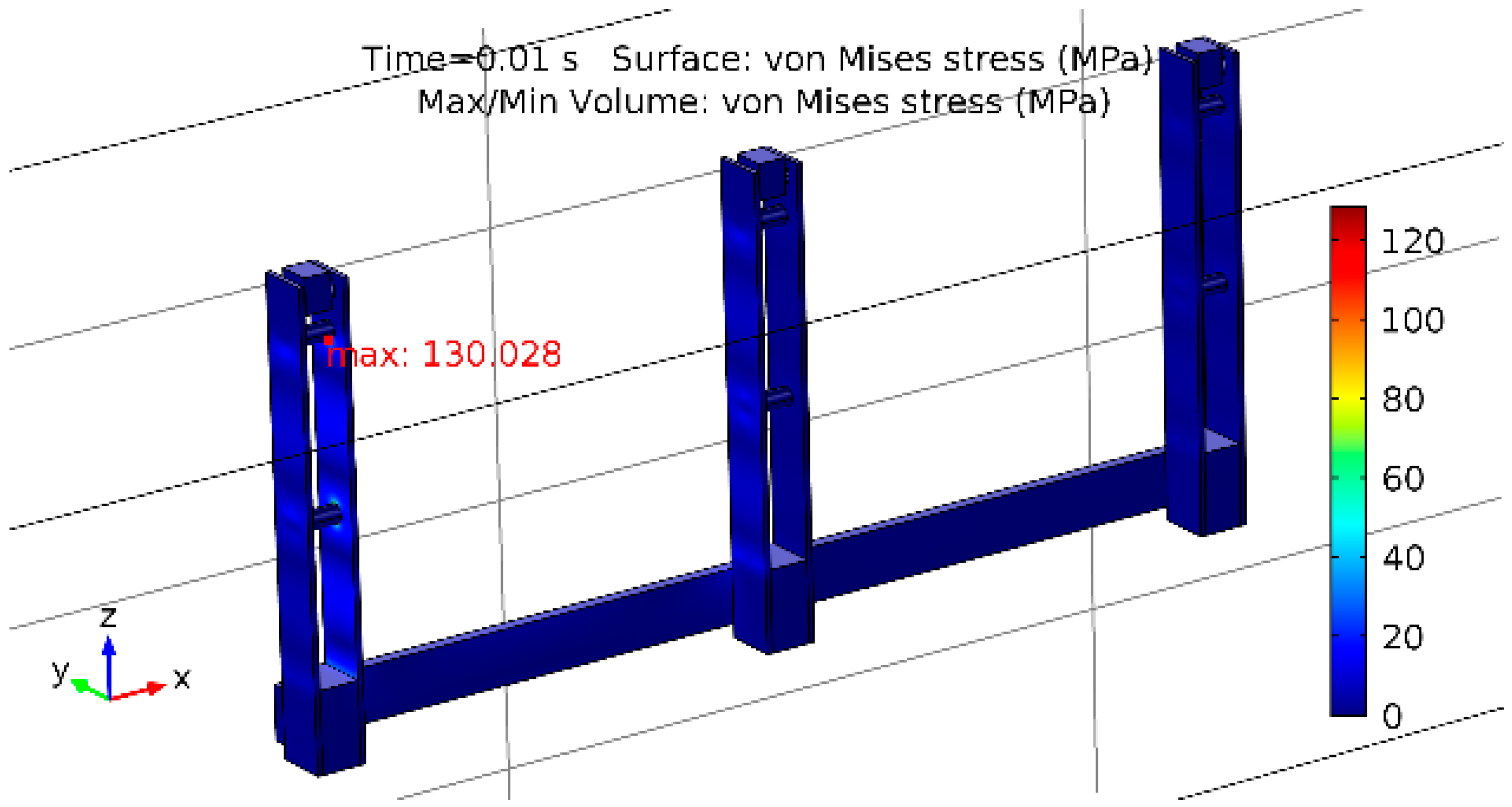
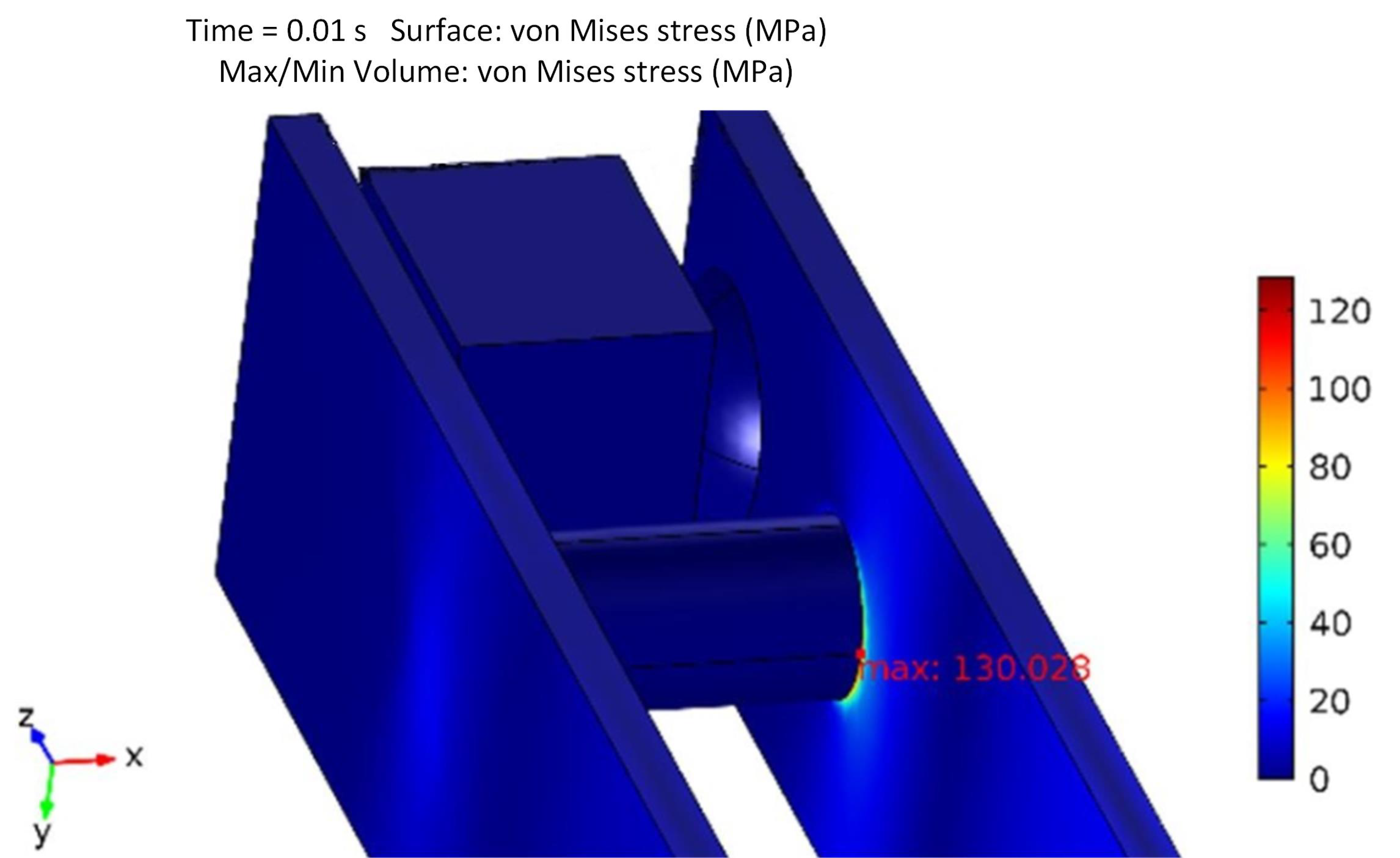
In COMOSL, the Von Mises stress is calculated [
20,
21]. The Von Mises stress distribution over the earthing switch in MPa and the point of maximum Von Mises stress (red marking) is shown in
Figure 14. The distribution is presented for
t = 0.01 s. In that moment, the maximum force occurs on knife L11.
Figure 15 highlights the point where maximum stress occurs.
Maximum Von Mises stress occurs in the point where knife L12 and upper spacer (looking from the bottom of the earthing switch) are in contact. The value of maximum stress is:
This value satisfies the Equation (14).
7. Cost Analysis
By eliminating the braces of the earthing knife, the weight and surface area of the earthing knife is reduced. Thus, the cost of material (copper) and the cost of silver coating are reduced. The mass and surface area of one earthing knife can be expressed, as follows:
where
is mass per unit length,
volume per unit length,
surface per unit length,
is mass density of material,
is the height of the rectangular cross-section,
is the width, and
is the brace length. In this research, the brace length is
(see
Figure 5a).
The calculation of the mass per unit length ratio for earthing knife with and without braces gives:
For the surface area ratio:
The mass reduction is important from the manufacturer point of view. If the function of the product is preserved less mass means lower manufacturing cost. From the application point of view the mass reduction is important in transportation industry. In this paper, the accent is on the marine industry. Mass reduction achieved by the alternative design means the mass reduction of onboard medium voltage switchboard. This further leads to lower fuel consumption that has economic and environmental impact.
8. Energy Efficiency Design Index
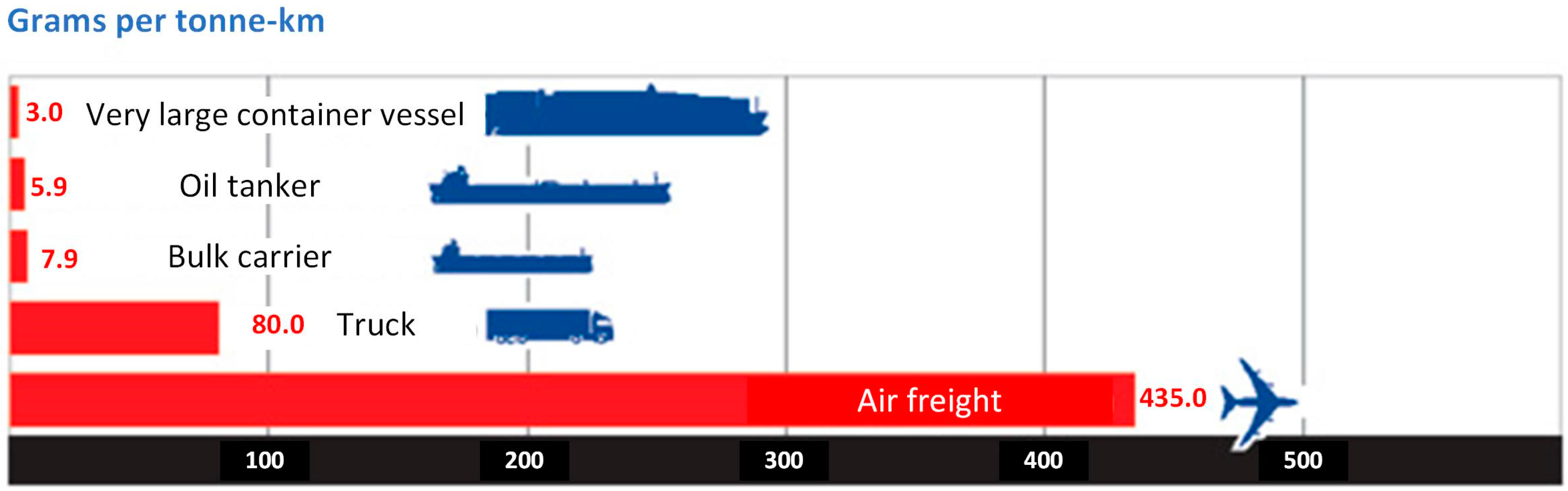
Marine traffic contributes to Greenhouse Gas (GHG) emissions. Globally, marine traffic is considered to be a highly energy efficient mode of transportation [
22].
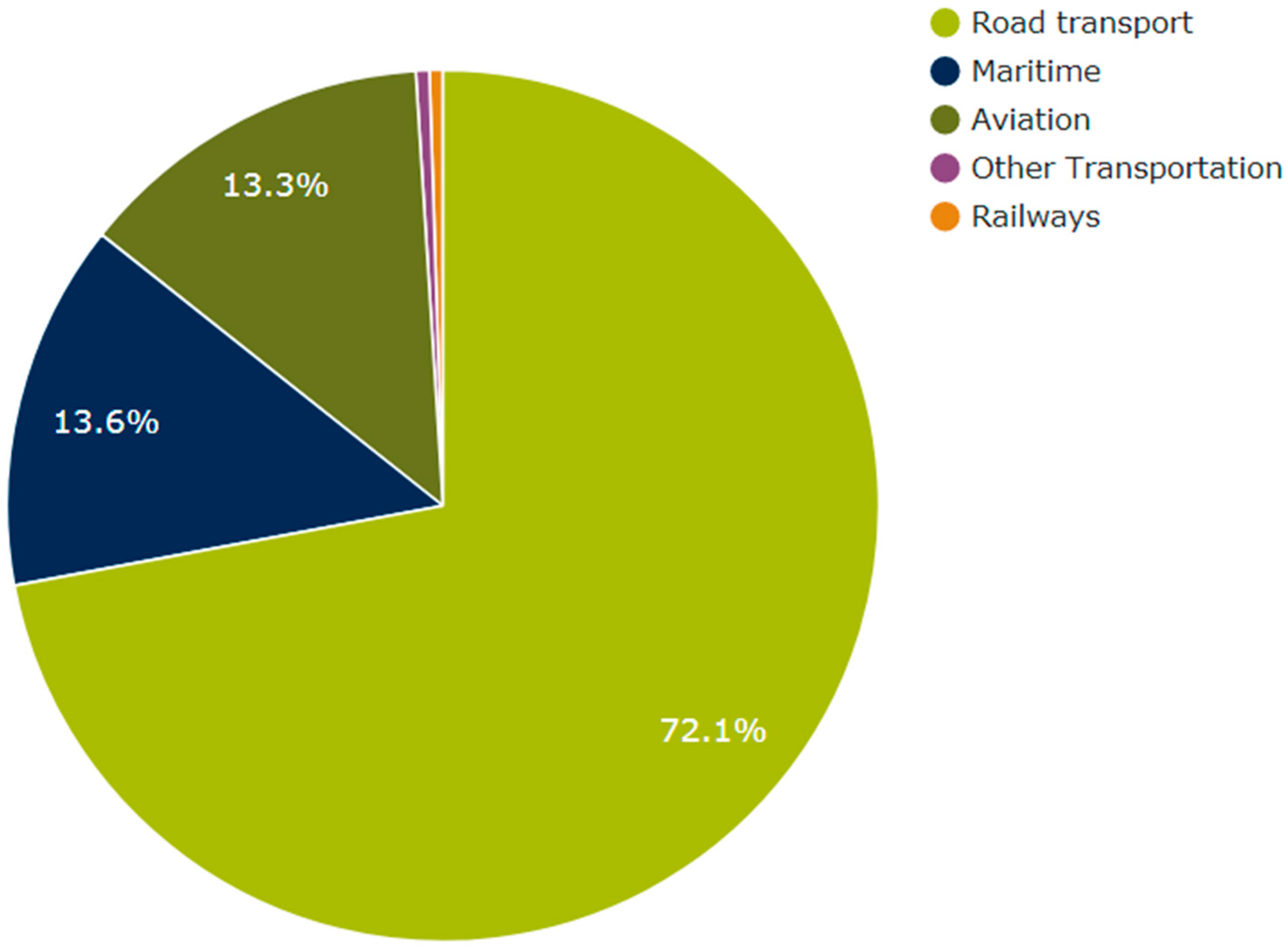
Figure 16 shows the marine traffic GHG emission on global scale. Nevertheless, this ratio can be different when one investigates GHG emission on a regional scale.
Figure 17 shows the shares of different traffic mode in GHG emissions for European Union (EU). International Maritime Organization (IMO) formulated the Energy Efficiency Design Index (EEDI) with a purpose to reduce CO
2 emission from shipping. Since 1st January 2013, every ship must have the International Energy Efficiency Certificate (IEEC). One of the conditions, which is relevant to this study, is compliance with EEDI requirements. EEDI is a technical measure that promotes the use of energy efficient equipment on ships [
25]. Factors that define EEDI are ship power system CO
2 emission, deadweight tonnage (DWT), and speed
V (in knots). Simplified formula for EEDI taken from [
26,
27] is:
where ME is short for Main Engines, AE is short for Auxiliary Engines, Transport work is the product of DWT and the speed of the ship. Complete formula can be found in [
28,
29]. The MV earthing switch is one of the many components on the ship that optimization can contribute to overall EEDI reduction. The contribution comes from the Efficiency technologies (ET) term in the Equation (21):
where
is availability factor of individual efficiency technologies,
is main engine power reduction due to individual technologies for mechanical energy efficiency,
is main engine composite fuel factor, and
is main engine specific fuel consumption.
The mass reduction of the earthing switch, thus also the mass reduction of medium voltage electrical equipment on bord is:
where
is the volume of the one knife with braces,
is height of the knife,
is the width of the knife,
is the brace length,
is the length of the knife,
is the mass of one knife with braces,
is the mass of the six knifes with braces,
is the volume of the one knife without braces,
is the mass of one knife without braces,
is the mass of the six knifes without braces,
is copper density, and
is mass reduction due to earthing knifef braces elimination.
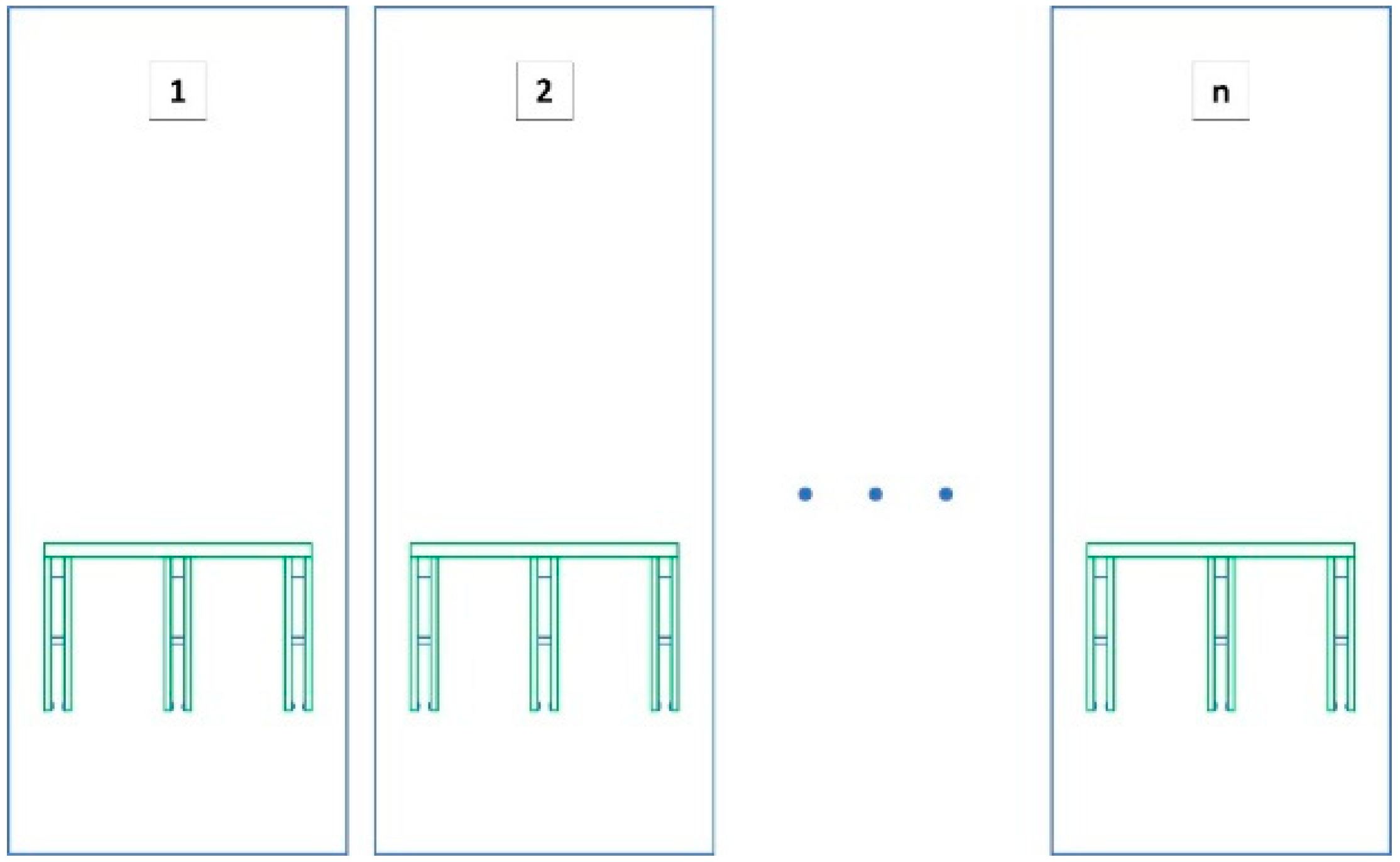
The ship power substation can have anywhere between 3 to 40 medium voltage switchgear feeders. This depends on the installed power of the ship. Every feeder contains a earthing switch (
Figure 18). This gives the mass reduction of a onboard substation:
where
is mass reduction of the substation due to the mass reduction of the earthing switch and
is the number of feeders of the substation. For
, the mass reduction is
and for
,
.
Even though the overall mass reduction of one earthing switch is negligible when compared to merchant ship or a cruise ship, the idea is to encourage the manufacturers of electrical equipment to reduce the mass and the dimensions of electrical power system components. In this way, the electrical part of the ship can contribute to the energy efficiency of the ship.
Mass reduction of onboard electrical equipment results in total ship resistance decrease, which leads to lower power demand from the main engine to maintain constant speed, thus the overall effect is lower fuel consumption.
9. Conclusions
The investigation is made with the aid of a simplified model while using an analytical approach for electrodynamic force and the static stress calculation along with FEM approach in the “COMSOL Multiphysics” platform. The results regarding electrodynamic forces in transient and stationary states are in good compliance with all knifes, except for L11 and L32. These knifes are the outermost knifes.
Even though the nature of the calculated stresses is different, the analytical approach gives static stress and an FEM analysis gives the information about Von Mises stress. The overall results show that maximum stresses are below the yield point of the used material. Therefore, the produced results indicate that the earthing switch without braces can withstand electro dynamical forces that are produced by simulation currents during the type test. In addition, it is shown that brace elimination provides significant cost saving in material and silver coating.
The Energy Efficiency Design Index is introduced as a measure of overall ship efficiency regarding CO2 production. It is qualitatively shown how mass reduction of the earthing switch can affect the EEDI.
The future research will incorporate the geometry design investigations regarding mass and size reduction, thus contributing to CO2 reduction from ships due to electrical equipment component. The next step is to investigate the electrodynamic forces for the reduced distance between earthing knifes of the same size. By reducing the distance between them, the mechanical element, which holds the earthing knifes, will also be reduced in size and mass.


