Article

Current-Limiting Soft Starting Method for a High-Voltage and High-Power Motor

1
School of Automation, Wuhan University of Technology, Wuhan 430070, China
2
Department of Civil and Environmental Engineering, University of Wisconsin-Madison, Madison, WI 53706, USA
*
Author to whom correspondence should be addressed.
Energies 2019, 12(16), 3068; https://doi.org/10.3390/en12163068
Submission received: 17 July 2019 / Revised: 8 August 2019 / Accepted: 8 August 2019 / Published: 9 August 2019

Abstract

:
Focusing on the starting problems of a high-voltage and high-power motor, such as large starting current, low power factor, waste of resources, and lack of harmonic control, this paper proposes a current-limiting soft starting method for a high-voltage and high-power motor. The method integrates functions like autotransformer voltage reduction–current limiting starting, magnetron voltage regulation–current limiting starting, and reactive power compensation during starting, and then the power filtering subsystem is turned on to filter out harmonics in power system as the starting process terminates. According to the current-limiting starting characteristic curve, the topological structure of the integrated device is established and then the functional logic switching strategy is put forward. Afterwards, the mechanisms of current-limiting starting, reactive compensation and dynamic harmonic filtering are analyzed, and the simulation and experimental evaluation are completed. In particular, the direct starting and the current-limiting are performed by developing a simulation system. In addition, a 10 kV/19,000 kW fan-loaded motor of a steel plant is chosen as the subject to verify the performance of the current-limiting soft starting method. As shown by the experimental results, the motor’s starting current is about 2 times that of its rated current, the power factor is raised to over 0.9 after the reactive power compensation, and the harmonic filter can effectively eliminate current harmonics and reduce the total harmonic distortion (THD) of supply currents.

Graphical Abstract

1. Introduction

The high-voltage and high-power motor with its voltage over 6 kV and power over 10 thousand kilowatts has been used in a wide variety of fields. The major starting methods for a high-voltage and high-power motor are voltage reduction starting, voltage regulation soft starting, and variable frequency soft starting, which can be further divided into discrete variable frequency starting and continuous variable frequency starting. The high-voltage converter-based soft starting method performs better, yet its use is limited by its complicated technology, high price and heavy dependence on importing. The voltage reduction starting method consists of motor stator winding series reactor starting, autotransformer starting, and star-triangle switching starting. The voltage regulation soft starting method can be classified into motor stator winding series liquid resistance soft starting [1,2,3], thyristor voltage regulation soft starting [4,5,6], and magnetic saturation reactor voltage-reduction soft starting [7,8,9]. The above mentioned soft starting approaches can solve most starting problems faced by high-voltage and low-power motors, yet they fail to do the same for high-voltage and high-power motors. Therefore, the current-limiting of the high-voltage and high-power motor under no-load, light load, and heavy load multitasking conditions and the reactive power compensation of the motor while it starts remain to be explored [10,11,12,13].
To realize the soft starting of a high-voltage and high-power motor, the following problems should be addressed [14,15,16]:
(1) The starting current of the high-voltage and high-power motor during soft starting should be restricted to avoid large impact on the power grid and damage to the motor and its driving equipment.
(2) The power factor of the high-voltage and high-power motor during soft starting should be increased to save energy and ensure the voltage stability of power grid.
At present, researchers have carried out lots of detailed studies on the motor voltage-regulating device. In Reference [17], as liquid resistance dropped gradually from the maximum value to zero, the motor could accelerate at a constant speed until it reached the nominal speed, thereby realizing soft starting. A middle-high power motor controller was proposed in [18], which used Programmable Logic Controller (PLC) as a magnetic control soft starter. A novel induction motor soft starter based on a magnetically controlled reactor was introduced in Reference [19]. In Reference [20], the researcher analyzed the torque oscillation of discrete variable frequency soft starting method during the starting process. Finally, in Reference [21], the performance of an on-off convertor-based soft starter of a middle-high voltage and high-power motor was investigated. According to the review, the existing high-voltage motor starters are suitable for low-power motors, but they are unable to meet the requirements on current-limiting and reactive power compensation during the starting process of high-voltage and high-power motors. The magnetic control soft starting method [22,23,24,25,26,27] controls high voltage with low voltage, so the starters are not restricted by the voltage withstand ability of thyristor and the magnitude of current, thereby widening the application range of soft starters. This soft starting method is able to solve the starting problems faced by the high-voltage and high-power motor. However, the high-cost magnetron voltage regulation part was removed after the starting process, resulting in a waste of resources.
This paper, aiming at such starting problems of a high-voltage and high-power motor as large starting current, low power factor, a waste of resources, and a lack of harmonic control, develops a current-limiting soft starting method for a high-voltage and high-power motor. First, the principle of the proposed current-limiting soft starting method is discussed. The current-limiting starting characteristic curve of a high-voltage and high-power motor is obtained, the topological structure of integrated device is established, and a functional logic switching strategy is put forward. Second, the mechanisms of current-limiting starting, reactive compensation and dynamic harmonic filtering are analyzed. The direct starting and the current-limiting starting based on autotransformer voltage reduction–current limiting starting (AVRCLS), magnetron voltage regulation–current limiting starting (MVRCLS), and reactive power compensation (RPC) are performed by developing a simulation system. With a 10 kV/19,000 kW fan-loaded motor of a steel plant as the subject of study, a current-limiting soft starter with RPC used for the high-voltage and high-power motor based on the theoretical findings is designed, and the fan-loaded starting experiment is conducted with the soft starter. The experimental results demonstrate that the motor’s starting current decreases from 6.5 to 2 times as large as its rated current, that the power factor is raised to over 0.9 after RPC, and that the harmonic filter effectively eliminates current harmonics and reduces the total harmonic distortion (THD) of supply currents.
The rest of the paper is organized as follows. Section 2 illuminates the principle of the proposed current-limiting soft starting method. Section 3 details and analyzes the proposed current-limiting soft starting method. Section 4 reports the experimental results. Section 5 concludes the paper and points out future work to be done.

2. Method Principle

Aiming at cracking problems like large starting current, low power factor, a waste of resources, and a lack of harmonic control in a conventional soft starter for a high-voltage and high-power motor, a current-limiting soft starting method for a high-voltage and high-power motor was proposed. The method integrated functions like AVRCLS, MVRCLS, and RPC during starting. When the starting process terminated, a power filtering subsystem was turned on to filter out harmonics in the power system. This section mainly includes current-limiting starting characteristic curve, topological structure, and function logical switching strategy.

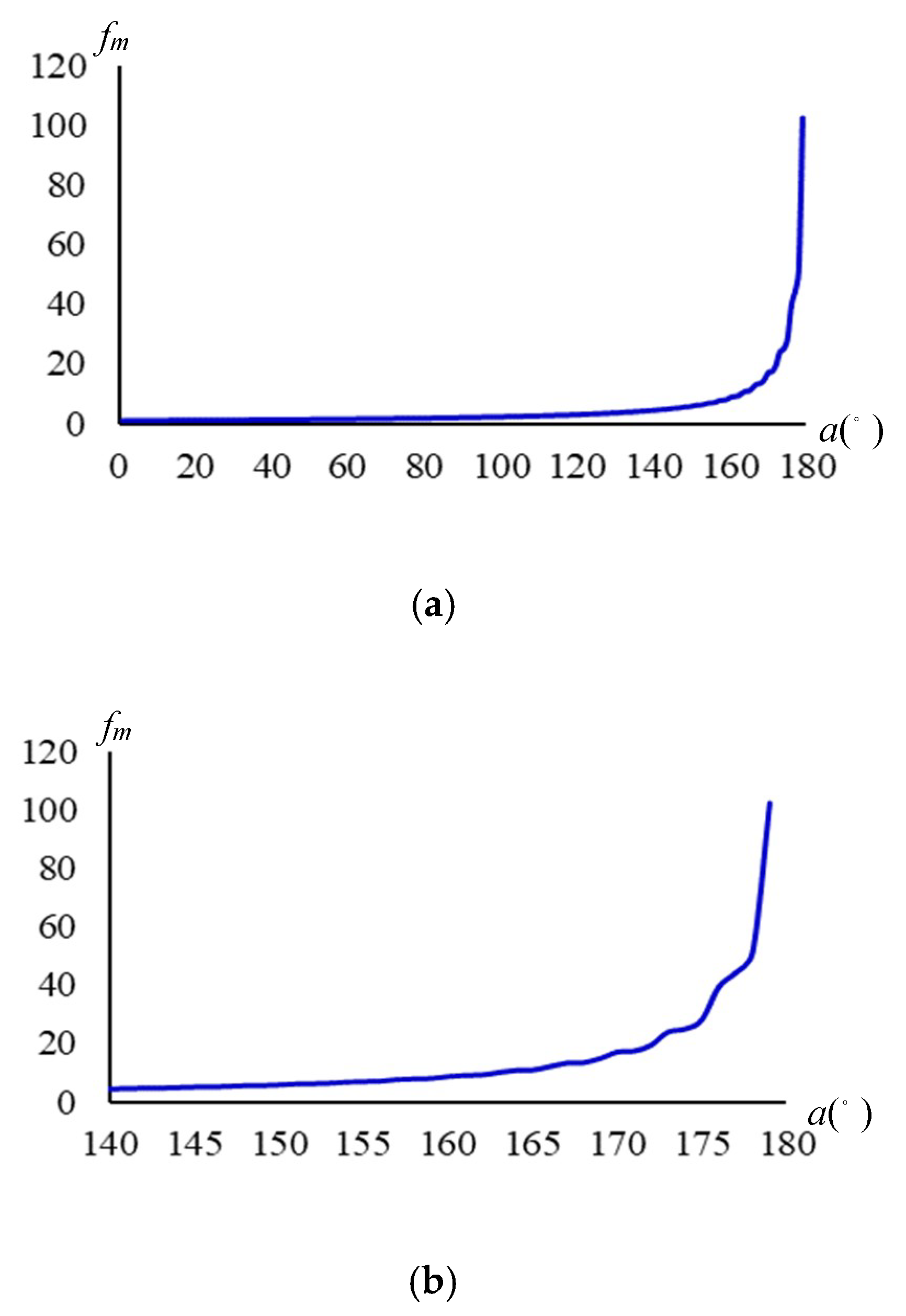
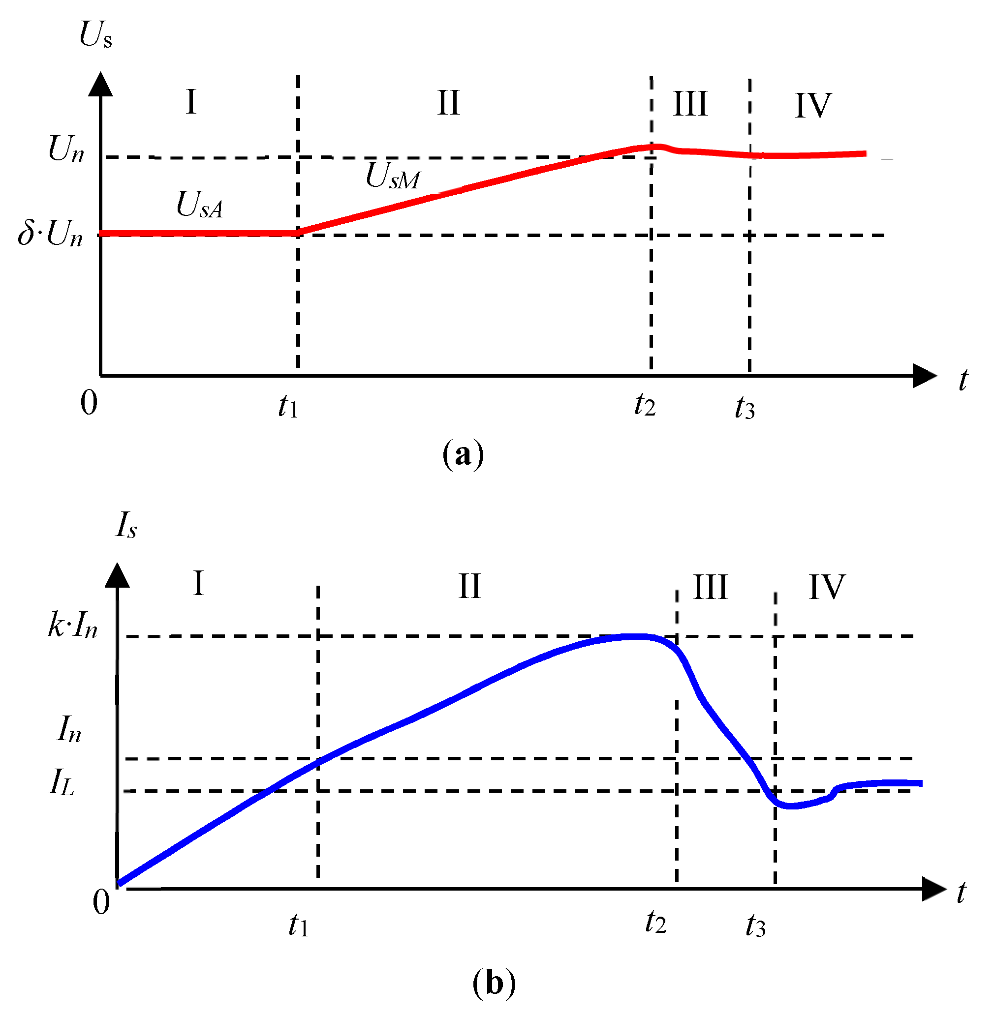
2.1. Current-Limiting Starting Characteristic Curve

As shown in Figure 1, the high-voltage and high-power motor was expected to run by following the characteristic curve in stage I to III and to meet the requirements of a high-voltage and high-power motor on starting.
In Figure 1, Un, In, IL, Us and Is stand for the nominal voltage, rated current, load current, starting voltage, and starting current of the high-voltage and high-power motor, respectively. I, II, III, and IV denote the four stages for AVRCLS with RPC, MVRCLS with RPC, termination of starting, and power filtering. t1, t2, and t3 represent the switching time of the MVRCLS subsystem, full voltage run, and power filtering subsystem respectively. UsA and UsM are output voltages of the AVRCLS subsystem and MVRCLS subsystem, respectively. The starting current times k was the control object, generally in the range of 2–4.
Equation (1) could be satisfied by regulating the starting voltage Us during starting.
U s = { δ U n   0 t < t 1 δ U n + U s M ( t ) t 1 t < t 2 U n t = t 2
where, δ is the coefficient of auto-voltage that could be adjusted according to the practical situation. It was about 0.4–0.7. The voltage characteristics of the motor shown in Figure 1a could be realized by finding the optimal δ, t1, t2 and U s M ( t ) .
(1) AVRCLS with RPC (STAGE I, 0~t1)
First, the RPC subsystem was turned on, and then the AVRCLS subsystem was turned on. The partial voltage of the motor obtained from the AVRCLS subsystem was δ·Un. The starting current Is of the high-voltage and high-power motor was smaller than rated current In.
(2) MVRCLS with RPC (STAGE II: t1~t2)
When the starting current Is of the motor approached the rated current In, the MVRCLS subsystem was switched on. In this stage, the magnetic control voltage regulation could be realized, so the voltage of the motor increased from δ·Un to Un progressively. The RPC subsystem provided the reactive power required in the starting process of the motor, thus increasing the power factor.
The current-limiting of the high-voltage and high-power motor was realized in stages I and II.
(3) End of starting process (STAGE III: t2~t3)
The soft starting process of the motor terminated when the starting voltage Us reached Un and the current Is was equal to the load current IL. Afterwards, the motor worked normally under full voltage.
(4) Power filtering subsystem (STAGE IV: AFTER t3~)
With the motor working normally under full voltage, the power filtering subsystem was switched to filter out harmonics in power system.

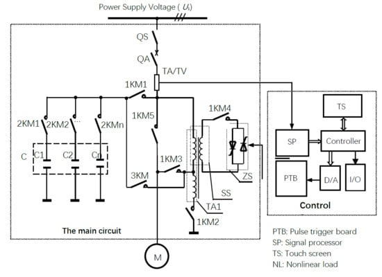
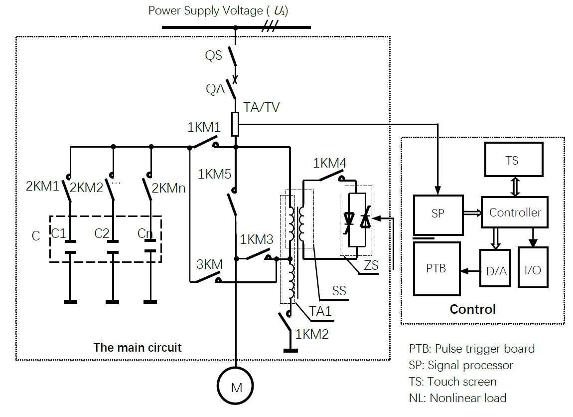
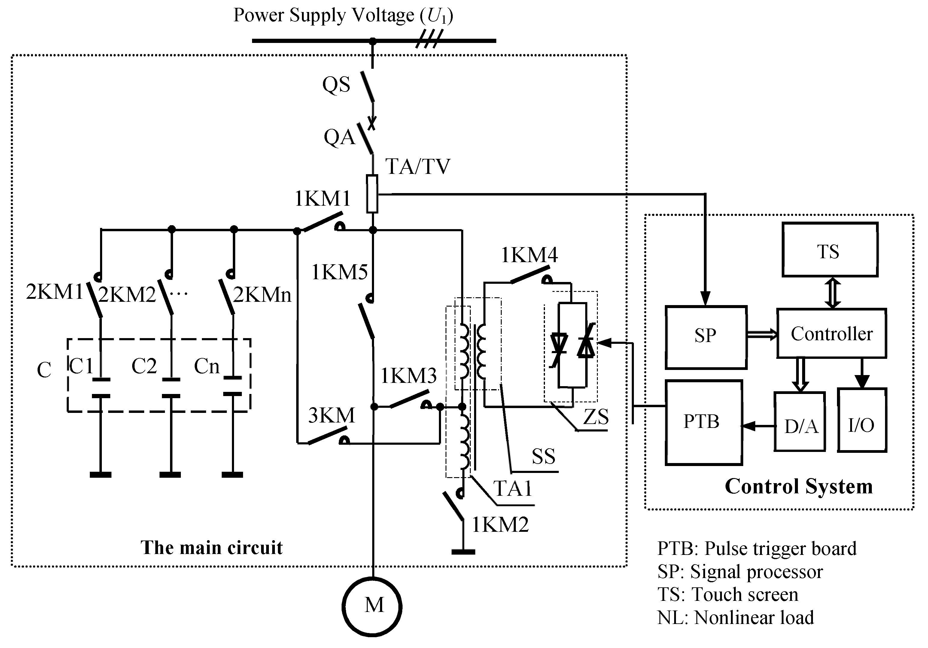
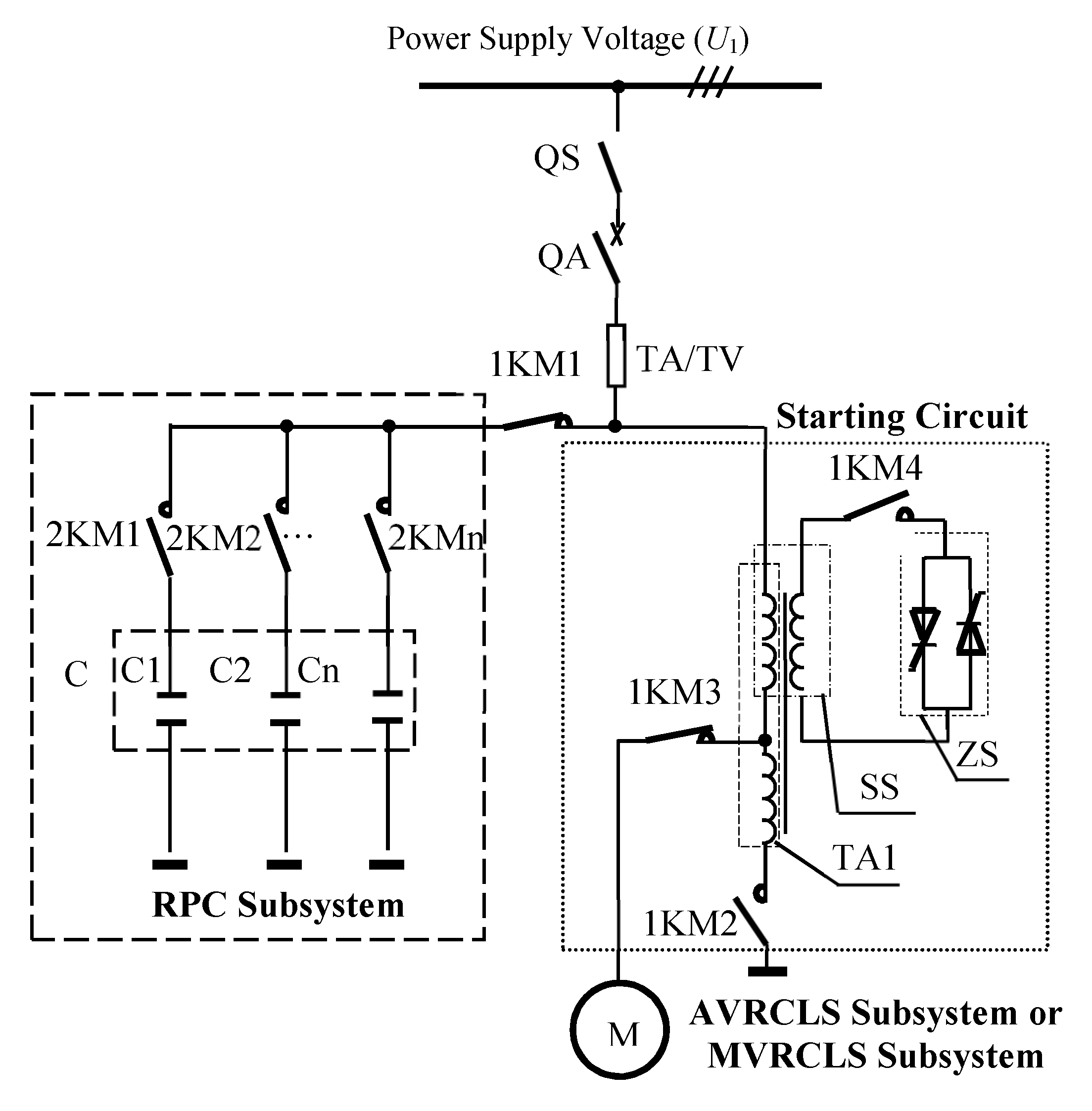
2.2. Topologial Structure

Based on the research findings [28,29,30,31,32] and according to the above current-limiting starting characteristic curve, a device was developed which integrated current-limiting starting, reactive compensation, and harmonic filtering (hereinafter referred to as integrated device). The topological structure of the integrated device is shown in Figure 2.
As shown in Figure 2, QS is a disconnector, QA is a high-voltage circuit-breaker, TA/TV is a current/voltage transformer, TA1 is an autotransformer, SS is a magnetic control reactance transformer, ZS is an impedance transformer, C is a capacitor bank composed of several compensation capacitors (C1, C2,…, Cn), and M is the high-voltage and high-power motor. 1KM1~1KM5, 2KM1-n, and 3KM are high-voltage contactors.
The integrated device consisted of a main circuit and a control system. The main circuit was mainly composed of QS, QA, TA/TV, TA1, SS, ZS, 1KM1~1KM5, 2KM1-n, 3KM, and C. To be specific, the AVRCLS subsystem was made up of QS, QA, TA1, 1KM2, and 1KM 3; the MVRCLS subsystem was made up of QS, QA, SS, ZS, and 1KM3-5; the RPC subsystem was made up of C, 1KM1, and 2KM1-n; and the power filtering subsystem was made up of QS, QA, SS, ZS, 1KM4, 3KM, 2KM1-n, and C.
The core components of the integrated device were TA1 and SS. Based on the principle of magnetic amplifier, the working point of the core in SS is controlled to change its inductance value smoothly. The primary winding of the SS was connected in series with the motor, the secondary winding was connected with ZS, and ZS was a three-phase high impedance inverter composed of six thyristors V1~V6. To go into details, V1, V3, and V5 were connected at the cathode, while V4, V6, and V2 were connected at the anode. The thyristors were driven through phase control; according to the control principle of power electronic conversion technology, A-B, A-C, B-C, B-A, C-A, and C-B corresponded to V1, V3, V5, V4, V6, and V2 respectively. A pair of thyristors were triggered every 60 degrees to realize the impedance transformation of the three-phase high impedance inverter.
The control system consisted of sensor (SP), controller, thyristor pulse trigger board (PTB), touch screen (TS), D/A converter (D/A), and digital input and output (I/O). The control system collected the information of starting current Is of the high-voltage and high-power motor via SP and made control decisions like data processing and starting algorithm via the controller. The results were obtained based on two approaches. The one was D/A, which controlled ZS through PTB, thereby realizing the transformation and continuous control of electromagnetic parameters of SS. The other one was I/O which controlled the dynamic switching of high-voltage contactors in the main circuit. TS communicated with the controller via RS485 (Kunluntongtai, Beijing, China), set the variable status, and displayed running parameters and device working status. The control system was used to coordinate and control the AVRCLS subsystem, MVRCLS subsystem, RPC subsystem, and power filtering subsystem so that these subsystems could perform the function properly. The high-voltage and high-power motor’s current-limiting soft starting with RPC was realized by the AVRCLS subsystem, MVRCLS subsystem, and RPC subsystem. The power filtering subsystem was turned on to filter out harmonics in power system as the starting process terminated.

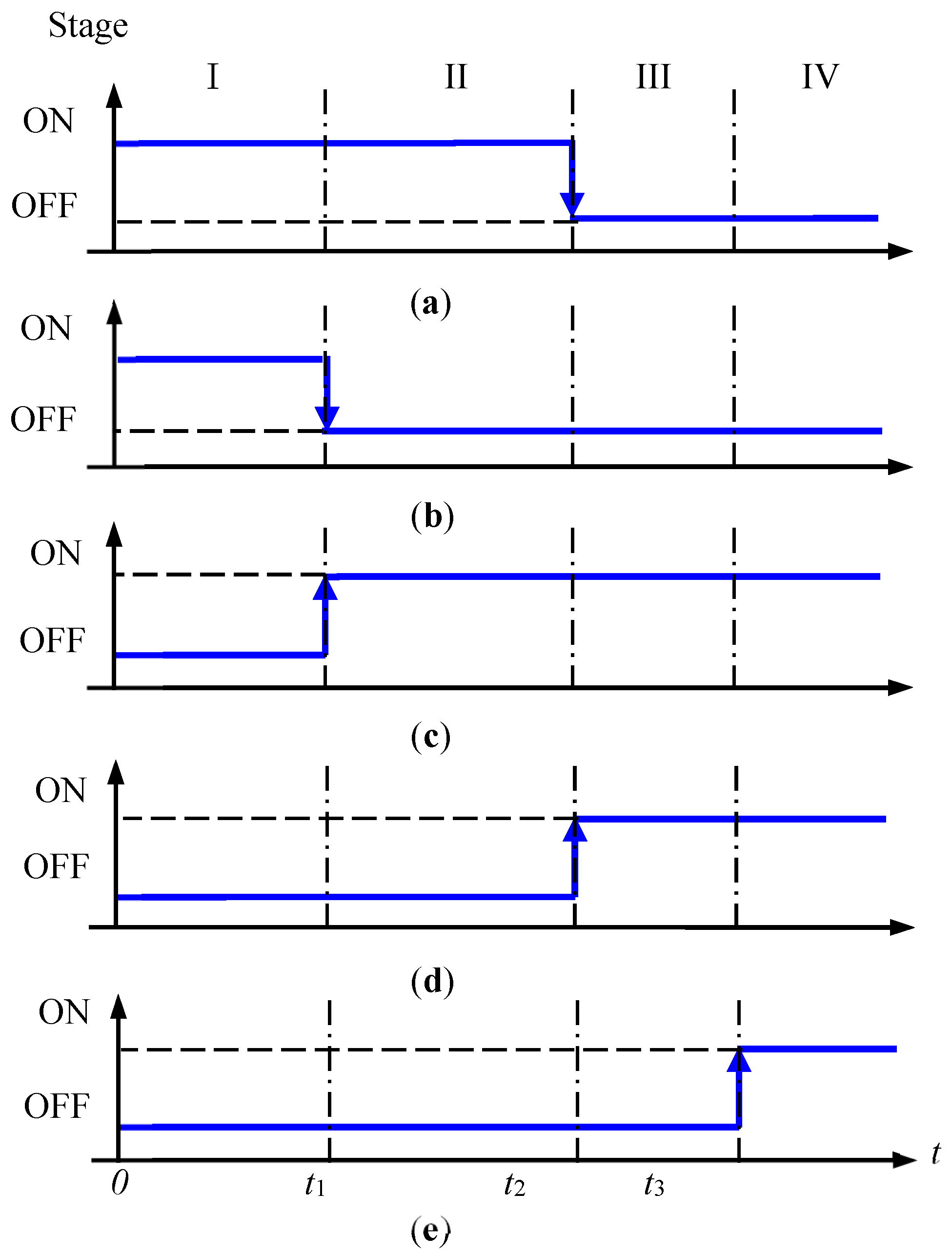
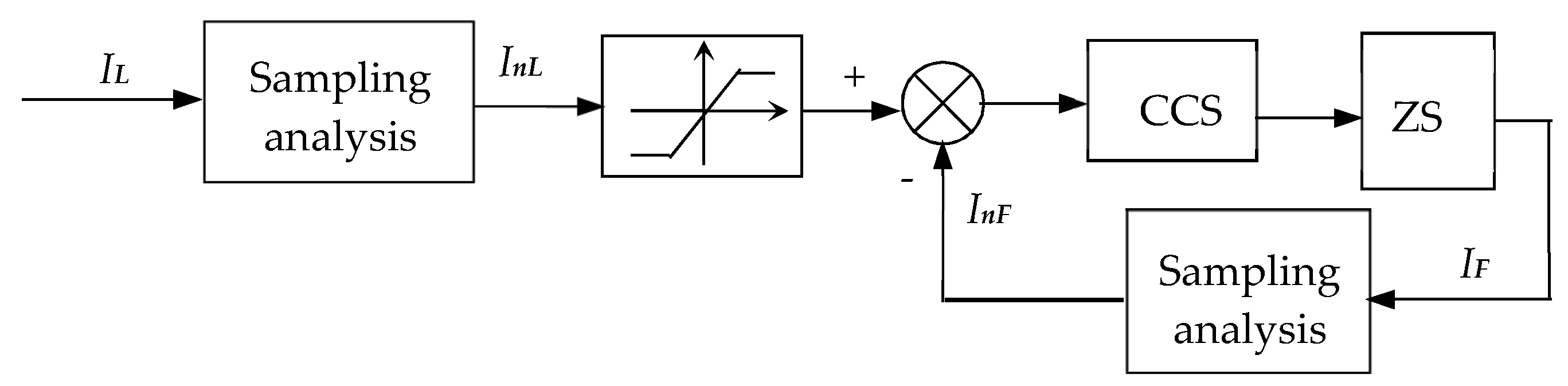
2.3. Functional Logic Switching Strategy

The control system switched the high-voltage contactors according to the topological structure of the integrated device, thereby realizing the current-limiting starting, reactive compensation of a high-voltage and high-power motor, and power harmonic filtering. The chronological order of high-voltage contactors is shown in Figure 3.
In Figure 3, ‘ON’ meant the high-voltage contactor was closed, while ‘OFF’ meant it was open. In stage I (0~t1), the AVRCLS subsystem was turned on; in stage II (t1~t2), the MVRCLS subsystem was turned on; in stage III (t2~t3), the soft starting process of the high-voltage and high-power motor terminated; and in stage IV (t3~), the power filtering subsystem was turned on.
The RPC subsystem provided the reactive power required in the starting process of the motor, thereby increasing the power factor in stage I and stage II. In this process, 2KM1-2KMn switched according to the compensation capacity. In stage IV, it switched according to the resonant frequency of harmonic current that needed to be filtered.

3. Analysis of Mechanisms

In this section, the mechanisms of current-limiting starting, reactive compensation and dynamic harmonic filtering were analyzed in detail.

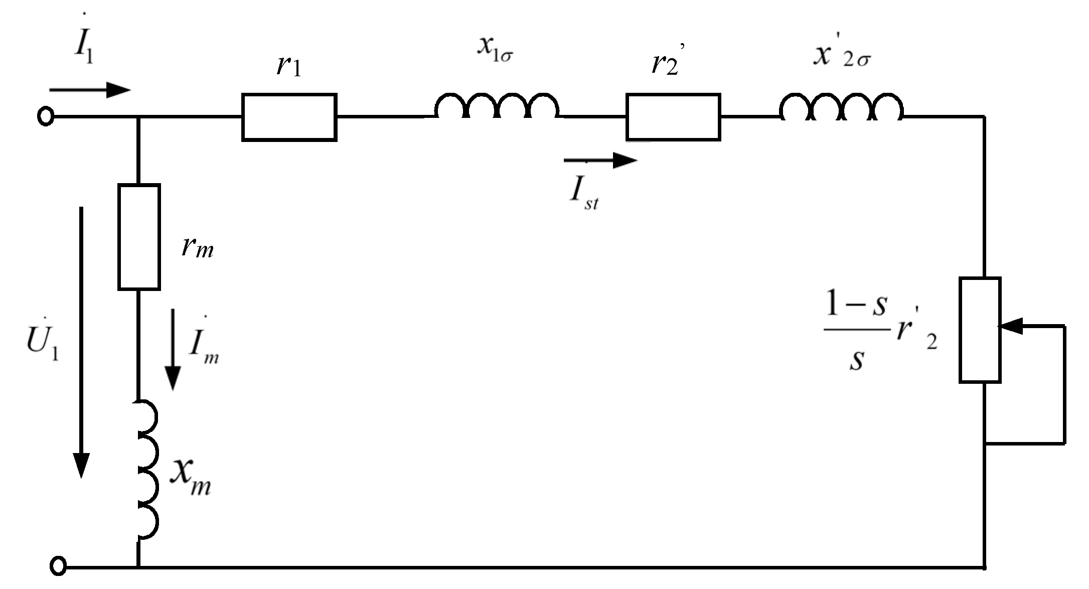
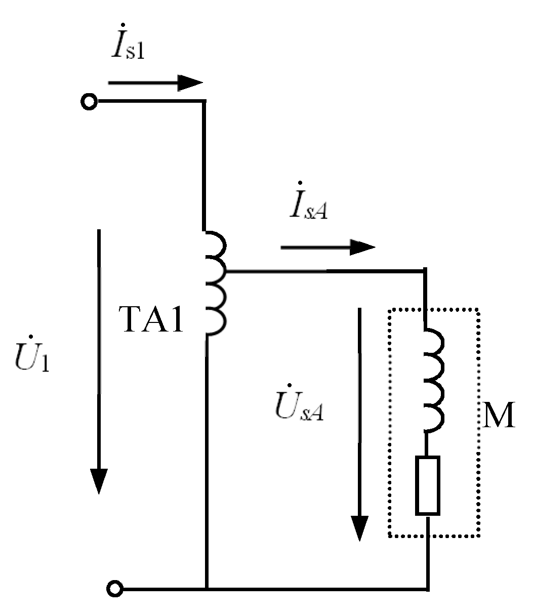
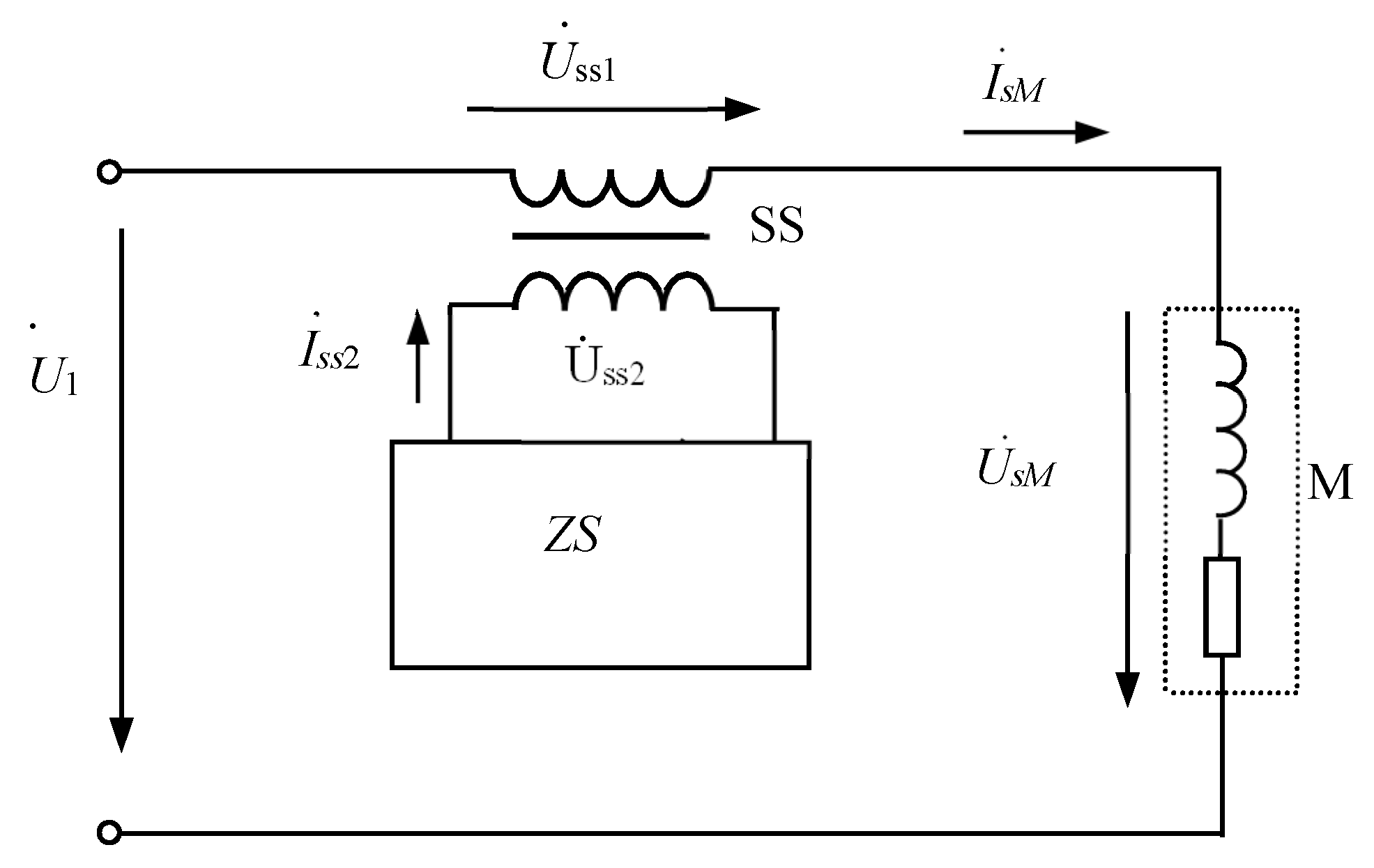
3.1. Mechanism of Direct Starting

Figure 4 showed the Γ-shaped circuit of the motor.
In Figure 4, r1 and x1σ are the stator resistance and stator leakage reactance of the motor, respectively. rm and xm are the excitation resistance and excitation reactance of the motor, respectively. r 2 ' and x 2 σ ' are the converted values of rotor resistance and leakage resistance of the motor respectively. U1 is the root mean square (RMS) of power supply voltage. s is the slip ratio. 1 s s r 2 ' is the mechanical analog resistance.
When the motor started, the speed was 0, s = 1, and the mechanical analog resistance reached 0. So the starting current I s t was only limited by the short-circuit impedance, and its magnitude Ist was as follows:
I s t = U 1 ( r 1 + r 2 ' ) 2 + ( x 1 σ + x ' 2 σ ) 2
It could be known from Equation (2) that as the leakage impedance was small, the starting current was large. When the high-voltage and high-power motor started directly, the voltage at the motor end was U1, and the starting current was Ist.

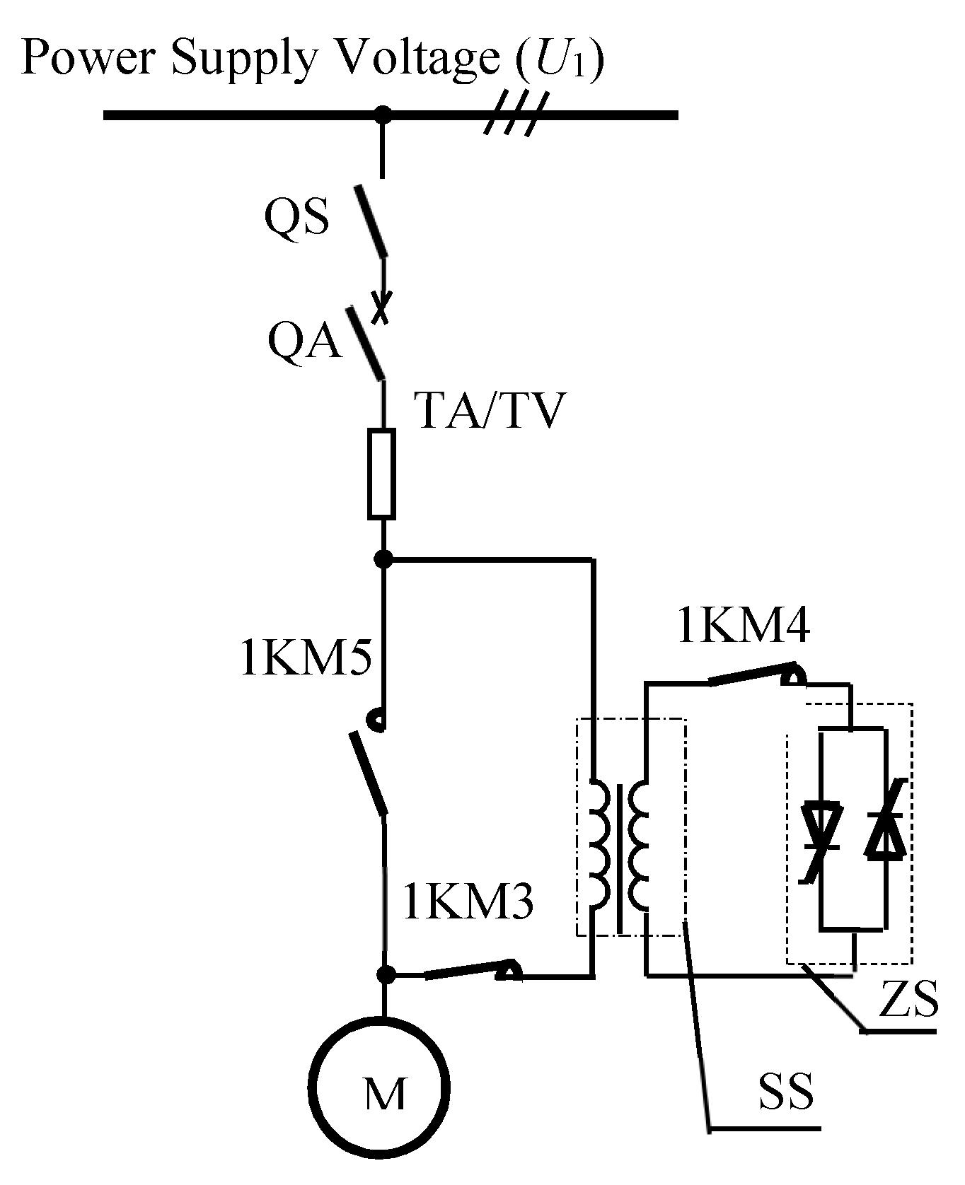
3.2. Mechanism of the AVRCLS Subsystem

The topological structure and equivalent circuit model of the AVRCLS subsystem are shown in Figure 5 and Figure 6, respectively [24].
When the AVRCLS subsystem ran, the transformation ratio of TA1 was set as KA (KA > 1). Let Is1, IsA, U1, and UsA be the input current, output current, input voltage and output voltage of TA1 in the AVRCLS subsystem, respectively, and then we got:
U s A = U 1 k A
where, UsA was equal to δ·Un in Figure 1a. From Figure 6, when the high-voltage and high-power motor started, the starting current Is after being adjusted by autotransformer TA1 was:
I s A = U s A ( r 1 + r 2 ' ) 2 + ( x 1 σ + x ' 2 σ ) 2
From Equations (2)–(4), we got:
I s A = I s t k A
According to Equations (3) and (5), the AVRCLS subsystem could reduce the voltage and limit the current of the motor during starting.

3.3. Mechanism of the MVRCLS Subsystem

The topological structure and equivalent circuit model of the MVRCLS subsystem are shown in Figure 7 and Figure 8, respectively [15].
As shown in Figure 8, the high-voltage winding of SS was the primary side, with Nss1 as the number of turns, Uss1 as the voltage and Iss1 as the current. The high-voltage winding and the motor (voltage: US) were connected in series. Similarly, the low-voltage winding of SS was the secondary side, with Nss2 as the number of turns, Uss2 as the voltage and Iss2 as the current. The low-voltage winding and ZS were also connected in series.
The voltage equation could be obtained from Figure 8:
{ U s M = U 1 U s s 1 U s s 1 = Z s s 1 I s M U s s 2 = Z s s 2 I s s 2
The ratio of the number (n) of turns of high-voltage winding of SS to the number of turns of low-voltage winding was:
n = N s s 1 N s s 2 = U s s 1 U s s 2 = I s s 2 I s M
Then the impedance correlation between the high-voltage winding and low-voltage winding of SS could be formulated as:
Z s s 1 = U s s 1 I s s 1 = n 2 Z s s 2
In the thyristors in ZS work state, the positive and negative half-waves of current waveform of secondary winding were symmetrical, free from direct component and even-order harmonics. According to the Fourier formula, the current of secondary winding could be expressed as [21]:
i s s 2 ( ω t ) = n = 1 , 3 , 5 ( a n cos n ω t + b n sin n ω t )
where,
a 1 = 2 π a π i s s 2 ( ω t ) cos ω t d ( ω t ) = 2 π a π 2 U s s 2 Z s s a cos ω t d ( ω t ) = 2 U s s 2 2 π Z s s a ( cos 2 a 1 )
b 1 = 2 π a π i s s 2 ( ω t ) sin ω t d ( ω t ) = 2 U s s 2 2 π Z s s 2 [ sin 2 a + 2 ( π a ) ]
a 3 = 2 U s s 2 π Z s s 2 [ 1 4 cos 4 a 1 2 cos 2 a + 1 2 ]
b 3 = 2 U s s 2 2 π Z s s 2 [ 1 4 sin 4 a 1 2 sin 2 a ]
where, a is the triggering angle of thyristors. If a 1 > > a 3 , a 3 could be ignored; if b 1 > > b 3 , b 3 could be ignored. Similarly, a 5 ,   a 7 , ... ,   which was far less than a1, and b 5 ,   b 7 , ... ,   which was far less than b1, were ignored. Then Equation (9) was simplified into:
i s s 2 ( ω t ) = a 1 cos ω t + b 1 sin ω t
The effective value of i s s 2 was:
I s s 2 = 1 2 a 1 2 + b 1 2 = U s s 2 π Z s s 2 sin 2 a + ( π a ) sin 2 a + ( π a ) 2
From Equation (15), we got Z s s 1 :
Z s s 1 = U s s 2 I s s 2 = π Z s s 2 sin 2 a + ( π a ) sin 2 a + ( π a ) 2 = f m Z s s 2
where, f m was the coefficient of Z s s 1 with respect to Z s s 2 . The curve of the coefficient f m changing with the triggering angle (a) of the thyristor is shown in Figure 9.
The following conclusions could be drawn from Equations (6) and (16) and Figure 9:
(1) The equivalent impedance Z s s 1 would increase along with the triggering angle of thyristors.
(2) When the triggering angle ranged within 0–140, impedance Z s s 1 changed slowly; when the triggering angle ranged within 140–170 from Figure 9b, the impedance change became obvious; and when the triggering angle ranged within 170–180, a sharp increase was observed in impedance Z s s 1 .
(3) When the triggering angle of thyristors changed, the equivalent impedance of high-voltage winding of SS could be seen as variable impedance, which met Z s s 1 min Z s s 1 Z s s 1 max .
(4) As the triggering angle of thyristors decreased from 180° to 0°, the voltage UsM and the current IsM across the motor could be gradually increased by the MVRCLS subsystem.

3.4. Mechanism of the RPC Subsystem

The high-voltage and high-power motor was a kind of inductive load which could reduce the voltage of power grid by establishing a magnetic field and consuming considerable reactive power. During the starting process of the motor, the power factor gradually increased along with the speed. The compensation capacitor C was connected in parallel with the starting circuit to provide reactive power, which greatly reduced the total current absorbed from the power grid when the motor started. The topological structure and equivalent circuit model of the RPC subsystem are shown in Figure 10 and Figure 11, respectively [27].
Let IR and IA be the active current and reactive current of Is respectively when the motor started, then:
I s = I R 0 ° + I A 90 °
When the RPC subsystem was turned on, the starting current I s Q could be given by:
I s Q = I s + I C 90 ° = I R 0 ° + ( I A 90 ° + I C 90 ° )
where, IC was the reactive current provided by the RPC subsystem.
According to the principle of reactive power compensation, the relationship between the motor current and voltage without and with the RPC subsystem is shown in Figure 12.
The following conclusions could be drawn from Figure 12:
(1) RPC subsystem during the starting of the motor could reduce current, namely, I s Q < I s ;
(2) RPC subsystem during the starting of the motor could increase power factor of the motor, as cos ϕ 2 > cos ϕ 1 .
Based on the empirical approach, this paper assumed that the compensation capacity was correlated with the rated power P N of the motor. Then there existed:
Q = ξ P N
where, ξ denoted the coefficient of relationship which was generally around 0.3 and could be adjusted according to the actual situation.
The optimal switching control strategy for the RPC subsystem was related with the time of switching and grouping of capacitors. According to Equation (19), RPC effect was optimized by grouping switch. In general, the reactive power compensation of the motor required undercompensating, and the power factor was about 0.90–0.95 after compensation.

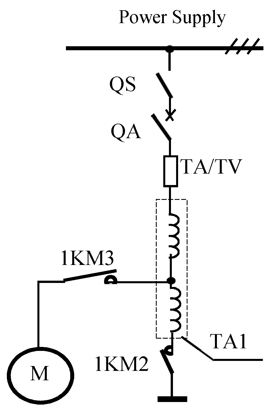
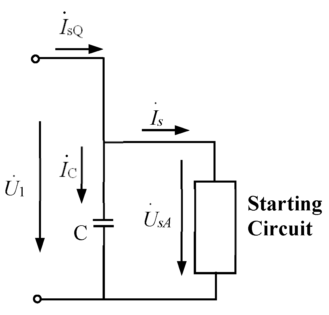
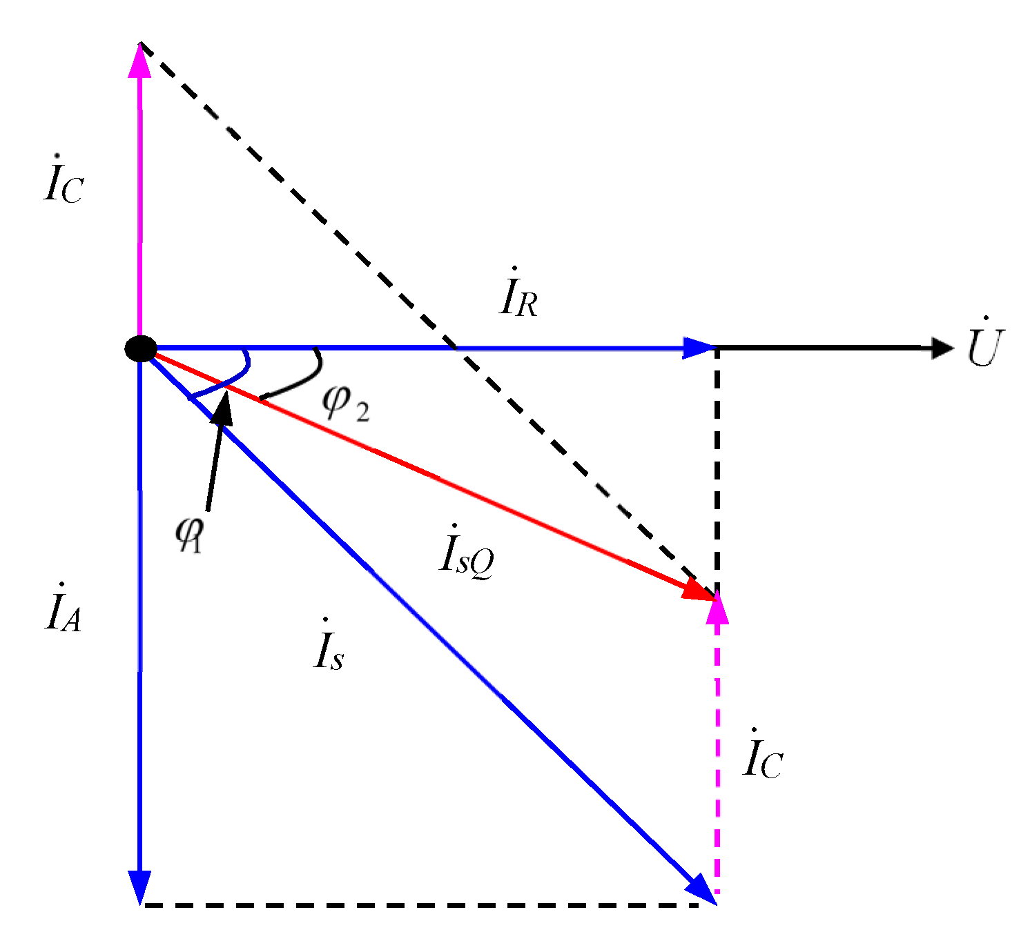
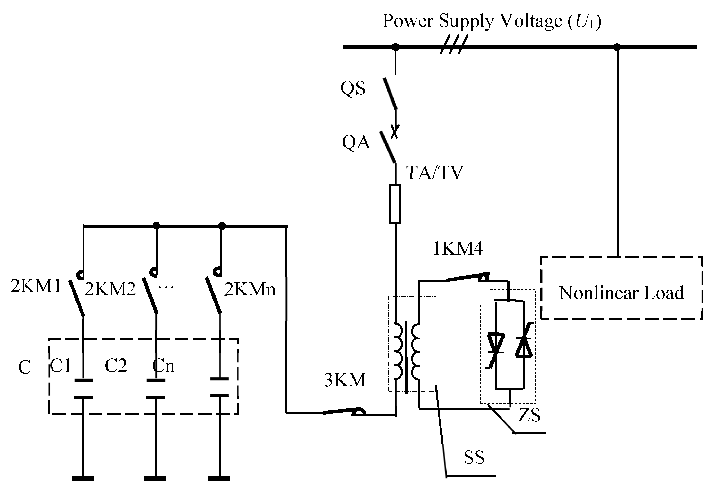
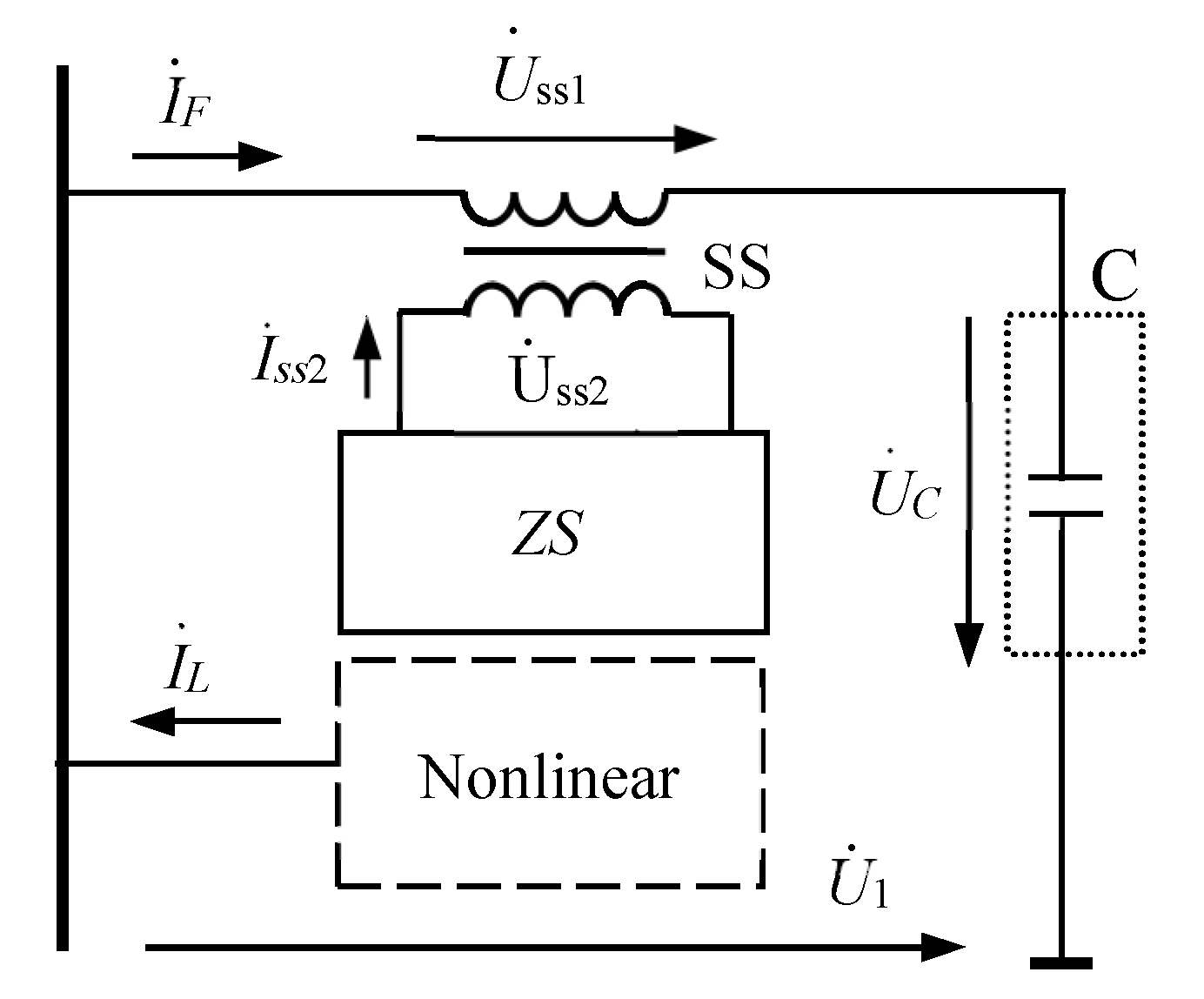
3.5. Mechanism of the Power Filtering Subsystem

The topological structure and equivalent circuit model of the power filtering subsystem are shown in Figure 13 and Figure 14, respectively [29].
As shown in Figure 14, the power filtering subsystem was an LC series filter circuit. The impedances on the high-voltage winding and low-voltage winding of SS as well as the impedance of magnetic coupling were small, so they could all be neglected. Thus, SS showed inductance, then:
{ Z s s 1 X s s 1 = ω L s s 1 Z s s 2 X s s 2 = ω L s s 2
After substituting Equation (20) into Equation (16), the correlation between the equivalent inductance L s s 1 on the high-voltage winding and the triggering angle α of thyristors could be obtained:
L s s 1 = π L s s 2 s i n 2 α + ( π α ) s i n 2 α + ( π α ) 2
Therefore, by controlling the triggering angle of thyristors, Lss1 could be continuously adjusted. In the power system, the part of harmonic current generated by nonlinear load entered the power filtering subsystem, and the other part entered the power grid. When the power filtering subsystem worked normally, the power filtering subsystem resonated at harmonic frequency, forming a low impedance bypass for the harmonic current. In this case, most of the harmonic current was absorbed by the power filtering subsystem.
Let the current offset of the n-th harmonic ΔIn be:
Δ I n = | I n L I n F |
where, InF was the current of the n-th harmonic of the power filtering subsystem, InL was the current of the n-th harmonic on load side, and ΔIn was used to describe the detuning degree of the power filtering subsystem. When the power filtering subsystem worked properly, ΔIn was close to 0. In this case, the filter did not detune harmonics. Nevertheless, when the power filtering subsystem detuned harmonics, the ΔIn of harmonic current increased.
Figure 15 shows the schematic diagram of tuning filter method. Through the synchronous sampling of the currents IF and IL, the n-th harmonic currents InF and InL could be obtained via the Discrete Fourier Transform. The control objective was to make current ΔIn reach the minimum.

4. Simulation and Experimental Evaluation

The direct starting simulation was performed, and then the current-limiting soft starting for a high-voltage and high-power motor was verified by simulation on AVRCLS and MVRCLS with RPC during starting. All the simulations were performed using MATLAB/Simulink (R2018a, The MathWorks, Inc, Natick, MA, USA). Then, a model machine was made to verify the performance of the current-limiting soft starting method. The harmonic filter developed based on the harmonic filtering subsystem was applied to eliminating harmonics of the low-voltage distribution system.

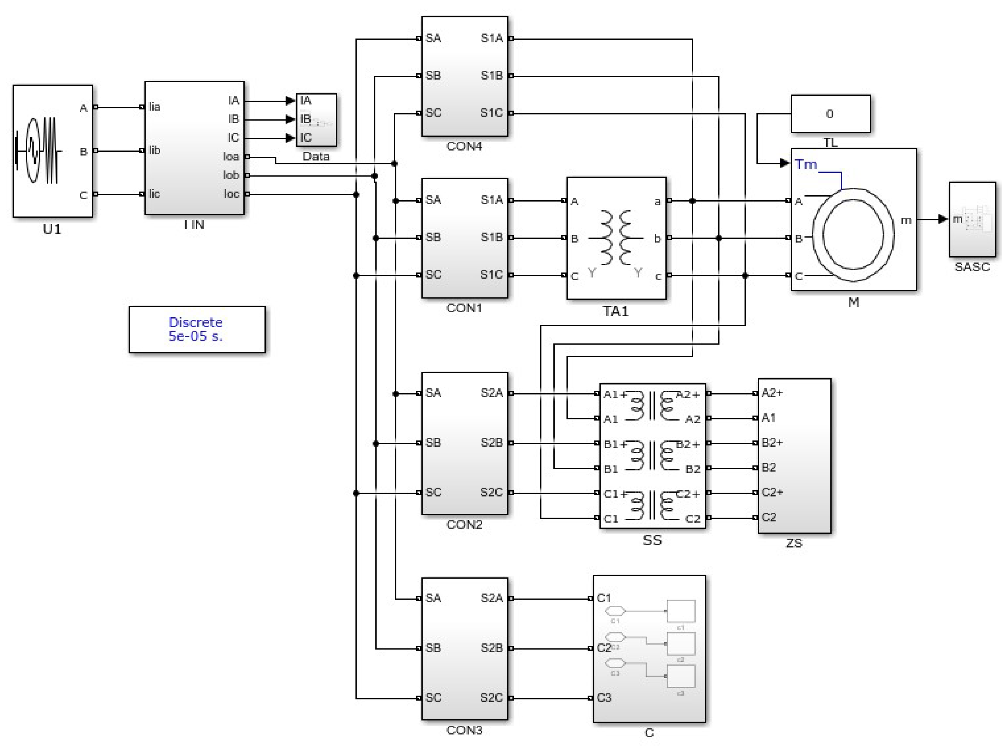
4.1. Simulation System on Current-Limiting Soft Starting

The simulation systems were designed according to the topological structure of the integrated device (Figure 2). AVRCLS and MVRCLS proposed in this paper were used for current-limiting starting through a 10 kV/19,000 kW motor. Direct Starting and Current-limiting Soft Starting were performed with the developed simulation system, as shown in Figure 16.
In Figure 16, the AVRCLS subsystem was made up of CON1, SS, and ZS; the MVRCLS subsystem was made up of CON2, SS, and ZS; the RPC subsystem was made up of CON3 and C. CON1–CON4 correspond to the high voltage contactor in Section 2.2 and the switching strategy in Section 2.3. The parameters of motor were saved and scoped by SASC module.
Three-Phase Source block with 10 kV/50 Hz in Simulink was selected as the power supply voltage (U1). Asynchronous Machine block was selected as the motor whose parameters are listed in Table 1.
The simulation, which mainly focuses on current limiting soft starting, is conducted to compare current limiting soft starting and direct starting, and verify the effect of the soft starting method proposed in this paper.

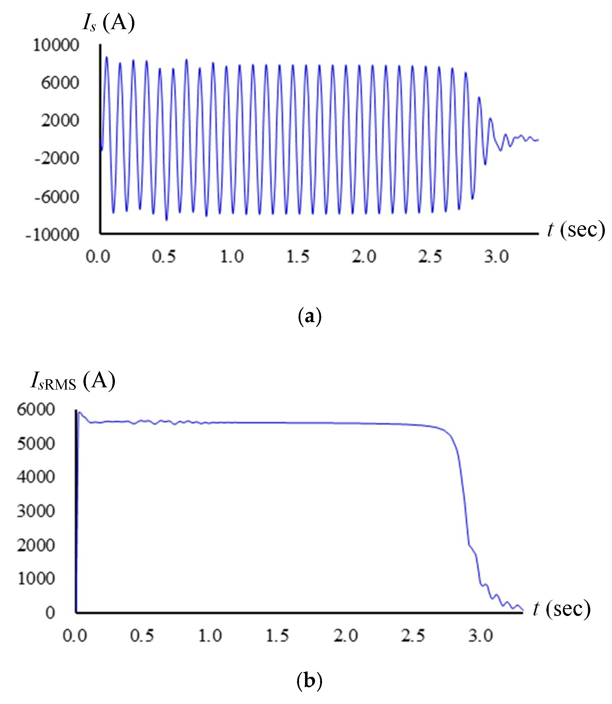
4.2. Simulation Results on Direct Starting

The direct starting simulation was finished with the developed simulation system when only CON4 is switched on.
According to the simulation parameters of the motor in Table 1, speed reference was set to 1500 rpn, load torque was set to 0 N·M, and U1 was applied directly to the motor for direct starting simulation. The simulated results of the current, current RMS, and speed curve are shown in Figure 17.
It could be known from Figure 17a,b that the maximum starting current reached 5627 A, which was about 4.6 times that of the rated current (1253 A). Therefore, the power grid of the motor might be damaged.

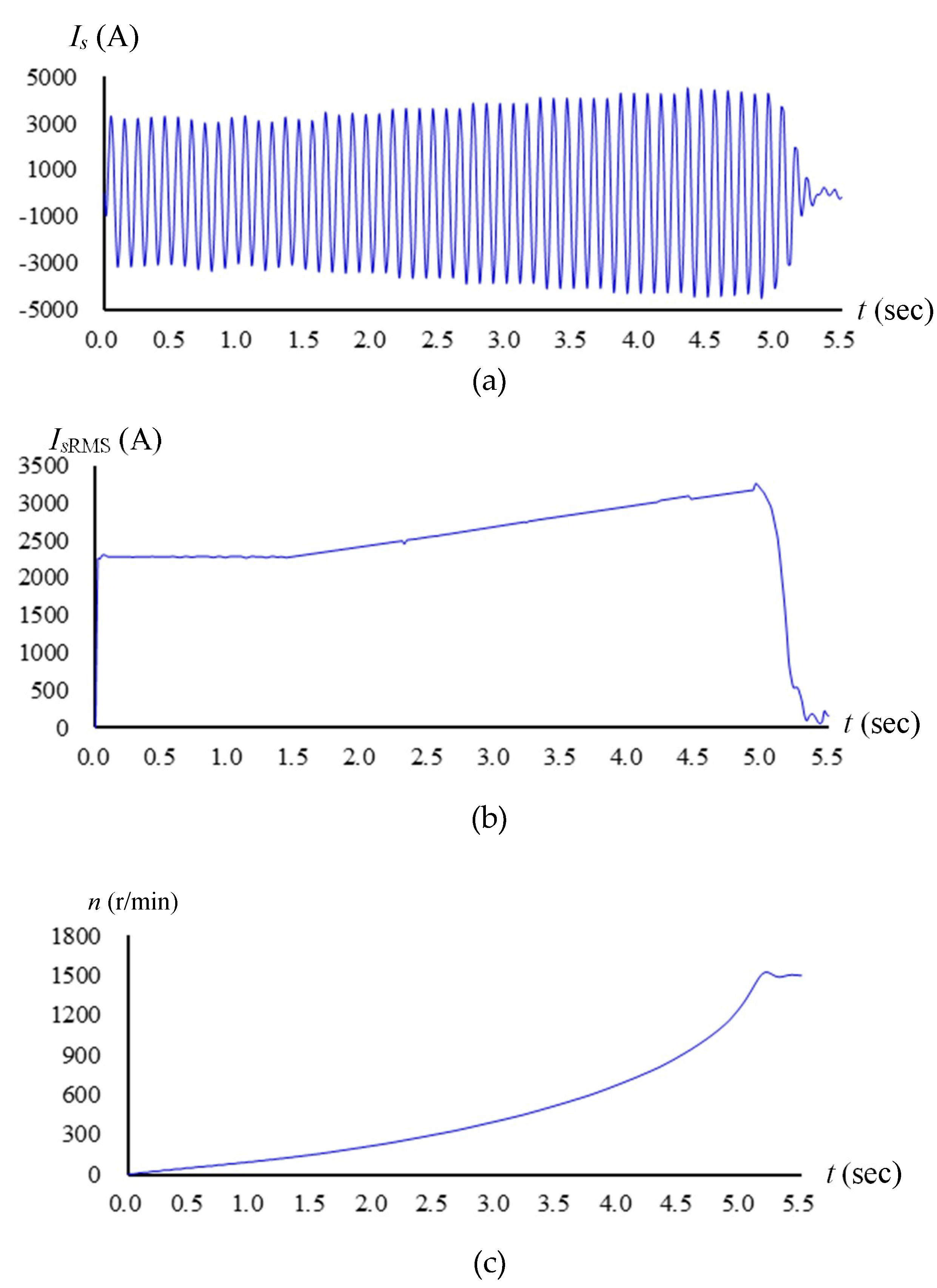
4.3. Simulation Results on Current-limiting Soft Starting

AVRCLS and MVRCLS proposed in this paper were used for current-limiting starting through a 10 kV/19,000 kW motor.
Through assigning different values to δ, t1 and t2, the maximum starting current Ismax of the motor was obtained by simulation. From them, a set of parameters suitable for practical projects could be obtained, and the motor's starting current’s relationship with δ, t1 and t2 are found.
According to functional logic switching strategy, δ was set from 1 to 5 and increments of 0.1 by CON1; t1 was set from 0.1 to 1 and increments of 0.1 by CON2; and t2 was set from 4 to 7 and increments of 0.5 by CON3.
The maximum starting current Ismax of the motor was obtained by assigning different values of δ, t1 and t2. Some of the simulation results are listed in Table 2.
The conclusions drawn from Table 2 were as follows:
(1) The starting current of the motor would be affected by δ, t1 and t2, showing a nonlinear relationship. Among them, t2 made the greatest contribution to the starting current.
(2) Through simulation analysis based on AVRCLS and MVRCLS with RPC, a set of parameters suitable for practical projects could be obtained. For instance, when t1 = 1, t2 = 6 and δ = 0.6, the maximum starting current of 10 kV/119,000 kW motor dropped from 5627 A to 2987 A, which was 46.9% lower than it would be if the motor started directly and was about 2.4 times as large as the rated current (1253 A). The motor’s current curve, current RMS and speed curve of rotor are shown in Figure 18.
AVRCLS and MVRCLS with RPC subsystem were used for current-limiting starting through a 10 kV/19,000 kW YKK1009-4 motor. The RPC subsystem was turned on, providing the reactive power required in the starting process of the motor. The simulation results showed that the maximum starting current was 2432 A, 56.8% lower than that of direct starting and 1.9 times as large as the rated current (1253 A). Besides, the power factor increased to 0.93.

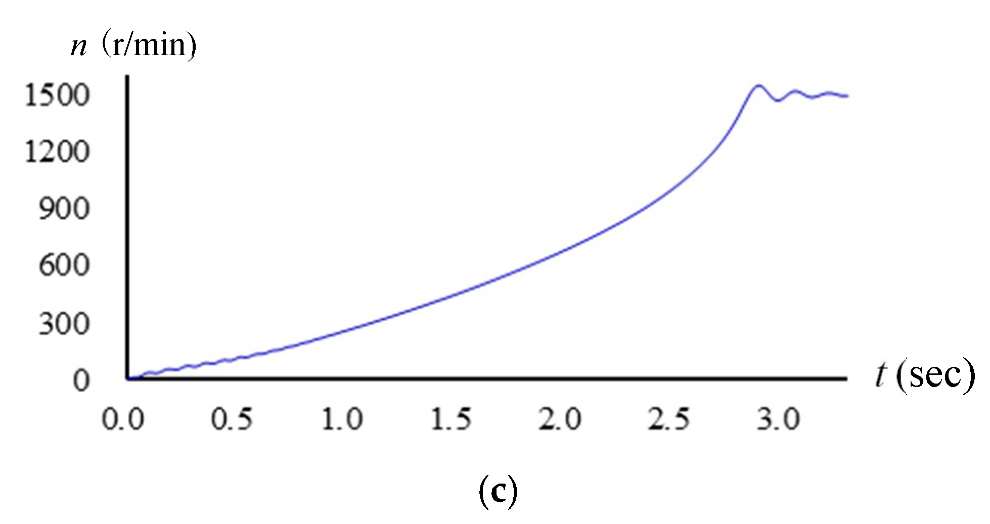
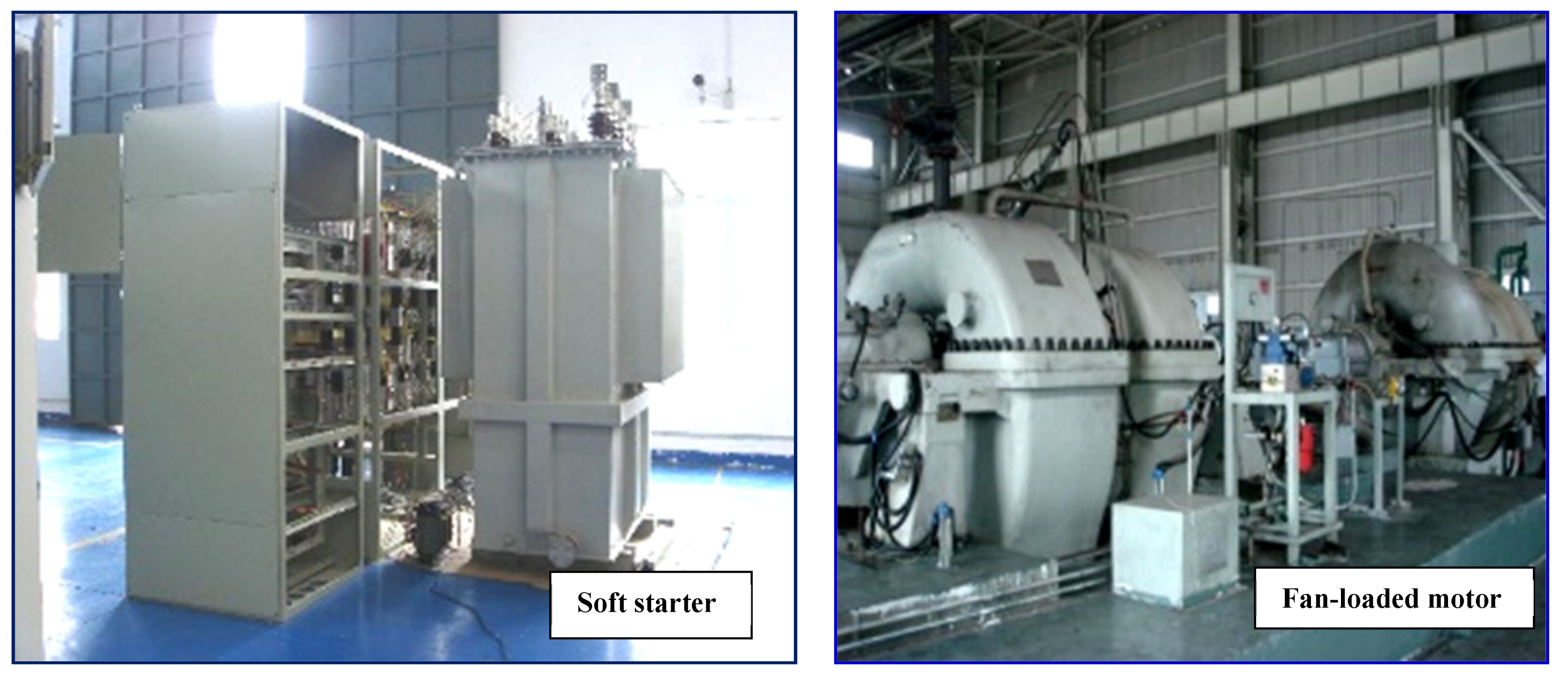
4.4. Experimental Evaluatiom on Soft Starting

With a 10 kV/19,000 kW fan-loaded motor of a steel plant as the subject of the study, a current-limiting soft starter with RPC was designed based on the theoretical findings. The soft starter was manufactured by Dayu Electric Technology Co., Ltd. The fan-loaded motor is shown in Figure 19.
The fan-loaded starting experiment was performed with the soft starter. The starting current of the motor was displayed by touch screen in the control system. The results of motor soft starting are given in Table 3.
During the starting process, the maximum current of motor was 2550 A, about 2 times as large as the rated current of motor (1253 A), and the power factor increased from 0.32 to 0.9. The results agree well with the simulation results.

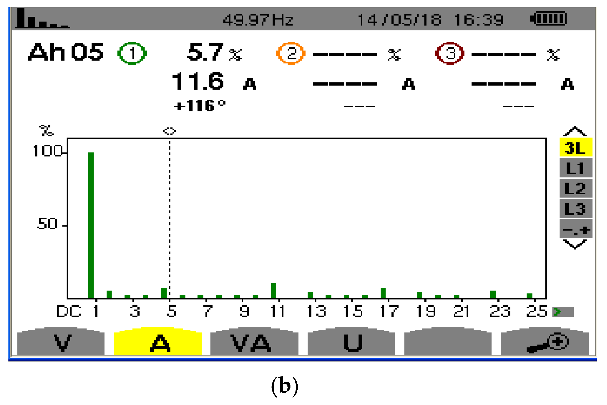
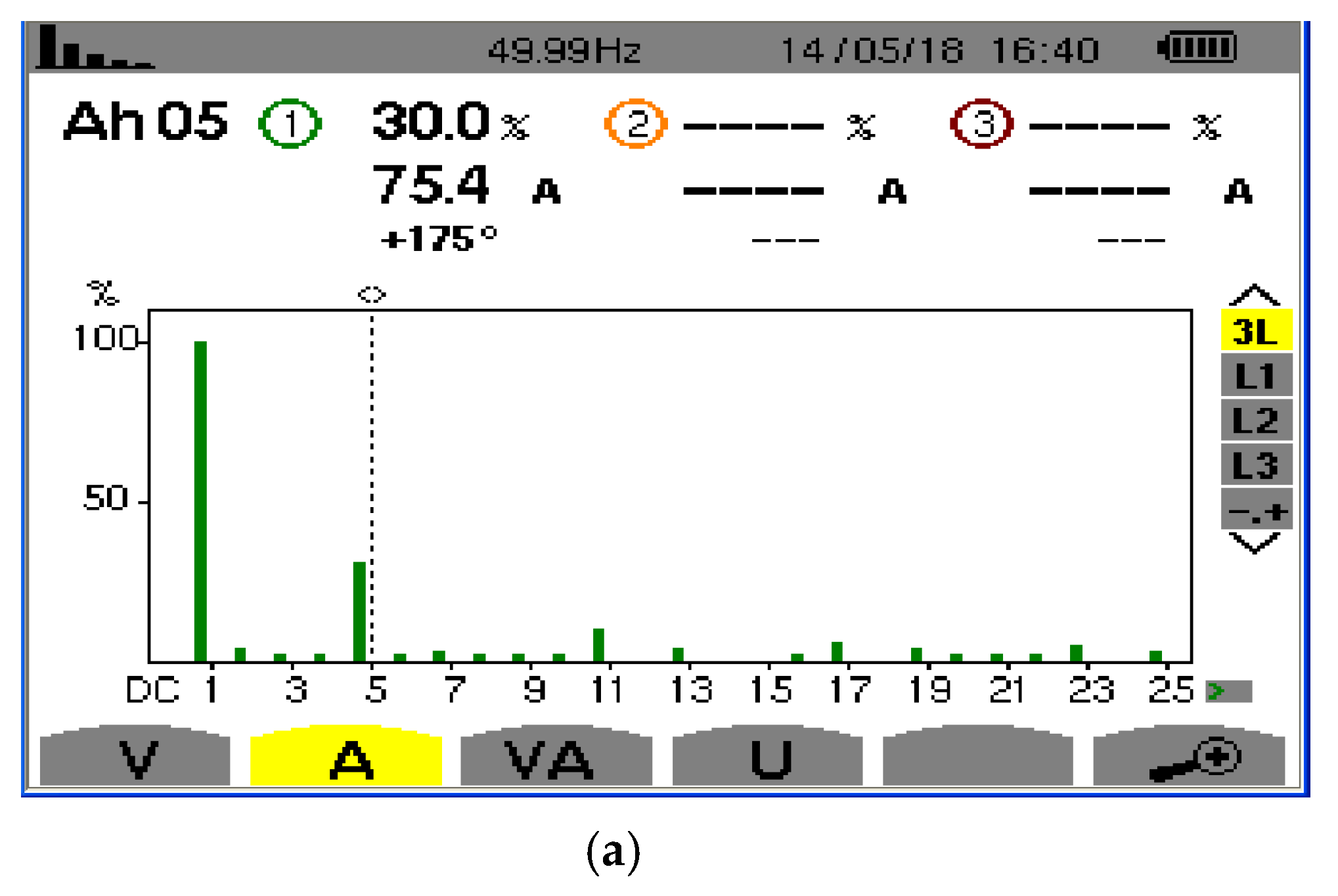
4.5. Experimental Evaluation of the Power Filtering Subsystem

The harmonic filter was developed based on the harmonic filtering subsystem. The harmonic filter was applied to eliminating harmonics of the low-voltage distribution system in China resources cement (Chang Jiang) Co., Ltd, with DC transmission device. The 5th harmonic current (I5) and its total harmonic distortion (THD) are shown in Figure 20.
The filtering performances of the harmonic filter, as shown in Figure 16 (taking phase A as an example), were as follows:
(1) Before filtering (Figure 20a), the 5th harmonic current and its THD of nonlinear load were 75.4 A and 30.0%, respectively.
(2) With the harmonic filter developed in this paper (Figure 20b), the 5th harmonic current and its THD were reduced to 11.6 A and 5.7%, respectively. The harmonic filter absorbed 63.8 A of the 5th harmonic current, reaching an absorption rate of 84.6%. THD was decreased by 81%.
It was found that the harmonic filter could effectively eliminate current harmonics, and reduce the THD of supply currents.

5. Conclusions

This paper has proposed a current-limiting soft starting method which integrates autotransformer voltage reduction–current limiting starting, magnetron voltage regulation–current limiting starting and reactive power compensation during starting for a high-voltage and high-power motor. Specifically speaking, the power filtering subsystem is turned on to filter out harmonics in power system as the starting process terminates. Based on the current-limiting starting characteristic curve, this paper has established the topological structure of the integrated device, analyzed the switching order of high-voltage contactors, and studied the mechanisms of AVRCLS, MVRCLS, RPC, and power filtering. The AVRCLS subsystem and MVRCLS subsystem are able to restrict the starting current of the motor and reduce the current absorbed form power grid. When the motor starts, the RPC subsystem is turned on to provide reactive power, and it increase power factor. As the power filtering subsystem is an LC series filtering circuit, a variable equivalent inductance has been proposed to realize automatic tuning and filtering of harmonics.
The simulation and experimental evaluation have been completed. In particular, the direct starting and current-limiting starting have been performed by developing a simulation system. In addition, a 10 kV/19,000 kW fan-loaded motor of a steel plant has been selected as the object to verify the performance of the current-limiting soft starting method. As indicated by the experimental results, the motor’s starting current is about 2 times as large as its rated current, the power factor is raised to over 0.9 after RPC, and the harmonic filter can effectively eliminate current harmonics and reduce the THD of supply currents.
The authors of the present paper believe that the proposed method will be promising if the related technology is fully developed. The details for realizing the power filtering subsystem in this study can be found in the research results of the authors [27], and as a result are excluded from this paper. Moreover, it is necessary to add a power filtering subsystem and to develop an integrated device in the future research. Hopefully, the research findings in this paper are of great theoretical and practical significance in developing soft starters with independent intellectual property rights and in promoting the development of soft-start technology and industry.

Author Contributions

Y.W. provided the conceptualization, methodology of this manuscript; K.Y. and J.C. provided the experimental evaluation and revised the manuscript in English; Y.Y. support the simulation evaluation and reviewed the manuscript.

Funding

This work was supported by the National Support Program of China 358 (2015BAG20B05), the Zhejiang Province Natural Science Foundation of China (LY14E070003), and the Independent Innovation Fund Project of Wuhan University of Technology (2018-JL-004).

Acknowledgments

The authors thank for the kind help of Dayu Electric Technology Co., Ltd.

Conflicts of Interest

The authors declare no conflict of interest. The funders had no role in the design of the study, in the collection, analyses, or interpretation of data, in the writing of the manuscript, or in the decision to publish the results.

Abbreviations

PLCProgrammable Logic Controller
AVRCLSAutotransformer voltage reduction–current limiting starting
MVRCLSMagnetron voltage regulation–current limiting starting
RPCReactive power compensation
TSTouch screen
D/ADigital analog converter
I/ODigital input and output
RMSRoot mean square

References

  1. Goh, H.H.; Kok, B.C.; Looi, M.S. A study of induction motor starting methods in terms of power quality. In Proceedings of the 3rd Engineering Conference on Advancement in Mechanical and Manufacturing for Sustainable Environment, Kuching, Sarawak, Malaysia, 14–16 April 2010; pp. 18–29. [Google Scholar]
  2. Thankachan, J.; George, S. A novel switching scheme for three phase PWM AC Chopper fed induction motor. In Proceedings of the 2012 IEEE 5th India International Conference on Power Electronics (IICPE), Delhi, India, 6–8 December 2012; pp. 1–4. [Google Scholar]
  3. Zhang, Q.; Tong, J.; Lu, Y.; Liu, B. A simple asynchronous motor soft start method and its application. In Proceedings of the 2017 32nd Youth Academic Annual Conference of Chinese Association of Automation (YAC), Hefei, China, 19–21 May 2017; pp. 1074–1078. [Google Scholar]
  4. Shang, M.; Lin, G.M.; Guo, Q.H.; Sun, Y.T. The boot method analysis of three-phase asynchronous motor. Appl. Mech. Mater. 2013, 401–403, 308–311. [Google Scholar] [CrossRef]
  5. Ming, K.; Wang, X.; Li, Z.; Nie, P. Asynchronous operation characteristics and soft-starting method for the brushless doubly-fed motor. IET Electr. Power Appl. 2017, 11, 1276–1283. [Google Scholar]
  6. Jiang, C.; Rui, Y. Design of a new type of mechanical controllable soft start transmission. J. Mech. Eng. 2017, 53, 83–91. [Google Scholar] [CrossRef]
  7. Zhang, G.; Wang, L.; Huang, Y.; Lu, Y.; Zhu, Y. Half-soft starting control of switched reluctance motor using discrete position signal processing. Cluster Comput. 2017, 20, 3185–3198. [Google Scholar] [CrossRef]
  8. Chen, T.; Song, Z.Y.; Zhan, Y.Q.; Chao, T. Comparison of super large motor starting ways. Value Eng. 2014, 31, 96–98. [Google Scholar]
  9. Corral-Hernandez, J.A.; Antonino-Daviu, J.A. Thorough validation of a rotor fault diagnosis methodology in laboratory and field soft-started induction motors. Chin. J. Electr. Eng. 2018, 4, 66–72. [Google Scholar]
  10. Liu, E.P.; Jia, C.L.; Li, J.; Chen, M.S. Research on the oscillations during the soft starting of induction motor controlled by thyristors. Electr. Drive 2011, 8, 48–51. [Google Scholar]
  11. Xia, Y.; Han, Y.; Xu, Y.; Ai, M. Analyzing temperature rise and fluid flow of high-power-density and high-voltage induction motor in the starting process. IEEE Access 2019, 7, 35588–35595. [Google Scholar] [CrossRef]
  12. Zhao, Y.; Liu, S.; Li, X.; Yang, F.; Zhou, D. Full voltage starting method of high-power asynchronous motor considering electromagnetic transient process. High Voltage Eng. 2013, 39, 464–473. [Google Scholar]
  13. Yuan, Y.; Wang, Y.; Peng, W.; Yan, J. Research on high motor soft starter based on variable reactor. Electr. Power Autom. Equip. 2007, 11, 38–41. [Google Scholar]
  14. Yuan, Y.; Xia, Z.; Wang, Y.; Yuan, P.; Peng, W. A soft starter of three phase asynchronous motor. In Proceedings of the 2007 IEEE Power Electronics Specialists Conference, Orlando, FL, USA, 17–21 June 2007; pp. 563–567. [Google Scholar]
  15. Wang, Y.F.; Yuan, Y.X.; Xu, Y. Research on a novel soft starting method of super high-power and high-voltage motor. Appl. Mech. Mater. 2013, 263–266, 604–609. [Google Scholar] [CrossRef]
  16. Sundareswaran, K.; Nayak, P.S. Ant colony based feedback controller design for soft-starter fed induction motor drive. Appl. Soft Comput. 2012, 12, 1566–1573. [Google Scholar] [CrossRef]
  17. Chang, Y.; Yuan, Y.; Chen, J.; Huang, W. Research and design of an intelligent liquid-state soft starter. In Proceedings of the International Conference on Electrical Control Engineering, Wuhan, China, 25–27 June 2010. [Google Scholar]
  18. Chen, J.; Peng, Y.; Yuan, Y.; Tan, S.; Zhou, S.; Chen, G. Development of magnetron soft start device based on PLC 200. Wuhan Ligong Daxue Xuebao (J. Wuhan Univ. Technol.) 2010, 32, 93–94. [Google Scholar]
  19. Yu, M.; Tian, C.; Chen, B. A novel induction motor soft starter based on magnetically controlled reactor. In Proceedings of the IEEE Conference on Industrial Electronics Applications, Singapore, Singapore, 24–26 May 2006. [Google Scholar]
  20. Hu, H.M.; Mao, C.X.; Lu, J.M.; Yu, Y.X. The torque oscillation study in the motor soft starting process with discrete variable frequency method. In Proceedings of the International Conference on Electrical Machines Systems, Wuhan, China, 17–20 October 2008. [Google Scholar]
  21. Wei, G.; Chu, J.; Gan, S. Starting performance research of a high-power middle-voltage induction motor soft starter based on the on-off transformer. In Proceedings of the IEEE International Symposium on Industrial Electronics, Montreal, Canada, 9–13 July 2006. [Google Scholar]
  22. Yuan, Y.; Xiao, Y. Research on one kind of variable reactor. In Proceedings of the International Workshop on Intelligent Systems Applications, Wuhan, China, 23–24 May 2009. [Google Scholar]
  23. Chang, Y.F.; Yuan, Y.X.; Yan, X.U.; Huang, W.C. Topological structure and impedance conversion analysis of power electronic reactor. Power Electron. 2012, 46, 21–22. [Google Scholar]
  24. Huang, W.; Yuan, Y.; Chang, Y. A novel soft start method based on auto-transformer and magnetic control. In Proceedings of the IEEE International Conference on Industrial Technology, Taipei, Taiwan, 14–17 March 2016. [Google Scholar]
  25. Tan, S.; Zhou, S.; Yuan, Y.; Jiang, X. Design on controller of magnetic controlled soft starting for middle-high voltage motor. In Proceedings of the 2010 The 2nd Conference on Environmental Science and Information Application Technology, Wuhan, China, 17–18 July 2010; pp. 478–481. [Google Scholar]
  26. Tan, S.; Zhang, Z.; Jing, C.; Yuan, Y.; Gang, C. Design on Intelligent Controller of Magnetic Starting for Reactive Compensation. In Proceedings of the International Conference on Applied Informatics and Communication, Xi’an, China, 20–21 August 2011; pp. 600–607. [Google Scholar]
  27. Wang, Y.F.; Yuan, Y.X.; Chang, Y.F.; Yan, X.U. A novel soft starting integration current-limiting, reactive power compensation for super high-power and high-voltage motor filtering. Wuhan Ligong Daxue Xuebao (J. Wuhan Univ. Technol.) 2013, 35, 140–143. [Google Scholar]
  28. Kim, J.-C.; Kwak, S.; Kim, T. Power factor control method based on virtual capacitors matrix rectifiers. IEEE Access 2019, 7, 12484–12494. [Google Scholar] [CrossRef]
  29. Wang, Y.; Yuan, Y.; Chen, J. A novel electromagnetic coupling reactor based passive dynamic tunable function. Energies 2018, 11, 1647. [Google Scholar] [CrossRef]
  30. Jibhakate, C.N.; Chaudhari, M.A.; Renge, M.M. Reactive power compensation using driven by nine switch ac-dc-ac converter. IEEE Access 2017, 6, 1312–1320. [Google Scholar] [CrossRef]
  31. Sarkar, M.N.I.; Meegahapola, L.G.; Datta, M. Reactive power management in renewable grids: A review of grid-codes, renewable generators, support devices, control strategies algorithms. IEEE Access 2018, 6, 41458–41489. [Google Scholar] [CrossRef]
  32. Cortes, B.; Araujo, L.R.; Penido, D.R.R. Passive filters design applied to an electrical system. IEEE Lat. Am. Trans. 2018, 16, 1992–1999. [Google Scholar] [CrossRef]
Figure 1. (a) Voltage characteristic curve; (b) Current characteristic curve.
Energies 12 03068 g001
Figure 2. Topological structure of the integrated device.
Energies 12 03068 g002
Figure 3. (a) Chronological orders of 1KM1,3; (b) Chronological orders of 1KM2; (c) Chronological orders of 1KM4; (d) Chronological orders of 1KM5; (e) Chronological orders of 3KM.
Energies 12 03068 g003
Figure 4. Γ circuit of the motor.
Energies 12 03068 g004
Figure 5. Topological structure of the autotransformer voltage reduction–current limiting starting (AVRCLS) subsystem.
Energies 12 03068 g005
Figure 6. Equivalent circuit model of the AVRCLS subsystem.
Energies 12 03068 g006
Figure 7. Topological structure of the magnetron voltage regulation–current limiting starting (MVRCLS) subsystem.
Energies 12 03068 g007
Figure 8. Equivalent circuit model of the MVRCLS subsystem.
Energies 12 03068 g008
Figure 9. (a) Coefficient f m changing with triggering angle ranged within 0–180; (b) Coefficient f m changing with triggering angle ranged within 140–180.
Energies 12 03068 g009
Figure 10. Topological structure of the reactive power compensation (RPC) subsystem.
Energies 12 03068 g010
Figure 11. Equivalent circuit model of the RPC subsystem.
Energies 12 03068 g011
Figure 12. Relationship between the motor current and voltage without and with the RPC subsystem.
Energies 12 03068 g012
Figure 13. Topological structure of the power filtering subsystem.
Energies 12 03068 g013
Figure 14. Equivalent circuit model of the power filtering subsystem.
Energies 12 03068 g014
Figure 15. Schematic model of tuning filter method.
Energies 12 03068 g015
Figure 16. Simulation system on current-limiting soft starting.
Energies 12 03068 g016
Figure 17. (a) Current curve of motor direct starting; (b) Current root mean square (RMS) of motor with direct starting; (c) Speed curve of motor with direct starting.
Energies 12 03068 g017aEnergies 12 03068 g017b
Figure 18. (a) Current curve of motor with current-limiting soft starting; (b) Current RMS of motor with current-limiting soft starting; (c) Speed curve of motor with current-limiting soft starting.
Energies 12 03068 g018
Figure 19. Soft starter and load of 10 kV/19,000 kW motor (picture).
Energies 12 03068 g019
Figure 20. (a) I5 and total harmonic distortion (THD) before filtering; (b) I5 and THD after filtering.
Energies 12 03068 g020aEnergies 12 03068 g020b
Table 1. Simulation Parameters of the Motor.
Electrical ParametersPower (kVA)19,000
Voltage (kV)10
Frequency (Hz)50
Equivalent Circuit ValuesStator Resistance (Ω)0.124
Stator Leakage inductance (mH)1.125
Rotor Resistance (Ω)0.123
Rotor Leakage inductance (mH)1.125
Mutual inductance (mH)0.716
Mechanical ParametersInertia (kg·m2)703.87
Friction0.00
Pole Pairs2
Table 2. Maximum starting current Isamax as t1, t2 and δ varies.
t1 (s)t2 (s)δIsamax (A)
0.14.50.74729
0.140.74849
0.24.50.45113
0.24.50.54908
0.54.50.74731
14.50.74733
160.62987
Table 3. Results of soft starting of 19,000 kW/10 kV fan-loaded asynchronous motor.
Time for Starting (s)Starting Motor Current (A)State
34 (t1)2550Autotransformer voltage reduction-current limiting starting (STAGE I, 0~t1)
92 (t2)2400Magnetron voltage regulation-current limiting (STAGE II: t1~t2)
145 (t3)2100End of starting process (STAGE III: t2~t3)

