Analysis of the Effect of the Variable Charging Current Control Method on Cycle Life of Li-ion Batteries


Abstract
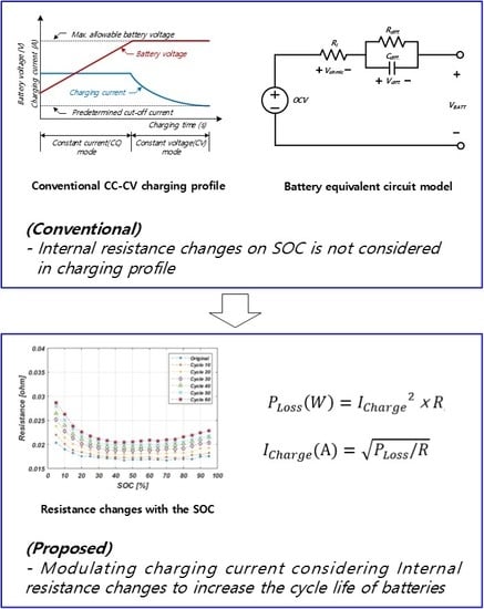
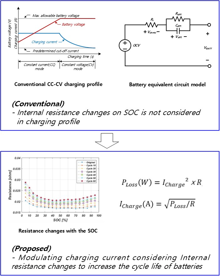
1. Introduction
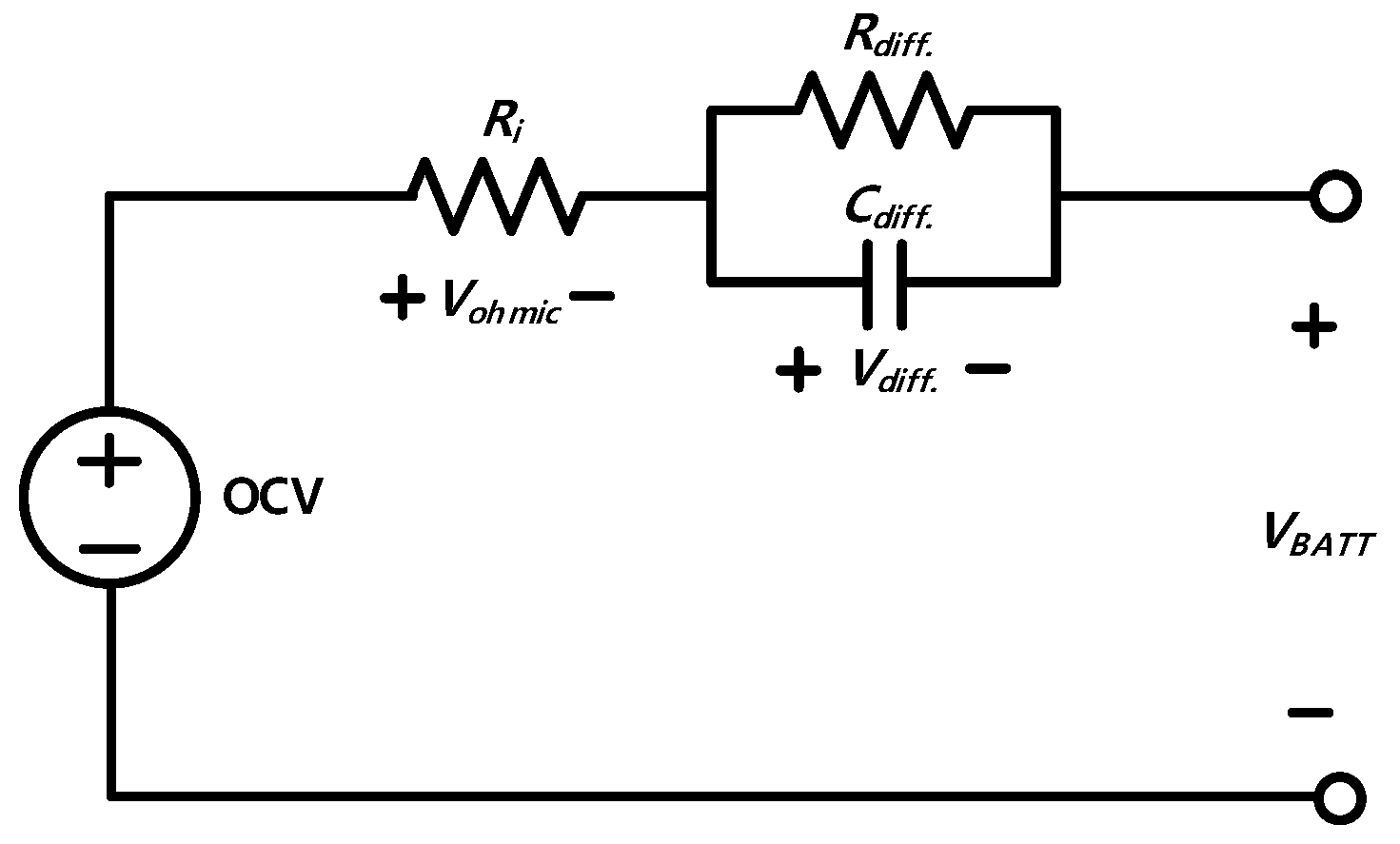
2. Equivalent Circuit Model for SOH Estimation
3. Effect of Internal Heat on SOH of Batteries
4. Proposed Charging Method for Minimizing Battery Degradation
5. Experimental Configuration of the Proposed Algorithm
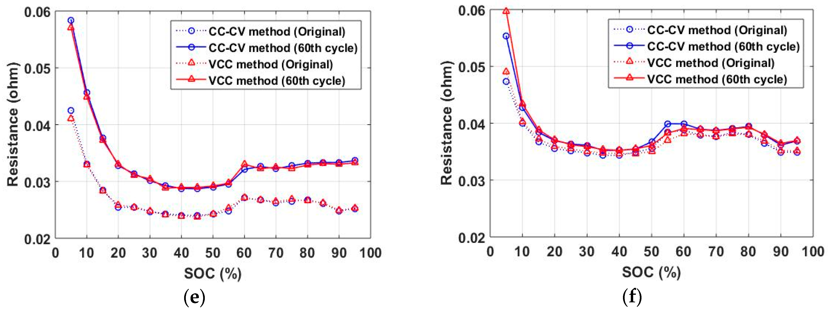
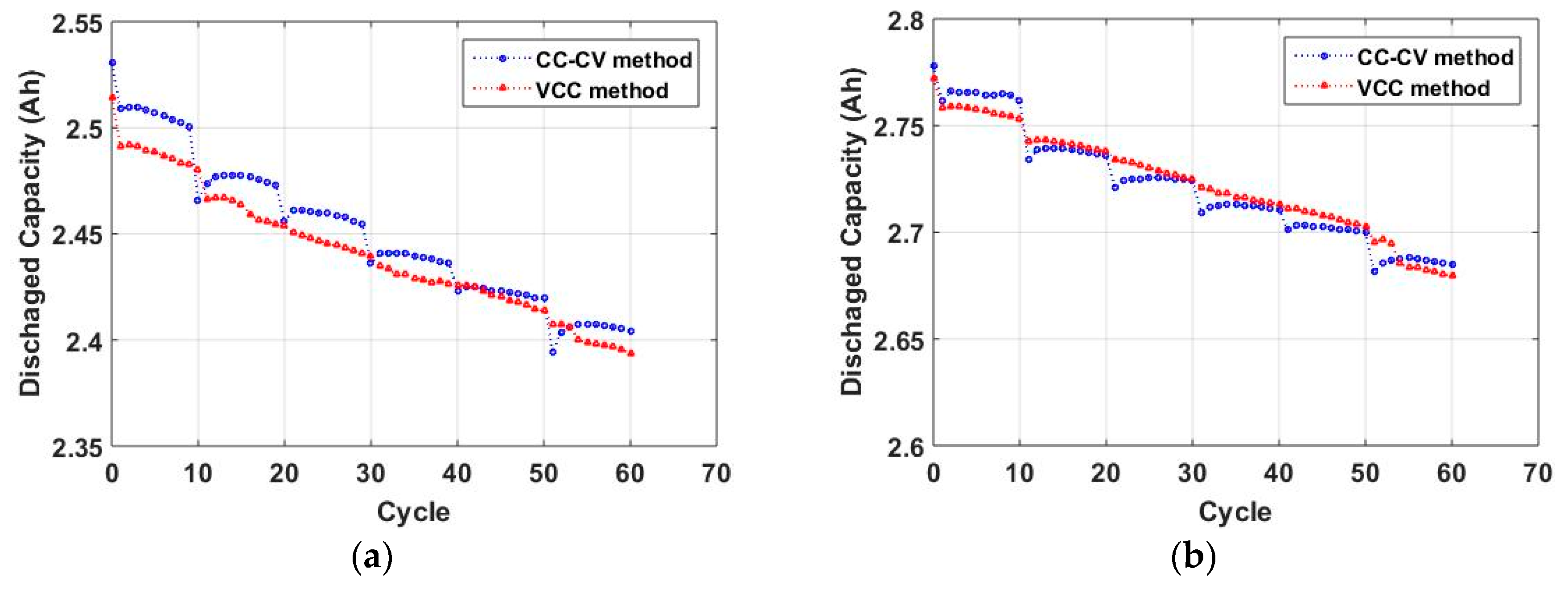
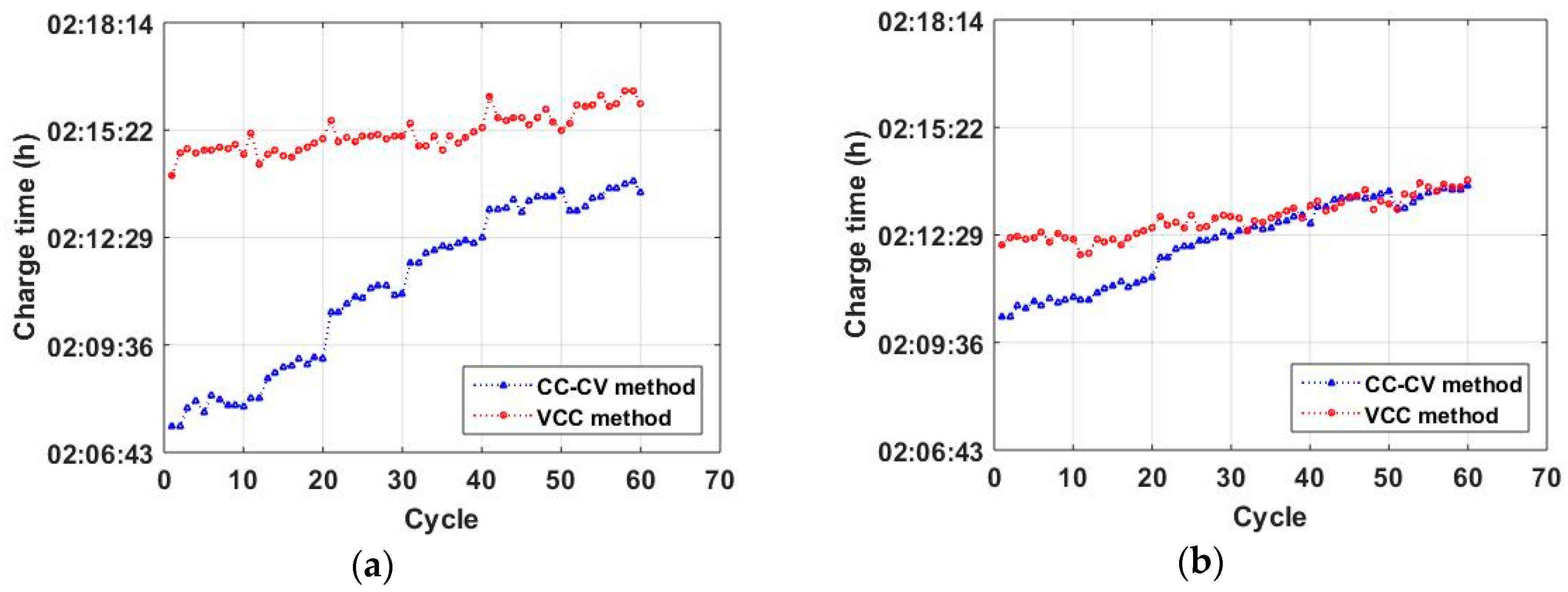
6. Experimental Results
7. Conclusion
Author Contributions
Funding
Conflicts of Interest
References
- Petzi, M.; Kasper, M.; Danzer, M.A. Lithium plating in a commercial lithium-ion battery—A low-temperature aging study. J. Power Sources 2015, 275, 799–807. [Google Scholar] [CrossRef]
- Vetter, J.; Novak, P.; Wagner, M.R.; Veit, C.; Moller, K.C.; Besenhard, J.O.; Winter, M.; Wohlfahrt-Mehrensc, M.; Voglerc, C.; Hammouched, A.; et al. Ageing mechanisms in lithium-ion batteries. J. Power Sources 2005, 147, 269–281. [Google Scholar] [CrossRef]
- Lee, J.H.; Lee, H.M.; Ahn, S. Battery dimensional changes occurring during charge/discharge cycles—Thin rectangular lithium ion and polymer cells. J. Power Sources 2003, 119–121, 833–837. [Google Scholar] [CrossRef]
- Wu, C.; Zhu, C.; Ge, Y.; Zhao, Y. A review on fault mechanism and diagnosis approach for Li-ion batteries. J. Nanomater. 2015, 2015, 8. [Google Scholar] [CrossRef]
- Belov, D.; Yang, M.H. Failure Mechanism of Li-ion Battery at Overcharge Condition. J. Solid State Electrochem. 2008, 12, 885–894. [Google Scholar] [CrossRef]
- Timmermans, J.M.; Nikolian, A.; De Hoog, J.; Gopalakrishnan, R.; Goutam, S.; Omar, N.; Coosemans, T.; Van Mierlo, J.; Warnecke, A.; Sauer, D.U.; et al. Batteries 2020—Lithium-ion battery first and second life ageing, validated battery models, lifetime modelling and ageing assessment of thermal parameters. In Proceedings of the 2016 18th European Conference on Power Electronics and Applications, Karlsruhe, Germany, 5–9 September 2016. [Google Scholar]
- Keil, P.; Jossen, A. Charging protocols for lithium-ion batteries and their impact on cycle life—An experimental study with different 18650 high-power cells. J. Energy Storage 2016, 6, 125–141. [Google Scholar] [CrossRef]
- Zhang, S.S. The effect of the charging protocol on the cycle life of a Li-ion battery. J. Power Sources 2006, 161, 1385–1391. [Google Scholar] [CrossRef]
- Guo, Z.; Liaw, B.Y.; Qiu, X.; Gao, L.; Zhang, C. Optimal charging method for lithium ion batteries using a universal voltage protocol accommodating aging. J. Power Sources 2015, 274, 957–964. [Google Scholar] [CrossRef]
- Zheng, J.; Engelhard, M.H.; Mei, D.; Jiao, S.; Polzin, B.J.; Zhang, J.G.; Xu, W. Electrolyte additive enabled fast charging and stable cycling lithium metal batteries. Nat. Energy 2017, 2, 17012. [Google Scholar] [CrossRef]
- Liu, Y.H.; Luo, Y.F. Search for an optimal rapid-charging pattern for li-ion batteries using the Taguchi approach. IEEE Trans. Ind. Electron. 2010, 57, 3963–3971. [Google Scholar] [CrossRef]
- Botsford, C.; Szczepanek, A. Fast Charging vs. Slow Charging: Pros and cons for the New Age of ElectricVehicles. In Proceedings of the Evs24 International Battery, Hybrid and Fuel Cell Electric Vehicle Symposium, Stavanger, Norway, 13–16 May 2009. [Google Scholar]
- Ikeya, T.; Sawada, N.; Murakami, J.I.; Kobayashi, K.; Hattori, M.; Murotani, N.; Ujiie, S.; Kajiyama, K.; Nasu, H.; Narisoko, H.; et al. Multi-step constant-current charging method for an electric vehicle nickel/metal hydride battery with high-energy efficiency and long cycle life. J. Power Sources 2002, 105, 6–12. [Google Scholar] [CrossRef]
- Gol, E.; Heidary, M.; Kojabadi, H.M. Comparison of Different Battery Charging Methods for Sustainable Energy Storing Systems. In Proceedings of the 26th International Power Systems Conference, Tehran, Iran, 31 October 2011. [Google Scholar]
- Min, H.; Sun, W.; Li, X.; Guo, D.; Yu, Y.; Zhu, T.; Zhao, Z. Research on the optimal charging strategy for Li-ion batteries based on multi-objective optimization. Energies 2017, 10, 709. [Google Scholar] [CrossRef]
- Yilmaz, M.; Krein, P.T. Review of charging power levels and infrastructure for plug-in electric and hybrid vehicles. In Proceedings of the 2012 IEEE International Electric Vehicle Conference, Greenville, SC, USA, 4–8 March 2012. [Google Scholar]
- Shen, W.; Vo, T.T.; Kapoor, A. Charging algorithms of lithium-ion batteries: An overview. In Proceedings of the 2012 7th IEEE Conference on Industrial Electronics and Applications, Singapore, 18–20 July 2012. [Google Scholar]
- Shirk, M.; Wishart, J. Effects of Electric Vehicle Fast Charging on Battery Life and Vehicle Performance. SAE Tech. Paper 2015-01-1190 2015. [Google Scholar] [CrossRef]
- Kettles, D. Electric Vehicle Charging Technology Analysis and Standards; FSEC-CR-1996-15; Florida Solar Energy Center: Cocoa, FL, USA, February 2015. [Google Scholar]
- Wang, D.; Bao, Y.; Shi, J. Online Lithium-Ion Battery Internal Resistance Measurement Applicaton in State-of-Charge Estimation Using the Extended Kalman Filter. Energies 2017, 10, 1284. [Google Scholar] [CrossRef]
- Ecker, M.; Gerschler, J.B.; Vogel, J.; Käbitz, S.; Hust, F.; Dechent, P.; Sauer, D.U. Development of a lifetime prediction model for lithium-ion batteries based on extended accelerated aging test data. J. Power Sources 2012, 215, 248–257. [Google Scholar] [CrossRef]
- Fleischhammer, M.; Waldmann, T.; Bisle, G.; Hogg, B.I.; Wohlfahrt-Mehrens, M. Interaction of cyclic ageing at high-rate and low temperatures and safety in lithium-ion batteries. J. Power Sources 2015, 274, 432–439. [Google Scholar] [CrossRef]
- Liaw, B.Y.; Roth, E.P.; Jungst, R.G.; Nagasubramanian, G.; Case, H.L.; Doughty, D.H. Correlation of Arrhenius behaviors on power and capacity fades, impedance, and static heat generation in lithium ion cells. J. Power Sources 2003, 119, 874–886. [Google Scholar] [CrossRef]
- Onda, K.; Ohshima, T.; Nakayama, M.; Fukuda, K.; Araki, T. Thermal behavior of small lithium-ion battery during rapid charge and discharge cycles. J. Power Sources 2006, 158, 535–542. [Google Scholar] [CrossRef]
- Abdollahi, A.; Han, X.; Avvari, G.V.; Raghunathan, N.; Balasingam, B.; Pattipati, K.R.; Bar-Shalom, Y. Optimal battery charging, Part 1: Minimizing time-to-charge, energy loss, and temperature rise for OCV-resistance battery model. J. Power Sources 2016, 303, 388–398. [Google Scholar] [CrossRef]
- FreedomCAR Battery Test Manual for Power-Assist Hybrid Electric Vehicles. Available online: https://avt.inl.gov/sites/default/files/pdf/battery/freedomcar_manual_04_15_03.pdf (accessed on 22 June 2019).
- Seaman, A.; Dao, T.-S.; McPhee, J. A survey of mathematics-based equivalent-circuit and electrochemical battery models for hybrid and electric vehicle simulation. J. Power Sources 2014, 256, 410–423. [Google Scholar] [CrossRef]
- Lai, X.; Zheng, Y.; Sun, T. A comparative study of different equivalent circuit models for estimating state-of-charge of lithium-ion batteries. Electrochim. Acta 2017, 259, 566–577. [Google Scholar] [CrossRef]
- Qian, K.; Huang, B.; Ran, A.; He, Y.B.; Li, B.; Kang, F. State of health (SOH) evaluation on lithium ion battery by simulating the voltage relaxation curves. Electrochim. Acta 2019, 303, 183–191. [Google Scholar] [CrossRef]
- Kwon, S.J.; Lee, S.E.; Lim, J.H.; Choi, J.H.; Kim, J.H. Performance and Life Degradation Characteristics Analysis of NCM LIB for BESS. Electronics 2018, 7, 406. [Google Scholar] [CrossRef]
- Lu, Z.; Yu, X.L.; Wei, L.C.; Cao, F.; Zhang, L.Y.; Meng, X.Z.; Jin, L.W. A comprehensive experimental study on temperature-dependent performance of lithium ion battery. Appl. Therm. Eng. 2019, 158, 113800. [Google Scholar] [CrossRef]
- Yang, J.; Xia, B.; Huang, W.; Fu, Y.; Mi, C. Online state of health estimation for lithium ion batteries using constant voltage charging current analysis. Appl. Energy 2018, 212, 1589–1600. [Google Scholar] [CrossRef]


| Characteristics | INR 25R | INR 29E |
|---|---|---|
| Rated voltage | 3.60 V | 3.65 V |
| Maximum continuous discharge current | 20 A | 2.750 A |
| Rated capacity | 2500 mAh | 2750 mAh |
| Cut-off voltage | 4.20 V (Charge) 2.50 V (Discharge) | 4.20 V (Charge) 2.50 V (Discharge) |
| Materials | C (Negative) LiCoNiAlO2 (NCA) | C (Negative) LiNiMnCoO2 (NMC) |
| SOC (%) | INR 25R (NCA) | INR 29E (NMC) | ||
|---|---|---|---|---|
| DCIR (ohm) | Current (A) | DCIR (ohm) | Current (A) | |
| 100 | 0.0252 | 1.2258 | 0.0349 | 1.3991 |
| 95 | 0.0252 | 1.2327 | 0.0349 | 1.3991 |
| 90 | 0.0248 | 1.2431 | 0.0349 | 1.3988 |
| 85 | 0.0261 | 1.2111 | 0.0364 | 1.3693 |
| 80 | 0.0268 | 1.1962 | 0.0380 | 1.3412 |
| 75 | 0.0265 | 1.2015 | 0.0384 | 1.3334 |
| 70 | 0.0262 | 1.2084 | 0.0377 | 1.3468 |
| 65 | 0.0268 | 1.1963 | 0.0379 | 1.3429 |
| 60 | 0.0271 | 1.1893 | 0.0388 | 1.3276 |
| 55 | 0.0248 | 1.2433 | 0.0384 | 1.3334 |
| 50 | 0.0242 | 1.2570 | 0.0356 | 1.3861 |
| 45 | 0.0240 | 1.2632 | 0.0349 | 1.3991 |
| 40 | 0.0241 | 1.2619 | 0.0344 | 1.4101 |
| 35 | 0.0243 | 1.2555 | 0.0343 | 1.4102 |
| 30 | 0.0247 | 1.2464 | 0.0348 | 1.4010 |
| 25 | 0.0254 | 1.2269 | 0.0351 | 1.3947 |
| 20 | 0.0255 | 1.2268 | 0.0356 | 1.3859 |
| 15 | 0.0285 | 1.1589 | 0.0367 | 1.3649 |
| 10 | 0.0331 | 1.0757 | 0.0400 | 1.3073 |
| 5 | 0.0425 | 0.9492 | 0.0473 | 1.2012 |
| 0 | 0.0425 | 0.9439 | 0.0473 | 1.2012 |
| Battery Types and Cycles | CC-CV Method | VCC Method | |||
|---|---|---|---|---|---|
| Capacity (Ah) | Growth Rate (%) | Capacity (Ah) | Growth Rate (%) | ||
| 25R (NCA) | Original | 2.5303 | −4.993 | 2.5143 | −4.804 |
| 60th cycle | 2.4039 | 2.3935 | |||
| 29E (NMC) | Original | 2.7781 | −3.353 | 2.7722 | −3.334 |
| 60th cycle | 2.6850 | 2.6798 | |||
© 2019 by the authors. Licensee MDPI, Basel, Switzerland. This article is an open access article distributed under the terms and conditions of the Creative Commons Attribution (CC BY) license (http://creativecommons.org/licenses/by/4.0/).
Share and Cite
Cho, I.-H.; Lee, P.-Y.; Kim, J.-H. Analysis of the Effect of the Variable Charging Current Control Method on Cycle Life of Li-ion Batteries. Energies 2019, 12, 3023. https://doi.org/10.3390/en12153023
Cho I-H, Lee P-Y, Kim J-H. Analysis of the Effect of the Variable Charging Current Control Method on Cycle Life of Li-ion Batteries. Energies. 2019; 12(15):3023. https://doi.org/10.3390/en12153023
Chicago/Turabian StyleCho, In-Ho, Pyeong-Yeon Lee, and Jong-Hoon Kim. 2019. "Analysis of the Effect of the Variable Charging Current Control Method on Cycle Life of Li-ion Batteries" Energies 12, no. 15: 3023. https://doi.org/10.3390/en12153023
APA StyleCho, I.-H., Lee, P.-Y., & Kim, J.-H. (2019). Analysis of the Effect of the Variable Charging Current Control Method on Cycle Life of Li-ion Batteries. Energies, 12(15), 3023. https://doi.org/10.3390/en12153023