Island DC Microgrid Hierarchical Coordinated Multi-Mode Control Strategy


Abstract
:1. Introduction
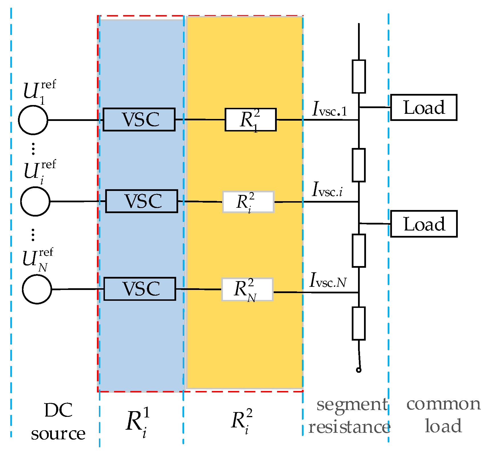
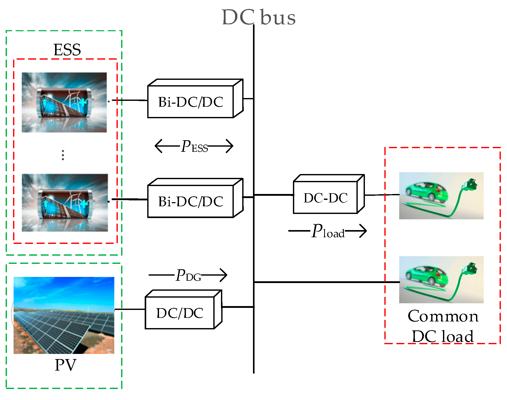
2. DC Microgrid Structure
- (1)
- Photovoltaic array (PV): Integrated into the DC microgrid bus via a one-way DC/DC converter. PV usually adopts the maximum power point tracking (MPPT) mode to fully utilize PV energy.
- (2)
- Energy storage system (ESS): The energy storage system utilizes multiple group battery energy storage (BES) to meet generation and load fluctuation and integrates this with the DC microgrid bus via a two-way DC/DC converter to adjust the power balance of the system.
- (3)
- Common DC load: The common DC load can be integrated into the DC microgrid bus. In addition, it is possible to carry out constant voltage control for important loads through a double closed-loop DC/DC control system. In this way, the voltage fluctuation is reduced and power-supply stability is improved.
- (4)
- Direct current/direct current converter (DC/DC): This is utilized to achieve connections between various generation units in the grid and important loads, which facilitates power exchange of various units.
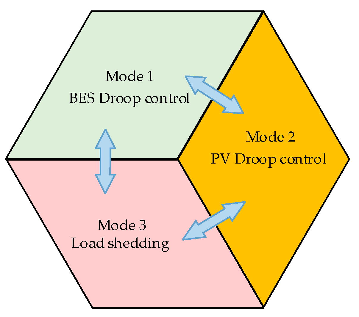
3. Multi-Mode of Island DC Microgrid
- (1)
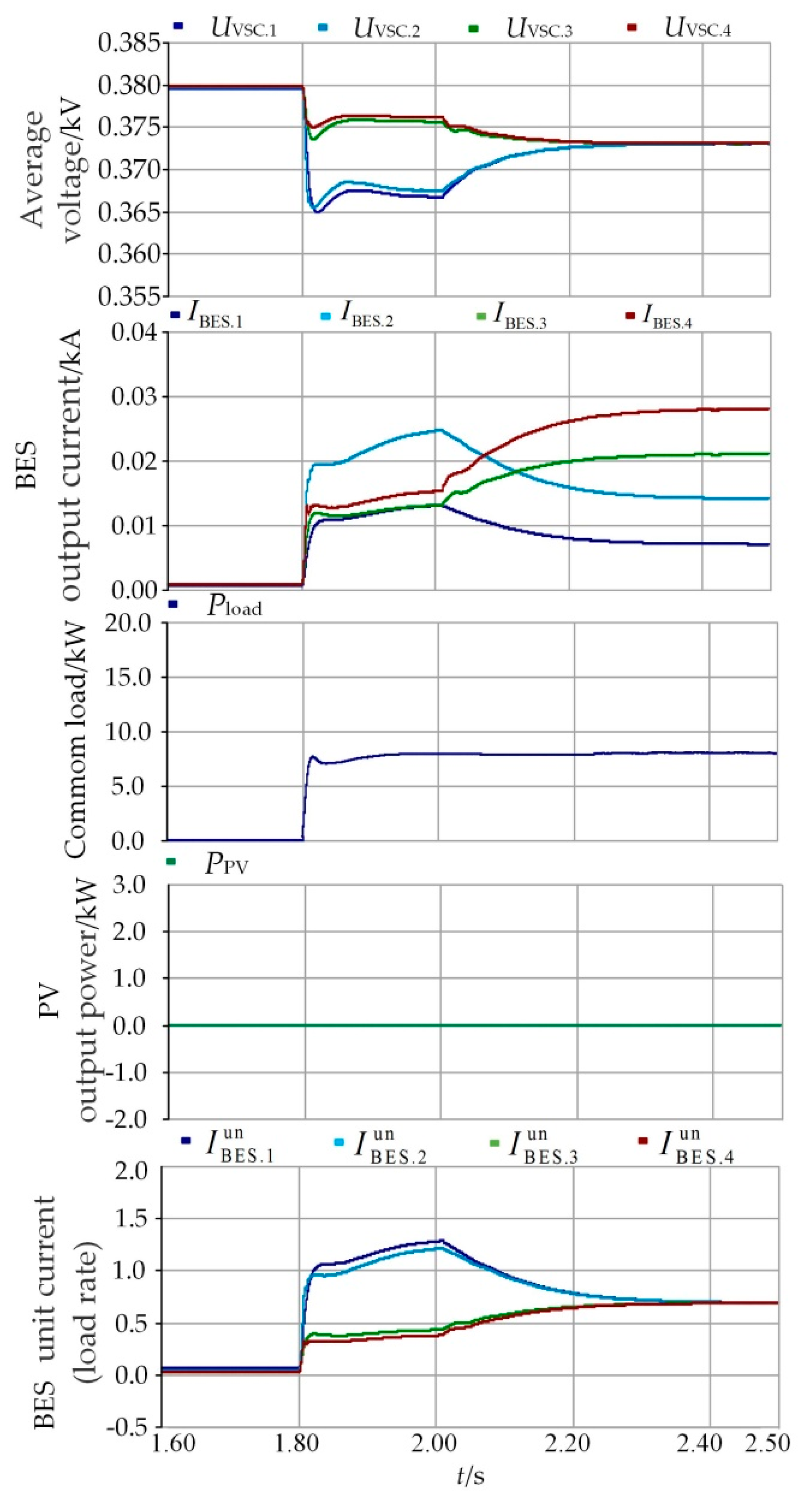
- Mode 1: PV utilizes MPPT control to fully use the photovoltaic energy and maintain a power balance in the system with the help of BES. The power relationship between photovoltaic energy and storage load in the system at this point is indicated by the following formula:where PBES.i refers to the developed power of BES i, indicates the maximum power point tracking power of PV j, represents the common DC overall load of the system, and PL indicates the power consumed by line resistance.
- (2)
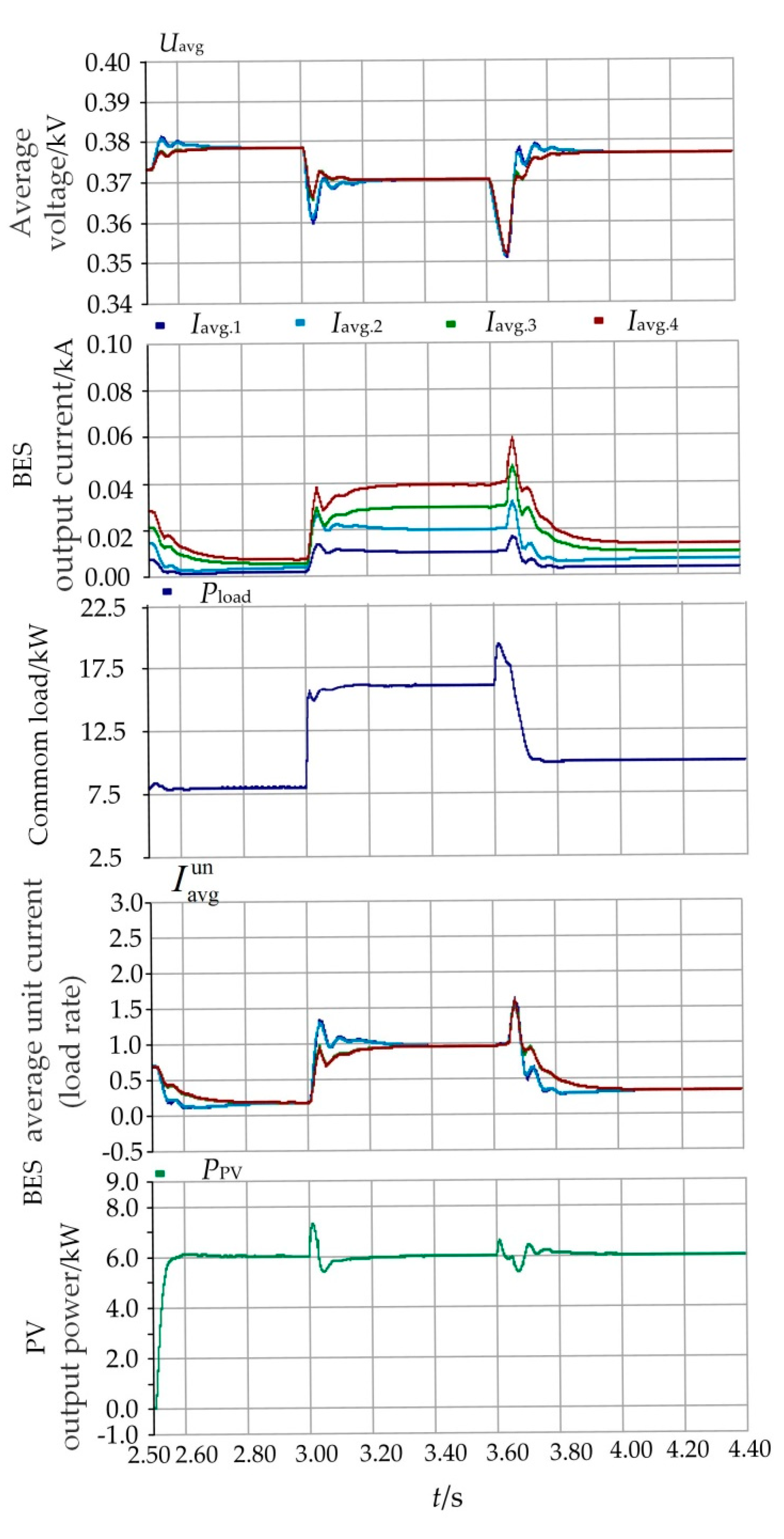
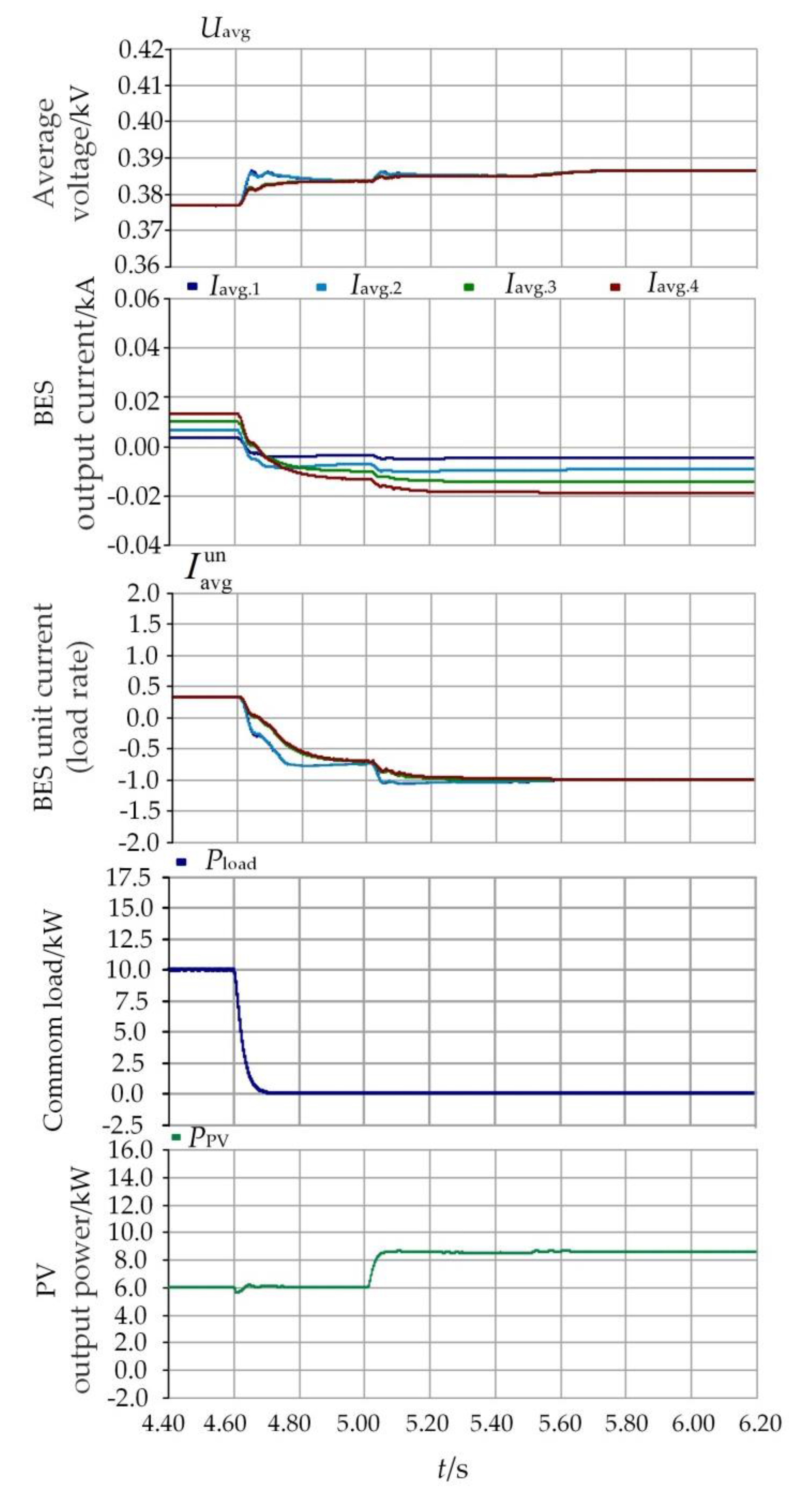
- Mode 2: In case of the power required by the system exceeding BES safe output capacity with excess power, the system power balance is guaranteed by reducing PV output power. At this point, the system power satisfies the following formula:where indicates the maximum safe output power of storage i.
- (3)
- Mode 3: When the bus voltage plummets due to the power vacancy of the system, it is necessary to carry out load-shedding control to guarantee the power supply quality of important loads. At this time, the system power satisfies the following formula:where Pload indicates the residual load after load shedding.
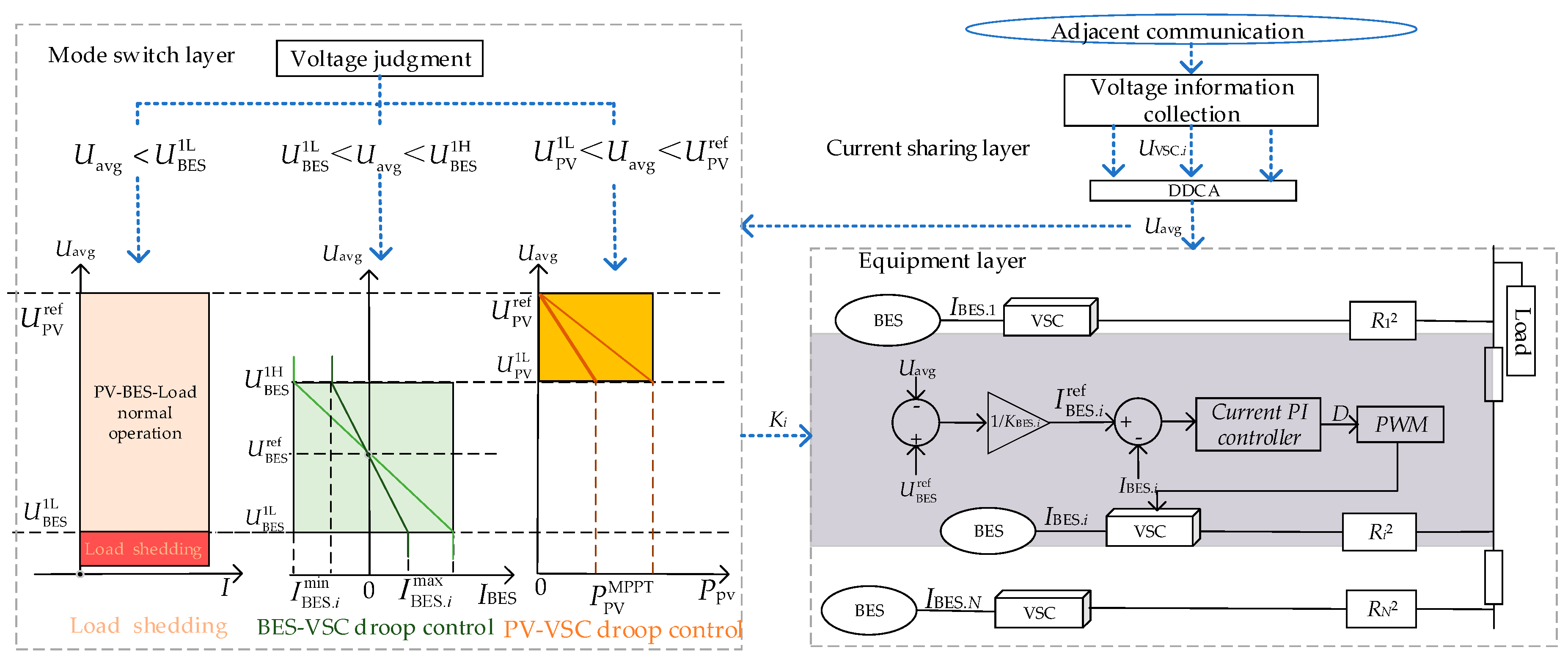
4. Hierarchical, Coordinated Control Strategy Based on Multi-Mode Smooth Switch of an Island DC Microgrid
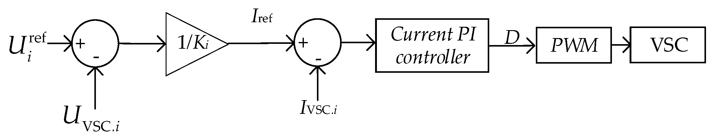
4.1. The First Layer: The Equipment Layer
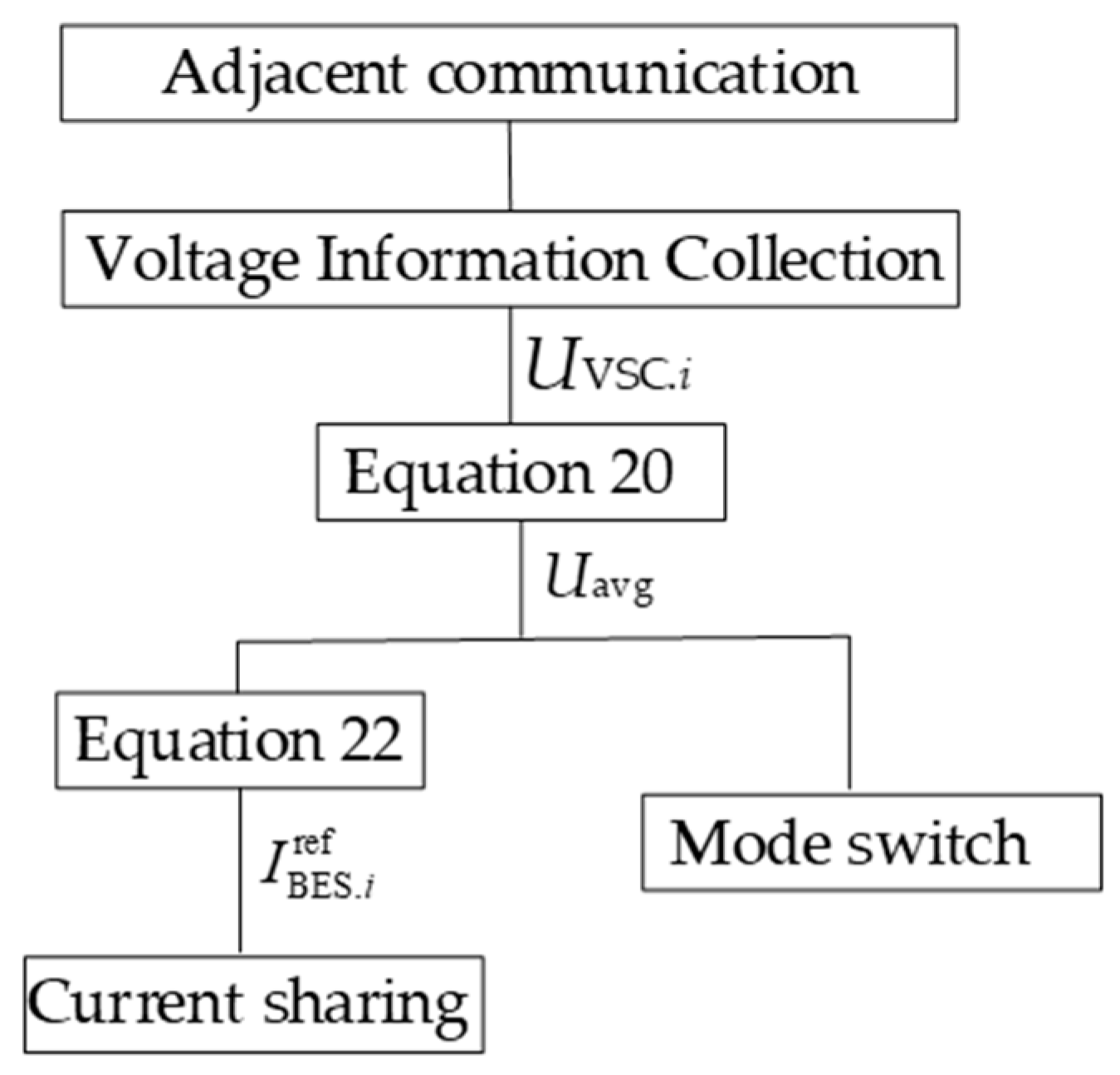
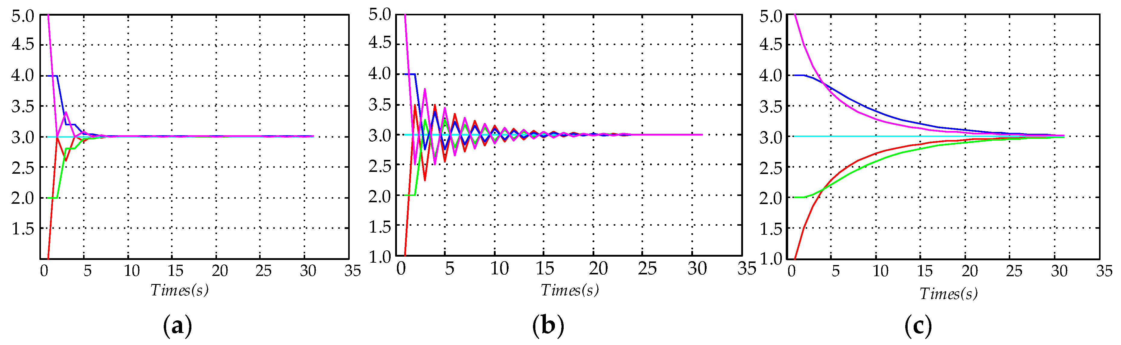
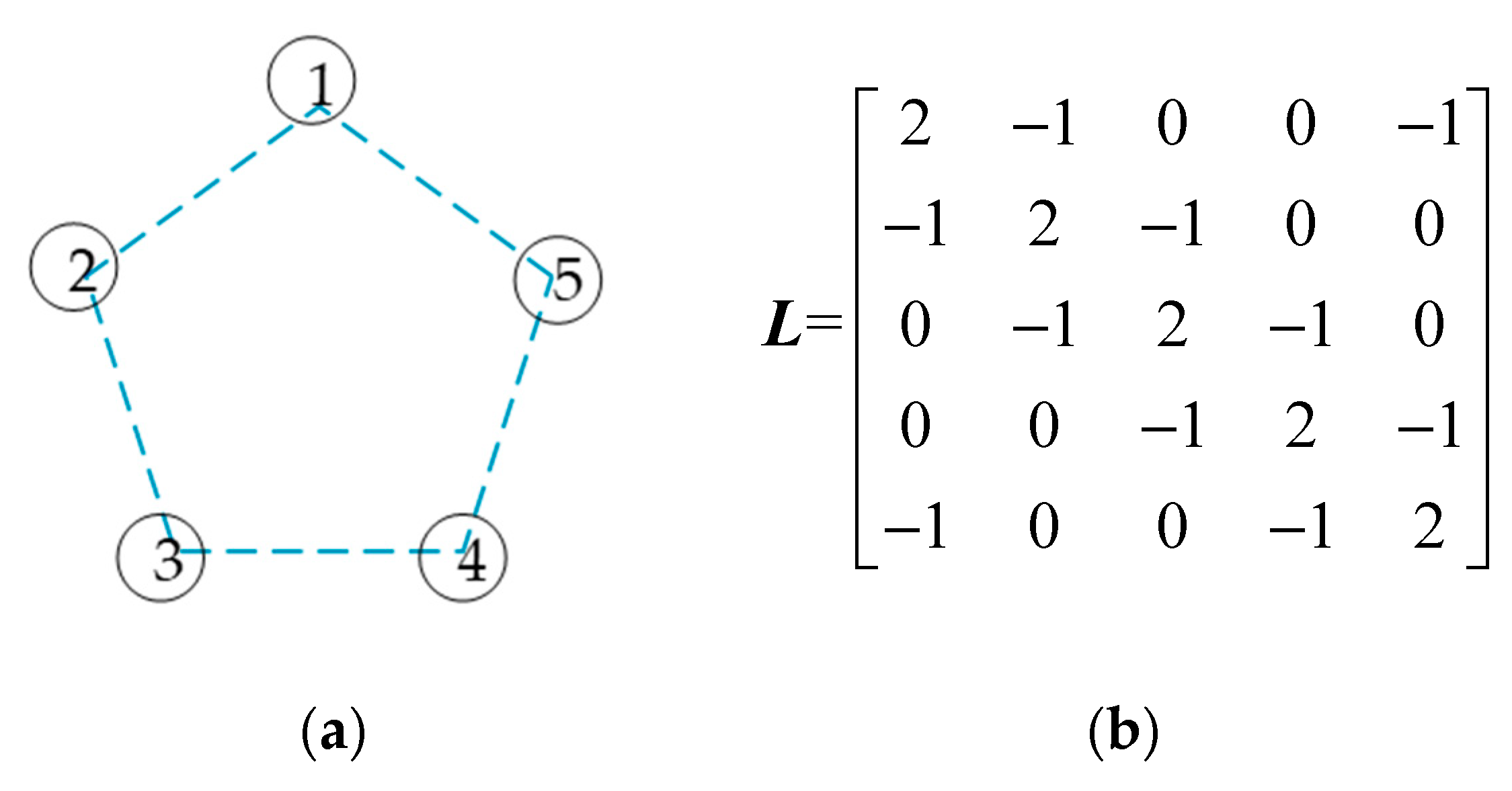
4.2. The Second Layer: The Current-Sharing Layer
4.3. The Third Layer: The Multi-Mode Smooth Switch Layer
5. Example Simulation Analysis
5.1. Situation 1
5.2. Situation 2
5.3. Situation 3
5.4. Situation 4
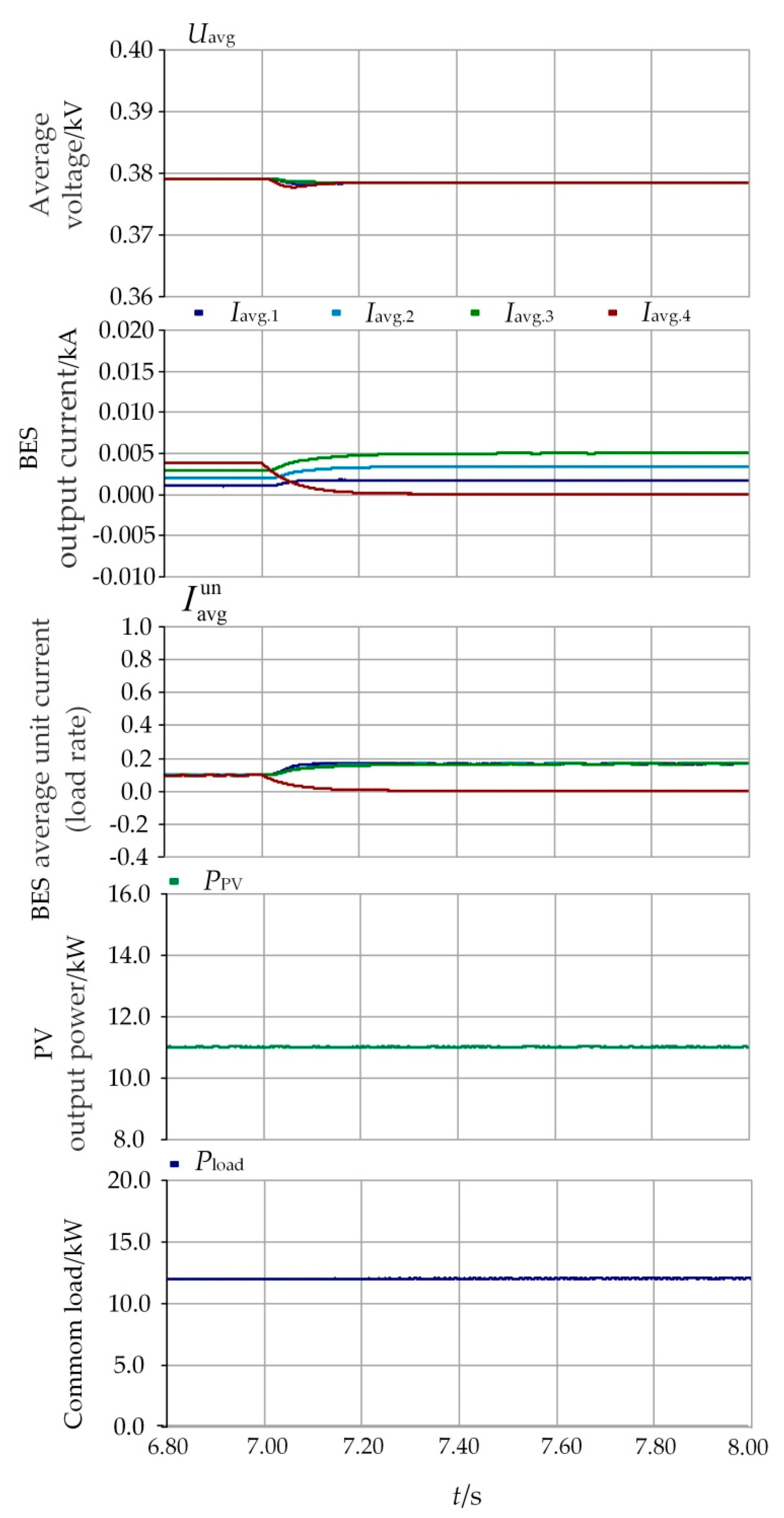
5.5. Situation 5
5.6. Situation 6
6. Conclusions
- (1)
- In the mode switching layer, the control strategy solves the bus voltage deviation problem caused by line resistance and the influence of power loss on a multi-mode switch. Based on virtual bus voltage information, the smooth switch between different operation modes of an island DC microgrid is achieved.
- (2)
- In the current-sharing layer, which avoids centralized control and upper energy management, the control strategy utilizes DDCA to track the output of each VSC unit in real time, eliminating the influence of line resistance and providing reliable virtual bus voltage information for the equipment layer and the mode switching layer.
- (3)
- In the equipment layer, the output current of each unit with current-sharing control achieves accurate load power dispatch. In addition, the control strategies of each unit are regulated in terms of the fluctuation of virtual bus voltage information to achieve system voltage stability.
Author Contributions
Funding
Conflicts of Interest
References
- Arefifar, S.A.; Mohamed, Y.A.R.I. DG Mix, Reactive sources and energy storage units for optimizing microgrid reliability and supply security. IEEE Trans. Smart Grid 2014, 5, 1835–1844. [Google Scholar] [CrossRef]
- Mengelkamp, E.; Gärttner, J.; Rock, K.; Kessler, S.; Orsini, L.; Weinhardt, C. Designing microgrid energy markets: A case study: The brooklyn microgrid. Appl. Energy 2018, 210, 870–880. [Google Scholar] [CrossRef]
- Zhang, J.; Xiong, G.; Meng, K.; Yu, P.; Yao, G.; Dong, Z. An improved probabilistic load flow simulation method considering correlated stochastic variables. Int. J. Electr. Power Energy Syst. 2019, 111, 260–268. [Google Scholar] [CrossRef]
- Loh, P.C.; Li, D.; Chai, Y.K.; Blaabjerg, F. Autonomous operation of hybrid microgrid with AC and DC subgrids. IEEE Trans. Power Electron. 2013, 28, 2214–2223. [Google Scholar] [CrossRef]
- Papadimitriou, C.N.; Zountouridou, E.I.; Hatziargyriou, N.D. Review of hierarchical control in DC microgrids. Electr. Power Syst. Res. 2015, 122, 159–167. [Google Scholar] [CrossRef]
- Lotfi, H.; Khodaei, A. AC Versus DC microgrid planning. IEEE Trans. Smart Grid 2015, 8, 296–304. [Google Scholar] [CrossRef]
- Shuai, Z.; Fang, J.; Ning, F.; Shen, Z.J. Hierarchical structure and bus voltage control of DC microgrid. Renew. Sustain. Energy Rev. 2018, 82, 3670–3682. [Google Scholar] [CrossRef]
- Tucci, M.; Riverso, S.; Vasquez, J.C.; Guerrero, J.M.; Ferrari-Trecate, G. A decentralized scalable approach to voltage control of dc islanded microgrids. IEEE Trans. Control Syst. Technol. 2015, 24, 1965–1979. [Google Scholar] [CrossRef]
- Guo, L.; Feng, Y.; Li, X.; Wang, C. Stability analysis of a DC microgrid with master–slave control structure. In Proceedings of the 2014 IEEE Energy Conversion Congress and Exposition (ECCE), Pittsburgh, PA, USA, 14–18 September 2014; pp. 5682–5689. [Google Scholar]
- Guerrero, J.M.; Vasquez, J.C.; Matas, J.; De Vicuna, L.G.; Castilla, M. Hierarchical Control of Droop-Controlled AC and DC Microgrids—A General Approach toward Standardization. IEEE Trans. Ind. Electron. 2011, 58, 158–172. [Google Scholar] [CrossRef]
- Gu, Y.; Xiang, X.; Li, W.; He, X. Mode-Adaptive Decentralized Control for Renewable DC Microgrid with Enhanced Reliability and Flexibility. IEEE Trans. Power Electron. 2014, 29, 5072–5080. [Google Scholar] [CrossRef]
- Khorsandi, A.; Ashourloo, M.; Mokhtari, H. A Decentralized Control Method for a Low-Voltage DC Microgrid. IEEE Trans. Energy Convers. 2014, 29, 793–801. [Google Scholar] [CrossRef]
- Zhou, T.; Francois, B. Energy management and power control of a hybrid active wind generator for distributed power generation and grid integration. IEEE Trans. Ind. Electron. 2011, 58, 95–104. [Google Scholar] [CrossRef]
- Mi, Y.; Zhang, H.; Fu, Y.; Wang, C.; Loh, P.C.; Wang, P. Intelligent power sharing of dc isolated microgrid based on fuzzy sliding mode droop control. IEEE Trans. Smart Grid 2019, 10, 2396–2406. [Google Scholar] [CrossRef]
- Yazdanian, M.; Mehrizi-Sani, A. Distributed Control Techniques in Microgrids. IEEE Trans. Smart Grid 2014, 5, 2901–2909. [Google Scholar] [CrossRef]
- Eriksson, R.; Beerten, J.; Ghandhari, M.; Belmans, R. Optimizing DC Voltage Droop Settings for AC/DC System Interactions. IEEE Trans. Power Deliv. 2014, 29, 362–369. [Google Scholar] [CrossRef]
- Beerten, J.; Belmans, R. Analysis of Power Sharing and Voltage Deviations in Droop-Controlled DC Grids. IEEE Trans. Power Syst. 2013, 28, 4588–4597. [Google Scholar] [CrossRef]
- Mi, Y.; Wang, Y.; Zhu, Y.; Fu, Y.; Wang, C. Coordinated control for autonomous dc microgrid with dynamic load power sharing. Power Syst. Technol. 2017, 41, 440–447. [Google Scholar]
- Wang, P.; Wang, W.; Meng, N.; Wu, Y. Unified Control Strategy of Islanding and Grid-connected Operations for DC Microgrid. Proc. CSEE 2015, 35, 4388–4396. [Google Scholar]
- Yang, J.; Jin, X.; Wu, X.; Acuna, P.; Aguilera, R.P. Decentralised control method for DC microgrids with improved current sharing accuracy. LET Gener. Transm. Distrib. 2017, 11, 696–706. [Google Scholar] [CrossRef]
- Ziwen, L.; Shihong, M.; Zhihua, F.; Kaiyun, C.; Yilong, K. Accurate Power Allocation and Zero Steady-State Error Voltage Control of the Islanding DC Microgird Based on Adaptive Droop Characteristics. Trans. China Electrotech. Soc. 2019, 34, 795–806. [Google Scholar]
- Wang, H.; Han, M.; Han, R.; Guerrero, J.; Vasquez, J. A Decentralized Current-Sharing Controller Endows Fast Transient Response to Parallel DC-DC Converters. IEEE Trans. Power Electron. 2017, 33, 4362–4372. [Google Scholar] [CrossRef]
- Zhu, S.; Wang, F.; Guo, F.; Wang, Q.; Gao, Y. Overview of Droop Control in DC Microgrid. Proc. CSEE 2018, 38, 72–84. [Google Scholar]
- Gao, Y.; Ai, Q.; Yousif, M.; Muhammad, W. Source-load-storage consistency collaborative optimization control of flexible DC distribution network considering multi-energy complementarity. Int. J. Electr. Power Energy Syst. 2019, 107, 273–281. [Google Scholar] [CrossRef]
- Meng, L.; Dragicevic, T.; Guerrero, J.M.; Vasquez, J.C. Dynamic Consensus Algorithm Based Distributed Global Efficiency Optimization of a Droop Controlled DC Microgrid. In Proceedings of the 2014 IEEE International Energy Conference, Cavtat, Croatia, 13–16 May 2014; IEEE Press: Dubrovnik, Croatia, 2014; pp. 1276–1283. [Google Scholar]
- Oreshkin, B.N.; Coates, M.J.; Rabbat, M.G. Optimization and Analysis of Distributed Averaging with Short Node Memory. IEEE Trans. Signal Process. 2010, 58, 2850–2865. [Google Scholar] [CrossRef]
- Lu, X.; Guerrero, J.M.; Sun, K.; Vasquez, J.C. An Improved Droop Control Method for DC Microgrids Based on Low Bandwidth Communication with DC Bus Voltage Restoration and Enhanced Current Sharing Accuracy. IEEE Trans. Power Electron. 2014, 29, 1800–1812. [Google Scholar] [CrossRef]


| Situation | Operation Mode | Operation Time/s |
|---|---|---|
| 1 | 1 | 0–2.5 s |
| 2 | 1-3-1 | 2.5–4.4 s |
| 3 | 1-2 | 4.4–6.2 s |
| 4 | 2-1 | 6.2–6.8 s |
| 5 | 1 | 6.8–8 s |
| 6 | 1 | 0–2.5 s |
© 2019 by the authors. Licensee MDPI, Basel, Switzerland. This article is an open access article distributed under the terms and conditions of the Creative Commons Attribution (CC BY) license (http://creativecommons.org/licenses/by/4.0/).
Share and Cite
Zhao, Z.; Zhang, J.; He, Y.; Zhang, Y. Island DC Microgrid Hierarchical Coordinated Multi-Mode Control Strategy. Energies 2019, 12, 3012. https://doi.org/10.3390/en12153012
Zhao Z, Zhang J, He Y, Zhang Y. Island DC Microgrid Hierarchical Coordinated Multi-Mode Control Strategy. Energies. 2019; 12(15):3012. https://doi.org/10.3390/en12153012
Chicago/Turabian StyleZhao, Zhongbin, Jing Zhang, Yu He, and Ying Zhang. 2019. "Island DC Microgrid Hierarchical Coordinated Multi-Mode Control Strategy" Energies 12, no. 15: 3012. https://doi.org/10.3390/en12153012
APA StyleZhao, Z., Zhang, J., He, Y., & Zhang, Y. (2019). Island DC Microgrid Hierarchical Coordinated Multi-Mode Control Strategy. Energies, 12(15), 3012. https://doi.org/10.3390/en12153012