Abstract
Torque coordinated control of the relevant power sources has an important impact on the vehicle dynamics and driving performance during the mode transition of the hybrid electric vehicles(HEVs). Considering the dynamic impact problem caused by mode transition, this paper, based upon the structural features of axially paralleled hybrid power system, introduces the bumpless mode switching control theory to analyze multi-mode transition. Firstly, the state transition process is abstracted as the state space transition problem of hybrid system. Secondly, the mode transition is divided into four sub-states, and the state model of each sub-state is established. Thirdly, taking the cost functions as the optimization objective, the state switching process is solved, and the control vectors of each switching process are obtained. Simulation and experimental results show that the proposed control strategy can effectively suppress torque fluctuation, avoid longitudinal acceleration impact, and improve driving performance.
1. Introduction
Faced with the severe situation caused by the dramatic increase in the number of automobiles, new energy vehicles have attracted great attention of the national government with the advantages of energy saving, environmental protection and comfort. Hybrid electric vehicles have taken into account the advantages of electric vehicles and traditional vehicles, so they are favored by domestic and foreign companies and research institutions [1,2,3]. The hybrid power system is generally composed of multiple power sources such as an electric motor and an engine, which are coordinated by clutches or planetary gears to form a variety of working modes. Transition between different working modes often leads to sudden changes in torque, resulting in unstable power output and affecting vehicle driving performance. More and more attention has been paid to how to improve the driving performance during mode transition while ensuring energy saving and emission reduction [4,5,6].
During the mode transition, engine ripple torque, engine-to-motor dynamics differences, model estimation errors, and system parameter uncertainties can cause shock and vibration of the driveline, which will reduce driving comfort and affect the components lives. For the above mode transition control problems, currently, the main solutions can be divided into three categories.
The first type is the torque compensation methods, which mainly track and predict the real-time torque of the engine or the clutch and compensate the engine torque by using the fast response characteristics of the motor torque. Roy I. Davis [7] established an engine torque observer for the hybrid vehicle, calculated the engine torque ripple and used the motor torque to offset the torque ripple of the engine. Hyunsup Kim [8] regarded the torque uncertainty of the engine as an external disturbance and instructed the motor to compensate after the predicted torque was obtained. Wang Lei [9] used fuzzy algorithm to estimate the deviation caused by system parameter uncertainty, and then the sliding mode controller was used to adjust the target torque of the motor. SuYanzhao [10] proposed a dynamic coordinated control strategy, using an active damping feedback compensation method to obtain better results. Wang Chen [11] designed a coordinated control strategy to obtain the engine torque and the motor torque. The simulation and experimental results indicated that the proposed strategy can effectively improve the driving comfort during mode transition. This type of methods requires accurate prediction of engine torque or clutch torque, which needs not only good accuracy and real-time performance of the prediction algorithm, but also high accuracy models of the engine, motor and clutch. However, many existing methods have different degrees of simplification of the engine model or the clutch model, without considering the model parameter uncertainty and nonlinear characteristics, or neglecting the influence of the engine dynamic response characteristics, resulting in great differences from the practical applications [12,13,14].
The second type of method achieves smooth transition by accurately acquiring the torque relationship of each component and coordinating the torque superposition conflict. Hsiu-Ying Hwang and Jia-Shium Chen [15,16] found that applying both the counter-impact torque provided by the motor to suppress the transient torque ripple of the engine and damper bypass clutch with the initial crank angle set to 10 deg can reduce the seat track vibration by more than 70%. He Ren [17] proposed a fuzzy-proportional–integral mixed control strategy to facilitate a smooth transition from electric mode to hybrid driving mode. Although those methods can achieve smooth mode transition to a certain extent, they are not universally applicable and are often limited to a certain kind of specific structures [18,19,20,21].
The third type of method is to introduce advanced control theory or optimization algorithm to solve the vibration and shock problems in the mode transition process [22,23,24,25]. K.V.Vaerenbergh [25] used the reinforcement learning algorithm to control the engagement process of the wet clutch and obtained better simulation results. Chen Li [26] proposed a model reference control (MRC) method to coordinate the motor torque, engine torque, and clutch torque to manage transitions. Wang Shaohua [27] proposed a model predictive control (MPC) method to solve vibration and shock problems during the starting and engaging processes of the engine. Simulation results show that the proposed strategy can effectively suppress the vehicle longitudinal jerk and reduce the clutch wear loss during the mode transition process. Sun Jing [28] used the data-driven predictive control (DDPC) method to reduce the jerk and shorten the switching time. The simulation demonstrated that the DDPC method can achieve better performance compared with the MPC method. In addition to the above research methods, some scholars have applied system theory to study the mode transition process. K. Koprubasi [29] divided the mode into different sub-domains and designed corresponding controllers and discussed the transition control problem of hybrid system. KeremKoprubasi, et al. [30,31] adopt the undisturbed switching control algorithm to realize the simulation analysis from pure electric mode to hybrid drive mode and verified the effectiveness of the control algorithm.
However, all above the studies are equipped with ISG or BSG motors that can start the engine before the mode transition, the coaxial parallel hybrid system studied in this paper is not equipped with a starter motor, and the engine is directly driven by the traction motor. The mode transition control with engine start is relatively complicated, and there is little literature on it. It is difficult to achieve online control of engine transient torque in a shorter clutch engagement process. Therefore, it is necessary to establish a dynamic cooperative control strategy with engine start and study the dynamic process of mode transition comprehensively and systematically.
In this paper, the proposed dynamic torque coordinated control strategy based on undisturbed switching control theory [32,33] is a novel contribution for the HEV dynamic process control during the mode transition process. This method considers the dynamic response characteristics of the mode transition and divides the mode switching into three dynamic processes, which is more accurate than the traditional torque compensation control strategy. In addition, compared with other intelligent control algorithms, this method has simple model, low computational complexity and can be implemented online. This paper focuses on the mode switching process with engine start, and the mode switching process is divided into four state spaces. Each of the state space is represented by the state equation, which is established by mathematically characterizing each state before and after mode transition. Taking the system switching cost function as the optimization object, the switching process in each state is optimized to obtain the control variables. The simulation and experiment results show that the designed torque coordinated control strategy can achieve better mode transition performance compared with the traditional torque compensation control strategy.
The organization of this paper is as follows: Section 2 presents the structure and the powertrain models of the PHEB. Section 3 describes the optimal control strategy. In Section 4 various simulations are provided to validate the control law. In Section 5, the effectiveness of the proposed control strategy is validated by experiments. The concluding remarks are presented in Section 6.
2. Powertrain
Plug-in hybrid electric bus (PHEB) powertrain includes: natural gas engine, clutch, electric motor and automatic mechanical transmission (AMT), as shown in Figure 1. The engine and the motor are coaxially connected by a clutch, which can drive the vehicle separately or together. There are five operating modes for the powertrain: pure electric mode, engine driving mode, hybrid driving mode, driving charging mode, and braking energy recovery mode. These modes switches between each other to meat different power requirements in actual operation. The parameters of the PHEB are shown in Table 1.
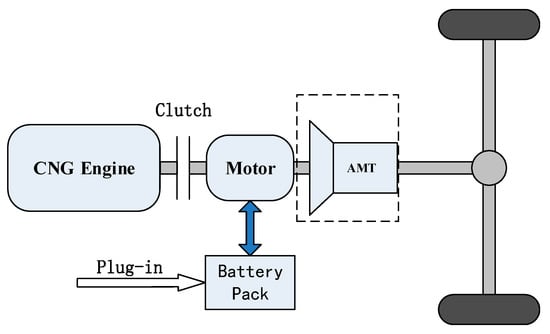
Figure 1.
Configuration of the PHEV powertrain.

Table 1.
Parameters of PHEB.
In the following subsection, considering the difficulty of model parameter acquisition and the requirements of control accuracy, the steady-state model and dynamic correction method are used to model the main power components.
2.1. Engine Model
Since the engine torque is a function of its speed and throttle opening in steady state, the numerical model of the engine can be established by means of the engine test data. The engine fuel consumption characteristics map in Figure 2 is used to obtain the engine torque.
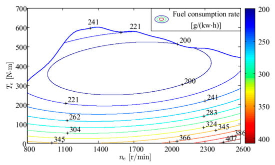
Figure 2.
Engine fuel consumption map.
2.2. Electric Motor Model
The permanent magnet synchronous motor (PMSM) is chosen in this paper. The PMSM model is also established according to the efficiency characteristic data obtained from the experiment. The torque of the electric motor is directly obtained through the motor efficiency map in Figure 3.
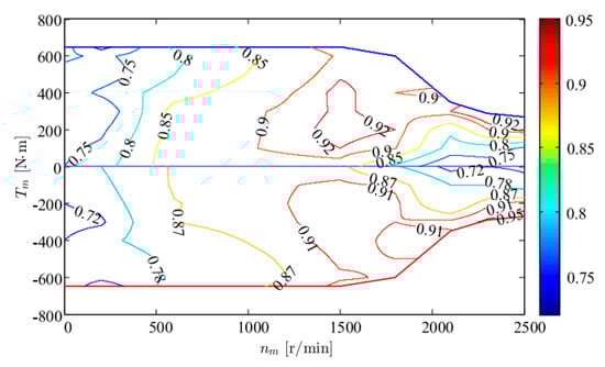
Figure 3.
Motor efficiency map.
2.3. Transmission System Model
The transmission system consists of a clutch, a transmission, a reducer and a half shaft. The clutch model has three states: separation, sliding and combination. In the separation state, the transfer torque is zero; in the combination state, the transfer torque is equal to the motor torque; in the sliding state, the transfer torque is calculated as follows:
where [Appendix A] is the dynamic friction coefficient, [Appendix A] is the effective radius of the clutch friction disk, is the effective area of clutch friction disk, is the clutch press, is the speed difference between main drive and driven plate, is the speed threshold.
The half shaft has an important influence on the shock of the vehicle powertrain. Therefore, the dynamic characteristics of the half shaft are as follows:
where [Appendix A] is the stiffness of the half shaft, is the torsional displacement of the half shaft, [Appendix A] is the equivalent damping coefficient of the half shaft, is the speed difference between the ends of the half shaft.
The transmission can meet the traction demand of the vehicle under different driving conditions by changing the transmission ratio. The reducer transfers the torque from the transmission to the driving wheel, which is similar to the transmission in structure but has a fixed transmission ratio. Therefore, for simplicity, a total gear ratio is used instead of the transmission and reducer. The relationship between the transmission speed ωM and the wheel speed is:
where is the total transmission ratio of the drive system.
2.4. Vehicle Longitudinal Dynamics
The traction acting on the wheel can be written as:
where m is the vehicle mass, g is the gravity acceleration, is the rolling resistance coefficient, is the air density, [Appendix A] is the aerodynamic drag coefficient, [Appendix A] is the bus frontal areas, is the road angle, is the vehicle speed.
3. Method
3.1. Operation Mode
As shown in Table 2, the two power sources of the coaxial parallel hybrid power system can form a variety of working modes through the combination of the clutch. During the mode transition process, the torque and the speed fluctuations of the traction force are often caused by the difference in dynamic response characteristics between the engine and the motor, resulting in longitudinal impact of vehicles. Therefore, it is necessary to coordinate the control of mode transition process to reduce the impact and improve the ride comfort of the vehicle.
Table 2.
System working mode.
Each mode can be considered as a state of the vehicle, and the switching between these states can be seen as a series of discrete events. In each specific mode, the dynamic subsystem of the vehicle can be regarded as a relatively independent continuous variable dynamic system. The control of such hybrid systems can be solved by the bumpless mode switching control shown in Figure 4. In Figure 4, the upper level strategy acts as the system switch and sends out mode switching orders at a certain time according to the control signals (driver’s instructions, speed, power component status, etc.). Different switches correspond to different modes, and each mode is controlled by the bottom level strategy.
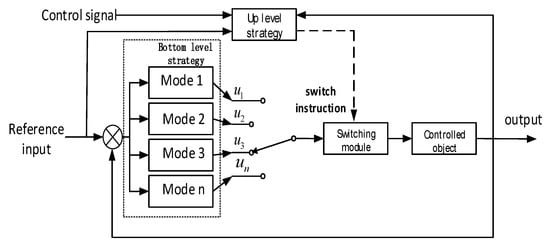
Figure 4.
Bumpless mode switching control structure.
Referring to the basic ideas of undisturbed switching control, this paper focuses on the transition from pure electric mode to hybrid drive mode to make the transition process as smooth as possible to improve the driving performance. Note that the gear position remain unchanged during the mode transition, namely, the influence of the shifting on the drivability is excluded.
3.2. Hybrid System Switching Model
If the hybrid system has m modes and each mode can be described by a series of state equations, it can be expressed as:
where each ∑i represents a mode of the system and is given by the six-tuple:
where is the finite set of state variables. is the finite set of input variables. is the finite set of control variables. is the continuous evolution of the mode i, . is the switching rule corresponding to the mode i to j switch, . is the switching signal of mode i to j, .
Figure 5 briefly describes the dynamic process of mode transition. In mode i, when the switch signal is triggered, the mode i starts to switch to the mode j, and the state space is transformed into the state space by the switching rule . Where is the cost function when mode i switches to mode j to optimize the switching process. Mode transition control seeks a control vector from the control domain to minimize the cost function.
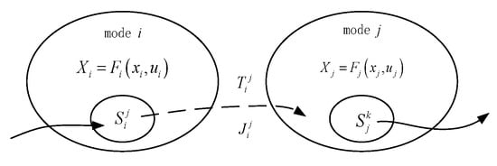
Figure 5.
Hybrid system transition model.
According to the structural characteristics of the coaxial parallel hybrid system, the mode transition is divided into four states: pure electric drive state, clutch sliding state, clutch synchronization state and hybrid drive state. The transition process is shown in Figure 6.
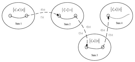
Figure 6.
Mode transition from pure electric to hybrid drive.
The state transition condition is defined as:
where , , [Appendix A] are the threshold speed for in the corresponding condition, respectively. When is lower than , is triggered, the clutch begins to engage; when is lower than , is triggered, the clutch is completely engaged; when is lower than , is triggered, the system enters the hybrid drive mode.
The state variables are chosen as , and the control variables are chosen as . Generally, the clutch is the main executive component of the mode transition, and the clutch was expected to achieve a fast and smooth effect in the transition. Thus, the cost function are:
where , , and [Appendix A] are respectively the weighting factors.
After the transition is characterized by the model and cost function, the smoothness control problem in dynamic process can be simplified to minimize the cost function. Minimizing the cost function will ensure the clutch pull up the engine in the shortest time. Minimizing will ensure that the pre-and post-clutch speeds are fully synchronized. Minimizing can make the downstream driveline torque steady at the end of the engagement.
3.3. Control Design
3.3.1. Pure Electric Drive State
When the vehicle is in pure electric mode, the engine is stopped, the motor drives the vehicle independently, and the clutch is in a disengaged state. In this state, the dynamic characteristics of state variables can be expressed as:
where is the integrated inertia of the PMSM and its fixing mechanism. is the total inertia of the wheels and the equivalent inertia acting on the wheels is the air resistance coefficient, is the rolling resistance, is the equivalent resistance of the motor output shaft.
When state 1 is switched to state 2, the clutch changes from the disengaged state to the partially coupled state, and the engine just acts as a load. Therefore, the motor needs to output additional torque to overcome the frictional resistance torque of the engine in addition to meeting the vehicle torque demand. So, the control variable can be given directly:
where is the vehicle demand torque, is the equivalent damping of engine output shaft.
3.3.2. Clutch Sliding State
The goal of controlling the sliding state of the clutch is to make the engine speed rise to the target starting speed rapidly without inducing undesirable vibrations. At the initiation of clutch engagement, the engine is dragged by the clutch. Since the engine is only used as a load at this phase, it has not been dynamically coupled with the downstream driveline. So, the dynamic characteristics of state variables can be expressed as:
The corresponding state equation is:
where
When the state space is transferred, the performance index matrix can be expressed:
where
According to the Lagrangian optimal solution condition under equality constraints, the control variable can be obtained as follows:
In this state, the engine is in a towed state, so its torque is zero.
3.3.3. Clutch Synchronization State
The goal of controlling the clutch synchronization is that the engine speed can quickly match the motor speed, that is, the clutch driving disc and driven disc speed are quickly consistent and the torque vibration is minimized. In this phase, the engine torque is gradually coupled with the downstream driveline along with the clutch engagement, while the driving motor torque is gradually reduced to ensure a relatively stable power output during the dynamic coupling process. So, the dynamic characteristics of state variables can be expressed as:
The corresponding equation of state is:
where,
When the state space is transferred, the performance index matrix can be expressed:
where,
The optimal control variables u3 can be calculated as follows:
3.3.4. Hybrid Drive State
When the dynamic coupling process is completed, the vehicle enters into the hybrid drive mode. In this state, the dynamic characteristics of state variables can be expressed as follows:
where is the combined inertia of the engine, the motor, the clutch, the PMSM and the input of the ATM.
After entering into the hybrid drive mode, the engine and motor are rigidly connected through the clutch, so the engine speed and the motor speed are the same, and the torque of the engine and the motor meets the torque requirements of the vehicle.
Then, the control variables u4 can be obtained as:
where is the engine torque assigned by the upper energy management strategy.
4. Simulation
The proposed control strategy is simulated in MATLAB/Simulink to verify the effectiveness. The constant torque of the motor is set to be 100 Nm under pure electric mode. When the motor speed reaches 1200 r/min, the transition starts. After the transition, the engine torque is set to be 100 Nm and the motor toque is set to be 150 Nm.
The evaluation indices of the mode transition mainly include riding comfortability and rapidity. Riding comfortability refers to the impact caused by vehicle acceleration in the mode transition. It can be expressed as the change rate of vehicle acceleration, namely, the vehicle jerk. The smaller the jerk, the better the riding comfortability.
where J is the vehicle jerk, a is the vehicle acceleration. According to the criterion of the range of Jerk formulated by Germany, the range of Jerk should be less than 10 m/s3.
Rapidity is described by the mode transition time. The shorter the transition tine, the better the rapidity.
The simulation results are shown in Figure 7. In Figure 7c, the ordinate value D refers to the clutch displacement. It can be seen that the mode transition starts from 3.2 s and ends at 4.15 s with a duration of 0.95 s. The impact mainly occurs in three stages: clutch engagement stage, the engine start stage and engine dynamic coupling stage. Among them, the biggest impact occurs in the clutch initial engagement stage, and the maximum amplitude of the vehicle jerk intensity is 6.96 m/s3 at 3.28 s, when the engine speed and torque are both zero, and the maximum torque of the motor is 240 Nm. The three stages are specifically analyzed as follows:
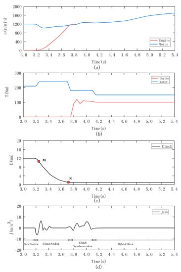
Figure 7.
Simulation results of mode transition with the proposed control strategy. (a) speeds of the engine and motor; (b) torques of the engine and motor; (c) displacement of the clutch (d) jerk of the driveline.
- (1)
- Clutch engagement stageThe clutch engagement stage includes a slipping phase and a synchronous phase. The starting point of the sliding phase is the half-joint point of the clutch, that is, the point where the friction torque is equal to the engine resistance torque. The point M in Figure 7c is the half-joint point. After that, the engine starts to rotate and gradually accelerates, and the engine speed rises with the increase of clutch torque until it reaches the target speed. As shown in Figure 7a, the engine speed reaches 1180 r/min at 3.76 s. At this time, the clutch enters into the synchronous phase, the engine speed and the motor speed are nearly the same, the clutch is locked, and then the motor changes the command torque to reduce the synchronous phase shock, the clutch synchronization is completed. The point N in Figure 7c is the clutch synchronization point.
- (2)
- Engine start stageWhen the engine speed reaches 1200 r/min, the engine executes the start command. As shown in Figure 7b, the start time is from 3.75 s to 3.95 s. During the engine startup, the engine ripple torques are uncertain and can be regarded as torque disturbances. These disturbances caused unexpected vehicle jerks. Although the engine produces an impact during start-up, its impact strength is smaller than the clutch engagement process.
- (3)
- Engine dynamic coupling stageWhen the engine is started, the engine and the motor output the corresponding torque to jointly drive the vehicle according to the upper energy management strategy. Due to the difference of the dynamic characteristics between the engine and the motor, the engine can not respond to the torque in time, so the speed of the engine will fluctuate, thus causing impact. Thanks to the use of torque coordinated control proposed in this paper, the motor torque would compensate for insufficient engine torque, so the impact is small. As shown in Figure 7d, the jerk is 5.12 m/s3.
In order to reflect the advantages of the designed control strategy, two other control methods are introduced for comparison in this paper: traditional torque compensation (TTC) method [17] and model prediction control (MPC) method [28]. The simulation results are shown in Figure 8 and Figure 9. For the traditional torque compensation control method, the mode conversion time starts from 3.2 s to 3.95 s, the transition duration is 0.75 s. The whole mode transition process also goes through three stages. The maximum impact occurs in the sliding stage with the jerk of 14.7 m/s3. For the MPC method, as shown in Figure 9, the mode transition starts at 3.2 s and ends at 4.62 s. The whole mode transition process is mainly affected by two major shocks, which are −6.39 m/s3 at 3.45 s and −5.42 m/s3 at 4.14 s, during the clutch sliding stage and engine start-up stage, respectively. The specific dates are shown in Table 3. As shown in the table, compared with the traditional torque compensation method, the proposed method can achieve smaller jerk, although the mode transition time is a slightly longer. Compared with the MPC method, the proposed method can achieve shorter mode switching time, although the vehicle jerk is a slightly higher. Therefore, the coordinated control method developed in this paper can achieve higher mode transition quality.
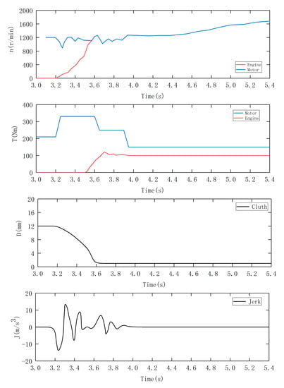
Figure 8.
Simulation results of TTC.
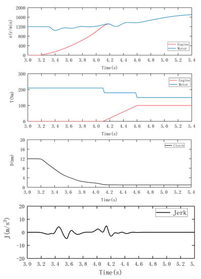
Figure 9.
Simulation results of MPC.
Table 3.
Simulation results comparison.
5. Experimental Verification
In order to verify the control strategy proposed in this paper, a test bench for a coaxial hybrid power system is established. The layout of the test bench is shown in Figure 10a and the bench is shown in Figure 10b. Its main components are: A natural gas engine, a PMSM motor, a clutch and a five speed gearbox, and also there is a dynamometer to generate a resistive torque, to act as a load in order to imitate real vehicle running in a road. The natural gas engine, clutch, electric motor, AMT and dynamometer are connected coaxially, and the battery pack drives the motor through the motor controller.
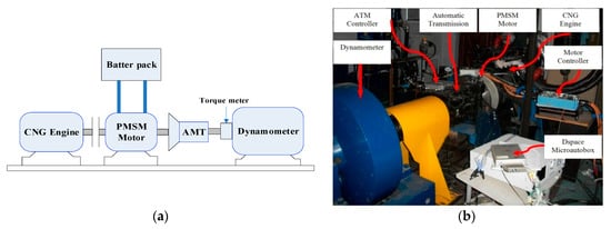
Figure 10.
Layout and physical map of test bench. (a) experimental platform diagram; (b) experimental platform photo.
In order to achieve fast and reliable verification of the control strategy, the experiment uses an advanced rapid control prototype method, which uses dSPACE MicroAutobox instead of the vehicle controller to control the hybrid system. Aiming at the dynamic switching control strategy of hybrid power with engine starting, two groups of experiments are designed in this paper, which are the traditional torque compensation control strategy test and the control strategy test proposed in this paper.
The local working conditions are used to verify the algorithm. During the test, the pure electric mode is switched to the hybrid drive mode. The constant motor torque is 220 N·m under pure electric operation. When the motor speed reaches 1200 r/min, the switching starts. The set torque of the engine after switching is 110 N·m, the motor torque is 160 N·m.
5.1. Motor Torque Compensation Strategy
The experimental results of the motor torque compensation strategy are shown in Figure 11. Specific implementation steps are adopted in reference [34], that is, no control strategy is applied before the clutch is combined, and after the clutch is combined, the output torque of the engine is compensated by the motor. As shown in Figure 11c, the clutch is combined from 17.4 s to 17.8 s, which takes 0.4 s. In the process of clutch combination, the motor drags the motor while driving the vehicle. Due to the time difference between the engine starting resistance torque and the motor compensation torque, the motor speed (Figure 11a) is temporarily pulled down, which is similar to the braking phenomenon. The ride comfort of the vehicle deteriorates instantaneously and has a great impact. Its maximum impact is 16.8 m/s3. Due to the large impact amplitude, the driver and passengers of the vehicle will feel more obvious. It can be seen in Figure 11a that after the clutch is fully combined, the engine speed reaches the starting speed, that is, the engine starts to ignite at 17.8 s. At this time, the engine starting torque will cause vibration of the driveline, and subsequent engine torque co-loading can also cause impact. By 18.4 s, the mode switching completed and the vehicle entered the hybrid drive mode. The entire mode switching time lasts for 1 s.
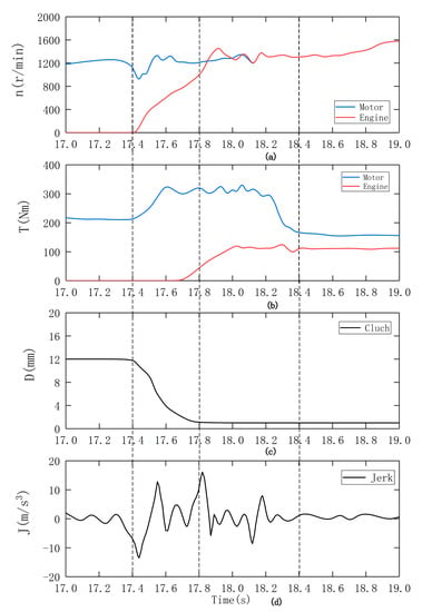
Figure 11.
Results of the traditional method. (a) speeds of the engine and motor; (b) torques of the engine and motor; (c) displacement of the clutch; (d) jerk of the driveline.
It can be seen from the Figure 11d that jerks mainly appear in the clutch-slipping phase and synchronization phase. It is observed that the conventional method rapidly increases the clutch friction torque in the slipping phase. The fast increasing torque acts as a large impulse input to the driveline, thus, impact is excited. Moreover, the friction torque suddenly changes due to the slip-stick transition at the end of the slipping phase, i.e., at the initiation of the synchronization phase. This change produces another large impulse input to the driveline, and the impact continues into the synchronization phase. The result of the experiment illustrates that the traditional torque compensation method is not effective in reducing the impact during the mode transition, and the jerks would be easily noticed by the passengers.
5.2. Dynamic Coordinated Control Strategy
The experimental results of the dynamic coordinated control strategy are shown in Figure 12. As shown in Figure 12a, there is an instantaneous pull-down and pull-up trend of the motor speed during the mode switching, but from the whole mode switching process, the overall amplitude is much lower than that of the conventional motor torque compensation strategy. As shown in Figure 12d, the impact of the switching process is controlled within 10 m/s3, which meets the ride comfort requirements of the vehicle. Similar to the simulation results, the impact mainly occurs in three stages: clutch engagement stage, the engine start stage and engine dynamic coupling stage. Among them, the biggest impact occurs in the clutch initial engagement stage, and the maximum amplitude of the vehicle jerk intensity is −8.9 m/s3 at 17.56 s. The entire mode switching time starts from 17.44 s and ends at 18.64 s, which lasts for 1.2 s.
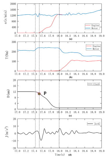
Figure 12.
Results of the proposed method. (a) speeds of the engine and motor; (b) torques of the engine and motor; (c) displacement of the clutch (d) jerk of the driveline.
In the clutch engagement stage, the clutch is combined from 17.45 s and synchronized to 17.92 s. The point P in Figure 12c is the half-joint point, where the clutch friction torque is equal to the engine resistance torque. After that, the engine speed accelerates from 0 to the set starting speed 1200 r/min (Figure 12a). The maximum amplitude of the jerk is −8.9 m/s3 in this stage. In the engine start stage, the start time is from 17.9 s to 18.3 s. When the engine speed reaches 1200 r/min, it starts to ignite. The ripple torque generated during engine ignition causes impact on driveline. The maximum amplitude of the jerk is 5.6m/s3 in this stage, which is smaller than the clutch engagement stage. In the engine dynamic coupling stage, the maximum amplitude of the jerk is 3.8 m/s3, which is the smallest among the three stages. The time of this stage begins at 18.3 s and ends at 18.64 s.
Table 4 is a comparison of the mode conversion time and the maximum jerk produced by the two experimental strategies. From Table 4, it can be seen that the dynamic coordinated control strategy proposed in this paper is much better than the motor torque compensation strategy in terms of maximum jerk. It plays an important role in improving the impact of vehicles, and the jerk is reduced by almost half. For the proposed method, due to precise coordinated control of individual actuator, the impulse input to the driveline is a relative small, causing a slight jerk. Although the duration of mode transition is prolonged, the fluctuation of the driving torque is reduced apparently. Therefore, the mode transition performance for the proposed method is much better than that of the traditional method.
Table 4.
Experiment results comparison.
6. Conclusions
The state switching theory of hybrid system is introduced to solve the dynamic impact problem, which is caused by the intervention of engine torque when the hybrid system is switched from the pure electric mode to the hybrid driving mode. Firstly, the state transition process of hybrid power system is abstracted as the state space transition problem of hybrid system, then the mode transition is divided into four sub-states, and the state model of each sub-state is established. Secondly, taking the cost functions as the optimization objective, the state switching process is solved, and the control vectors of each switching process are obtained. Thirdly, taking the riding comfortability and rapidity as the evaluation indices, the proposed control strategy and other two commonly used control strategies are simulated in the Matlab/Simulink. The simulation results verified the effectiveness of the proposed control strategy. Finally, the advantage of control strategy is further verified by bench test, which can achieve higher mode transition quality.
Since the coaxial parallel hybrid bus powertrain has various working modes, it is found that the impact problem of the transition from the pure electric drive to the hybrid drive is more prominent, and the process is accompanied by state changes of the clutch, the motor and the engine, so only the one-way transition is studied, the reverse transition and other mode transitions are not considered in this paper. Systematically solving the problems of transition will be the main content of the further research.
Author Contributions
This paper is the results of the hard work of all of the authors. Y.Y. and Y.Z. conceived and designed the proposed method. Y.Y.and J.T. conceived and analyzed the data; S.Z. and S.H. contributed to the reviewing of the document, and Y.Y.wrote the paper. All authors gave advice for the manuscript.
Funding
This research received no external funding
Conflicts of Interest
The authors declare no conflict of interest.
Appendix A
Simulation and experiment parameters
Table A1.
Fundamental parameters.
Table A1.
Fundamental parameters.
| 0.01 | 0.7 | ||
| 1.2 kg/m3 | 0.3 | ||
| 0.65 | 0.6 | ||
| 6.73 m2 | 0.4 | ||
| 6200 Nm/rad | 1200 r/min | ||
| 50 Nm/rad | 180 r/min | ||
| 0.25 | 20 r/min | ||
| 0.081m |
References
- Martinez, C.M.; Hu, X.; Cao, D.; Velenis, E.; Gao, B.; Wellers, M. Energy Management in Plug-in Hybrid Electric Vehicles: Recent Progress and a Connected Vehicles Perspective. IEEE Trans. Veh. Technol. 2017, 66, 4534–4549. [Google Scholar] [CrossRef]
- Peng, J.; He, H.; Xiong, R. Rule based energy management strategy for a series–parallel plug-in hybrid electric bus optimized by dynamic programming. Appl. Energy 2017, 185, 1633–1643. [Google Scholar] [CrossRef]
- Yang, Y.; Zhang, Y.; Tian, J.; Zhang, S. Research on a Plug-In Hybrid Electric Bus Energy Management Strategy Considering Drivability. Energies 2018, 11, 2177. [Google Scholar] [CrossRef]
- Zhu, F.; Chen, L.; Yin, C.; Shu, J. Dynamic modelling and systematic control during the mode transition for a multi-mode hybrid electric vehicle. Proc. Inst. Mech. Eng. Part D J. Automob. Eng. 2013, 227, 1007–1023. [Google Scholar] [CrossRef]
- Zeng, X.; Yang, N.; Wang, J.; Song, D.; Zhang, N.; Shang, M.; Liu, J. Predictive-model-based dynamic coordination control strategy for power-split hybrid electric bus. Mech. Syst. Signal Process. 2015, 60, 785–798. [Google Scholar] [CrossRef]
- Tang, X.; Yang, W.; Hu, X.; Zhang, D. A novel simplified model for torsional vibration analysis of a series-parallel hybrid electric vehicle. Mech. Syst. Signal Process. 2017, 85, 329–338. [Google Scholar] [CrossRef]
- Davis, R.I.; Lorenz, R.D. Engine torque ripple cancellation with an integrated starter alternator in a hybrid electric vehicle: Implementation and control. IEEE Trans. Ind. Appl. 2003, 39, 1765–1774. [Google Scholar] [CrossRef]
- Kim, H.; Kim, J.; Lee, H. Mode transition control using disturbance compensation for a parallel hybrid electric vehicle. Proc. Inst. Mech. Eng. Part D J. Automob. Eng. 2011, 225, 150–166. [Google Scholar] [CrossRef]
- Wang, L.; Zhang, Y.; Shu, J.; Yin, C. Coordinated control of a series-parallel hybrid electric bus during EV/HEV mode transition. WSEAS Trans. Circuits Syst. 2012, 11, 198–209. [Google Scholar]
- Su, Y.; Su, L.; Hu, M.; Qin, D.; Zhang, T.; Fu, C. Dynamic coordinated control during mode transition process for a compound power-split hybrid electric vehicle. Mech. Syst. Signal Process. 2018, 107, 221–240. [Google Scholar] [CrossRef]
- Wang, C.; Zhao, Z.; Zhang, T.; Li, M. Mode transition coordinated control for a compound power-split hybrid car. Mech. Syst. Signal Process. 2017, 87, 192–205. [Google Scholar] [CrossRef]
- Oh, J.; Choi, S.B.; Chang, Y.J.; Eo, J.S. Engine clutch torque estimation for parallel-type hybrid electric vehicles. Int. J. Automot. Technol. 2017, 18, 125–135. [Google Scholar] [CrossRef]
- Tarasow, A.; Wachsmuth, G.; Lemieux, J.; Serway, R.; Bohn, C. Online estimation of time-varying torque characteristics of automotive clutches using a control oriented model. In Proceedings of the 2013 American Control Conference, Washington, DC, USA 17–19 June 2013; IEEE: Piscataway, NJ, USA, 2013; pp. 6752–6757. [Google Scholar]
- Zhao, Z.; He, L.; Yang, Y.; Wu, C.; Li, X.; Karl Hedrick, J. Estimation of torque transmitted by clutch during shifting process for dry dual clutch transmission. Mech. Syst. Signal Process. 2016, 75, 413–433. [Google Scholar] [CrossRef]
- Hwang, H.-Y. Minimizing Seat Track Vibration That is Caused by the Automatic Start/Stop of an Engine in a Power-Split Hybrid Electric Vehicle. J. Vib. Acoust. 2013, 135, 061007. [Google Scholar] [CrossRef]
- Chen, J.-S.; Hwang, H.-Y. Engine automatic start-stop dynamic analysis and vibration reduction for a two-mode hybrid vehicle. Proc. Inst. Mech. Eng. Part D J. Automob. Eng. 2013, 227, 1303–1312. [Google Scholar] [CrossRef]
- He, R.; Tian, X.; Ni, Y.; Xu, Y. Mode transition coordination control for parallel hybrid electric vehicle based on switched system. Adv. Mech. Eng. 2017, 9, 1–12. [Google Scholar] [CrossRef]
- Van Berkel, K.; Hofman, T.; Serrarens, A.; Steinbuch, M. Fast and smooth clutch engagement control for dual-clutch transmissions. Control Eng. Pract. 2014, 22, 57–68. [Google Scholar] [CrossRef]
- Han, K.; Yoon, Y. Clutch Transmissible Torque Estimation for Dry Dual Clutch Transmission Control; Springer: Berlin/Heidelberg, Germany, 2013; pp. 449–456. [Google Scholar]
- Kim, G.-W. Systematic gear shift model for an automatic-transmission-based parallel hybrid electric vehicle. Proc. Inst. Mech. Eng. Part D J. Automob. Eng. 2012, 226, 895–904. [Google Scholar] [CrossRef]
- Yu, C.-H.; Tseng, C.-Y.; Wang, C.-P. Smooth gear-change control for EV Clutchless Automatic Manual Transmission. In Proceedings of the 2012 IEEE/ASME International Conference on Advanced Intelligent Mechatronics (AIM), Kaohsiung, Taiwan, 11–14 July 2012; IEEE: Piscataway, NJ, USA, 2012; pp. 971–976. [Google Scholar]
- Glielmo, L.; Vasca, F. Engagement control for automotive dry clutch. In Proceedings of the American Control Conference, Chicago, IL, USA, 28–30 June 2000; IEEE: New York, NY, USA, 2000; pp. 1016–1017. [Google Scholar]
- Dutta, A.; Zhong, Y.; Depraetere, B.; Van Vaerenbergh, K.; Ionescu, C.; Wyns, B.; Pinte, G.; Nowe, A.; Swevers, J.; De Keyser, R. Model-based and model-free learning strategies for wet clutch control. Mechatronics 2014, 24, 1008–1020. [Google Scholar] [CrossRef]
- Minh, V.T.; Rashid, A.A. Automatic control of clutches and simulations for parallel hybrid vehicles. Int. J. Automot. Technol. 2012, 13, 645–651. [Google Scholar] [CrossRef]
- Van Vaerenbergh, K.; Rodriguez, A.; Gagliolo, M.; Vrancx, P.; Nowe, A.; Stoev, J.; Goossens, S.; Pinte, G.; Symens, W. Improving wet clutch engagement with reinforcement learning. In Proceedings of the 2012 International Joint Conference on Neural Networks (IJCNN), Brisbane, Australia, 10–15 June 2012; IEEE: Piscataway, NJ, USA, 2012; pp. 1–8. [Google Scholar]
- Chen, L.; Xi, G.; Sun, J. Torque Coordination Control During Mode Transition for a Series-Parallel Hybrid Electric Vehicle. IEEE Trans. Veh. Technol. 2012, 61, 2936–2949. [Google Scholar] [CrossRef]
- Wang, S.; Xia, B.; He, C.; Zhang, S.; Shi, D. Mode transition control for single-shaft parallel hybrid electric vehicle using model predictive control approach. Adv. Mech. Eng. 2018, 10, 1–10. [Google Scholar] [CrossRef]
- Sun, J.; Xing, G.; Zhang, C. Data-Driven Predictive Torque Coordination Control during Mode Transition Process of Hybrid Electric Vehicles. Energies 2017, 10, 441. [Google Scholar] [CrossRef]
- Koprubasi, K.; Westervelt, E.R.; Rizzoni, G. Toward the systematic design of controllers for smooth hybrid electric vehicle mode changes. In Proceedings of the American Control Conference, New York, NY, USA, 11–13 July 2007; IEEE: New York, NY, USA, 2007; pp. 2725–2730. [Google Scholar]
- Koprubasi, K. Modeling and Control of a Hybrid Electric Vehicle for Drivability and Fuel Economy Improvements. Ph.D. Thesis, The Ohio State University, Columbus, OH, USA, 2008. [Google Scholar]
- Zhao, Z.; He, N.; Zhu, Y.; Yu, Z. Mode transition control for four wheel drive hybrid electric car. J. Mech. Eng. 2011, 47, 100–109. [Google Scholar] [CrossRef]
- Zaccarian, L.; Teel, A.R. A common framework for anti-windup, bumpless transfer and reliable designs. Automatica 2002, 38, 1735–1744. [Google Scholar] [CrossRef]
- Malloci, I.; Hetel, L.; Daafouz, J.; Iung, C.; Szczepanski, P. Bumpless transfer for switched linear systems. Automatica 2012, 48, 1440–1446. [Google Scholar] [CrossRef]
- Ni, C.; Zhang, Y.; Zhao, Q.; Adel, B. Dynamic Torque Control Strategy of Engine Clutch in Hybrid Electric Vehicle. J. Mech. Eng. 2013, 49, 114–121. [Google Scholar] [CrossRef]
© 2019 by the authors. Licensee MDPI, Basel, Switzerland. This article is an open access article distributed under the terms and conditions of the Creative Commons Attribution (CC BY) license (http://creativecommons.org/licenses/by/4.0/).