Article

Oil-Cooling Method of the Permanent Magnet Synchronous Motor for Electric Vehicle

National Engineering Laboratory for Electric Vehicles, Beijing Institute of Technology, No. 5 South Zhongguancun Street, Haidian District, Beijing 100081, China
*
Author to whom correspondence should be addressed.
Energies 2019, 12(15), 2984; https://doi.org/10.3390/en12152984
Submission received: 21 June 2019 / Revised: 25 July 2019 / Accepted: 28 July 2019 / Published: 2 August 2019

Abstract

:
The typical motor has poor heat dissipation conditions that are limited by the installation space and working environment, and the high operation temperature increase has been a bottleneck to improve the power density and torque density. The inner rotor motor is considered to be the research object, and an oil-cooling structure for end winding and stator core is proposed. The heat inside the motor is mainly carried away through the lubricating oil in the form of heat conduction and convection heat transfer. The 3d motor model was built using the ANSYS software. The temperature field of the motor was simulated to analyze the temperature distribution inside the motor under rated and peak working conditions. The low-speed high-torque test and one-hour temperature-rise test of the motor prototype were performed on a bench built in the laboratory. The comparison between the test results with water-cooled motor shows that the temperature-rise rate of oil-cooled motor with the same electromagnetic structure is slower than that of water-jacketed cooled motor, and the temperature difference between the front and back of the motor decreases by 18 °C in half an hour. The oil-cooled method has a good cooling effect on the stator core and works for longer time under rated conditions.

1. Introduction

A hub motor must have high-torque density which can effectively reduce the vehicle under sprung mass. It should have a large efficient working range to reduce the motor loss in the process of driving. There are two ways to improve the torque density of hub motors: one is to increase the effective air gap area in the same volume, the second is to increase electrical load and magnetic load within the linear range. It is necessary to explore the electromagnetic structure of the new hub motor to increase the effective air gap area of the motor. In order to improve the electrical load and magnetic load in the linear range as far as possible, it is necessary to design a reasonable cooling structure [1,2].
In the traditional oil-cooling method, the stator and rotor of the motor are immersed in the cooling oil, and the cooling effect is good. However, the cooling oil must pass through the blade agitation, which results in a large energy loss at high speed. With the research of the oil-cooling mode, there are increasingly many new oil-cooled structures in the motor. Li Ye separated the stator and rotor of the motor with the ultra-thin casing made of glass fiber, and directly cooled the end winding by the cooling oil in the sleeve, which reduced the average temperature of the motor by 40% [3,4,5,6,7]. Camilleric presented a thermal fluid flow model to directly predict the temperature and flow distribution of the oil-cooled motor, establish the numerical model to predict the motor section stator temperature distribution, identify hotspots and its location, and cause the hot spot temperature to reduce by 13 °C by improving the motor stator flow geometry. The error was within 6% compared with the experimental results through measuring the 1/4 model of the stator [8,9,10,11,12,13]. Lindh used the double stator permanent magnet synchronous motor with 100 kW as the research object, and set up stainless-steel coolant pipes for cooling. That research found that the direct cooling reduced the temperature by approximately 50 °C compared with the indirect cooling method.
Motor losses are mainly concentrated in the windings and core, so it is necessary to design the cooling structure to make the oil as close as possible to the heat source to improve the cooling effect [14,15,16,17,18,19,20]. The above cooling forms are mainly only cooling for the end winding or stator core. They are not simultaneously cooling multiple heat sources from inside the motor. Therefore, the cooling structure is designed by passing the oil through the end oil cover and stator core holes, which is mainly aimed at the end winding and stator core to improve the cooling effect, and the hub motor power density and torque density.

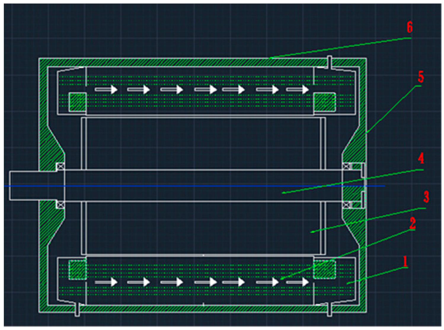
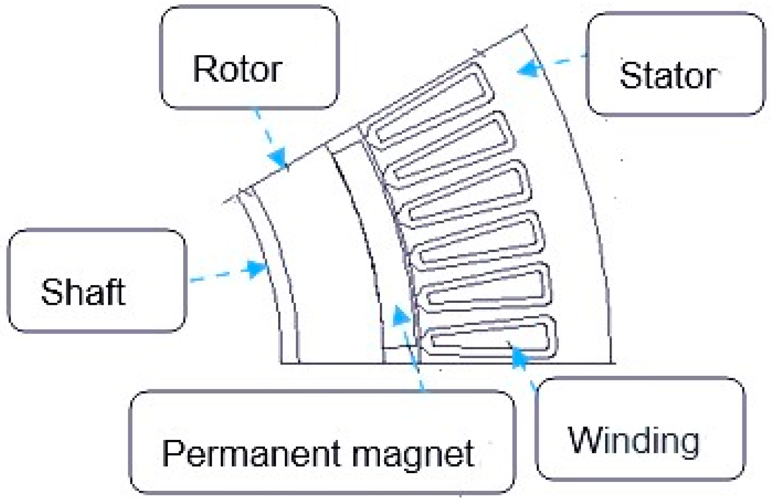
2. Oil-Cooled Structure Model of Hub Motor

In order to improve the torque density of hub motor, the design scheme of fractional slot concentrated winding is adopted. The application process of the high-power density motor has the characteristics of small volume, light quality and high reliability; however, the improvement of power density means the motor loss density increases and the speeding up of the temperature rise, which will accelerate the internal insulation aging and reduce the reliability of the motor. Therefore, a reasonable cooling system is needed to cool the motor and ensure its normal operation [21,22,23,24].
The oil-cooling structure is best to achieve the following characteristics:
  • It can ensure the safe and stable operation of the motor within the range of temperature rise and the operating environment;
  • Fluid surface heat transfer coefficient is large enough, and heat exchange is sufficient, and efficient;
  • The resistance coefficient of lubricating oil is small along the pipeline;
  • The original structural elements of the motor should be kept as much as possible, especially the heat transfer path should be kept unchanged;
  • Oil road section shape should be uniform, the number of elbows should be small, the local resistance of elbows should be as small as possible;
  • Easy to use and maintain.
The motor is composed of shell, front end cover, back end cover, rotor, stator and shaft. Leading and rear oil guide covers are designed at both ends of the stator. The end winding is immersed in oil for cooling. A single oil outlet is arranged above the shell, and a double oil inlet is arranged below the shell. There is an axial oil channel at the yoke of the stator, as shown in the white arrow in Figure 1, which can connect the oil in the front and rear oil cover packages and cool the stator core at the same time. Heat inside the motor is mainly carried away by lubricating oil in the form of conduction and convection, and the oil is cooled by water through heat exchange. This oil-cooling method can not only effectively cool the end winding, but also cool the silicon steel sheet of the motor, which can greatly reduce the motor internal temperature rise and improve the power density of the motor. Motor parameters are shown in Table 1.

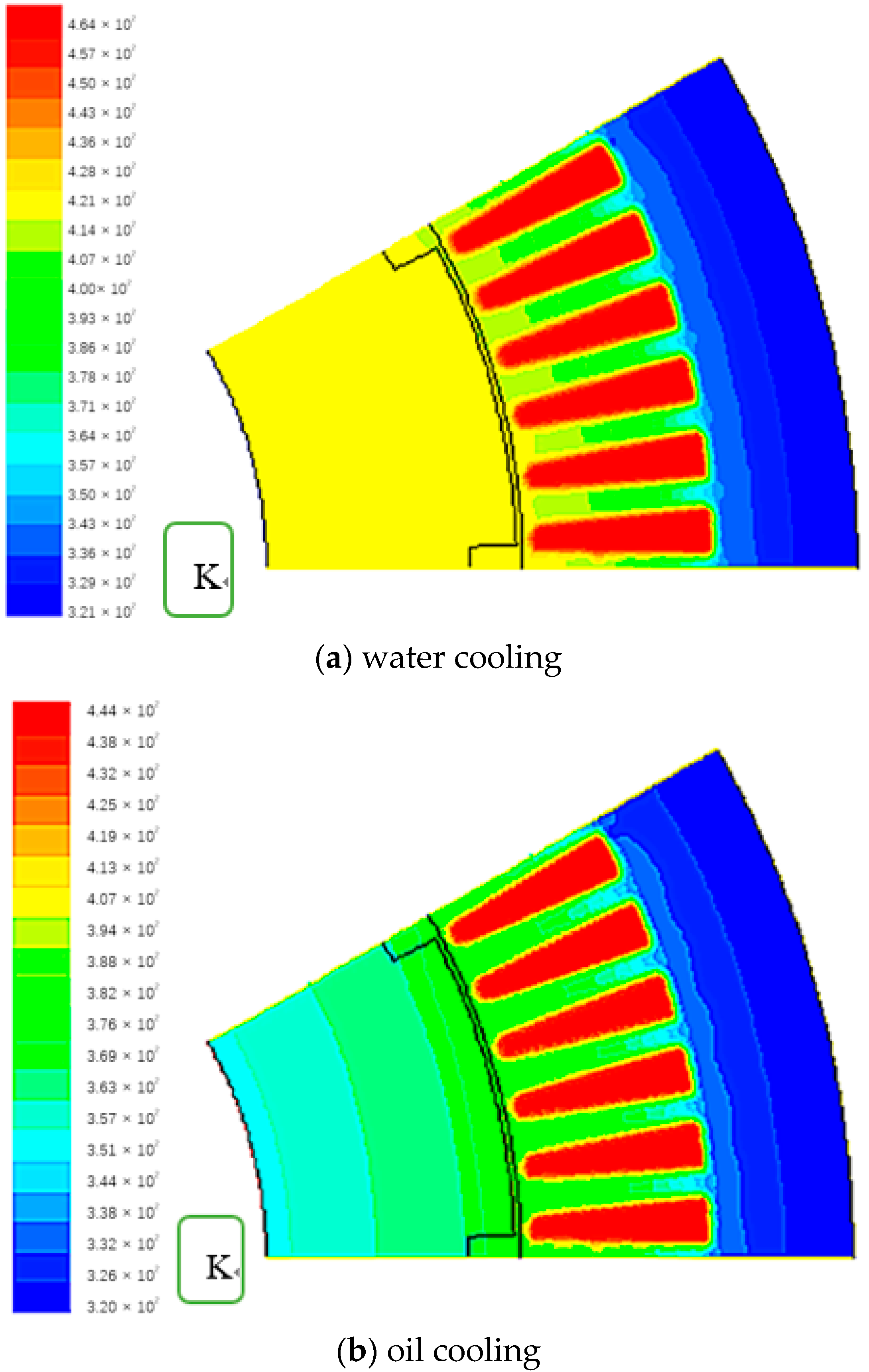
3. Temperature Field Simulation

At present, the most commonly used numerical methods of temperature field are the equivalent thermal network method and the finite element method. The finite element method has good boundary adaptability and high precision, but it takes a long time to solve. In this section, ANSYS simulation software is used to study and analyze the temperature distribution inside the motor under rated working conditions and peak torque working conditions. The motor structure is shown in Figure 2 and the cooling structure is shown in Figure 1.
The finite element method is a highly efficient and commonly used numerical method. Discrete the continuous solution domain into a group of elements, and use the approximation function assumed in each element to solve the unknown field function to be solved in the domain. The approximate function is usually expressed by the unknown field function and the numerical interpolation function of its derivative at each node of the element. Therefore, a continuous infinite degree of freedom problem becomes a discrete finite degree of freedom problem. ANSYS has powerful pre-modeling and post-data processing modules. It can automatically divide the grid in a visual and quick way and generate the data for finite element analysis. The calculated results are arranged into deformation map and equivalent distribution map according to requirements, which is convenient for extremum search and list transmission of required data [25,26,27,28].
First, the following assumptions are made before establishing the motor simulation model [29,30]:
(1)
due to the superposition of the axial silicon steel sheet of the motor, the thermal conductivity is small, so the axial thermal conductivity of the motor is ignored;
(2)
do not consider the heat dissipation of the end winding of the motor;
(3)
the assembly clearance between the outer surface of the stator and the housing and the clearance between the inner surface of the rotor and the shaft are ignored.
Based on the above assumptions, the complex three-dimensional model inside the motor is simplified into a two-dimensional model for temperature field analysis. In order to ensure the calculation speed of the model, the 1/12 model of the motor is selected for analysis considering the symmetry of the motor, and the model is established as shown in Figure 3 The mesh generation diagram is shown in Figure 4 Create quadrilateral structural mesh for shaft and stator planes, mesh size is 5. Rotor and permanent magnet planes are also quadrilateral structural mesh, and mesh size is 3. Create triangular grid for winding wedge-shaped regions, and radiate outward along the wedge-shaped regions, quadrilateral structural mesh is used. Mesh size is 1.
There are three kinds of losses in motor operation: stator winding copper loss, core loss and mechanical loss. This motor mainly studies winding copper loss and core loss.
Combined with temperature correction and frequency correction, the AC/DC resistance ratio ( R a c / R d c ) of the motor at different operating frequencies and temperatures can be corrected, so that Equation (1) can be used to quickly calculate the copper loss of the motor within the whole operating range.
P a c = I 2 R d c ( ( R a c / R d c ) 1 ) + I 2 R d c
The improved formula based on Bertotti trinomial model is adopted. The hysteresis loss, eddy current loss and additional loss of stator core are:
{ P h = k = 1 N K h k f ( B k max α + B k min α ) P e = K e k = 1 N K e k 2 f 2 ( B k max 2 + B k min 2 ) P e x c = K e x c 1 T 0 T | | d B r ( t ) d t | 2 + | d B t ( t ) d t | 2 | 2 d t
Br and Bt are radial and tangential flux densities in the core.
According to the above parameters, set the corresponding material properties and boundary conditions in the motor model. Set the temperature of water and oil to 25 °C.

3.1. Analysis of Rated Operating Conditions Simulation Results

Figure 5a is the simulation result of water jacket cooling under rated working conditions, and Figure 5b is the simulation result of oil cooling at the same conditions. By comparing the temperature distributions of the two cooling modes, we can see that the highest temperature occurs in the windings, and the temperature rises of the stator windings under the two cooling methods are relatively high. The temperature of the stator yoke is lower than that of water cooling, which indicates that the axial oil cooling of the stator has a good cooling effect on the iron core. Most of the heat of rotor and permanent magnet is taken away by oil liquid. The temperature of rotor and permanent magnet drops to 100 °C, which is about 15% lower than only water cooling. It can effectively reduce the influence of temperature rise on permanent magnet. The temperature of permanent magnet decreases from 127 °C to 102 °C, which can reduce the possibility of permanent magnet demagnetization and improve the ability of motor to adapt to high temperature working environment.

3.2. Analysis of Peak Operating Conditions Simulation Results

Figure 6 shows the simulation results of oil cooling and water cooling under peak conditions, and (a) shows the temperature variation under water cooling, (b) is the temperature variation diagram of oil-cooling mode. Winding and rotor temperature change under peak condition trend the same measurement with the rated conditions, stator and permanent magnet temperature obviously drops with oil cooling, but because the winding temperature rises to 160 °C, so the motor cannot work for a long time under peak conditions.

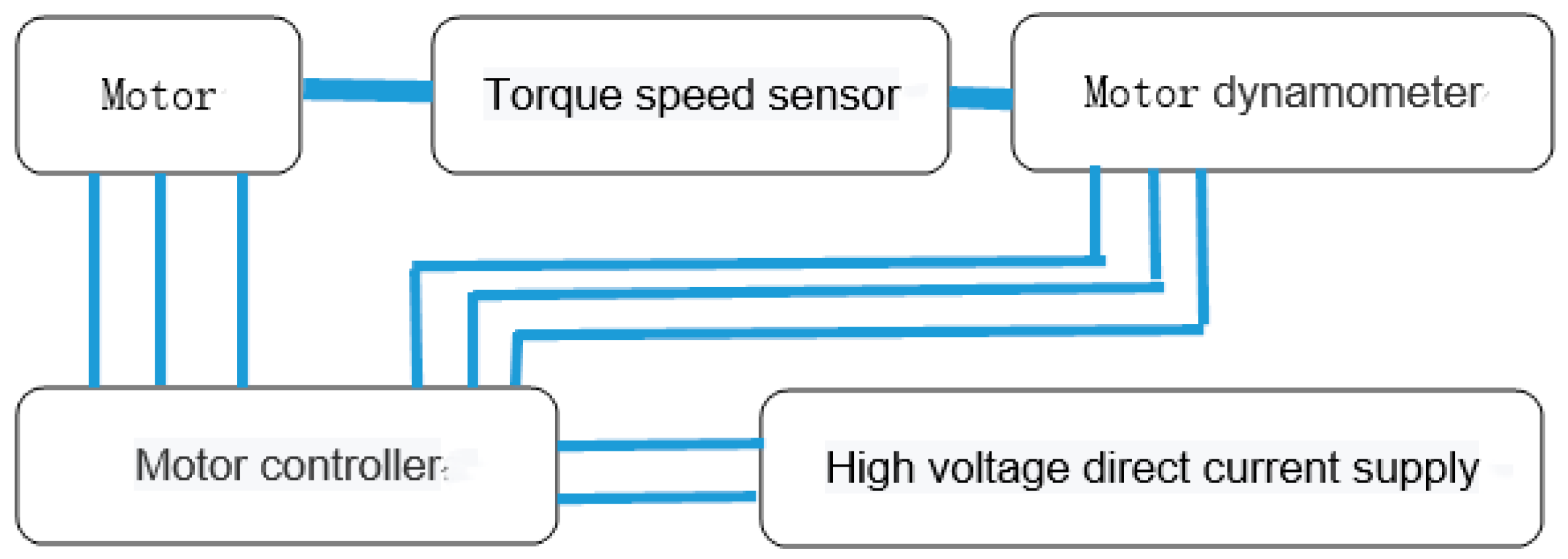
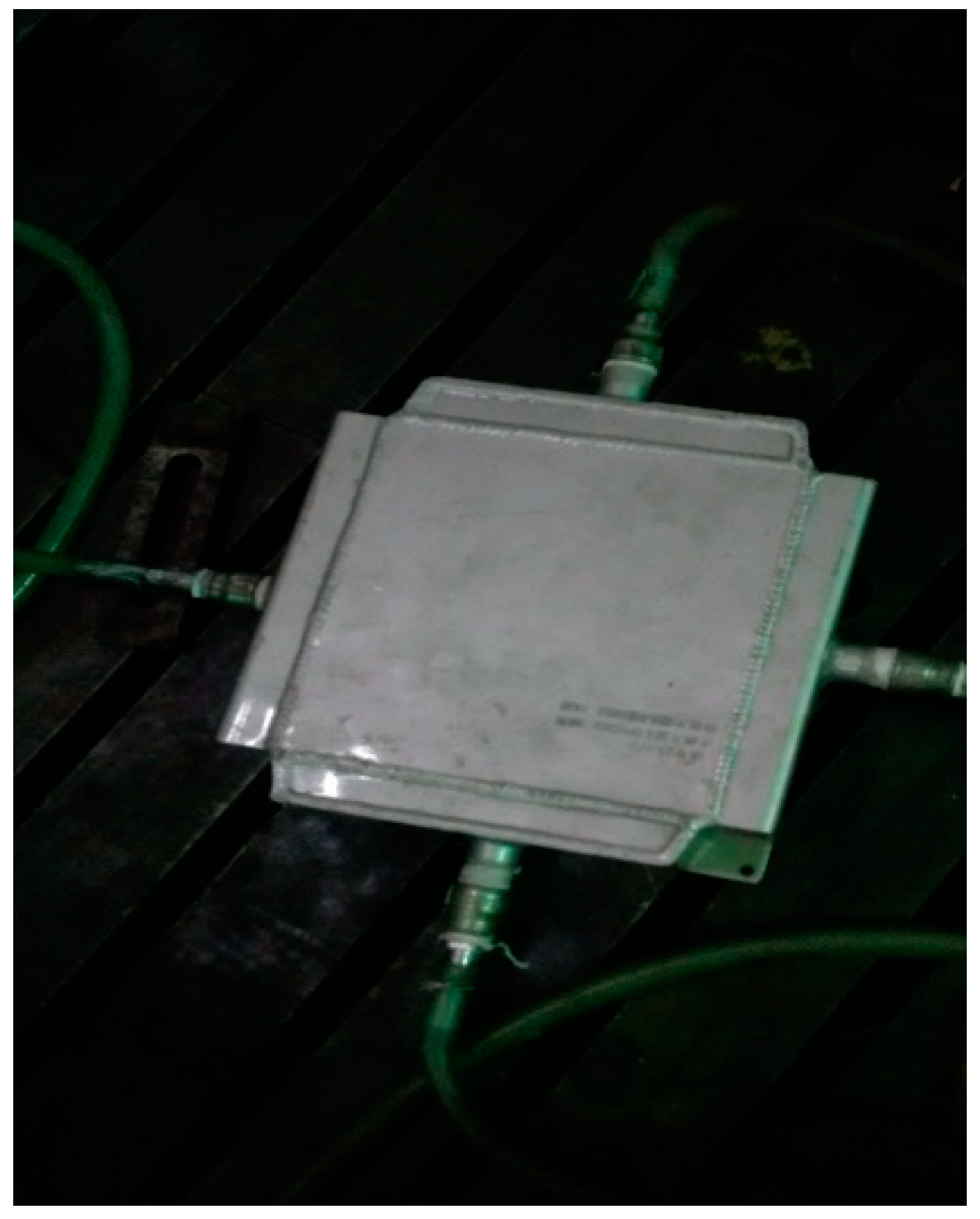
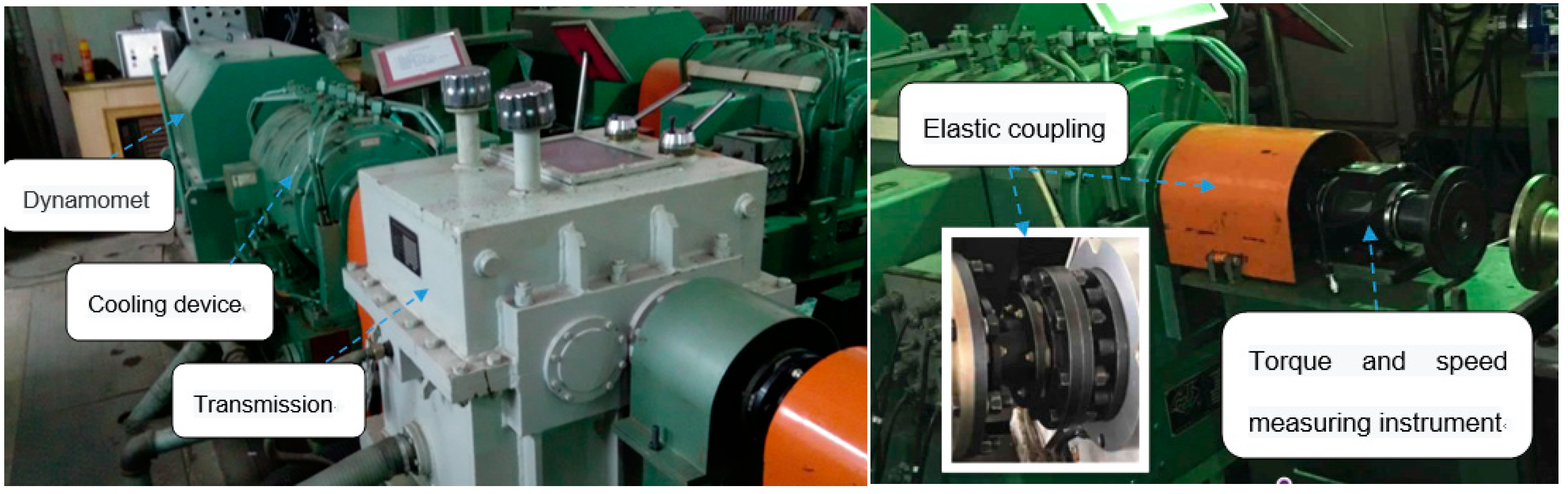
4. Motor Test Analysis

The test principle of the prototype of the motor is shown in Figure 7. A 900-voltage DC power supply was used to supply the power. The torque and rotation speed of the motor were tested by the torque and rotation speed measuring instrument. The dynamometer was used as the loading device. It was necessary to test the running state, performance, vibration and temperature rise of the motor under different working conditions.
The oil-cooled motor test bench with rated power of 90 kW is shown in Figure 8. There is an oil discharging port at the end of the motor. The oil outlet is at the top of the motor, and the temperature sensor of outlet oil is attached to the oil outlet wall. A temperature sensor is embedded in the motor to test the temperature of the end winding. The performance of the motor was evaluated by one-hour temperature-rise test of rated power and low-speed high-torque test. Zero drift values have been subtracted from the current values in the data.
Figure 9 shows the oil-water heat exchanger to cool the oil flowing from the outlet pipe. Figure 10 shows the oil barrel. The submersible oil pump is fixed in the oil barrel. The oil inlet temperature sensor is on the side of the oil pump. No. 32 Great Wall lubricating oil is used in the research, which can meet the insulation requirements. The flow rate of the oil pump is 18 L/min.
Figure 11 shows the electric-driven test bench, and the dynamometer was used as the loading device. Torque, rotation speed, power, voltage, current and other parameters were set by the numerical control test bench for EV (Electric Vehicle) power drive system. The cooling equipment was used to cool the dynamometer. The motor under test was connected with the gearbox by two elastic couplings. The torque and speed measuring instrument were used to test the torque and speed parameters of the motor.
During the test, the motor torque gradually decreases, from the Figure 12, we can see that the initial temperature of the motor winding is Tm1 = 40.8 °C, and the initial oil temperature Tw1 = 26.8 °C. After working for one hour, motor winding temperature Tm2 = 116.3 °C, oil temperature Tw2 = 55 °C. The temperature-rise curve of water-cooled motor after half an hour for the rated conditions is represented by the orange curve. By comparing the temperature-rise curve of the motor with the water-cooled structure, it can be seen that the temperature-rise speed of the water-cooled motor is fast. The motor temperature rises to 75 °C in half an hour, while the motor temperature rises 57 °C in half an hour by oil-cooled motor. This indicates that the oil-cooled motor has a better cooling effect and can work for longer under rated conditions. The motor efficiency contains the efficiency of the controller, which can only be estimated without actual measurement.
It can be seen from the Table 2 and Table 3 that the maximum output torque of the motor is 1811 Nm, the mass of the motor is 96 Kg, and the torque density of the motor is 18.9 Nm/Kg. At low speed and high-torque condition, the motor has low efficiency and large energy loss, which accelerates the temperature rise of motor winding. In one minute, the temperature of motor winding reaches 130 °C. The motor cannot work for a long time under this state. According to the matching results of vehicle power performance parameters, on dry soil roads, the maximum speed of the 8 × 8 mode climbing 60% slope is 10 km/h (500 r/min), the corresponding single motor should output torque of 916 Nm and power of 48 kW, and the winding temperature can reach 140 °C at this time. When Grade F insulation is adopted, its maximum allowable operating temperature is 155 °C. The oil-cooling technology inside the motor can meet the cooling requirements.

5. Conclusions

For motors, water jacket cooling is problematic due to complicated pipeline connections. The sealing structure has insulation safety problems due to the water-cooled circuit. Therefore, a direct oil-cooling method is proposed, which adopts the cooling structure of the end winding with oil immersion and the axial oil passage cooling of the yoke of the stator.
According to the test results of oil-cooled motor under rated working conditions, it can be seen that the temperature-rise rate of oil-cooled motor with the same electromagnetic structure is slower than that of water-jacketed cooled motor, and the temperature difference between the front and back of the motor decreases by 18 °C in half an hour. This indicates that the oil-cooled effect is better, and the oil-cooled motor can work for longer periods under rated working conditions. When the vehicle climbs 60% of the slope in the mode of 8 × 8, the motor works at low speed and high torque. The output torque of the single motor is 916 Nm, and the peak torque of the motor is 1800 Nm, meeting the torque output requirements. Meanwhile, the selection of Grade F insulation material can meet the requirements of the motor for short-term temperature rise under these conditions.

Author Contributions

F.G. completed the first draft of the paper. C.Z. finished the proofreading and modification of the manuscript.

Funding

This research was funded by grant number Research and development plan in key areas of Guang Dong province (NO.2019B090910001) and National Key R&D Program of China (No.2017YFB0102400).

Conflicts of Interest

The authors declare no conflict of interest.

References

  1. Staton, D.A.; Cavagnino, A. Convection Heat Transfer and Flow Calculations Suitable for Electric Machines Thermal Models. IEEE Trans. Ind. Electron. 2008, 55, 3509–3516. [Google Scholar] [CrossRef]
  2. Yan, H.; Xu, Y.; Zou, J. A Phase Current Reconstruction Approach for Three-Phase Permanent-Magnet Synchronous Motor Drive. Energies 2016, 9, 853. [Google Scholar] [CrossRef]
  3. Ye, L.; Tao, F.; Wen, X.H.; Yong, L.; Li, Y. Numerical Research on Hydraulic and Thermal Performance of the Motor Water Jackets Based on the Orthogonal Experiment. In Proceedings of the 2013 International Conference on Electrical Machines and Systems (ICEMS), Busan, Korea, 26–29 October 2013; pp. 860–863. [Google Scholar]
  4. Jiao, B.; Li, D.; Du, X.; Zhang, K. Performance Analysis and Experimentation of a Liquid-Cooled Eddy Current Retarder with a Dual Salient Poles Design. IEEE Trans. Energy Convers. 2014, 29, 84–90. [Google Scholar] [CrossRef]
  5. Lindh, P.M.; Petrov, I.; Semken, R.S.; Niemela, M.; Pyrhonen, J.J.; Aarniovuori, L.; Vaimann, T.; Kallaste, A. Direct Liquid Cooling in Low-Power Electrical Machines—Proof-of-Concept. IEEE Trans. Energy Convers. 2016, 31, 1257–1266. [Google Scholar] [CrossRef]
  6. Liu, M.; Li, Y.; Ding, H.; Sarlioglu, B. Thermal Management and Cooling of Windings in Electrical Machines for Electric Vehicle and Traction Application. In Proceedings of the 2017 IEEE Transportation Electrification Conference and Expo (ITEC), Chicago, IL, USA, 22–24 June 2017; pp. 668–673. [Google Scholar]
  7. Wu, W.; Hu, C.; Hu, J.; Yuan, S. Cooling for rolling Bearings: Flow visualization and temperature distribution. Applied. Thermal. Eng. 2016, 105, 217–224. [Google Scholar] [CrossRef]
  8. Chengye, L.; Kejun, J.; Yan, Z. Study on Temperature Rise Performance of Eddy Current Retarder in Automobile. In Proceedings of the 2010 International Conference on Future Information Technology and Management Engineering, Changzhou, China, 9–10 October 2010; pp. 550–553. [Google Scholar]
  9. Camilleri, R.; Howey, D.A.; McCulloch, M.D. Predicting the Temperature and Flow Distribution in a Direct Oil-Cooled Electrical Machine with Segmented Stator. IEEE Trans. Ind. Electron. 2016, 63, 82–91. [Google Scholar] [CrossRef]
  10. Jungreuthmayer, C.; Bauml, T.; Winter, O.; Ganchev, M.; Kapeller, H.; Haumer, A.; Kral, C. A detailed heat and fluid flow analysis of an internal permanent magnet synchronous machine by means of computational fluid dynamics. IEEE Trans. Ind. Electron. 2012, 59, 4568–4578. [Google Scholar] [CrossRef]
  11. Wang, R.J.; Heyns, G.C. Thermal Analysis of a Water-Cooled Interior Permanent Magnet Traction Machine. In Proceedings of the 2013 IEEE International Conference on Industrial Technology (ICIT), Cape Town, South Africa, 25–28 February 2013; pp. 416–421. [Google Scholar]
  12. Gao, X.; Low, T.; Liu, Z.; Chen, S. Robust design for torque optimization using response surface methodology. IEEE Trans. Magn. 2002, 38, 1141–1144. [Google Scholar] [CrossRef]
  13. Advanced Clean Cars Midterm Review. In Zero Emission Vehicle and Plug-in Hybrid Electric Vehicle Technology Assessment; California Energy: Sacramento, CA, USA, 2017.
  14. Qu, H.; Li, J.; Wang, Y.; Li, Z. Oil Cooling System for Motor for Compressor. BrevetCN104467288, 31 December 2014. [Google Scholar]
  15. Hwang, C.C.; Cheng, S.P.; Li, P.L. Design Optimization for Cogging Torque Minization and Efficiency Maximization of an SPM Motor. In Proceedings of the IEEE International Conference on Electric Machines&Drives, Antalya, Turkey, 3–5 May 2007; Volume 1, pp. 642–646. [Google Scholar]
  16. Wang, K.; Zhu, Z.Q.; Ombach, G. Synthesis of High Performance Fractional-Slot Permanent-Magnet Machines with Coil-Pitch of Two Slot-Pitches. IEEE Trans. Energy Convers. 2014, 29, 758–770. [Google Scholar] [CrossRef]
  17. Liu, R.; Thelin, P.; Nordlund, E.; Sadarangani, C.; Zheng, P. Research on the Cooling System of a 4QT Prototype Machine Used for HEV. IEEE Trans. Energy Convers. 2008, 23, 61–67. [Google Scholar]
  18. Polikarpova, M. Liquid Cooling Solutions for Rotating Permanent Magnet Synchronous Machines. Ph.D. Thesis, Lutpub, Lappeenranta, Finland, 21 November 2014. [Google Scholar]
  19. Li, Q.; Fan, T.; Wen, X.; Ning, P. An Analytical Approach to Magnet Eddy—Current Losses for Interior Permanent-Magnet Synchronous Machines during Flux Weakening. IEEE Trans. Magn. 2015, 8, 51. [Google Scholar]
  20. Caricchi, F.; Crescimbini, F.; di Napoli, A. Prototype of innovative wheel direct drive with water-cooled axial-flux PM motor for electric vehicle applications. IEEE Appl. Power Electron. 1996, 2, 764–770. [Google Scholar]
  21. Ulbrich, S.; Kopte, J.; Proske, J. Cooling Fin Optimization on a TEFC Electrical Machine Housing Using a 2-D Conjugate Heat Transfer Model. IEEE Trans. Ind. Electron. 2018, 65, 1711–1718. [Google Scholar] [CrossRef]
  22. Ishak, D.; Zhu, Z.; Howe, D. Eddy-current loss in the rotor magnets of permanent-magnet brushless machines having a fractional number of slots per pole. IEEE Trans. Magn. 2005, 41, 2462–2469. [Google Scholar] [CrossRef] [Green Version]
  23. Harumi, C.-K. JMAG-Designer Version 10—User’s Manual Solver; JSOL Corporation: Tokyo, Japan, 2010; Volume 25. [Google Scholar]
  24. Boglietti, A.; Cavagnino, A.; Staton, D.; Shanel, M.; Mueller, M.; Mejuto, C. Evolution and Modern Approaches for Thermal Analysis of Electrical Machines. IEEE Trans. Ind. Electron. 2009, 56, 871–882. [Google Scholar] [CrossRef]
  25. El-Refaie, A.; Harris, N.; Jahns, T.; Rahman, K. Thermal Analysis of Multibarrier Interior PM Synchronous Machine Using Lumped Parameter Model. IEEE Trans. Energy Convers. 2004, 19, 303–309. [Google Scholar] [CrossRef]
  26. Nerg, J.; Rilla, M.; Pyrhonen, J. Thermal Analysis of Radial-Flux Electrical Machines with a High Power Density. IEEE Trans. Ind. Electron. 2008, 55, 3543–3554. [Google Scholar] [CrossRef]
  27. Kral, C.; Haumer, A.; Lee, S.B. A Practical Thermal Model for the Estimation of Permanent Magnet and Stator Winding Temperatures. IEEE Trans. Power Electron. 2014, 29, 455–464. [Google Scholar] [CrossRef]
  28. Eason, G.; Noble, B.; Sneddon, I.N. On Certain Integrals of Lipschitz-Hankel Type Involving Products of Bessel Functions. Philos. Trans. R. Soc. A Math. Phys. Eng. Sci. 1955, 247, 529–551. [Google Scholar] [CrossRef]
  29. Liu, R.; Zheng, P.; Xie, D.; Wang, L. Research on the High Power Density Electromagnetic Propeller. IEEE Trans. Magn. 2007, 43, 355–358. [Google Scholar] [CrossRef]
  30. Boglietti, A.; Cavagnino, A.; Lazzari, M.; Pastorelli, M. A simplified thermal model for variable-speed self-cooled industrial induction motor. IEEE Trans. Ind. Appl. 2003, 39, 945–952. [Google Scholar] [CrossRef]
Figure 1. CAD (Computer Aided Design) drawing of the oil-cooled hub motor. 1-oil cover package, 2-stator, 3-rotor, 4-shaft, 5-end cover, 6-shell.
Energies 12 02984 g001
Figure 2. Hub motor 3d model diagram.
Energies 12 02984 g002
Figure 3. Two-dimensional motor simulation model diagram.
Energies 12 02984 g003
Figure 4. Motor mesh generation diagram.
Energies 12 02984 g004
Figure 5. Motor simulation results of oil cooling and water cooling under rated working conditions.
Energies 12 02984 g005
Figure 6. Motor simulation results of oil cooling and water cooling under peak working conditions.
Energies 12 02984 g006
Figure 7. Principle of high-power density motor bench test.
Energies 12 02984 g007
Figure 8. Oil-cooled motor bench diagram.
Energies 12 02984 g008
Figure 9. Oil-water heat exchanger.
Energies 12 02984 g009
Figure 10. Oil drum.
Energies 12 02984 g010
Figure 11. Electrically driven test bench.
Energies 12 02984 g011
Figure 12. One-hour temperature increase curve of the oil-cooled motor.
Energies 12 02984 g012
Table 1. Oil-cooled hub motor parameters.
pole logarithm3
slot number72
motor rating (kw)90
rated speed (rpm)2500
permanent magnetsYXG30
maximum torque (Nm)1800
air gap length (mm)10
motor quality (kg)96
copper space factor71%
Table 2. Motor system efficiency table at low speed and high torque.
Output Speed (r/min)Output Torque (Nm)Input DC Voltage (V)Input DC Current (A)System Efficiency
97178129719231.7%
190175029729739.4%
286180029736250.1%
380181129744554.5%
479178129947662.7%
Table 3. Motor temperature rise in 60 s at low speed and high torque.
Time0 s60 s
torque (Nm)14181235
speed (r/min)7070
inlet-oil temperature (°C)49.249.3
outlet-oil temperature (°C)49.450.5
winding temperature (°C)59.8130.3
input dc voltage (V)165165
input dc current (A)212178
system efficiency29.7%30.6%

