Article

Butyronitrile-Based Electrolytes for Fast Charging of Lithium-Ion Batteries

1
MEET Battery Research Center/Institute of Physical Chemistry, University of Münster, Corrensstrasse 46, 48149 Münster, Germany
2
Helmholtz-Institute Münster, IEK-12, Forschungszentrum Jülich GmbH, Corrensstrasse 46, 48149 Münster, Germany
*
Author to whom correspondence should be addressed.
Energies 2019, 12(15), 2869; https://doi.org/10.3390/en12152869
Submission received: 19 June 2019 / Revised: 17 July 2019 / Accepted: 18 July 2019 / Published: 25 July 2019
(This article belongs to the Special Issue Energy Storage Systems for Electric Vehicles)

Abstract

:
After determining the optimum composition of the butyronitrile: ethylene carbonate: fluoroethylene carbonate (BN:EC:FEC) solvent/co-solvent/additive mixture, the resulting electrolyte formulation (1M LiPF6 in BN:EC (9:1) + 3% FEC) was evaluated in terms of ionic conductivity and the electrochemical stability window, as well as galvanostatic cycling performance in NMC/graphite cells. This cell chemistry results in remarkable fast charging, required, for instance, for automotive applications. In addition, a good long-term cycling behavior lasts for 1000 charge/discharge cycles and improved ionic conductivity compared to the benchmark counterpart was achieved. XPS sputter depth profiling analysis proved the beneficial behavior of the tuned BN-based electrolyte on the graphite surface, by confirming the formation of an effective solid electrolyte interphase (SEI).

1. Introduction

Thanks to their excellent performance characteristics, lithium ion battery (LIB) cells find application in a broad spectrum of different fields, comprising the consumer and automotive industries as well as application in small portable devices, like mobile phones or laptops [1,2,3,4]. The main reason behind the broad field of application relates, among other reasons, to the high specific energy and energy density of LIBs [5,6,7] and the numerous cell materials, that can be employed [8].
In standard LIBs, organic carbonate-based non aqueous aprotic electrolytes are employed. Although given as state of the art electrolytes, they display several disadvantages (e.g., moderate ionic conductivity and low flash points) [9,10,11,12]. To further advance state of the art battery electrolytes, many solvent classes were comprehensively investigated to replace organic carbonates [9,13,14,15,16,17,18,19,20,21,22,23,24]. Nitriles and other cyano-compounds display high ionic conductivity as well as low temperature cycling performance [25,26,27,28,29,30,31,32,33,34]. Nevertheless, many examples of this class of compounds are known for being incompatible with metallic lithium and not able to form an effective solid electrolyte interphase (SEI) on graphite [35,36,37,38,39,40]. For this reason, the presence of SEI forming electrolyte additive(s) is inevitably required to enable their application in graphite based LIBs [41].
In the case of organic carbonate-based electrolytes, ethylene carbonate (EC) is typically involved in the formation of the SEI on graphite in the first charge/discharge cycles [42]. In addition to EC [43,44], other SEI forming agents on graphite were reported in the literature, e.g., lithium difluoro-(oxalate)borate (LiDFOB), vinylene carbonate (VC) or fluoroethylene carbonate (FEC) [45,46,47,48,49,50,51,52,53] and many more. Among them, VC and FEC are preferred as SEI additives on graphite anodes for organic carbonate-based electrolytes [9,13].
In this contribution, butyronitrile (BN)-based electrolytes containing EC, FEC or both as co-solvents/functional additives are considered for fast charging application in lithium-nickel-manganese-cobalt-oxide (NMC)/graphite cells. The investigations were mainly performed in full cell setup. The optimum BN:EC:FEC solvent/co-solvent-functional additive ratio was investigated in terms of long-term cycling and C-rate performance in NMC/graphite cells. The obtained electrochemical results were correlated to the surface analysis of the graphite electrodes via XPS measurements.

2. Experimental Section

2.1. Electrolyte Formulation

All considered electrolytes were formulated using volume percent (vol.%) in an argon-filled glovebox (MBRAUN, Garching, Germany) with a water and oxygen content below 0.1 ppm. BN 99% (MERCK, Darmstadt, Germany), lithium hexafluorophosphate (LiPF6, BASF, battery grade, Ludwigshafen, Germany), FEC (BASF, battery grade, Ludwigshafen, Germany) and EC 99.8% anhydrous (MERCK, Darmstadt, Germany) were used as received. As reference electrolyte, 1M LiPF6 in EC:DMC (1:1 wt.%) (LP30, BASF, battery grade, Ludwigshafen, Germany) was used.

2.2. Preparation of T44 Graphite and Lithium Manganese Oxide Electrodes

The composition of graphite electrodes was as follows: 87 wt.% T44 graphite (Imerys, Paris, France) 8 wt.% polyvinylidene difluoride (PVdF, Arkema, Colombes, France) and 5 wt.% conductive additive Super C65 (Imerys, Paris, France). T44 graphite was used as the active material due to its high BET surface area, leading to a pronounced reduction of the electrolyte [54] The LiMn2O4 (LMO) electrodes were composed of 80 wt.% LMO (Toda, Hiroshima, Japan), 10 wt.% PVdF and 10 wt.% Super C65. In the fabrication process of the electrodes, PVdF was dissolved in N, N-dimethylformamide 99.8% anhydrous (DMF, Alfa Aesar, Haverhill, MA, USA). Subsequently, conductive additive (Super C65) and active material (T44 or LMO) were added to the solution and mixed with a dissolver. The suspension was thereafter coated with a special film applicator, on a copper foil (negative electrodes; T44; 120 µm wet thickness) and on aluminum foil (positive electrodes; LMO; 100 µm wet thickness). The coated foils were dried in an oven (Binder, Tuttlingen, Germany) at 80 °C overnight. The obtained electrodes were cut with a punching tool (Hohsen Corp. Osaka, Japan) into a diameter of 12 mm and thereafter dried at 120 °C in vacuum for 24 h in a Buchi Glass Oven 585 with a rotary vane pump vacuum (Büchi, Flawil, Switzerland). After weighting (Sartorius laboratory balance; Sartorius, Göttingen, Germany), the resulting electrodes had an active mass loading between 2.5 and 3 mg cm−2 [53]. For the investigations in the full-cell setup, balanced NMC111 (Litarion, Kamenz, Germany) and graphite electrodes (Litarion, Kamenz, Germany) both 12 mm diameter, were used.

2.3. Electrochemical Measurements

2.3.1. Cell Set-Up

The electrochemical measurements were performed in a two electrode, coin cell (2032) (Hohsen Corp. Osaka, Japan), setup as well as in three-electrode T-cell setup (Swagelok® Solon, OH, USA). The NMC was used as the working electrode (WE), graphite as the counter electrode (CE), whereas lithium foil (Albemarle, Charlotte, NC, USA) was taken as the reference electrode (RE).

2.3.2. Linear Sweep Voltammetry Measurements

The electrochemical stability window of the considered BN-based electrolytes was determined by means of linear sweep voltammetry (LSV) using a VMP3 potentiostat (Bio-Logic, Seyssinet-Pariset, France). A lithium manganese oxide (LMO) based electrode was used as WE, whereas lithium foil was used as the CE and RE. The measurements were performed in the potential range between the open circuit potential (OCP) and 5.0 V vs. Li/Li +, using a scan rate of 100 µV s−1 at room temperature (20 °C).

2.3.3. Cyclic Voltammetry Measurements

Cyclic voltammetry (CV) measurements were carried out at room temperature, using a Bio-Logic VMP3 potentiostat, in the potential range from 0.02–2.00 V vs. Li/Li+. The cells were cycled with a scan rate of 20 µV s−1. T44 graphite was used as WE. Lithium foil was used as the CE and RE.

2.3.4. Galvanostatic Measurements

Measurements were carried out at 20 °C by means of battery cycler (MACCOR Series 4000, Tulsa, OK, USA). The cathode limited NMC/graphite cells (20% capacity-oversized anode) were cycled for five formation cycles at 0.1C in a voltage range between 3.00–4.30 V. After the formation sequence, cells were cycled with a charge and discharge rate of 372 mA g−1 (1C). For the C-rate evaluation, C-rate of the charge step, the discharge step and of both the charge and the discharge steps was always altered after five cycles in the following manner: five cycles with a C-rate of 1C followed by a C-rate of 0.2C, 1C, 2C, 5C, 10C, 15C, 20C followed by 30 cycles with a C-rate of 1C. During the performance assessment of the charge behavior, the C-rate of the charge step was altered, and the C-rate of the discharge step was set to 1C. The performance assessment was based on the discharge capacity. In the discharge performance evaluation, the C-rate of the discharge step was altered, and the C-rate of the charge step was set to 1C. In the charge/discharge performance rating, the C-rate of the charge step as well as the C-rate of the discharge step were altered in afore mentioned way. During the 5C performance evaluation, the C-rate was set to 1C after the formation sequence for 10 cycles followed by 95 charge/discharge cycles with 5C for each charge and discharge step. During the long-time cycling evaluation, the C-rate of the charge and discharge step was set to 1C after the formation procedure. Furthermore, a current-limited CV step of 0.05C was introduced to the galvanostatic cycling procedure, for the 1000 cycle measurement.

2.4. Conductivity Measurements

AC impedance measurements were used to determine the conductivity of the considered BN-based electrolyte formulations. All measurements were carried out on a Solartron 1260A (AMETEK, Berwyn, PA, USA) impedance gain phase analyzer, connected to a Solartron 1287A (AMETEK, Berwyn, PA, USA) potentiostat using a customized cell having two stainless steel disk-electrodes. A frequency range from 1 kHz to 1 MHz using an AC amplitude of 20 mV was applied to the cell for each temperature (−40 to 60 °C), which was regulated via a climate chamber.

2.5. X-ray Photoelectron Spectroscopy (XPS) Analysis

For the XPS measurements, an AXIS Ultra DLD (Kratos, Shimadzu Corporation, Kyoto, Japan) was used. An area of 300 µm × 700 µm was irradiated using a filament voltage of 12 kV, an emission current of 10 mA and a pass energy of 20 eV. The obtained spectra were calibrated against the adventitious carbon signal at 284.5 eV. For the XPS sputter depth profiling measurements a sputter crater diameter of 1.1 mm, an emission current of 8 mA, and a filament voltage of 0.5 kV as well as a pass energy of 40 eV and a 110 μm aperture were applied. The fitting of the resulted spectra was performed with the help of CasaXPS.

3. Results and Discussion

Nitrile-based electrolytes are known to deliver higher ionic conductivity values compared to the state of the art organic carbonate-based counterparts (Figure 1) [55]. This solvent class is particularly interesting when it comes to fast charging behavior of LIBs. Having in mind that BN is not stable against metallic lithium or graphite, a SEI-forming co-solvent was added to the BN-based electrolyte. With this in line, 1M LiPF6 in BN:EC (1:1) as well as 1M LiPF6 in BN:FEC (1:1) electrolyte formulations were compared with the 1M LiPF6 in EC:DMC (1:1) electrolyte, taken as reference.
When using EC as co-solvent, the BN-based electrolyte delivers higher conductivity values compared to the 1M LiPF6 in EC:DMC (1:1) electrolyte (Figure 1). Especially at low temperature (0 °C), the conductivity of the considered BN:EC-based electrolyte is at least 32% higher (7.69 mS/cm) compared to the organic carbonate-based counterpart (5.83 mS/cm). Substitution of EC with FEC leads to a decreased conductivity (from 11.80 mS/cm to 9.16 mS/cm) at 20 °C. In the temperature range of 20 °C to 60 °C, the conductivity of 1M LiPF6 in EC:DMC (1:1) is equal to the conductivity values of the 1M LiPF6 in BN:FEC (1:1) electrolyte. In contrast to the high conductivity of the BN:EC mixture, the conductivity of the BN:FEC mixture was shown to be quite poor. The high conductivity of the BN:EC mixture-based electrolytes makes them suitable for fast charging (>1C).
The conductivity values of the investigated electrolytes can be explained by means of relevant physicochemical properties of the used solvents. The conductivity is related to the viscosity and to the relative permittivity of the electrolyte formulation. The ion mobility is linked to the viscosity whereas the salt dissociation capability is related to the relative permittivity. To obtain a high conductivity, the viscosity of the electrolyte formulation should be low, and the relative permittivity must be high enough to ensure a sufficient dissolution of the conducting salt.
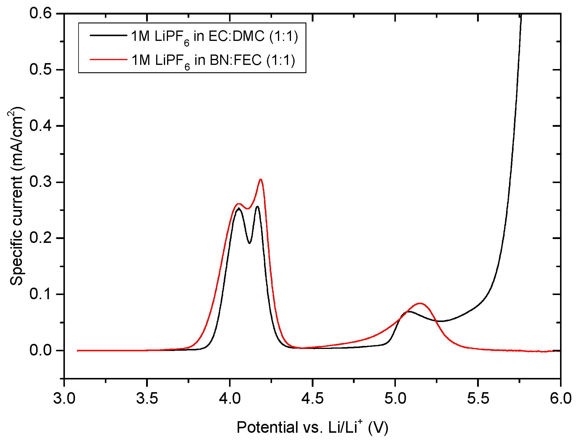
To determine the oxidative stability of the BN-based electrolytes, compared to the reference electrolyte, corresponding voltammograms were recorded using LMO as WE (Figure 2). A content of 50% of FEC was chosen to overcome the instability of nitriles towards metallic lithium and to ensure the passivation of the metallic lithium [13,61]. Whereas with organic carbonate-based electrolyte Li metal is stable, [62] with an EC content of only 50%, in the mixture the degradation of the electrolyte could not be inhibited. Therefore, EC:BN mixtures could not be investigated in combination with lithium metal. Nevertheless, this mixture should display the same oxidative stability (as confirmed by later full cell experiments). With 1M LiPF6 in EC:DMC (1:1) as reference electrolyte, the maxima of the de-insertion peaks of LMO are positioned at. 4.05 V vs. Li/Li+ and 4.16 V vs. Li/Li+ [63]. In this setup, the reference electrolyte was found to be electrochemically stable up to 4.90 V vs. Li/Li+ [64].
Compared to the reference electrolyte, the voltammogram of the cell containing 1M LiPF6 in BN:FEC (1:1) displays de-insertion peak maxima of LMO at 4.05 V vs. Li/Li+ and 4.19 V vs. Li/Li+. This electrolyte formulation shows electrochemical stability up to 4.50 V vs. Li/Li+, which is much higher compared to other literature known nitriles [65]. Furthermore, this result fits well with literature showing known density functional theory (DFT) calculations [55]. This behavior makes the combination of BN-based electrolytes with cathode materials, such as lithium nickel cobalt aluminum oxide (NCA) and NMC possible.
Cyclic voltammetry measurements in T44 graphite/lithium cells containing 1M LiPF6 in various BN:FEC solvent/co-solvent ratios were performed to determine the reductive stability of the considered electrolyte formulations vs. the anode (Figure 3).
The decomposition of FEC starts at a potential of 1.60 V vs. Li/Li+, reaching the peak maximum at a potential value of 1.50 V vs. Li/Li+ (Figure 3a–d). Due to the SEI formation in presence of FEC, the decomposition of the 1M LiPF6 in BN:FEC (1:1) (Figure 3a), 1M LiPF6 in BN:FEC (6:4) (Figure 3b), 1M LiPF6 in BN:FEC (7:3) (Figure 3c), 1M LiPF6 in BN:FEC (8:2) (Figure 3d) electrolyte formulations are inhibited, thus leading to the reversible intercalation and deintercalation of lithium ions into the graphite host structure, as indicated by the presence of the corresponding peaks (starting at a potential of 0.30 V vs. Li/Li+). Compared to the aforementioned electrolyte formulations, 1M LiPF6 in BN:FEC (9:1) electrolyte (Figure 3e) is not able to form an effective SEI on graphite and results in a severe decomposition. As a consequence, no intercalation/deintercalation steps take place. The amount of FEC seems not to be enough to protect the BN against decomposition on both T44 graphite and lithium electrode. Compared to FEC, the decomposition of in the 1M LiPF6 in EC:DMC (1:1) (Figure 3f) mixture starts at 0.9 V vs. Li/Li+ and the peak maximum is reached at 0.80 V vs. Li/Li+.
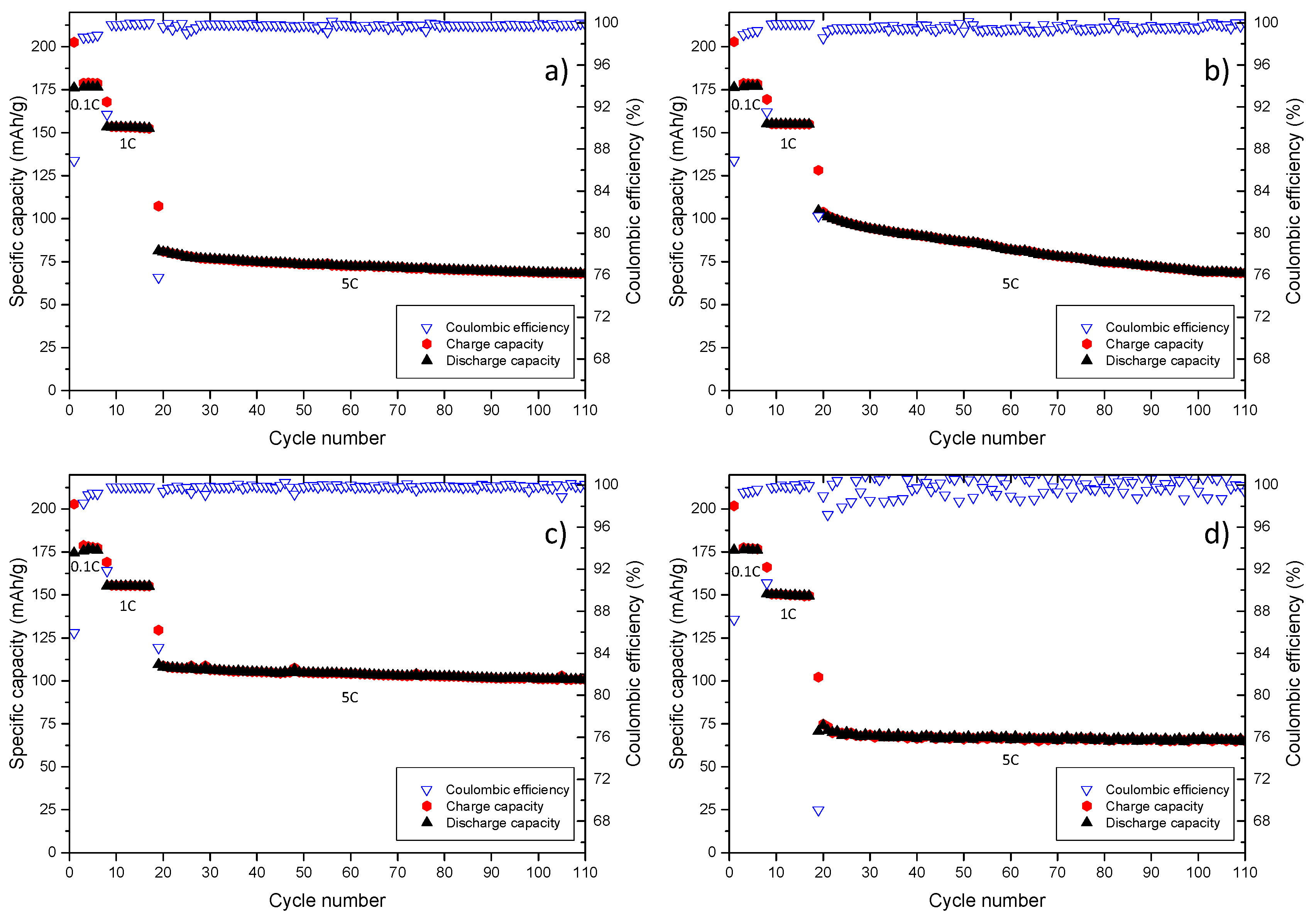
To prove the fast charging ability of the NMC/graphite cells containing afore mentioned BN-based electrolyte formulations, a C-rate evaluation up to 5C was performed, starting with five formation cycles at 0.1C. After the formation, 10 cycles at 1.0C were conducted, followed by 95 charge/discharge cycles with a C-rate of 5C. The obtained results are shown in Figure 4.
As depicted in Figure 4a, the NMC/graphite cell containing 1M LiPF6 in BN:EC (1:1) electrolyte, reaches a Coulombic efficiency of 87% in the first cycle (see Meister et al. for the meanings of efficiencies) [66]. The specific discharge capacity amounts to 176 mAh/g with a C-rate of 0.1 C in the first five cycles, whereas in the consecutive 10 charge/discharge cycles, a specific discharge capacity of 153 mAh/g with a Coulombic efficiency of 99% is achieved. After 15 cycles, the C-rate evaluation was started with a C-rate of 5C for each charge and discharge step for the consecutive 95 charge/discharge cycles. The specific discharge capacity displays a negligible fading and drops from 76 mAh/g in the 30th cycle to 68 mAh/g in the 110th cycle. The Coulombic efficiency drop in the 6th and 16th cycle is related to the change of the C-rate and observed in each chart in Figure 4. The cell containing 1M LiPF6 in BN:EC (7:3) + 1% FEC electrolyte formulation displays a first cycle Coulombic efficiency of 87%, as illustrated in Figure 4b. The specific discharge capacity amounts to 177 mAh/g for each cycle with a C-rate of 0.1C. A specific discharge capacity of 155 mAh/g with a Coulombic efficiency of 99% is reached in the following 10 charge/discharge cycles. In the C-rate evaluation, the specific discharge capacity shows a notable fading and drops from 93 mAh/g in cycle 30 to 68 mAh/g in cycle 110. The cell chemistry outlined in Figure 4c comprises of 1M LiPF6 in BN:EC (9:1) + 3% FEC electrolyte. The specific discharge capacity amounts to 176 mAh/g in the first five cycles using a C-rate of 0.1C, whereas the first cycle Coulombic efficiency amounts to 86%. Unlike other considered electrolyte formulations displayed in Figure 4, 99% Coulombic efficiency is not reached in the second but in the third cycle. The specific discharge capacity in the consecutive 10 charge/discharge cycles amounts to 155 mAh/g. During the 5C sequence, the capacity drops down to 105 mAh/g in the 30th cycle and decreases to 100 mAh/g in the 110th cycle, without a substantial fading. The cell containing 1M LiPF6 in EC:DMC (1:1) electrolyte formulation, (Figure 4d) displays a first Coulombic efficiency of 87%. The specific discharge capacity amounts to 176 mAh/g for each cycle with a C-rate of 0.1 C. The following 10 charge/discharge cycles display a specific discharge capacity of 155 mAh/g with a Coulombic efficiency of 99%. In the C-rate evaluation the specific discharge capacity drops from 67 mAh/g in the 30th cycle to 64 mAh/g in the 110th cycle. A comparison between the 1M LiPF6 in BN:EC (9:1) + 3% FEC and the reference electrolyte indicates a similar cycling performance at C-rates up to 1C and a superior higher performance of BN-based electrolyte at 5C. During cycling at 5C, the specific discharge capacity is decreased by 5% from 105 mAh/g to 100 mAh/g comparable to 4% with the reference electrolyte. In addition, the average specific discharge capacity at 5C is ≈ 103 mAh/g compared to ≈ 66 mAh/g for the reference electrolyte. The deviation amounts to 37 mAh/g (56%).
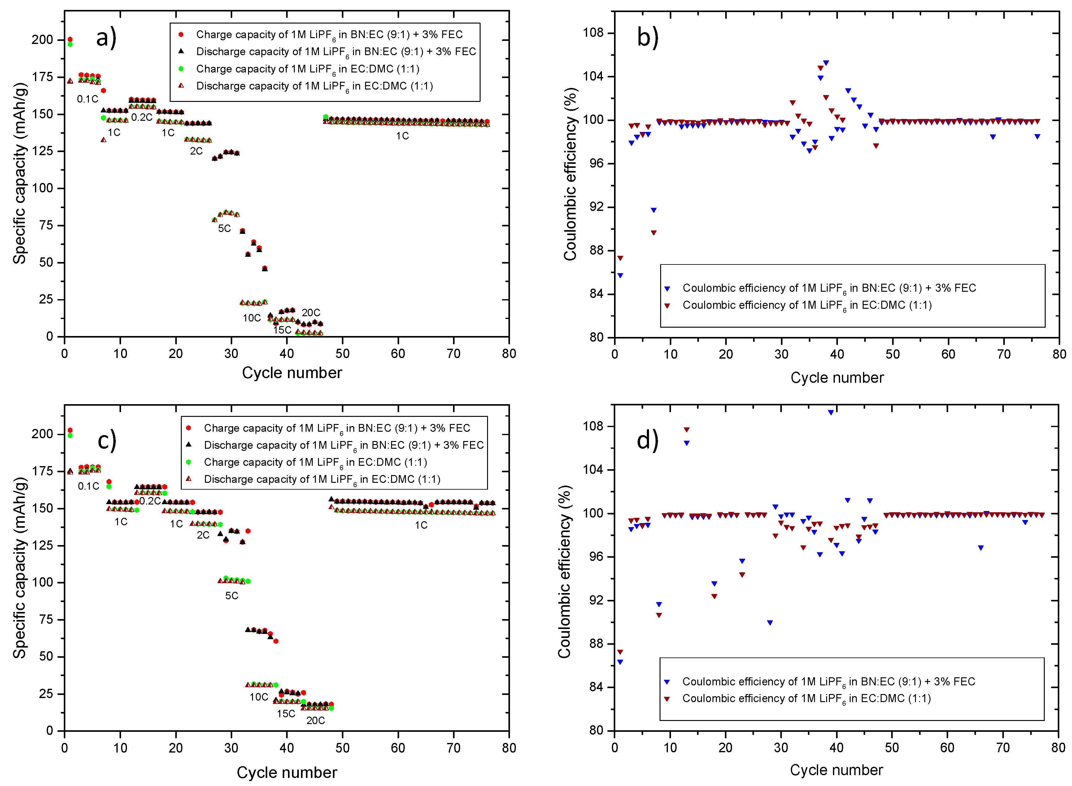
The obtained results show, that NMC/graphite cells containing 1M LiPF6 in BN:EC (9:1) + 3% FEC electrolyte display a remarkably stable cycling behavior at 5C. In addition, a C-rate evaluation, in NMC/graphite cells, up to 20C was carried out. Figure 5 shows the C-rate evaluation of 1M LiPF6 in BN:EC (9:1) + 3% FEC compared to the reference organic carbonate-based 1M LiPF6 in EC:DMC (1:1) electrolyte. Two types of C-rate evaluations were performed to determine whether the C-rate for charge (Figure 5a,b) or the C-rate for discharge (Figure 5c,d) has a more pronounced impact on the cycling stability of the NMC/graphite cells. In the first C-rate evaluation, the charge current is altered from 0.1C to 20C, whereas the C-rate of the discharge step was kept constant. In the second C-rate evaluation, the C-rate of the charge step remained constant while the C-rate of the discharge step was changed. The C-rate evaluation started with five formation cycles at 0.1C followed by five cycles at 1C.
When comparing the overall performance of the considered NMC/graphite cells with 1M LiPF6 in BN:EC (9:1) + 3% FEC and the 1M LiPF6 in EC:DMC (1:1) electrolytes, a better C-rate performance is achieved for the BN-based electrolyte containing cells, as depicted in in Figure 5a. Especially at a C-rate (charge step) of 5C and 10C, the specific discharge capacity is much higher for the BN-based electrolyte containing cell. At low C-rates (charge step), the specific discharge capacities of both electrolyte containing cells are quite similar. At 0.1C and 0.2C, the specific discharge capacity of the BN-based electrolyte containing cell has a value of 174 mAh/g and 160 mAh/g, respectively. On the other hand, the organic carbonate-based electrolyte containing cell delivers a specific discharge capacity of 172 mAh/g at 0.1 C and 154 mAh/g at 0.2C, which is nearly similar to the cell containing 1M LiPF6 in BN:EC (9:1) + 3% FEC. At 5C and 10C, the better electrochemical performance of the BN-based electrolyte containing cell becomes clear, as a discharge capacity of 125 mAh/g is reached, compared to the 82 mAh/g for the organic carbonate-based counterpart. Even though the specific discharge capacity of the BN-based cell is not constant at 10C, the specific discharge capacity value is 62 mAh/g, is higher compared to the 21 mAh/g obtained in the cell with the organic carbonate-based electrolyte. At a C-rate (charge step) of 20C, the BN-based electrolyte containing cell delivers a specific capacity of 8 mAh/g. The decrease of C-rate to 1C results in a stable cycling performance for both considered cell chemistries. Nevertheless, the cell containing BN-based formulation has a slightly higher specific discharge capacity. The corresponding Coulombic efficiency values are depicted in Figure 5b.
For the C-rate (of the discharge step) performance, a similar behavior can be observed (Figure 5c). At low C-rates (of the discharge step), the electrochemical performance of both cells is nearly similar, whereas with increasing C-rate (discharge step), the cell with the BN-based electrolyte shows a much better performance. At 5C, a specific discharge capacity of 135 mAh/g is achieved. Increasing the discharge rate up to 10C, a value of 67 mAh/g is reached for the BN-based electrolyte containing cell. On the other side, the specific discharge capacity is much lower (101 mAh/g and 29 mAh/g, respectively) for the organic carbonate-based electrolyte containing cell. The decrease of the C-rate (discharge step) to 1C, results in stable cycling performance for both cell chemistries. Nevertheless, the cell containing BN-based electrolyte shows a higher specific discharge capacity (155 mAh/g vs. 144 mAh/g) at a C-rate (charge and discharge step) of one 1C after the 100th cycle. The corresponding Coulombic efficiency values are depicted in Figure 5d.
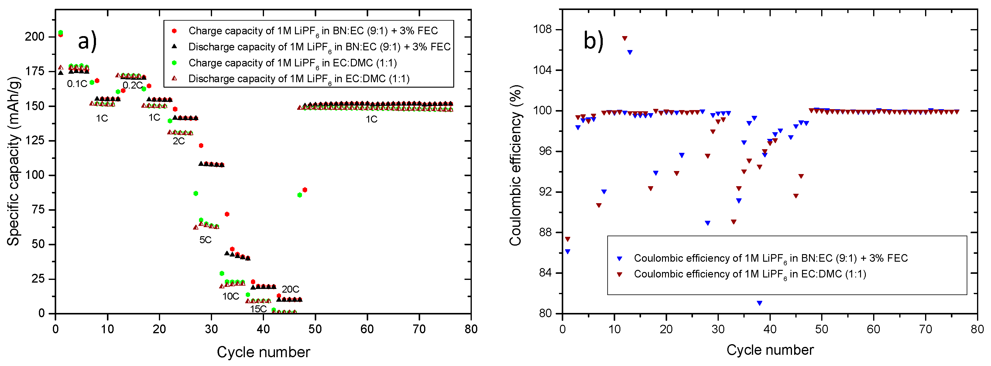
For both C-rate (both the charge and the discharge step) evaluations, it was shown that the cells containing a BN-based electrolyte outperform the organic carbonate-based counterpart. This is especially observed, at 5C and 10C. Even at higher C-rates (15C and 20C), a cell containing 1M LiPF6 in BN:EC (9:1) + 3% FEC electrolyte shows better electrochemical performance compared to the reference organic carbonate-based electrolyte counterpart. The simultaneous charge/discharge behavior of the considered BN-based cell and organic carbonate-based cell at different C-rates was evaluated further. As depicted in Figure 6, a similar behavior in terms of specific discharge capacity can be observed. An increase in the C-rate (of the charge and discharge step) results in higher difference between the specific discharge capacities of the cells containing BN-based electrolyte and the ones with the organic carbonate-based electrolyte. The cell containing BN as solvent shows much better cycling performance at higher C-rates (both charge and discharge), compared to the state-of-the-art electrolyte containing counterpart. At 1C, a specific discharge capacity of 154 mAh/g and 150 mAh/g for the cell containing organic carbonate-based electrolyte is achieved. By increasing the C-rate (both the charge and the discharge step) to 2C, the specific discharge capacity reach values of 140 mAh/g and 129 mAh/g, respectively, whereas an increase in the C-rate (both the charge and the discharge step to 10C results in a specific capacity value of 42 mAh/g and 22 mAh/g, respectively. After increasing the C-rate (both the charge and the discharge step) to 20C, the BN-based electrolyte containing cell reaches a specific capacity of 9 mAh/g in contrast to 1 mAh/g for the state-of-the-art electrolyte containing counterpart. After the C-rate (both the charge and the discharge step) is decreased to 1C again, both electrolyte containing cells exhibit a stable cycling behavior (for both Coulombic efficiency as well as specific discharge capacity). During cycling with a C-rate (both the charge and the discharge step) of 1C, the cells deliver specific discharge capacity of 151 mAh/g in case of the BN-based electrolyte and 148 mAh/g for the organic carbonate-based electrolyte. The corresponding Coulombic efficiency values are depicted in Figure 6b. Table 1 summarizes the results obtained from graphs presented in Figure 5 and Figure 6 for the NMC/graphite cells cycled with 1M LiPF6 in BN:EC (9:1) + 3% FEC and 1M LiPF6 in EC:DMC (1:1) electrolytes, respectively.
As data listed in Table 2 show, the cells containing BN-based electrolytes deliver higher specific capacity values at higher C-rate compared to their state-of-the-art electrolyte counterparts. The C-rate (discharge step) evaluation setup leads to higher specific discharge capacities compared to the other two C-rate evaluations. This might be explained on the basis of the intercalation and deintercalation steps on graphite: the deintercalation process for graphite is always favored therefore, higher discharge capacities can be reached for both electrolytes [57]. Based on the obtained results, the main use for the BN-based electrolyte formulation would be in applications with high demands to power, fast charge ability or even both.
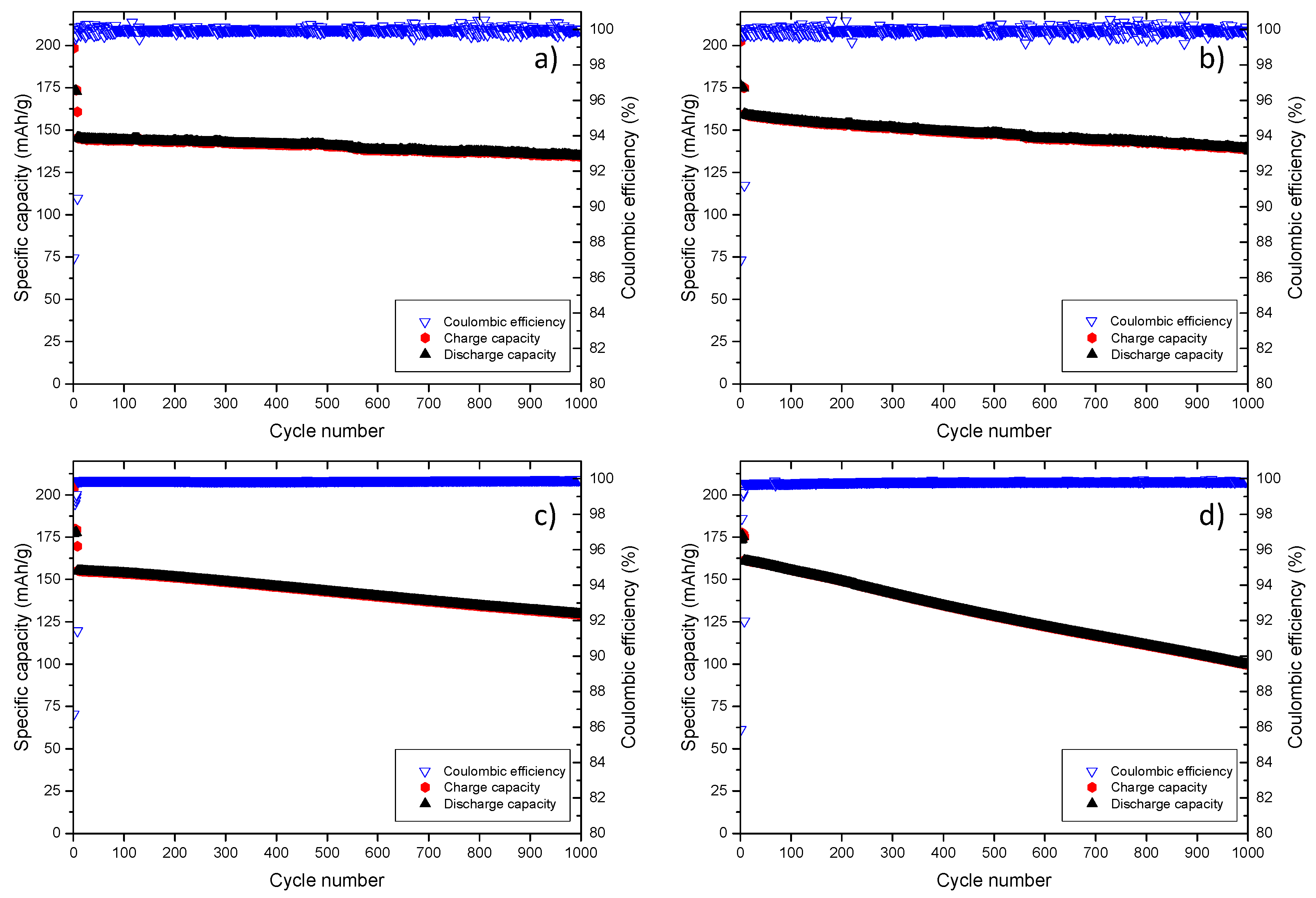
As BN:EC (9:1) + 3% FEC electrolyte containing cells show remarkable C-rate performance, long-time cycling experiments were conducted to enable deeper characterization of the electrochemical behavior of the considered cell chemistry. In Figure 7, two different long-term cycling measurements (1000 charge/discharge cycles) were performed for the BN-based electrolyte containing NMC/graphite cell as well as the state-of-the-art electrolyte containing counterpart.
The afore mentioned C-rate evaluation was performed without using a constant voltage (CV) step after the charge step. A CV step is typically used to enhance the capacity of the graphite slightly, making sure, that the graphite is fully lithiated [67].
The long-time cycling measurements depicted in Figure 7 show that, without CV step, the long term cycling performance of the 1M LiPF6 in BN:EC (9:1) + 3% FEC containing cells (Figure 7c) is comparable to the state of the art electrolyte based on 1M LiPF6 in EC:DMC (1:1) cell counterparts, as depicted in Figure 7a. The 1st cycle Coulombic efficiency of the cell containing 1M LiPF6 in EC:DMC (1:1) electrolyte (87%) matches the Coulombic efficiency resulting with the 1M LiPF6 in BN:EC (9:1) + 3% FEC electrolyte (87% Coulombic efficiency). Ninety-nine percent Coulombic efficiency is reached in the second cycle for the state-of-the-art electrolyte as well as for the BN-based counterpart. From this point onwards, the Coulombic efficiency values of both cells containing considered electrolytes are nearly similar, amounting to ≈99% during the long-term cycling performance. In the initial cycles, in which SEI formation takes place, a specific discharge capacity of 177 mAh/g is reached for the cell containing BN-based electrolyte, whereas the one with the EC:DMC-based electrolyte shows a specific discharge capacity of 173 mAh/g. After the initial cycles (five cycles with 0.1C), the cells were cycled with 1C until the 1000th charge/discharge cycle. For both cell chemistries, a stable long-term cycling is observed, with an absence of strong fading in capacity. In the 10th cycle, a specific discharge capacity of 155 mAh/g is reached and decreases slightly to 129 mAh/g in the last (1000th) cycle, for the cell with 1M LiPF6 in BN:EC (9:1) + 3% FEC as electrolyte. For the cell containing 1M LiPF6 in EC:DMC (1:1) as electrolyte, a specific discharge capacity of 145 mAh/g in the 10th cycle and 135 mAh/g in the 1000th cycle is reached. Comparing the 10th cycle with the 1000th cycle, both electrolytes reach over 80% of the initial capacity, meeting the automotive requirements (80% state of health after 1000 charge/discharge cycles).
For the long-term evaluations comprising a current-limited constant voltage step the results are different. The long-term cycling performance of the 1M LiPF6 in BN:EC (9:1) + 3% FEC (Figure 7d) is decreased compared to the state-of-the-art electrolyte-based cell depicted in Figure 7b. The 1st cycle Coulombic efficiency of the 1M LiPF6 in EC:DMC (1:1) electrolyte (87%) containing cell is similar to the Coulombic efficiency obtained for the 1M LiPF6 in BN:EC (9:1) + 3% FEC electrolyte (86% Coulombic efficiency) based counterpart. The Coulombic efficiency of 99% for the state-of-the-art electrolyte containing cell is reached in the second cycle. For the BN-based electrolyte containing cell, a Coulombic efficiency amounts to o 99% only in the 4th cycle. From this point onwards, the Coulombic efficiency values of both electrolyte containing cells are nearly similar, >99% prolong the long-term cycling. During the initial cycles, a specific discharge capacity of 174 mAh/g is reached for the BN-based electrolyte containing cell, whereas the one with the EC:DMC-based electrolytes displays a specific discharge capacity of 175 mAh/g. After the initial cycles (five charge/discharge cycles with 0.1C), the cells were cycled at 1C until the 1000th cycle. Both cells passed the long-term cycling procedure, thus indicating a good cycling performance. However, a slight fading of the cell with the BN-based electrolyte (Figure 7d) is noticeable. In the 10th cycle, a specific discharge capacity of 161 mAh/g is reached and decreases to 100 mAh/g in the 1000th cycle, for the cell with 1M LiPF6 in BN:EC (9:1) + 3% FEC as electrolyte. For the cell containing 1M LiPF6 in EC:DMC (1:1) as electrolyte, a specific discharge capacity of 159 mAh/g in the 10th cycle and 139 mAh/g in the 1000th cycle is reached. Comparing the 10th cycle with the 1000th cycle only the state of the art electrolyte has reached over 80% of the initial capacity, meeting the automotive requirements [68]. Table 3 summarizes afore mentioned cycling performance and comperes both cycling procedures (with and without CV step).
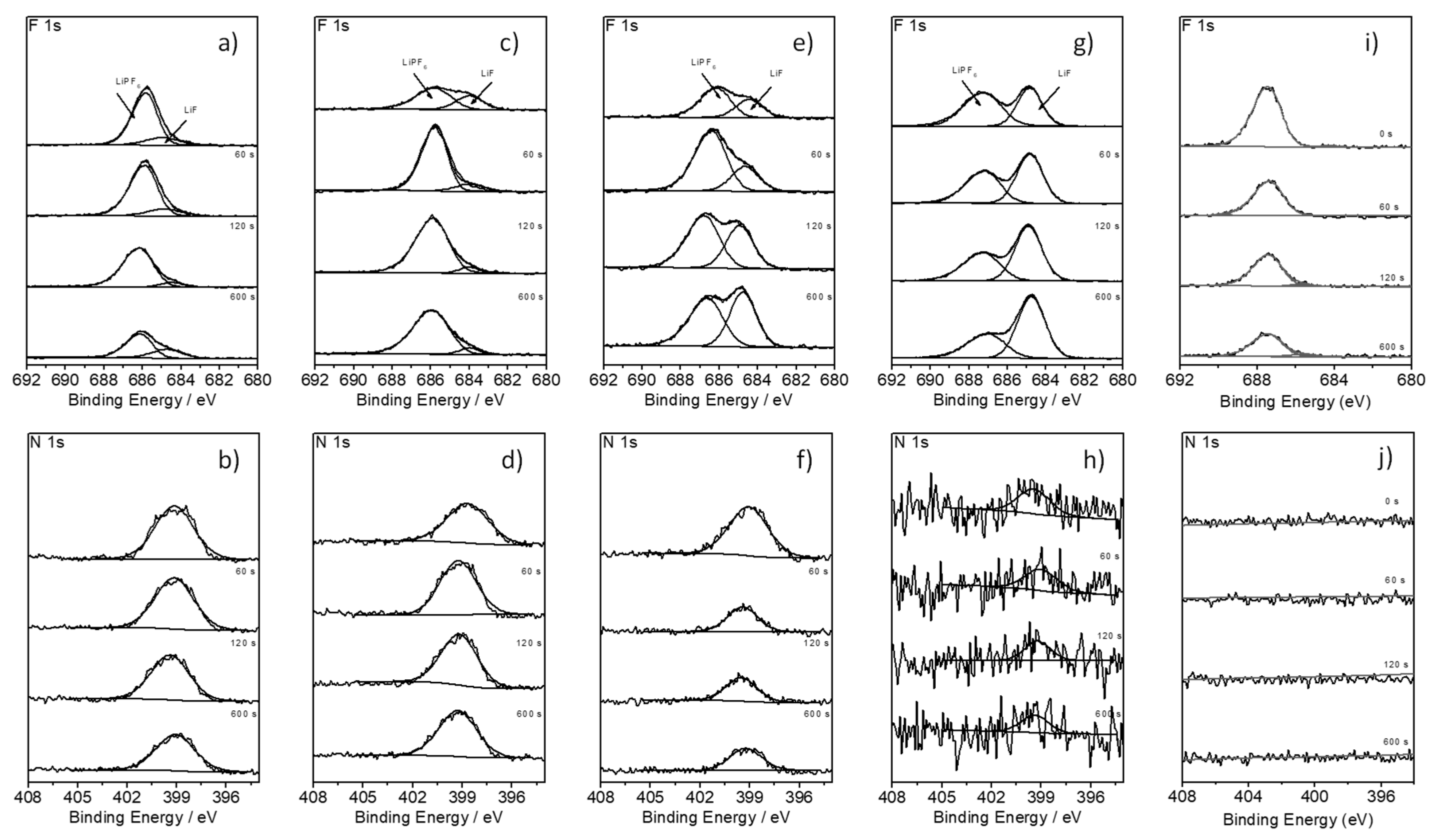
The capacity retention values show, that a CV step deteriorates the electrochemical performance of the NMC/graphite cells. The same effect is observed with the reference electrolyte containing cell however, the effect is less pronounced. This outcome is explained by the time at which the cells remain at the cut-off voltage. For the cells cycled with a CV step, this duration is much larger and is leading to a pronounced degradation (shorter lifespan) of these cells. To correlate the obtained results with the surface chemistry of electrodes containing BN-based electrolyte, XPS sputter depth profiling of graphite electrodes was performed, to prove the stability of the electrolyte towards graphite. The electrochemical decomposition of considered BN-based electrolyte formulations on the graphite surface was analyzed by means of XPS (see Figure 8).
Figure 8 depicts the XPS F 1s and N 1s core spectra of graphite electrode-based cells cycled in presence of a,b) 1M LiPF6 in BN; c,d) 1M LiPF6 in BN with 5% FEC; e,f) 1M LiPF6 in BN:EC (9:1) + 2% FEC; as well as g,h) 1M LiPF6 in BN:EC (9:1) + 3% FEC as electrolyte. As reference spectra, the XPS F 1s and N 1s core spectra of a pristine graphite electrode (Figure 8i,j) are shown. In the F 1s spectra (Figure 8i), a signal located at 687 eV is observable, which can be attributed to the polyvinylidene difluoride (PVdF) binder [69]. The decrease of the peak intensity during sputtering is related to the decomposition of the binder during XPS measurement [70]. On the other hand, no nitrogen signal was observed on the pristine electrode surface (Figure 8j). In the F 1s spectra of the cycled electrodes (Figure 8a,c,e,g), an additional signal attributed to lithium fluoride (LiF), formed due to the decomposition of the conducting salt LiPF6, occurs at 685 eV. As depicted in Figure 8a,c the amount of LiF remains unaffected relatively to the intensity of the PVdF peak with increasing the sputter time. This could be explained by a limited degradation of LiPF6 in the BN-based electrolytes without EC. Due to the severe decomposition of BN, the corresponding peaks overlap the peaks assigned to the decomposition of LiPF6. In addition, in the N1s core spectra of the electrodes containing pure BN-based electrolyte (Figure 8b,d) a signal at 399 eV is observed, attributed to the decomposition of the nitrile during cycling. In the absence of BN decomposition, the peak of LiF increases relatively to the PVdF peak with increasing the sputter time (Figure 8e,g), as LiF is the main component of the inorganic part of the SEI [70]. The increase of the LiF peak indicates absence of decomposition, meaning that a SEI was formed on graphite surface. Nevertheless, the N 1s core spectra of the graphite electrode cycled with 1M LiPF6 in BN:EC (9:1) + 2% FEC, exhibit a peak 399 eV related to BN decomposition, thus indicating that the formed SEI does not fully prevent the decomposition of the nitrile. By adding 3% FEC to the BN:EC (9:1) electrolyte formulation, the peak in the corresponding N1s core spectrum at 399 eV disappears (Figure 8h), thus indicating an effective SEI formation, which prevents BN against decomposition. Table 4 lists the corresponding surface concentration given in arbitrary units (a.u.).
For the electrodes with pure BN-based electrolyte, as well as for the electrolyte formulation containing 5% FEC, only small amounts of LiF were detected. The origin of the spectra can be dedicated to the decomposition of small amounts of the conducting salt LiPF6. The N 1s surface concentration for both electrolytes indicates a severe decomposition of BN. Without formation of an effective SEI, an ongoing decomposition of the solvent (BN) takes place. For the electrolyte formulations BN:EC (9:1) with addition of 2% and 3% FEC respectively, the amount of LiF increases during sputtering [70,71]. The intensity of the N 1s signal decreases for both electrolytes corresponding to a less pronounced decomposition of the BN-solvent. However, regarding the N 1s surface concentration, the addition of 2% FEC is not enough for the formation of an effective SEI on graphite. The N 1s surface concentration of the formulation containing 3% FEC is comparable to the N 1s surface concentration of the reference electrode, however, both do not show a significant signal.

4. Conclusions

With two successfully tuned BN-based electrolyte formulations (one used in half-cell and the other in full-cell configuration), the decomposition on both lithium metal and graphite, could be prevented. Both electrolytes were comparable or even better compared to the state-of-the-art organic carbonate-based electrolyte. In half cell experiments, 1M LiPF6 in BN:FEC (1:1) containing cell showed the most promising results. EC was compared to FEC, due to its lower passivation capability towards metallic lithium, not suitable to protect BN against decomposition. Nevertheless, 1M LiPF6 in BN:FEC formulation showed lower ion conductivity values compared to BN:EC counterparts. Especially at low temperatures around 0 °C, the conductivity of the BN:EC-based electrolytes was at least 32% higher (7.69 mS/cm) compared to the BN:FEC-based and the organic carbonate-based electrolyte (5.83 mS/cm). Since the main focus of this paper is related to the possible the automotive applicability of BN, investigations in NMC/graphite cells containing BN:EC-based electrolytes were studied in detail. In each investigation, the cell containing 1M LiPF6 in BN:EC (9:1) + 3% FEC showed a superior high performance compared to the organic-carbonate-based counterpart. To match automotive requirements, a C-rate evaluation of 5C was performed. It was shown, that the average specific discharge capacity at 5C amounted to ≈103 mAh/g for the investigated BN-based electrolyte containing cell, which was nearly twice the capacity of the cell with the reference electrolyte (≈66 mAh/g). Further, a C-rate evaluation up to 20C was performed. The cells containing investigated BN-based electrolyte formulation showed a superior C-rate performance compared to the organic state of the art counterpart. In addition, the CV step in the CCCV measurements, typically used in case of organic carbonate-based electrolyte containing cells, was investigated. It was found out, that a CV step increases the charge/discharge capacity at the beginning of the cycling procedure so that more lithium ions can be intercalated into graphite. Nevertheless, the CV step reduces the overall cycle-life of the cell as well, due to the pronounced electrolyte degradation. In the long-term cycling experiment (Figure 7c,d) the advantage of the CV step is lost after the 150th cycle. From the 150th cycle onwards the capacity of the cell cycled without CV step is higher compared to the cell cycled with CV step.
XPS analysis of the NMC electrodes complements well to the electrochemical characterization of the BN-based electrolytes, showing that a minimum amount of 3% FEC is needed to prevent the BN-based electrolyte formulation of 1M LiPF6 in BN:EC (9:1) from decomposition on graphite in NMC/graphite cell setup.

Author Contributions

P.H., I.C.-L. and M.W. conceived and designed theexperiments; P.H. and L.I. performed the experiments; P.H., L.I., I.C.-L. and M.W. analyzed the data; P.H. and I.C.-L. wrote the paper.

Funding

Financial support by the German Federal Ministry for Education and Research (BMBF) within the project Electrolyte Lab 4E (project reference 03X4632) is gratefully acknowledged.

Conflicts of Interest

The authors declare no conflict of interest.

References

  1. Winter, M.; Brodd, R.J. What are batteries, fuel cells, and supercapacitors? Chem. Rev. 2004, 104, 4245–4269. [Google Scholar] [CrossRef] [PubMed]
  2. Andre, D.; Kim, S.-J.; Lamp, P.; Lux, S.F.; Maglia, F.; Paschos, O.; Stiaszny, B. Future generations of cathode materials: an automotive industry perspective. J. Mater. Chem. A 2015, 3, 6709–6732. [Google Scholar] [CrossRef]
  3. Schmuch, R.; Wagner, R.; Hörpel, G.; Placke, T.; Winter, M. Performance and cost of materials for lithium-based rechargeable automotive batteries. Nat. Energy 2018, 3, 267. [Google Scholar] [CrossRef]
  4. Winter, M.; Barnett, B.; Xu, K. Before Li ion batteries. Chem. Rev. 2018, 118, 11433–11456. [Google Scholar] [CrossRef] [PubMed]
  5. Lu, L.; Han, X.; Li, J.; Hua, J.; Ouyang, M. A review on the key issues for lithium-ion battery management in electric vehicles. J. Power Sources 2013, 226, 272–288. [Google Scholar] [CrossRef]
  6. Placke, T.; Kloepsch, R.; Dühnen, S.; Winter, M. Lithium ion, lithium metal, and alternative rechargeable battery technologies: the odyssey for high energy density. J. Solid State Electrochem. 2017, 21, 1939–1964. [Google Scholar] [CrossRef]
  7. Betz, J.; Bieker, G.; Meister, P.; Placke, T.; Winter, M.; Schmuch, R. Theoretical versus Practical Energy: A Plea for More Transparency in the Energy Calculation of Different Rechargeable Battery Systems. Adv. Energy Mater. 2019, 9, 1803170. [Google Scholar] [CrossRef]
  8. Wagner, R.; Preschitschek, N.; Passerini, S.; Leker, J.; Winter, M. Current research trends and prospects among the various materials and designs used in lithium-based batteries. J. Appl. Electrochem. 2013, 43, 481–496. [Google Scholar] [CrossRef]
  9. Xu, K. Nonaqueous liquid electrolytes for lithium-based rechargeable batteries. Chem. Rev. 2004, 104, 4303–4417. [Google Scholar] [CrossRef]
  10. Wen, J.; Yu, Y.; Chen, C. A Review on Lithium-Ion Batteries Safety Issues: Existing Problems and Possible Solutions. Mater. Express 2012, 2, 197–212. [Google Scholar] [CrossRef]
  11. Wrodnigg, G.H.; Besenhard, J.O.; Winter, M. Ethylene sulfite as electrolyte additive for lithium-ion cells with graphitic anodes. J. Electrochem. Soc. 1999, 146, 470–472. [Google Scholar] [CrossRef]
  12. Chawla, N.; Bharti, N.; Singh, S. Recent advances in non-flammable electrolytes for safer lithium-ion batteries. Batteries 2019, 5, 19. [Google Scholar] [CrossRef]
  13. Xu, K. Electrolytes and Interphases in Li-Ion Batteries and Beyond. Chem. Rev. 2014, 114, 11503–11618. [Google Scholar] [CrossRef] [PubMed]
  14. Cekic-Laskovic, I.; von Aspern, N.; Imholt, L.; Kaymaksiz, S.; Oldiges, K.; Rad, B.R.; Winter, M. Synergistic effect of blended components in nonaqueous electrolytes for lithium ion batteries. Top. Curr. Chem. 2017, 375, 37. [Google Scholar] [CrossRef] [PubMed]
  15. Xue, L.; Lee, S.-Y.; Zhao, Z.; Angell, C.A. Sulfone-carbonate ternary electrolyte with further increased capacity retention and burn resistance for high voltage lithium ion batteries. J. Power Sources 2015, 295, 190–196. [Google Scholar] [CrossRef] [Green Version]
  16. Lewandowski, A.; Kurc, B.; Stepniak, I.; Swiderska-Mocek, A. Properties of Li-graphite and LiFePO4 electrodes in LiPF6–sulfolane electrolyte. Electrochim. Acta 2011, 56, 5972–5978. [Google Scholar] [CrossRef]
  17. Abu-Lebdeh, Y.; Davidson, I. High-Voltage Electrolytes Based on Adiponitrile for Li-Ion Batteries. J. Electrochem. Soc. 2009, 156, A60–A65. [Google Scholar] [CrossRef]
  18. Winter, M.; Novák, P. Chloroethylene Carbonate, a Solvent for Lithium-Ion Cells, Evolving CO2 during Reduction. J. Electrochem. Soc. 1998, 145, L27–L30. [Google Scholar] [CrossRef]
  19. Wrodnigg, G.H.; Besenhard, J.O.; Winter, M. Cyclic and acyclic sulfites: new solvents and electrolyte additives for lithium ion batteries with graphitic anodes? J. Power Sources 2001, 97, 592–594. [Google Scholar] [CrossRef]
  20. Krämer, E.; Passerini, S.; Winter, M. Dependency of aluminum collector corrosion in lithium ion batteries on the electrolyte solvent. ECS Electrochem. Lett. 2012, 1, C9–C11. [Google Scholar] [CrossRef]
  21. Winter, M.; Moeller, K.-C.; Besenhard, J.O. Lithium Batteries: Science and Technology; Nazri, G.A., Pistoia, G., Eds.; Kluwer Academic Publishers: New York, NY, USA, 2004; p. 144. [Google Scholar]
  22. Safa, M.; Chamaani, A.; Chawla, N.; El-Zahab, B. Polymeric ionic liquid gel electrolyte for room temperature lithium battery applications. Electrochim. Acta 2016, 213, 587–593. [Google Scholar] [CrossRef]
  23. Safa, M.; Adelowo, E.; Chamaani, A.; Chawla, N.; Herndon, M.; Baboukani, A.; Wang, C.; El-Zahab, B. Poly (Ionic Liquid) based Composite Gel Electrolyte for Lithium Batteries. ChemElectroChem 2019, 6, 3319–3332. [Google Scholar] [CrossRef]
  24. Hilbig, P.; Ibing, L.; Wagner, R.; Winter, M.; Cekic-Laskovic, I. Ethyl methyl sulfone-based electrolytes for lithium ion battery applications. Energies 2017, 10, 1312. [Google Scholar] [CrossRef]
  25. Yamada, Y.; Furukawa, K.; Sodeyama, K.; Kikuchi, K.; Yaegashi, M.; Tateyama, Y.; Yamada, A. Unusual Stability of Acetonitrile-Based Superconcentrated Electrolytes for Fast-Charging Lithium-Ion Batteries. J. Am.Chem. Soc. 2014, 136, 5039–5046. [Google Scholar] [CrossRef]
  26. Isken, P.; Dippel, C.; Schmitz, R.; Schmitz, R.W.; Kunze, M.; Passerini, S.; Winter, M.; Lex-Balducci, A. High flash point electrolyte for use in lithium-ion batteries. Electrochim. Acta 2011, 56, 7530–7535. [Google Scholar] [CrossRef]
  27. Schmitz, R.W.; Murmann, P.; Schmitz, R.; Müller, R.; Krämer, L.; Kasnatscheew, J.; Isken, P.; Niehoff, P.; Nowak, S.; Röschenthaler, G.-V.; et al. Investigations on novel electrolytes, solvents and SEI additives for use in lithium-ion batteries: Systematic electrochemical characterization and detailed analysis by spectroscopic methods. Prog. Solid State Chem. 2014, 42, 65–84. [Google Scholar] [CrossRef]
  28. Korepp, C.; Santner, H.; Fujii, T.; Ue, M.; Besenhard, J.; Möller, K.-C.; Winter, M. 2-Cyanofuran—A novel vinylene electrolyte additive for PC-based electrolytes in lithium-ion batteries. J. Power Sources 2006, 158, 578–582. [Google Scholar] [CrossRef]
  29. Brox, S.; Röser, S.; Streipert, B.; Hildebrand, S.; Rodehorst, U.; Qi, X.; Wagner, R.; Winter, M.; Cekic-Laskovic, I. Innovative, Non-Corrosive LiTFSI Cyanoester-Based Electrolyte for Safer 4 V Lithium-Ion Batteries. ChemElectroChem 2017, 4, 304–309. [Google Scholar] [CrossRef]
  30. Brox, S.; Röser, S.; Husch, T.; Hildebrand, S.; Fromm, O.; Korth, M.; Winter, M.; Cekic-Laskovic, I. Alternative Single-Solvent Electrolytes Based on Cyanoesters for Safer Lithium-Ion Batteries. ChemSusChem 2016, 9, 1704–1711. [Google Scholar] [CrossRef]
  31. Pohl, B.; Grünebaum, M.; Drews, M.; Passerini, S.; Winter, M.; Wiemhöfer, H.D. Nitrile functionalized silyl ether with dissolved LiTFSI as new electrolyte solvent for lithium-ion batteries. Electrochim. Acta 2015, 180, 795–800. [Google Scholar] [CrossRef]
  32. Kirshnamoorthy, A.N.; Oldiges, K.; Winter, M.; Heuer, A.; Cekic-Laskovic, I.; Holm, C.; Smiatek, J. Electrolyte solvents for high voltage lithium ion batteries: ion correlation and specific anion effects in adiponitrile. Chem. Chem. Phys. 2018, 20, 25701–25715. [Google Scholar] [CrossRef] [PubMed]
  33. Oldiges, K.; von Aspern, N.; Cekic-Laskovic, I.; Winter, M.; Brunklaus, G. Impact of Trifluoromethylation of Adiponitrile on Aluminum Dissolution Behavior in Dinitrile-Based Electrolytes. J. Electrochem. Soc. 2018, 165, A3773–A3781. [Google Scholar] [CrossRef]
  34. Santner, H.J.; Möller, K.C.; Ivanco, J.; Ramsey, M.G.; Netzer, F.P.; Yamaguchi, S.; Besenhard, J.O.; Winter, M. Acrylic acid nitrile, a film-forming electrolyte component for lithium-ion batteries, which belongs to the family of additives containing vinyl groups. J. Power Sources 2003, 119, 368–372. [Google Scholar] [CrossRef]
  35. Peled, E. The Electrochemical Behavior of Alkali and Alkaline Earth Metals in Nonaqueous Battery Systems—The Solid Electrolyte Interphase Model. J. Electrochem. Soc. 1979, 126, 2047–2051. [Google Scholar] [CrossRef]
  36. Peled, E.; Golodnitsky, D.; Ardel, G. Advanced model for solid electrolyte interphase electrodes in liquid and polymer electrolytes. J. Electrochem. Soc. 1997, 144, L208–L210. [Google Scholar] [CrossRef]
  37. Zhang, S.S.; Ding, M.S.; Xu, K.; Allen, J.; Jow, T.R. Understanding solid electrolyte interface film formation on graphite electrodes. Electrochem. Solid State Lett. 2001, 4, A206–A208. [Google Scholar] [CrossRef]
  38. Winter, M.; Appel, W.K.; Evers, B.; Hodal, T.; Moller, K.C.; Schneider, I.; Wachtler, M.; Wagner, M.R.; Wrodnigg, G.H.; Besenhard, J.O. Studies on the anode/electrolyte interface in lithium ion batteries. Chem. Mon. 2001, 132, 473–486. [Google Scholar] [CrossRef]
  39. Li, F.S.; Wu, Y.S.; Chou, J.; Winter, M.; Wu, N.L. A mechanically robust and highly ion-conductive polymer-blend coating for high-power and long-life lithium-ion battery anodes. Adv. Mater 2015, 27, 130–137. [Google Scholar] [CrossRef]
  40. Winter, M. The solid electrolyte interphase–the most important and the least understood solid electrolyte in rechargeable Li batteries. Z. Phys. Chem. 2009, 223, 1395–1406. [Google Scholar] [CrossRef]
  41. Santner, H.J.; Korepp, C.; Winter, M.; Besenhard, J.O.; Möller, K.-C. In-situ FTIR investigations on the reduction of vinylene electrolyte additives suitable for use in lithium-ion batteries. Anal. Bioanal. Chem. 2004, 379, 266–271. [Google Scholar] [CrossRef]
  42. Märkle, W.; Lu, C.-Y.; Novák, P. Morphology of the Solid Electrolyte Interphase on Graphite in Dependency on the Formation Current. J. Electrochem. Soc. 2011, 158, A1478–A1482. [Google Scholar] [CrossRef]
  43. Besenhard, J.O.; Wagner, M.W.; Winter, M.; Jannakoudakis, A.D.; Jannakoudakis, P.D.; Theodoridou, E. Inorganic Film-Forming Electrolyte Additives Improving the Cycling Behavior of Metallic Lithium Electrodes and the Self-Discharge of Carbon Lithium Electrodes. J. Power Sources 1993, 44, 413–420. [Google Scholar] [CrossRef]
  44. Wang, K.; Xing, L.; Zhi, H.; Cai, Y.; Yan, Z.; Cai, D.; Zhou, H.; Li, W. High stability graphite/electrolyte interface created by a novel electrolyte additive: A theoretical and experimental study. Electrochim. Acta 2018, 262, 226–232. [Google Scholar] [CrossRef]
  45. Wang, Y.; Nakamura, S.; Tasaki, K.; Balbuena, P.B. Theoretical Studies to Understand Surface Chemistry on Carbon Anodes for Lithium-Ion Batteries:  How Does Vinylene Carbonate Play Its Role as an Electrolyte Additive? J. Am.Chem. Soc. 2002, 124, 4408–4421. [Google Scholar] [CrossRef] [PubMed]
  46. Aurbach, D.; Gamolsky, K.; Markovsky, B.; Gofer, Y.; Schmidt, M.; Heider, U. On the use of vinylene carbonate (VC) as an additive to electrolyte solutions for Li-ion batteries. Electrochim. Acta 2002, 47, 1423–1439. [Google Scholar] [CrossRef]
  47. Zhang, L.; Ma, Y.; Cheng, X.; Zuo, P.; Cui, Y.; Guan, T.; Du, C.; Gao, Y.; Yin, G. Enhancement of high voltage cycling performance and thermal stability of LiNi1/3Co1/3Mn1/3O2 cathode by use of boron-based additives. Solid State Ionics 2014, 263, 146–151. [Google Scholar] [CrossRef]
  48. Meister, P.; Qi, X.; Kloepsch, R.; Krämer, E.; Streipert, B.; Winter, M.; Placke, T. Anodic Behavior of the Aluminum Current Collector in Imide-Based Electrolytes: Influence of Solvent, Operating Temperature, and Native Oxide-Layer Thickness. ChemSusChem 2017, 10, 804–814. [Google Scholar] [CrossRef]
  49. Markevich, E.; Salitra, G.; Aurbach, D. Fluoroethylene carbonate as an important component for the formation of an effective solid electrolyte interphase on anodes and cathodes for advanced Li-ion batteries. ACS Energy Lett. 2017, 2, 1337–1345. [Google Scholar] [CrossRef]
  50. Zugmann, S.; Moosbauer, D.; Amereller, M.; Schreiner, C.; Wudy, F.; Schmitz, R.; Schmitz, R.; Isken, P.; Dippel, C.; Muller, R.; et al. Electrochemical characterizaiton of electrolytes for lithium-ion batteries based on lithium difluoromono(oxalato)borate. J. Power Sources 2011, 196, 1417–1424. [Google Scholar] [CrossRef]
  51. Dagger, T.; Grützke, M.; Reichert, M.; Haetge, J.; Nowak, S.; Winter, M.; Schappacher, F.M. Investigation of lithium ion battery electrolytes containing flame retardants in combination with the film forming electrolyte additives vinylene carbonate, vinyl ethylene carbonate and fluoroethylene carbonate. J. Power Sources 2017, 372, 276–285. [Google Scholar] [CrossRef]
  52. Heine, J.; Hilbig, P.; Qi, X.; Niehoff, P.; Winter, M.; Bieker, P. Fluoroethylene carbonate as electrolyte additive in tetraethylene glycol dimethyl ether based electrolytes for application in lithium ion and lithium metal batteries. J. Electrochem. Soc. 2015, 162, A1094–A1101. [Google Scholar] [CrossRef]
  53. Kasnatscheew, J.; Schmitz, R.W.; Wagner, R.; Winter, M.; Schmitz, R. Fluoroethylene Carbonate as an Additive for γ-Butyrolactone Based Electrolytes. J. Electrochem. Soc. 2013, 160, A1369–A1374. [Google Scholar] [CrossRef]
  54. Winter, M.; Novak, P.; Monnier, A. Graphites for lithium-ion cells: The correlation of the first-cycle charge loss with the Brunauer-Emmett-Teller surface area. J. Electrochem. Soc. 1998, 145, 428–436. [Google Scholar] [CrossRef]
  55. Hall, D.S.; Eldesoky, A.; Logan, E.R.; Tonita, E.M.; Ma, X.; Dahn, J.R. Exploring Classes of Co-Solvents for Fast-Charging Lithium-Ion Cells. J. Electrochem. Soc. 2018, 165, A2365–A2373. [Google Scholar] [CrossRef]
  56. Pal, A.; Kumar, A. Excess Molar Volumes, Viscosities, and Refractive Indices of Diethylene Glycol Dimethyl Ether with Dimethyl Carbonate, Diethyl Carbonate, and Propylene Carbonate at (298.15, 308.15, and 318.15) K. J. Chem. Eng. Data 1998, 43, 143–147. [Google Scholar] [CrossRef]
  57. Smart, M.C.; Ratnakumar, B.V.; Surampudi, S. Electrolytes for Low-Temperature Lithium Batteries Based on Ternary Mixtures of Aliphatic Carbonates. J. Electrochem. Soc. 1999, 146, 486–492. [Google Scholar] [CrossRef]
  58. Ue, M.; Sasaki, Y.; Tanaka, Y.; Morita, M. Nonaqueous Electrolytes with Advances in Solvents. In Electrolytes for Lithium and Lithium-Ion Batteries; Jow, T.R., Xu, K., Borodin, O., Ue, M., Eds.; Springer: New York, NY, USA, 2014; pp. 93–165. [Google Scholar]
  59. D’Aprano, A.; Fuoss, R.M. Conductance in isodielectric mixtures. I.n-butyronitrile with dioxane, benzene, and carbon tetrachloride. J. Solut. Chem. 1974, 3, 45–55. [Google Scholar] [CrossRef]
  60. Wyman, J. Polarization and Dielectric Constant of Liquids. J. Am.Chem. Soc. 1936, 58, 1482–1486. [Google Scholar] [CrossRef]
  61. Grünebaum, M.; Buchheit, A.; Lürenbaum, C.; Winter, M.; Wiemhöfer, H.-D. Ester-Based Battery Solvents in Contact with Metallic Lithium: Effect of Water and Alcohol Impurities. J. Phys. Chem. 2019, 123, 7033–7044. [Google Scholar] [CrossRef]
  62. Bieker, G.; Winter, M.; Bieker, P. Electrochemical in situ investigations of SEI and dendrite formation on the lithium metal anode. Phys. Chem. Chem. Phys. 2015, 17, 8670–8679. [Google Scholar] [CrossRef] [PubMed] [Green Version]
  63. Xu, K.; Ding, S.P.; Jow, T.R. Toward reliable values of electrochemical stability limits for electrolytes. J. Electrochem. Soc. 1999, 146, 4172–4178. [Google Scholar] [CrossRef]
  64. Kasnatscheew, J.; Streipert, B.; Röser, S.; Wagner, R.; Laskovic, I.C.; Winter, M. Determining oxidative stability of battery electrolytes: validity of common electrochemical stability window (ESW) data and alternative strategies. Phys. Chem. Chem. Phys. 2017, 19, 16078–16086. [Google Scholar] [CrossRef] [PubMed]
  65. Hilbig, P.; Ibing, L.; Streipert, B.; Wagner, R.; Winter, M.; Cekic-Laskovic, I. Acetonitrile-Based Electrolytes for Lithium-Ion Battery Application. Curr. Top. Electrochem. 2018, 20, 1–30. [Google Scholar]
  66. Meister, P.; Jia, H.; Li, J.; Kloepsch, R.; Winter, M.; Placke, T. Best Practice: Performance and Cost Evaluation of Lithium Ion Battery Active Materials with Special Emphasis on Energy Efficiency. Chem. Mater. 2016, 28, 7203–7217. [Google Scholar] [CrossRef]
  67. Besenhard, J.O.; Winter, M. Insertion reactions in advanced electrochemical energy storage. Pure Appl. Chem. 1998, 70, 603–608. [Google Scholar] [CrossRef] [Green Version]
  68. Mller, T. Lithium ion battery automotive applications and requirements. In Proceedings of the Seventeenth Annual Battery Conference on Applications and Advances, Long Beach, CA, USA, 18 January 2002; pp. 113–118. [Google Scholar]
  69. Wachtler, M.; Wagner, M.R.; Schmied, M.; Winter, M.; Besenhard, J.O. The effect of the binder morphology on the cycling stability of Li–alloy composite electrodes. J. Electroanal. Chem. 2001, 510, 12–19. [Google Scholar] [CrossRef]
  70. Niehoff, P.; Passerini, S.; Winter, M. Interface Investigations of a Commercial Lithium Ion Battery Graphite Anode Material by Sputter Depth Profile X-ray Photoelectron Spectroscopy. Langmuir 2013, 29, 5806–5816. [Google Scholar] [CrossRef] [PubMed]
  71. Niehoff, P.; Winter, M. Composition and Growth Behavior of the Surface and Electrolyte Decomposition Layer of/on a Commercial Lithium Ion Battery LixNi1/3Mn1/3Co1/3O2 Cathode Determined by Sputter Depth Profile X-ray Photoelectron Spectroscopy. Langmuir 2013, 29, 15813–15821. [Google Scholar] [CrossRef]
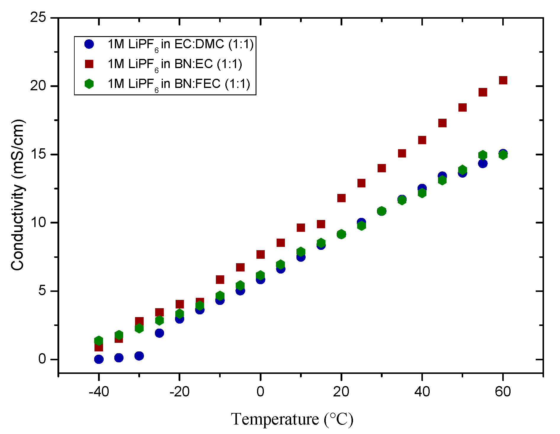
Figure 1. Temperature dependent conductivity measurements of 1M LiPF6 in EC:DMC (1:1), 1M LiPF6 in BN:FEC (1:1) and 1M LiPF6 in BN:EC (1:1), in the temperature range from −40 to 60 °C.
Energies 12 02869 g001
Figure 2. Linear sweep voltammograms of cells containing 1M LiPF6 in BN:FEC (1:1) and 1M LiPF6 in EC:DMC (1:1) (wt.%), LMO as WE, and Li as CE and RE, at scan rate of 100 µV s−1 at room temperature.
Energies 12 02869 g002
Figure 3. Cyclic voltammograms of T44 graphite/lithium cells containing 1M LiPF6 in (a) BN:FEC (1:1), (b) BN:FEC (6:4), (c) BN:FEC (7:3), (d) BN:FEC (8:2), (e) BN:FEC (9:1) and (f) EC:DMC (1:1) as electrolyte formulation, in the potential range between 0.02–2.00 V vs. Li/Li+, at scan rate of 20 µV s−1; insert shows the magnification of the reductive decomposition peak of fluoroethylene carbonate (FEC) at 1.5 V vs. Li/Li+.
Energies 12 02869 g003
Figure 4. C-rate evaluation of the NMC/graphite cells containing (a) 1M LiPF6 in BN:EC (1:1), (b) 1M LiPF6 in BN:EC (7:3) + 1% FEC, (c) 1M LiPF6 in BN:EC (9:1) + 3% FEC and (d) 1M LiPF6 in EC:DMC (1:1) in the voltage range of 3.00–4.30 V.
Energies 12 02869 g004
Figure 5. Cycling profiles and Coulombic efficiencies of the NMC/graphite cells containing 1M LiPF6 in BN:EC (9:1) + 3% FEC and 1M LiPF6 in EC:DMC (1:1) electrolyte formulations cycled in a voltage range of 3.00–4.30 V using a C-rate procedure (a,b) the C-rate of the charge step is increasing while the C-rate of discharge step stays constant at 1C and a C-rate procedure (c,d) where the C-rate of the discharge step is increasing whereas the C-rate of the charge step stays constant at 1C.
Energies 12 02869 g005
Figure 6. Cycling profiles (a) and Coulombic efficiencies (b) of NMC/graphite cells containing 1M LiPF6 in BN:EC (9:1) + 3% FEC as well as 1M LiPF6 in EC:DMC (1:1), respectively as electrolyte, cycled in the voltage range of 3.00–4.30 V.
Energies 12 02869 g006
Figure 7. Long-term cycling profiles of the NMC/T44graphite cells containing electrolyte formulations: (a) 1M LiPF6 in EC:DMC (1:1) without cyclic voltammetry (CV) step (cell a), (b) 1M LiPF6 in EC:DMC (1:1) including CV step (cell b), (c) 1M LiPF6 in BN:EC (9:1) + 3% FEC without CV step (cell c), (d) 1M LiPF6 in BN:EC (9:1) + 3% FEC including CV step (cell d) in the voltage range of 3.00–4.30 V.
Energies 12 02869 g007
Figure 8. F 1s and N 1s core spectra of graphite electrodes, after five charge/discharge cycles at 0.1C in a NMC/graphite cells with different amounts of FEC in the electrolyte: (a,b) 1M LiPF6 in BN, (c,d) 1M LiPF6 in BN + 5% FEC, (e,f) 1M LiPF6 in BN:EC (9:1) + 2% FEC, (g,h), 1M LiPF6 in BN:EC (9:1) + 3% FEC and (i,j) pristine electrode.
Energies 12 02869 g008
Table 1. Summary of solvents used in this work. Physical properties are reported at 25 °C if not stated otherwise [55].
StructureCompoundAbbreviationη(cP)εr
Energies 12 02869 i001Ethylene carbonateEC1.9 a [13]89.8 a [9]
Energies 12 02869 i002Dimethyl carbonateDMC0.59 [56]3.12 [57]
Energies 12 02869 i003Fluoroethylene carbonateFEC4.1 [58]107 [58]
Energies 12 02869 i004ButyronitrileBN0.553 [59]20.7 [60]
a Viscosity (η) and relative permittivity (εr) values for EC are determined at 40 °C.
Table 2. Selected specific discharge capacities for the cells cycled with the BN-based electrolyte (cell a) and 1M LiPF6 in EC:DMC (1:1) (cell b), respectively.
C-RateC-Rate Performance (Charge) Specific Capacity (mAh/g)C-Rate Performance (Discharge) Specific Capacity (mAh/g)C-Rate Performance (Charge/Discharge) Specific Capacity (mAh/g)
Cell aCell bCell aCell bCell aCell b
0.1C176172177174175177
1C152145154149154150
2C144133148139140129
5C125841349910863
10C622368314222
20C92181591
Table 3. 1st Coulombic efficiency, discharge capacity as well as capacity retention between the 10th and 1000th cycle for the reference electrolyte (cells a/b) and the nitrile-based electrolyte formulation (cells c/d) containing cells.
Selected ParametersCell aCell b (CV)Cell cCell d (CV)
(Reference Electrolyte)(Reference Electrolyte)(BN-Based Electrolyte)(BN-Based Electrolyte)
1st Coulombic efficiency (%)87878786
Discharge capacity in the10th cycle (mAh/g)145159155161
Discharge capacity in the 1000th cycle (mAh/g)135139129100
Capacity retention (%)93878362
Table 4. Surface concentration on graphite in arbitrary unit (a.u.) of the performed XPS measurements using different BN-based electrolytes.
Pure BN-Based Electrolyte: Surface Concentration (a.u.)
Sputter time0 s60 s120 s600 s
LIF2.13 (0.25)0.99 (0.71)1.28 (0.05)1.84 (0.66)
N 1 s10.74 (0.98)10.06 (1.24)8.69 (2.07)9.14 (0.38)
BN + 5%FEC based electrolyte: surface concentration (a.u.)
Sputter time0 s60 s120 s600 s
LIF3.80 (1.02)2.14 (2.43)1.26 (0.45)4.00 (0.53)
N 1 s11.83 (0.58)12.26 (0.99)9.37 (0.32)9.78 (0.73)
BN:EC (9:1) + 2%FEC based electrolyte: surface concentration (a.u.)
Sputter time0 s60 s120 s600 s
LIF4.37 (0.79)7.88 (0.22)8.79 (0.28)9.90 (0.16)
N 1 s3.53 (0.35)3.71 (0.28)3.22 (0.11)3.28 (0.21)
BN:EC (9:1) + 3%FEC based electrolyte: surface concentration (a.u.)
Sputter time0 s60 s120 s600 s
LIF12.15 (0.47)16.49 (1.03)18.40 (1.16)20.61 (0.52)
N 1 s0.44 (0.11)0.38 (0.11)0.27 (0.30)0.25 (0.25)
Reference electrode (pristine): surface concentration (a.u.)
Sputter time0 s60 s120 s600 s
LIF0.86 (0.84)2.33 (0.73)1.52 (1.47)1.32 (0.93)
N 1 s0 (0)0 (1.12)0 (0)0 (0)