Article

Analysis of Pouch Performance to Ensure Impact Safety of Lithium-Ion Battery

1
Department of Electronic Engineering, Chonbuk National University, Jeonju 54896, Korea
2
Cell Development team, Samsung SDI CO., LTD., Cheonan 31086, Korea
3
Advances Electronics & Information Research Center, Chonbuk National University, Jeonju 54896, Korea
4
Kunsan National University, Gunsan 54150, Korea
*
Authors to whom correspondence should be addressed.
Energies 2019, 12(15), 2865; https://doi.org/10.3390/en12152865
Submission received: 5 June 2019 / Revised: 17 July 2019 / Accepted: 22 July 2019 / Published: 25 July 2019
(This article belongs to the Section D: Energy Storage and Application)

Abstract

:
The use of mobile devices equipped with embedded batteries is increasing. These embedded batteries are generally lithium-ion batteries in the form of a pouch. However, if an impact is applied to the embedded battery, it can potentially lead to fire and explosion. In this study, we analyzed the safety of the battery, depending on the material and shape of the surrounding pouch. Through tensile strength assessment, an elongation measurement experiment, and impact evaluation, the elements that can improve safety were found. The analysis results confirmed that, as the tensile strength and elongation increased, the impact defect rate decreased. Applying these findings to battery manufacturing can help secure impact safety.

1. Introduction

The use of batteries to supply power to portable equipment is rapidly expanding. In order to reduce the size and weight of such equipment while ensuring long-term capacity, lithium-ion batteries, in particular, are increasingly being used. That is, research into increasing the energy density of a lithium-ion battery with a high voltage is underway. For example, a high-performance battery that meets the above performance has been achieved by increasing the aspect ratio [1,2]. However, as the aspect ratio increases, there are certain safety risks to the battery. It may be vulnerable to dropping, impact, penetration, or fire. In particular, current mobile devices are being released with the battery embedded, as opposed to with a removable battery. In the case of the embedded type of battery, as the battery case is a soft case rather than a hard case, it may be vulnerable to safety problems. Embedded batteries are mainly of the pouch-type.
As the usage of portable devices with these embedded, pouch-type batteries increases, safety issues such as fire and explosion are being raised. The major causes of fire and the explosion of lithium-ion batteries are external shock, external heat, internal short, external short, overcharge, and so on, and the causes of these incidents include battery components and structural or design problems [3,4,5]. In particular, there is a risk of fire or explosion when a consumer impacts a portable device. In order to prevent this, it is necessary to study the impact safety problem of polymer lithium-ion batteries.
Along this research trend, various studies have been conducted in order to secure the safety of the battery. For example, studies have been carried out to improve safety by coating the battery separator [6,7], and studies have also been conducted to improve the performance according to the structural stability of the internal cathode material and the anode material [8,9,10]. In addition, studies have been carried out to improve the safety of the battery by substituting the liquid electrolyte with a polymer electrolyte [11,12], and to secure the capacity and safety by changing the composition of the anode and cathode [13]. Although a variety of studies have been conducted on the materials and compositions of batteries [14,15,16], research on the influence of the external materials on the structural problems and protection of the battery is insufficient.
Therefore, in this paper, we analyze the impact durability according to the physical characteristics of the pouch that surrounds the battery, in order to ensure impact safety. For this purpose, physical performance tests were conducted to analyze the tensile strength, elongation, internal absorption energy, splitting rate, and breaking force of pouches. The impact test was carried out in accordance with the international standard UL1642 [17]. A safety analysis was conducted for each physical element, and the impact safety index and influence parameter of the impact were derived. We also fabricated a battery with the analyzed parameter type, and experimentally assessed the impact safety of the proposed battery.

2. Pouch Type Lithium Ion Battery

In this section, we describe the structure of the pouch-type lithium ion battery applied in this study and describe the material and role of pouch construction in detail.

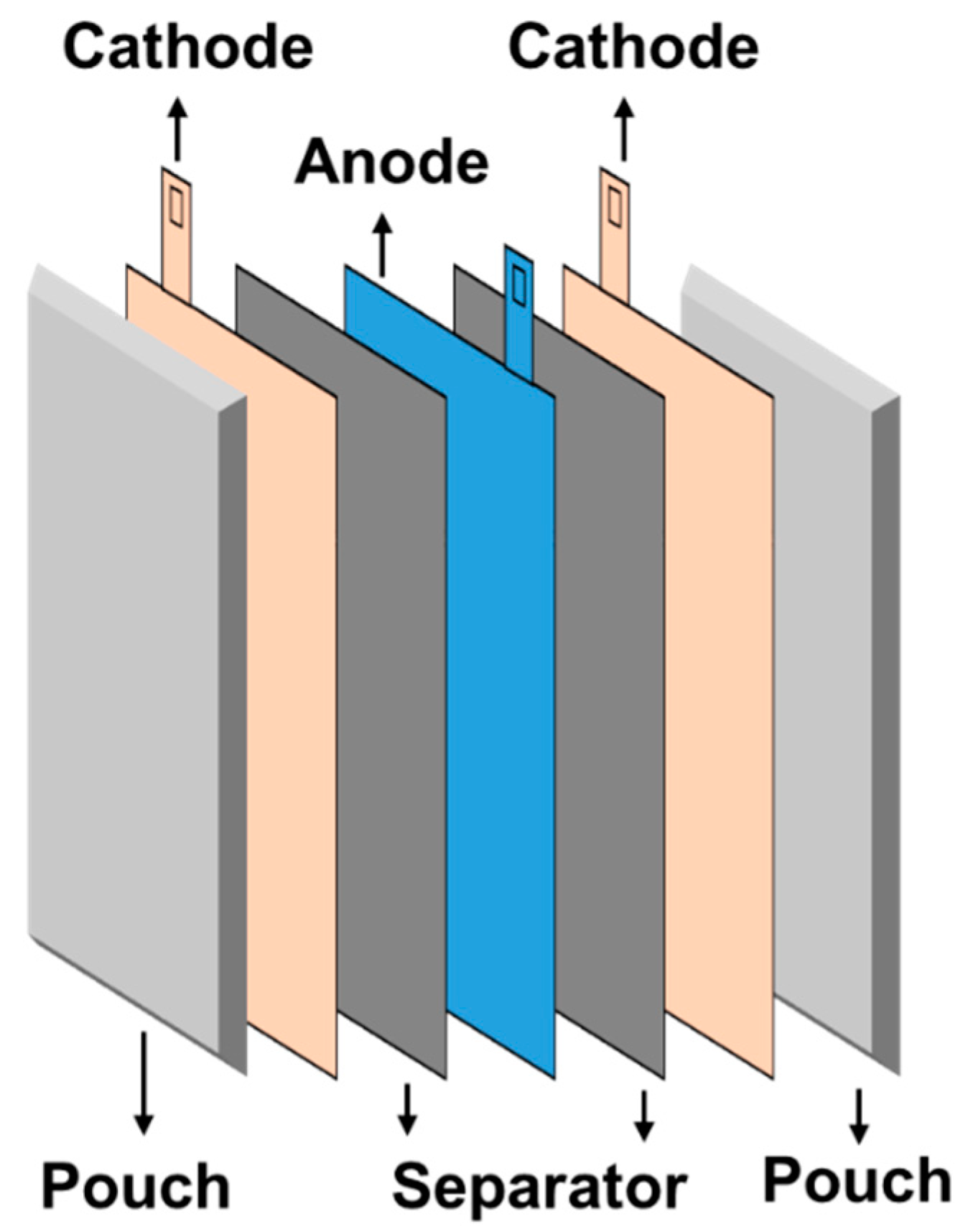
2.1. Pouch-Type Battery Configuration

The pouch-shaped lithium-ion battery is configured as shown in Figure 1. The inside consists of four components, namely: a cathode material, an anode material, an electrolyte, and a separator. The cathode is subjected to a reduction reaction, the anode is subjected to an oxidation reaction, and the separator is located between the two electrodes so as to prevent an electrical short circuit. An electrolyte acting as an ion conductor is also used. In order to protect the internal material, the battery is wrapped in a pouch [18].

2.2. Pouch Material Characteristics

The pouch used for a typical battery consists of five layers, as shown in Figure 2. The outermost base layer (Oriented Nylon) is a material for ensuring formability and insulation. An adhesive with dry lamination is used to maintain the laminate strength between the base layer and the barrier layer. The barrier layer is typically made of aluminum so as to maintain moldability and airtightness. An adhesive layer (S-adhesive or adhesive with polypropylene) is needed in order to maintain the water vapor barrier properties, as well as the adhesion between the barrier layer and the sealant layer. The sealant layer (casting polypropylene (CPP) or polypropylene (PP)) is a layer for maintaining the sealing strength, as well as securing the heat-resistant and insulating property. Based on the barrier layer, the outer layer is composed of biaxially-oriented nylon, while the inner layer is composed of non-elongated CPP or PP [19].

3. Pouch Performance Analysis

In order to analyze the physical performance of the pouch, the tensile strength and elongation were measured. The pouch-type battery was subjected to impact evaluation according to UL1642 [17]. The effects of the measured factors on the battery safety are described as well.

3.1. Tensile Strength and Elongation Measurement

The tensile strength and elongation were measured using a universal testing machine equipped with a crosshead moving at a constant speed, and an upper grip and a lower grip fixing the test specimen. The tensile strength and elongation may vary depending on the preparation method of the test piece, the speed of the test, and the environment [20]. Therefore, these factors must be taken into consideration during the preparation of the test specimen. The specimens should always be prepared in the same way, and samples should be collected from the specimens while avoiding the corrugated or folded parts. In addition, the specimen should be sampled separately from the machine direction (MD) and transverse direction (TD). The size of the specimens should be uniformly determined as a width of 10 cm and a length of 10 cm. When the specimens are prepared, the specimens to be measured should be placed in the upper grip and lower grip of the universal material tester, and then the tensile strength and elongation should be measured based on the maximum load, which can be pulled up until being destroyed. In this study, an AGS-Retrofit universal testing machine from Shimadzu Co. was used.

3.1.1. Tensile Strength Properties

Tensile strength is the maximum load that the specimen can withstand until it is disconnected, divided by the fabric area of the parallel part. If the tensile strength of the pouch is lower than the sealing strength, the pouch on the impact surface has a high possibility of splitting. Yield strength is the stress at which the material will begin to undergo macroscopic plastic deformation. Stress and deformation occur when a load is applied to an object. At this time, the stress is directly proportional to a certain value. Here, the maximum limit at which the direct proportional limit is maintained is called the proportionality limit. In this case, fracture means a plastic or ductile fracture of Al, PE, and so on.

3.1.2. Elongation Properties

The elongation is calculated according to the length of the specimen after the fracture, as measured through the tensile test, as shown in Equation (1).
Percent elongation ( % ) = L x L o L o × 100
where L x is the final gage length and L o is the initial gage length.
If the elongation of the pouch is low, there is a high probability that the pouch will be destroyed in the impact experiment.

3.1.3. Measured Data by Pouch Material

The characteristics of the material constituting the pouch are shown in Table 1. The tensile strength of nylon is the largest, followed, in order, by those of PP, and then Al. Nylon has the largest elongation compared to the other materials. Nylon also has the greatest tensile strength and elongation in the pouch element, which has the greatest effect on the strength of the pouch. MD is machine direction and TD is transverse direction. The sample in the same direction as the direction in which the pouch is made is the MD, while the sample taken in the vertical direction is the TD sample. As the measured values differ according to MD and TD, both experiments were conducted.
Next, the tensile strength and elongation were measured according to the thickness of the pouch. The thickness of the pouch is most related to the thickness of the Oriented Nylon Layer (ONy) layer. That is, the material of ONy is the significant factor. The measurement results are shown in Table 2.
Based on the analysis results, it can be seen that the increased thickness of the pouch leads to a higher tensile strength and elongation. However, as the thickness of the pouch affects the thickness of the battery itself, it is necessary to select an appropriate thickness according to the characteristics of the product. The differences in thickness between pouches A and B are 3 μ m in the ONy layer, and 4   μ m in the Al layer, respectively.

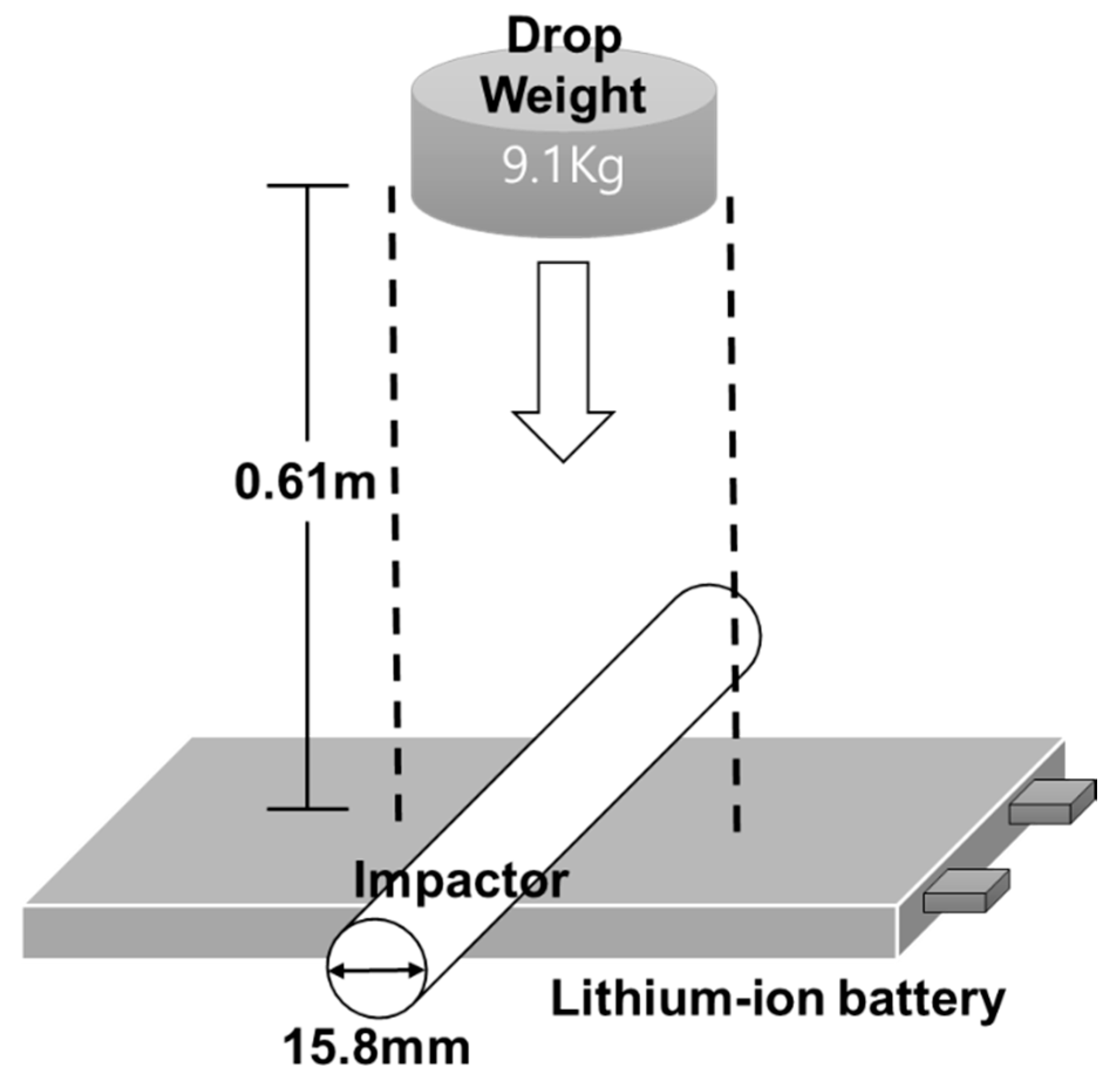
3.2. Impact Evaluation

The impact evaluation was carried out by constructing the system, as shown in Figure 3. First, the impact rod (diameter 15.8 mm) was placed on the lithium-ion secondary battery and dropped with a fall weight (9.1 Kg) at a height of 61 cm, and then the result was measured. The test procedure complies with the international standard UL1642. After the falling weight was dropped free, the surface temperature was observed, and the appearance of the battery was monitored for 10 minutes without fire and explosion. At this time, the Li-ion battery must be in the L0, L1 state in order to be safe for impact, where L0 is a state in which there is no fuming, fire, or explosion, and there is also no electrolyte leakage. L1 is a state in which there is no fuming, fire, or explosion, but an electrolyte leakage occurs.

Impulse and Impulsive Force

The lithium-ion battery receives an impulse and impulsive force when the impact occurs. Assuming that the amount of impulse is the same, the shorter the impact time, the greater the impulsive force. This increases the probability of pouch splitting and increases the probability of heat generation. That is, the rate of impact failure is increased [21].
The impulse, which is the physical quantity representing the degree of impact received by the object, has a magnitude and direction. The magnitude of the impulse ( I ) is calculated as the product of the force ( F ) acting on the object and the time ( Δ t ) acting on the force, as shown in Equation (2).
I = F Δ t ( N s o r k g m / s )
Impulsive force is the force received by an object when it collides. As shown in Equation (3), the magnitude of the impact force is equal to the amount of change ( m Δ v ) in momentum during the unit time ( Δ t ).
F = m Δ v Δ t = m v m v o Δ t
When the impulse amount is the same, the impulsive force becomes smaller as the impact time increases.
The safety of the pouch is determined based on the results of the above experiment. Pouch splitting means that the cell top/bottom is immediately cut and divided into pieces after the impact test. A low probability of pouch splitting indicates that the amount of impulse is reduced. This may lead to a decreased rate of impact failure, where the rate of impact failure means the probability of fire and explosion caused by collision. That is, the pouch should be made to absorb the impulse. It is also important to select the materials accordingly.

3.3. Impact Evaluation and Analysis Results

The variation of the pouch according to tensile strength and elongation is shown in the experiment in Section 3.2. The thicknesses of empty space of pouch A and pouch B are 35 μ m and 36   μ m , respectively. In the case of the pouch B, it is improved by using shrinking ONy. The experimental results are shown in Figure 4. In case A, no thickness deformation occurs in the same way as TD and MD following impact testing. On the other hand, in the case of B, both thicknesses of TD and MD are reduced by about 20%. The above results indicate that, in the case of pouch B, the elongation of the Al base increases and the thickness decreases. In other words, the decrease in thickness means that pouch B is deformed by the external impact and absorbs the external impact. The results of the test confirm that the performance of the pouch was greatly affected by the tensile strength and elongation. Experiments have shown that the tensile strength and elongation should be increased so as to reduce pouch cuts. That is, as the probability that the pouch is completely cut because the impact is lowered, the degree of safety is improved [22,23]. Section 4 shows the results of the experiments obtained using the analysis results.

4. Battery Performance Test According to Pouch Type

In this section, the battery was manufactured and tested based on the results presented in Section 3. The impact test was performed by fabricating a pouch with increased tensile strength and elongation of the pouch so as to be strong against impact. Then, the rate of impact failure was calculated. The experimental battery was designed as shown in Table 3.
The detailed manufacturing specifications are shown in Table 4. Following battery fabrication, the battery is charged at a constant voltage of 4.2 V, at a constant current of 0.5 C and cut-off of 0.05 C.

4.1. Experimental Method

In the collision test, 20 samples were prepared for evaluation, and then a large-sized battery was placed face-up, a collision rod with a diameter of 15.8 mm perpendicular to the longitudinal direction of the battery was placed, and a weight of 9.1 kg was dropped once from a height of 61 cm. Thereafter, the temperature of the battery was maintained until reaching 40 °C or lower, and then the test apparatus was removed and the surface temperature and appearance of the battery were observed for 10 minutes without fire and explosion. During collision testing, the shocked battery may ignite or explode. Therefore, the testing should be carried out in a safe chamber, care must be taken to avoid the risk of fire, and toxic gas may be generated as a result of fire [24].
Figure 5 shows the type of pass or failure. In the above case, the pouch is cut completely, the cut surface comes into contact with the air, and there is a high risk of fire and explosion. In fact, thermal runaway occurred in one cell. In the following cases, as there are few air contact surfaces, the pouch is not cut, and the risk of fire and explosion is low. If it is completely broken, it is considered to be a failure, and vice versa.

4.2. Experiment Result

Three types of pouches were prepared with different thicknesses and tensile strengths. The output and capacity are the same, and the pouches are categorized as C, D, or E, depending on the material used for the pouch. Twenty polymer battery cells with a 4.4 V output and a capacity of 2500 mAh were produced by type. Table 5 shows the characteristics of each cell. Table 6 shows the detailed thickness of each pouch type. The experimental results show that a higher thickness leads to a higher tensile strength and elongation, as well as a lower rate of impact failure. Comparing the C and E yields, a failure rate of 20% difference was observed according to the differences in tensile strength and elongation, according to the internal material used, even when the thickness was the same. Comparing D and E, one can see differences in tensile strength and elongation depending on the thickness, resulting in a failure rate difference of about 40%.
The results confirmed that the tensile strength and elongation were effective factors in securing impact safety. In order to increase the tensile strength and elongation, the thickness of the pouch should be increased. However, if the elongation of the Al layer cannot be secured because of the thickness, collision failure may occur. That is, the ONy layer material, in which the Al layer is capable of absorbing the impulse, must be applied to the pouch.
The E-type pouch uses the shrinkable ONy layer material, and the pouch is confirmed to be superior, in terms of safety, to the other types. It is considered that the adhesion between the pouch layers is improved, and that the tensile strength and elongation are increased. Thus, the elongation of the Al layer was sufficiently secured, and the optimal performance was exhibited in the impact test.
The above results suggest that a pouch-type lithium ion battery that can secure the collision safety of a mobile device equipped with an embedded battery can be designed.

5. Conclusions

In this paper, a method to secure the impact safety of the battery was investigated. In particular, the factors that can secure the safety of the pouch-type lithium-ion battery applied to the embedded battery were analyzed. The rate of impact failure was measured according to the material of the pouch surrounding the battery, and the results differed according to the tensile strength, elongation, and thickness. As the tensile strength and elongation vary depending on the material used in the five layers constituting the pouch, when the tensile strength and elongation at the optimal thickness are secured, the collision safety of the battery may be increased. In this study, the optimal impact safety rate was obtained when the thickness was thicker than 111   μ m , tensile strength was more than 71 N/mm2, and the elongation exceeded 45%.
In future research, we intend to carry out a study to secure the impact safety according to the influence of the internal material of the battery.

Author Contributions

The individual contributions of authors are as follows. S.Y. developed analysis methods and wrote the paper. The analysis and performance discussion were performed by C.H. and K.T.C. and N.S. directed the research and contributed to the refinement of the methods.

Funding

This research was funded by the Korean government (MSIT) grant number No. NRF-2017M3C7A1044815.

Acknowledgments

This research was supported by the Brain Research Program of the National Research Foundation (NRF) funded by the Korean government (MSIT) (No. NRF-2017M3C7A1044815).

Conflicts of Interest

The authors declare no conflicts of interest.

References

  1. Larsson, F.; Andersson, P.; Mellander, B.E. Lithium-ion battery aspects on fires in electrified vehicles on the basis of experimental abuse tests. Batteries 2016, 2, 9. [Google Scholar] [CrossRef]
  2. Choi, J.W.; Aurbach, D. Promise and reality of post-lithium-ion batteries with high energy densities. Nat. Rev. Mater. 2016, 1, 16013. [Google Scholar] [CrossRef]
  3. Zhang, J.; Zhang, L.; Sun, F.; Wang, Z. An Overview on Thermal Safety Issues of Lithium-ion Batteries for Electric Vehicle Application. IEEE Access 2018, 6, 23848–23863. [Google Scholar] [CrossRef]
  4. Balakrishnan, P.G.; Ramesh, R.; Kumar, T.P. Safety mechanisms in lithium-ion batteries. J. Power Sources 2006, 155, 401–414. [Google Scholar] [CrossRef]
  5. Wen, J.W.; Yu, Y.; Chen, C.H. A review on lithium-ion batteries safety issues: Existing problems and possible solutions. Mater. Express 2012, 2, 197–212. [Google Scholar] [CrossRef]
  6. Lee, Y.M.; Lee, C.H. Separators for Li-ion Secondary Batteries. Membr. J. 2004, 14, 263–274. [Google Scholar]
  7. Wang, Z.; Sang, L.; Liu, Z.; Chen, Q. The modification of Lithium ion battery separator by SiOx coatings. In Proceedings of the IEEE International Conference on Plasma Science, Edinburgh, UK, 8–13 July 2012. [Google Scholar]
  8. Lee, Y.K. The Effect of Active Material, Conductive Additives, and Binder in a Cathode Composite Electrode on Battery Performance. Energies 2019, 12, 658. [Google Scholar] [CrossRef]
  9. Liu, K.; Pei, A.; Lee, H.R.; Kong, B.; Liu, N.; Lin, D.; Liu, Y.; Liu, C.; Hsu, P.-C.; Bao, Y.Z.; et al. Lithium metal anodes with an adaptive “solid liquid” interfacial protective layer. J. Am. Chem. Soc. 2017, 139, 4815–4820. [Google Scholar] [CrossRef] [PubMed]
  10. Li, N.-W.; Yin, Y.-X.; Yang, C.-P.; Guo, Y.-G. An artificial solid electrolyte interphase layer for stable lithium metal anodes. Adv. Mater. 2016, 28, 1853–1858. [Google Scholar] [CrossRef] [PubMed]
  11. Zhang, S. Improved Cyclability of Liquid Electrolyte Lithium/Sulfur Batteries by Optimizing Electrolyte/Sulfur Ratio. Energies 2012, 5, 5190–5197. [Google Scholar] [CrossRef]
  12. Zhang, S.S. A review on electrolyte additives for lithium-ion batteries. J. Power Sources 2006, 162, 1379–1394. [Google Scholar] [CrossRef]
  13. Aurbach, D.; Gamolsky, K.; Markovsky, B.; Gofer, Y.; Schmidt, M.; Heider, U. On the use of vinylene carbonate (VC) as an additive to electrolyte solutions for Li-ion batteries. Electrochim. Acta 2002, 47, 1423–1439. [Google Scholar] [CrossRef]
  14. Hess, S.; Wohlfahrt-Mehrens, M.; Wachtler, M. Flammability of Li-ion battery electrolytes: Flash point and self-extinguishing time measurements. J. Electrochem. Soc. 2015, 162, A3084–A3097. [Google Scholar] [CrossRef]
  15. Dudney, N.J. Addition of a thin-film inorganic solid electrolyte (Lipon) as a protective film in lithium batteries with a liquid electrolyte. J. Power Sources 2000, 89, 176–179. [Google Scholar] [CrossRef]
  16. Doughty, D.H.; Roth, E.P. A general discussion of Li ion battery safety. Electrochem. Soc. Interface 2012, 21, 37–44. [Google Scholar] [CrossRef]
  17. Underwriters Laboratories. UL Standard for Safety for Lithium Batteries, 4th ed.; (UL 1642); Underwriters Laboratories Inc.: Northbrook, IL, USA; p. 2007.
  18. Reddy, T.B. Linden’s Handbook of Batteries, 4th ed.; McGraw-Hill companies Inc.: New York, NY, USA, 2010. [Google Scholar]
  19. Daniel, C.; Besenhard, J.O. Handbook of Battery Materials, 2nd ed.; Wiley-VCH Verlag, GmbH & Co. KGaA: Weinheim, Germany, 2011. [Google Scholar]
  20. International Organization for Standardization. Metallic Materials-Tensile Testing at Ambient Temperature (ISO 6892); International Organization for Standardization: Geneva, Switzerland, 1998. [Google Scholar]
  21. Gisberg, J. Engineering Dynamics; Cambridge University Press: New York, NY, USA, 2007. [Google Scholar]
  22. Wang, Q.; Ping, P.; Zhao, X.; Chu, G.; Sun, J.; Chen, C. Thermal runaway caused fire and explosion of lithium ion battery. J. Power Sources 2012, 208, 210–224. [Google Scholar] [CrossRef]
  23. Bandhauer, T.M.; Garimella, S.; Fuller, T.F. A critical review of thermal issues in lithium-ion batteries. J. Electrochem. Soc. 2011, 158, R1–R25. [Google Scholar] [CrossRef]
  24. Ashok, L.; Nirav, S.; Cameron, D. Building a safer, denser lithium-ion battery. IEEE Spectr. 2018, 55, 34–39. [Google Scholar]
Figure 1. Structure of a pouch-type lithium-ion battery.
Energies 12 02865 g001
Figure 2. Pouch component.
Energies 12 02865 g002
Figure 3. Schematic diagram of the impact test.
Energies 12 02865 g003
Figure 4. Schematic diagram of the impact test. Here, the space between the outer layer and inner layer is an empty space of the pouch formed in the form of a jellyroll. The empty space of pouch A remained constant because of the lower elongation rate, and the empty space of pouch B was reduced because of the high elongation rate. In other words, pouch B absorbed the impact.
Energies 12 02865 g004
Figure 5. Impact test results. These are examples of failure and pass. Failure means being split completely.
Energies 12 02865 g005
Table 1. Characteristic of materials. PP—polypropylene; MD—machine direction; TD—transverse direction.
ItemUnitDirectionOriented
Nylon
AluminumAdhesivePP
80218079
Densityg/cm2-1.152.732.720.90.9
Melting point°C-220650660160140
TensileTensile strengthMPa
(N/mm2)
MD2509575--
TD280
Tensile stretch Rates%MD1301710--
TD110
Table 2. Pouch tensile strength according to thickness.
Sample Width (4 mm)Tensile Strength (MD)Elongation
(MD)
Tensile Strength (TD)Elongation
(TD)
Thickness
( μ m )
PouchNN/mm2%NN/mm2%
68A17.864.532.921.076.467.5
75B23.886.784.118.667.831.9
B/A134%134%256%89%89%47%
Table 3. Battery design specification.
ItemCathodeAnode
Initial charge capacity153 mAh/g386 mAh/g
Initial discharge capacity146 mAh/g361 mAh/g
efficiency96.2%93.76%
Current density3.48 ± 0.2 mA/cm2
Loading level24.1 ± 0.5 mg/cm210.2 ± 0.5 mg/cm2
Electrode density3.45 g/cc1.62 g/cc
NP/Ratio1.13
Table 4. Details of the battery manufacturing items.
ClassificationItemContents
CathodeCathode electrodeCathode materialLiCO2, 95 wt%
Conductive materialSuper P, 2 wt%
BinderPVDF, 3 wt%
Solid Content74.35%
Loading quantity47.01 mg/cm2
(A side: 23.52 mg/cm2; B side: 23.49 mg/cm2)
Electrode density
(after roll pressing)
3.45 g/cc
Electrode thickness147 ± 3 μ m
Cathode foil
(Aluminum-foil)
Thickness15 μ m
Weight4.10 mg/cm2
AnodeAnode electrodeAnode materialNatural graphite (DAG-E1), 97.6 wt%
BinderSBR (Zeon-BM400B), 1.4 wt%
Carboxymethyl Cellulose
(CMC)
Daitchi SBH-12, 1.0 wt%
Solid Content53.3%
Loading quantity19.61 mg/cm2
(A side: 9.85 mg/cm2; B side: 9.76 mg/cm2)
Electrode density
(after roll pressing)
1.62 g/cc
Electrode thickness131 ± 3 μ m
Anode foil
(Copper-foil)
Thickness8 μ m
Weight7.64 mg/cm2
ElectrolyteLithium saltLiPF6, 1 Mole
SolventEC:EMC:DMC = 3:4:3
additiveVC, 3 wt%
Amount of input2.50 ± 0.04 g
Pre-chargingCapacity130 mA
Table 5. Impact test result of a 4.4 V, 2500 mAh cell.
Type Thickness   ( μ m ) Tensile Strength
(MD) (N/mm2)
Elongation
(MD)
(%)
Tensile Strength
(TD) (N/mm2)
Elongation
(TD)
(%)
Impact Failure Rate (%)
C11163.7430.4876.0241.9820
D8660.7238.2358.3836.2040
E11171.2144.9776.7775.460
Table 6. Thickness of each layer according to pouch type.
TypePouch Components
ONy   ( μ m ) DL   ( μ m ) Al   ( μ m ) SA   ( μ m ) CPP( μ m )Total( μ m )
C20340345111
D1533533086
E25340340111

