1. Introduction
Concentrated solar thermal technologies are interesting renewable energy systems to be incorporated in industrial heat processes [
1]. There are two main technologies that fit in the range of temperature demanded by several industrial processes, i.e., parabolic-through collector (PTC) and linear Fresnel reflector (LFR) [
2].
In the last four decades, in terms of concentrated solar power plants, PTC has been leading the energy production and the number of facilities installed over LFR [
3]. From an optical point of view, a PTC has a higher optical performance compared to a LFR, explained by the transversal component of the beam solar radiation impinging on the LFRs reflectors aperture, which decreases the optical efficiency of the collector. However, LFR has a simpler concept related to the absence of metal-glass welds in the receiver tubes, commonly present in the receivers for PTCs, and they do not require flexible hoses or ball joints between adjacent collectors. Also, the use of land is more efficient with LFRs because shadows between neighboring collectors are reduced. Finally, the optical components of LFR are cheaper due to the nearly flat shape of the mirrors. All these advantages result in lower operational and investment costs [
4,
5]. As a consequence, all these aspects lead to a technology as attractive as PTC technology. LFR has a significant development potential that explains the current research efforts on this solar collector technology.
A LFR system consists of an array of slightly curved reflectors composing the optical solar concentrator and a receiver, which is fixed and collects the solar energy concentrated by the primary reflectors. These reflectors need to track the sun throughout daytime in order to reflect the incoming solar rays to the receiver position. The receiver may be composed of one single tube or a group of parallel tubes, located horizontally above the reflectors plane.
To ensure low investment costs, it is important to design as efficient components as possible. For example, a way to achieve this is using a less amount of material but maintaining the durability and performance requirements of the components. This work is focused on a manufacturing procedure of facets for LFR’s primary reflectors. Each step of the procedure defined is detailed, altogether with different assembly possibilities that have been tested.
2. Background on LFR Mirrors Geometry
LFR works as an optical concentrator, which means that the mirror facets that compose the primary reflector, concentrate the solar rays in the receiver. As explained in
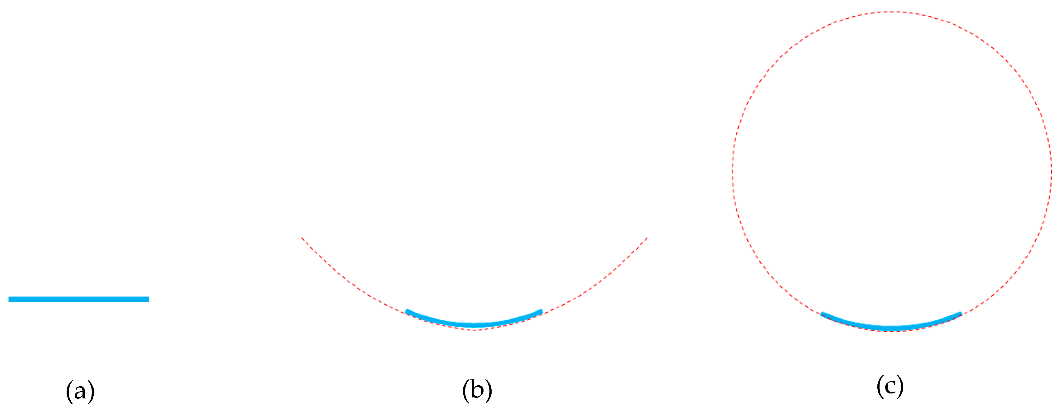
Section 1, the primary reflector is the component where the concentration takes place. The shape of the mirrors that form the reflector is essential to the concentration rate that the collector reaches. The geometrical shape of the mirrors is defined from their transversal profile; the shapes addressed in this work are flat, parabolic and cylindrical (
Figure 1).
2.1. Flat Mirrors
Flat-shaped mirrors (
Figure 1a) are the simplest configuration; in this case, the transversal mirror profile is a straight line. From the optical point of view, the width of the image reflected by a flat-shaped mirror is practically the same as the mirror’s actual width. The setback of flat-shaped mirrors is that one single mirror does not concentrate the radiation by itself, because the area of reflection is the same as the area of the reflected image. The concentration takes part when the reflected image of a group of mirrors is directed to the same place. Another disadvantage related to the use of flat-shaped mirrors is that the width of the mirrors must be virtually the same as the width of the receiver, because if the mirrors were wider, some of the reflected rays would not hit the receiver (overflow effect). For this reason, the width of flat-shaped mirrors and receivers are restricted to each other.
2.2. Parabolic Mirrors
Parabolic geometry (
Figure 1b) perfectly fits with optical concentration technologies, because, by definition, the rays impinging perpendicularly to the aperture are reflected into the focal point of the parabola. In the case of solar collectors with parabolic reflectors, this condition is achieved when the reflectors track the movement of the sun during daytime. According to this geometrical principle, PTCs and LFRs have been using parabolic mirrors since the beginning of their operations [
3,
6].
Particularly in the LFR technology, from the construction point of view, to achieve a parabolic profile in the transversal section of the mirror is a difficult task to accomplish compared to other options. One option is to manufacture the mirror directly with the desired shape. However, this option is discarded because it limits the availability of suppliers and implies higher costs. An alternative option consists on assembling mechanically a straight mirror into a preformed pattern with the desired parabolic profile. In order to achieve this assemblage and to adopt the desired shape, the mirrors must be as thin as possible. This pattern could be a solid plate or a group of profiles named “ribs”. Both possibilities require the material to be previously manufactured into the desired shape. The result is optimal optical behavior of the primary reflector. However, economically, the cost of manufacturing the pattern is higher compared to other geometries.
2.3. Cylindrical Mirrors
From the geometrical point of view, cylindrical mirrors (
Figure 1c) are not as accurate as parabolic mirrors, but constructively, they are easier and cheaper to manufacture. With this geometry, the concentration of the rays is achieved when the distance from the mirror to the receiver is considerably larger than the width of the mirror [
7].
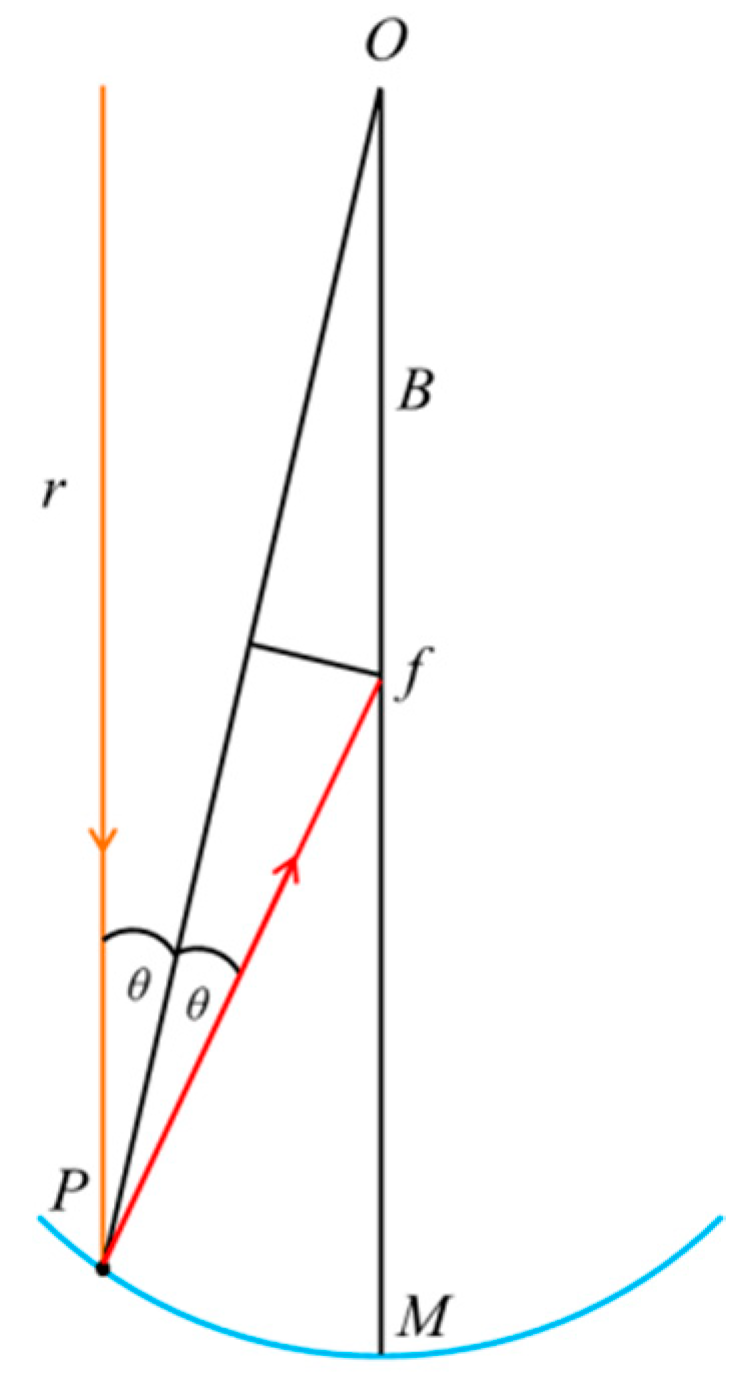
In
Figure 2, the scheme shows a cylindrical mirror, which is a segment of a circumference, and a ray,
r, impinging perpendicularly to the aperture of the mirror in a point
P. The ray is reflected and directed to
f. The angles formed by the reflected ray and the incidence angle,
θ, which are angles referring to the normal vector of the mirror, are equal according to specular reflection laws [
8]. The point
f is at a distance
B from the center
O of the circumference. The distance between the points
O and
M is the radius of the circumference that contains the cylindrical mirror.
The points
P,
f and
O form an isosceles triangle, with
θ in both equal angles. This triangle can be divided into two right triangles. The relation between the distances
B, the radius
R of the circumference that contains the mirror, and the angle of incidence/reflection
θ is given by:
As previously said, the condition to accomplish the concentration of the rays for a cylindrical geometry requires the width of the mirror to be smaller than the distance to the receiver. The former leads to a small value of the angle θ, then cos θ ≈ 1. Therefore, the rays impinge into the middle of the circumference radius, B = R/2. This position is where the receiver of the LFR is placed.
As consequence, the mirror takes the form of a segment of a circumference with a radius two times larger than the focal distance, i.e., the distance from the mirror to the receiver.
From an optical point of view, every mirror has a singular focal distance to the receiver, which leads to a different radius of curvature for each mirror. Manufacturing different preformed patterns with every radius of curvature would increase the cost of the LFR.
3. Materials and Methods
3.1. Definition of Mirrors Geometry
From the different options presented in
Section 2, it is initially stated that the cylindrical geometry can lead to an adequate solution in terms of cost and performance for a medium-size LFR and is comparable in performance to the parabolic shape.
For the definition of the mirror’s geometry, an iteration process is performed using a previously created in-house ray trace code [
9]. The goal of the process is to maximize the power impinging on the receiver while using one single radius of curvature for all mirrors (cylindrical shape). At each iteration, a specific radius of curvature is employed for all mirrors, which is changing from the focal distance of the farthest mirror from the receiver to the focal distance of the nearest one. As result of the application of this procedure, it is established that the radius of curvature of the farthest mirror delivers the best results. In addition, it is concluded that the optical performance when the farthest radius is used, is rather similar to the performance of a configuration that involves a particular and theoretician radius for every mirror (the average decrease estimated is 2%).
In order to endorse the optical behavior of cylindrical mirrors compared with parabolic mirrors, a new set of simulations are carried out. First, cylindrical mirrors are considered in the model and the power impinging on the receiver is obtained. Then, parabolic mirrors replace the cylindrical mirrors under the same conditions of the previous simulation. The results show that the optical behavior is rather similar for both configurations. As a consequence, it is stated that the optical handicap of using cylindrical mirrors instead of parabolic mirrors is marginal [
9].
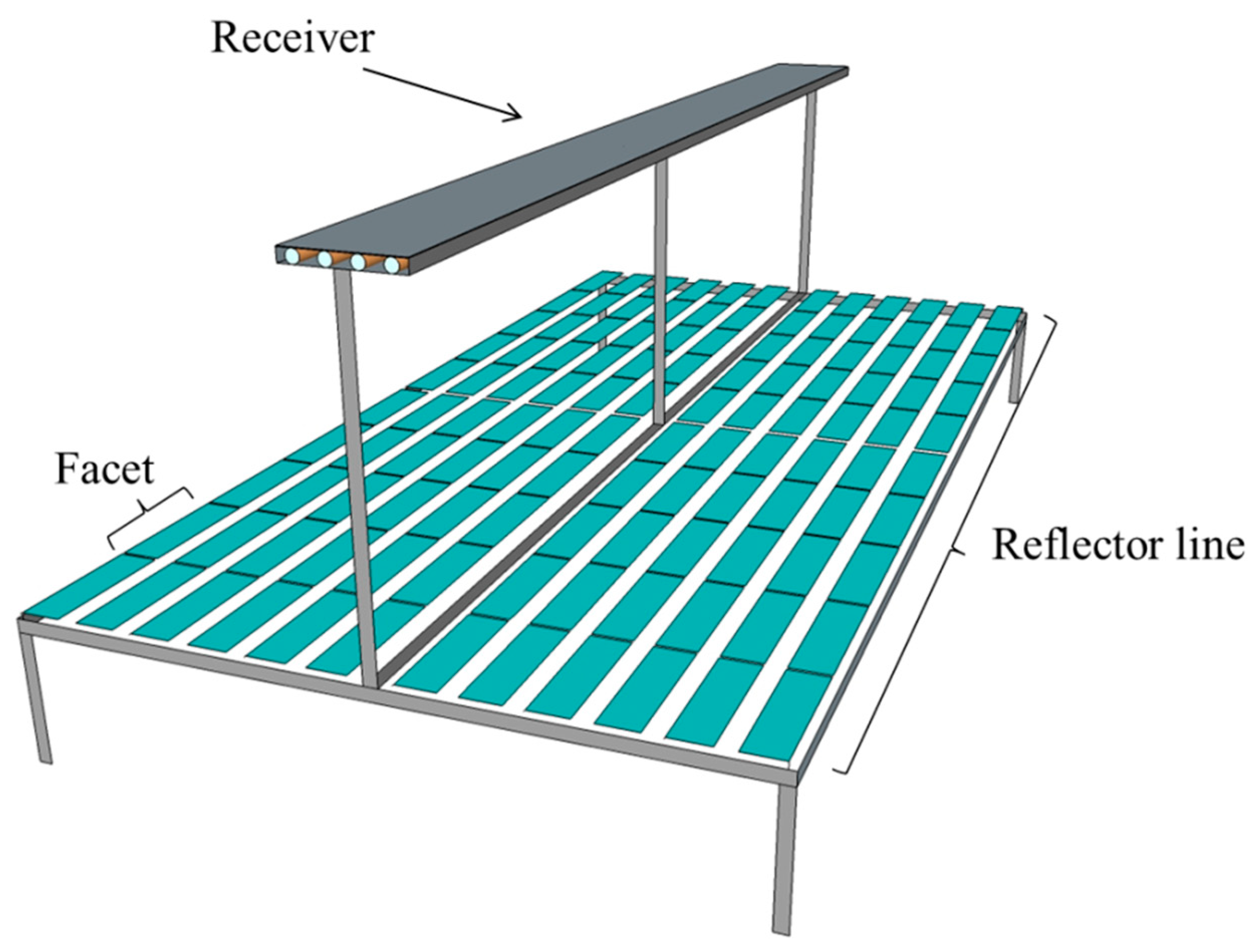
The LFR considered in this study is composed of 12 lines of reflectors, 10-m-long and 28-cm-width. Every 10 m line is divided into 10 facets, 1-m-long each (
Figure 3). The procedure and analysis described from now on is related to a 1-m-long and 28-cm-width single facet.
The weight of the facets in the mechanical behavior of the collector is absolutely relevant. The goal is to accomplish a facet as light as possible, decreasing the load on the engine used for the movement of the whole reflectors’ line to track the Sun. The maximum weight of one facet is set at 4 kg. The facets are assembled from two main components, the mirror and the structure that holds and shapes the mirror into the cylindrical geometry. Regardless of the type of structure and according to the weight restriction imposed, the material used is a 3-mm-thick metallic plate resistant to outdoor conditions. As explained, due to cost saving, the mirror does not have a pre-shaped geometry, and so the mirrors should be as thin as possible in order to properly adopt the geometry imposed by the structure. The mirror used is a 1-mm-thick highly-reflective glass-silvered mirror. Considering the characteristics of the materials selected, it is stablished that the maximum permissible geometrical deviation of the facets should be 0.5 mm from the sag parameter, which is defined in
Section 4.
3.2. Mirrors Structure Configuration
Different configurations of the structure that support and shape the mirror into the facet are considered in this study, taking as premises the simplicity and the economy of the approaches without losing sight of the optical performance. The following subsections describe each configuration.
3.2.1. Naked Mirror over Preformed Ribs
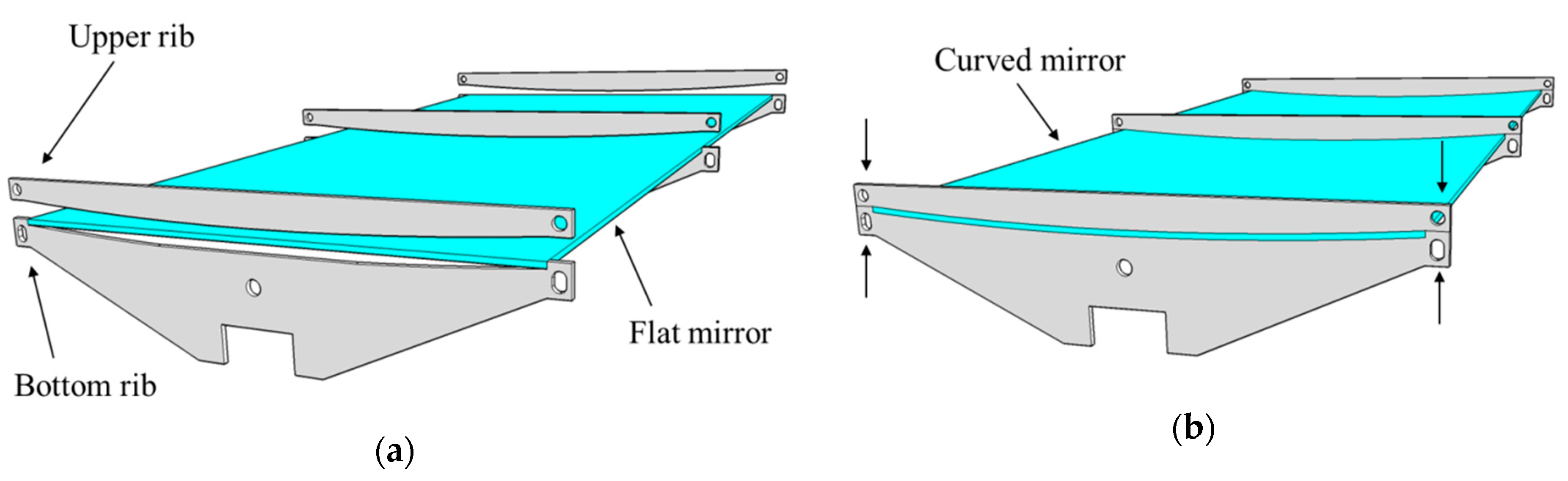
The first approach to manufacture the facet’s support structure is to mechanically bend the mirror in a cylindrical shape by clamping it between a set of preformed “ribs”. Each rib is composed of two aluminum pieces (
Figure 4a), the bottom piece that supports the mirror has a concave cylindrical geometry and the upper part, pushing down the mirror, has a convex cylindrical shape (
Figure 4b). The bottom part of the ribs should also work as a union among three pairs of ribs that are used per individual facet, and to join to the others facets composing one of the 10-m-long reflectors’ lines of the collector.
3.2.2. Naked Mirror Mechanically Bended by Metallic Bars Glued to it
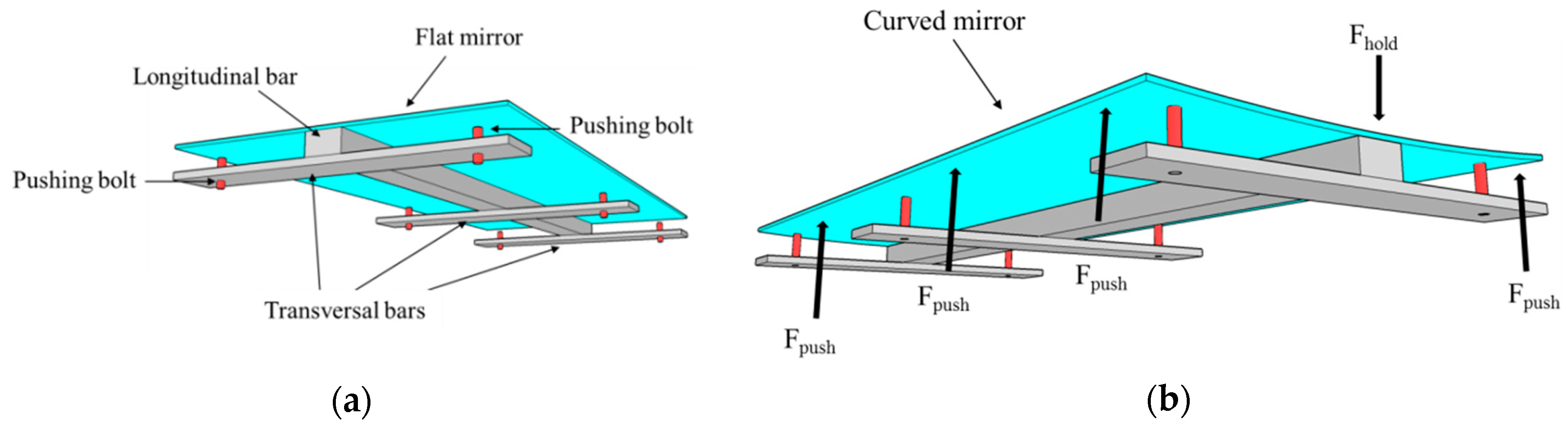
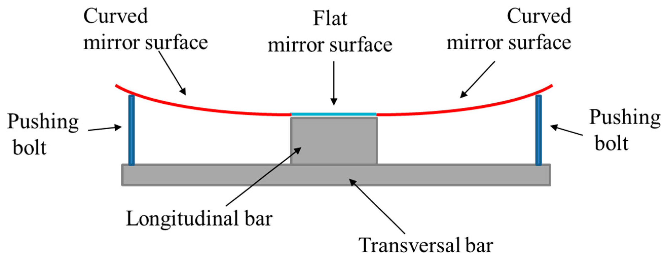
This configuration uses a different approach to bend the mirror into a cylindrical shape. First of all, an aluminum bar is glued to the middle of the longitudinal axis of the mirror with structural silicone. Later, three transversal bars are fixed to the longitudinal bar (
Figure 5a). In each extreme of the transversal bar, a pushing bolt (marked in red in
Figure 5a) is installed. With this bolt, both sides of the mirror can be pushed and raised to achieve the desired shape, while the center of the mirror stays down, attached to the longitudinal bar. The result is a curved mirror created by two equal and opposite forces (See F
push and F
hold in
Figure 5b).
3.2.3. Mirror Glued by Vacuum over a Curved Rectangular Plate Attached to a set of Preformed Ribs
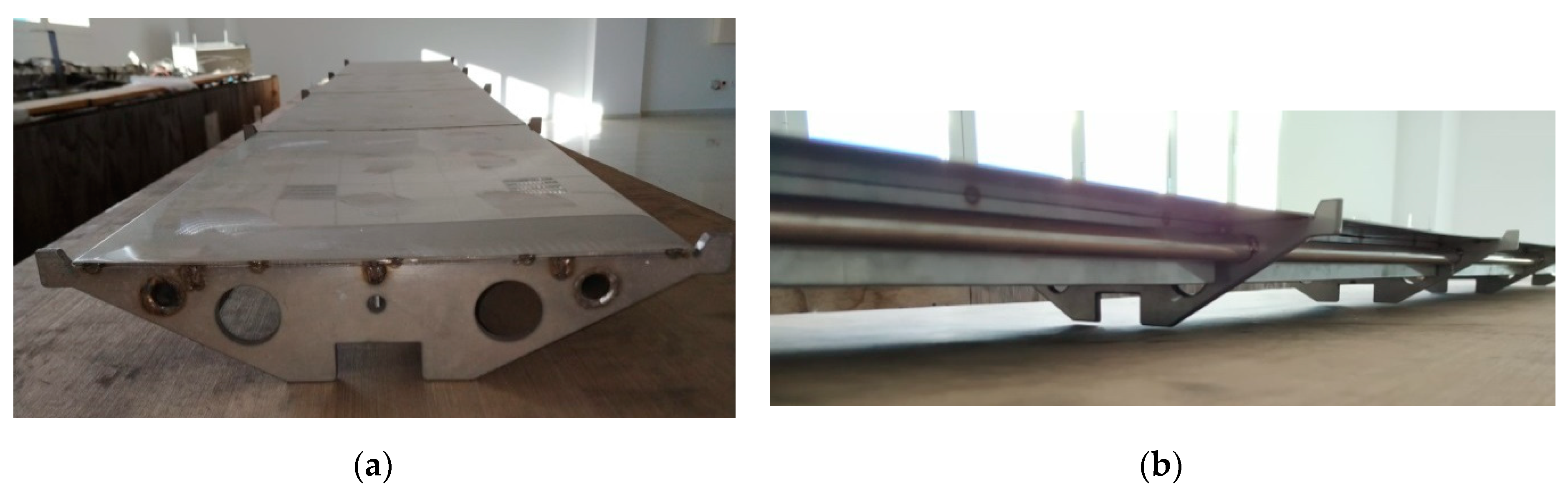
Unlike the two former assemblies, the objective of this third configuration is to deliver a solid structure to support the mirror over its entire surface (
Figure 6a). A pre-formed rectangular thin plate, made of 3-mm-thick stainless steel, is considered. This plate has the same dimension as the mirror and makes up the cylindrical shape of the facet. This curved plate is welded to a group of stainless steel ribs that provide the needed stiffness to keep the cylindrical shape. The ribs are aligned in a longitudinal direction by two metallic tubes welded to them (
Figure 6b). The selection of steel as a constructive material instead of aluminum is due to the difficulty of welding the aluminum plate to the ribs. Due to the high thermal diffusivity of the aluminum, during the welding process, the whole piece could be heated, which along with the small thickness of the plate might entail the deformation of the plate when the material is chilling.
In
Figure 6, the configuration of the proposed assembly is shown. The flat mirror is located over the curved plate; previously, an adhesive is sprayed over the back face of the mirror and on the upper face of the metallic plate. Once the mirror and plate are joined, the assembly is introduced into a plastic bag to complete the sealing process. A vacuum pump is connected to an air outlet valve of the plastic bag to evacuate the air inside the bag, reducing the possibility of bubbles appearing between the mirror and the metal plate. This gluing process takes 15 minutes approximately. After this time, both the mirror and the metallic plate should be completely attached, with the mirror adopting the cylindrical shape of the plate.
3.2.4. Mirror Glued by Vacuum to a Curved Plate
The idea of gluing the mirror to a preformed plate used in the former configuration (
Section 3.2.3) is considered as a useful solution to build facets for LFR. The mechanism of completing the gluing process in vacuum delivers optimal results. The challenge is to minimize the weight of the assembly described in
Section 3.2.3; therefore, the first action is to replace the steel plate by another type of plate made of a material with lower density, e.g., aluminum.
The curvature of the plate must be achieved as accurately and repetitively as possible. The process selected to achieve the desired geometry consists of inserting the flat rectangular plate into a bending machine. The bending machine used in the experimental set up is made up of three longitudinal cylinders; first, the user adapts the position of two of the three cylinders to the thickness of the processed plate and, second, the third cylinder is moved up and down until the desired curvature of the structural plate is achieved. Once the positions of the cylinders are settled, the metallic plate is introduced and automatically curved.
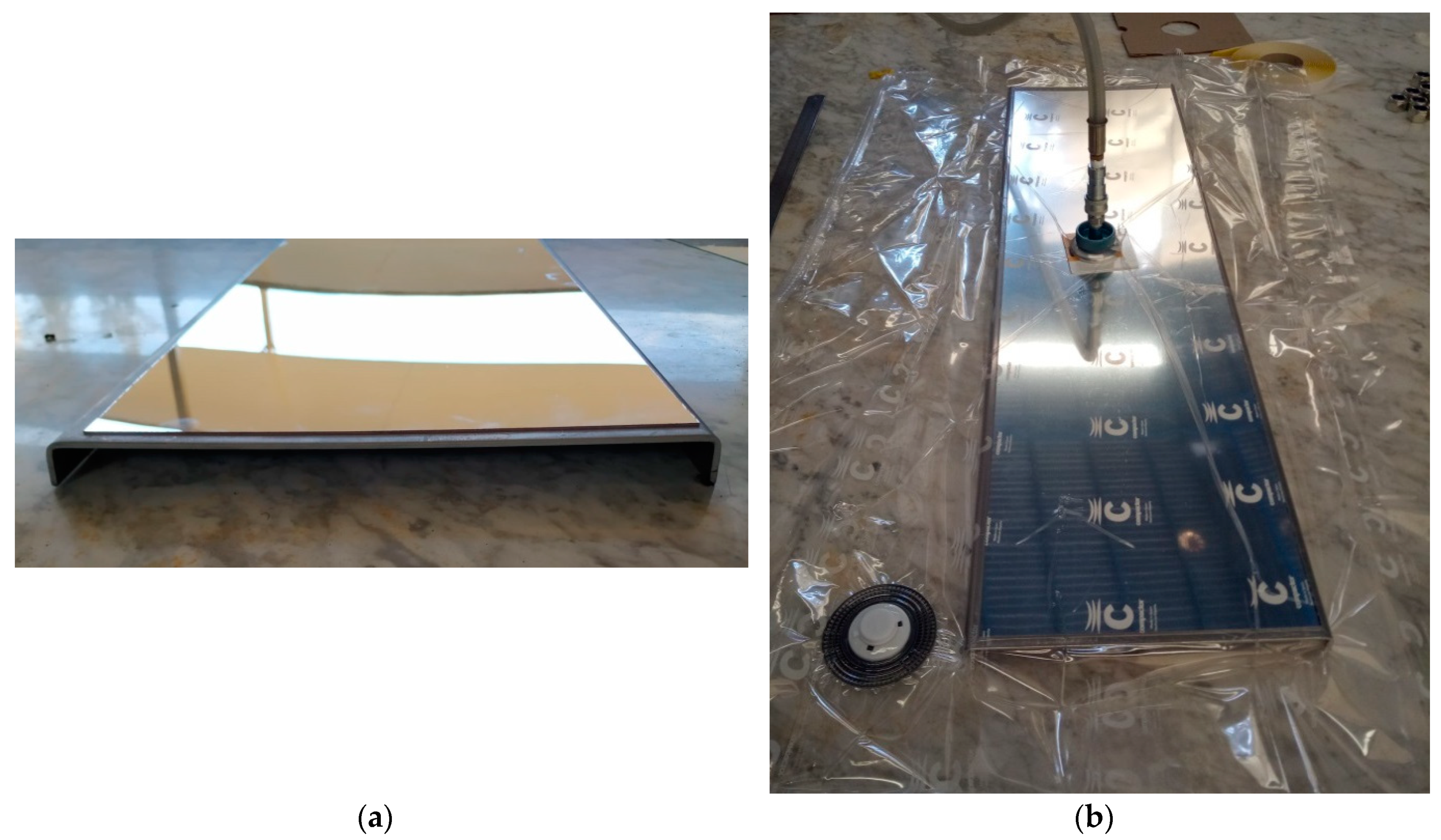
The next step is to provide rigidity to the curved plate, which is done, for this specific facet size, by pleating 1.5 cm of the longitudinal extreme of the plate (
Figure 7a). This pleat gives the plate enough stiffness in the longitudinal axis to avoid the plate losing linearity.
Once the plate is curved and pleated, the mirror is glued to the metallic plate following the same procedure explained in
Section 3.2.3. The glue is sprayed onto the mirror and the plate, and then the set is put in a plastic bag, sealed and connected to a vacuum pump (
Figure 7b).
At this point, the reflective part of the facet is completed, but as shown in
Figure 7a, there are no structural bars or other elements in the aluminum plate to connect the facet neither to the LFR’s main structure nor to the other facets. The welding of structural bars to the aluminum plate is not an adequate solution, as explained in
Section 3.2.3. The solution proposed and designed is a suction cups system attached with silicone to the back face of the aluminum plate. These cups attach the facet to a structural bar, altogether with every one of the other nine facets conforming one 10-m-long line of 12 mirrors that compose the primary concentrator of the LFR collector.
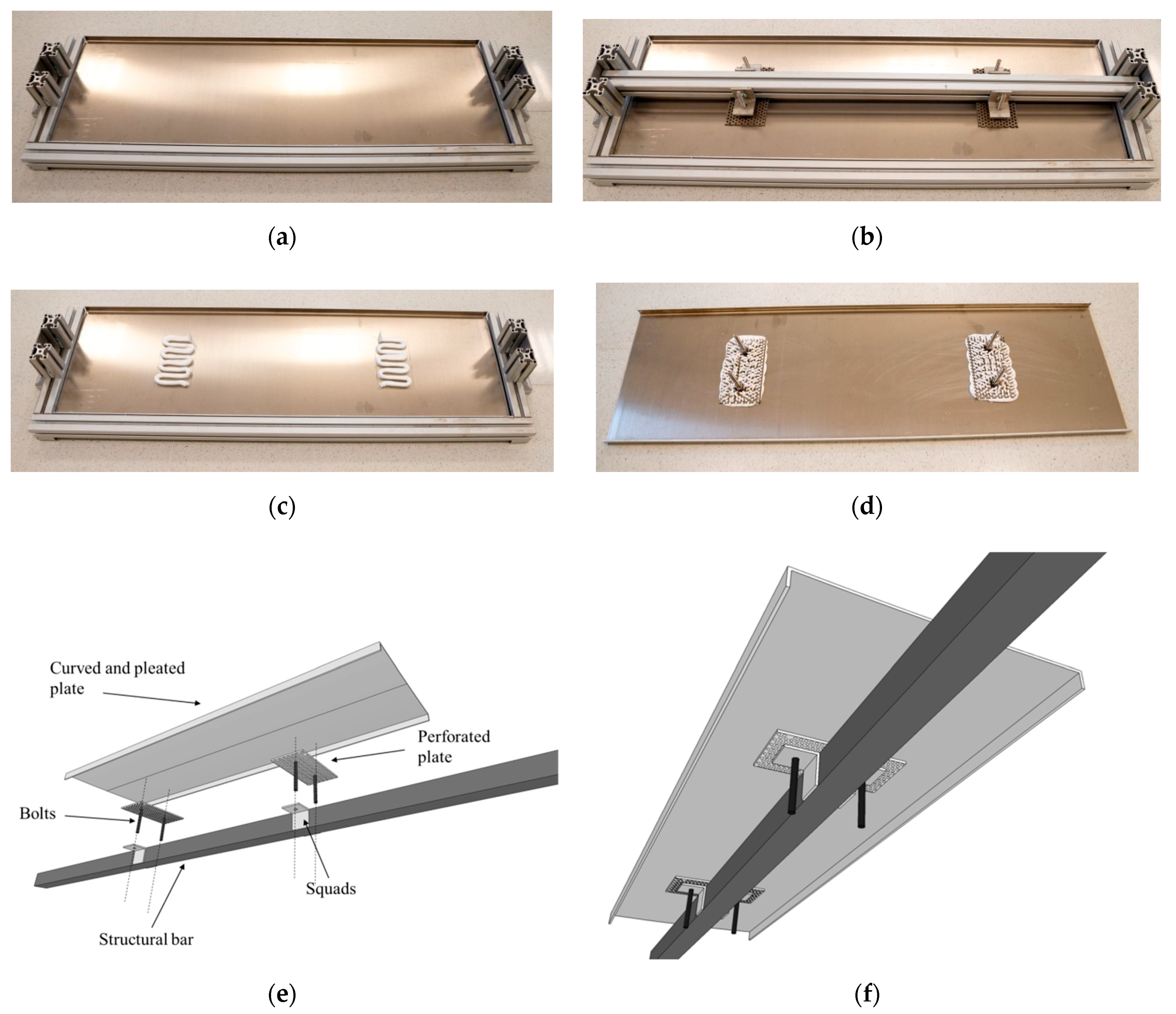
The suction cups are composed by a perforated 3-mm-thick plate and two bolts welded to this plate. The perforations of the plate are designed to allow the silicone to overflow through it. The structural bar fit to the suction cup by two welded segments profiles type “L”. These squads have a perforation in which the bolt fits and is adjusted with a pair of nuts (
Figure 8e,f).
The complete assembly process of the suction cups into a mirror facet is shown in
Figure 8. First, the facet (which has already been curved, pleated and the mirrors glued to it) is faced down into an alignment device (
Figure 8a). This object is designed to line up the suction cups between them and with the facet. A longitudinal bar, which fits in the frame of the alignment device, is used to place the suction cups in the desired position on the facet (
Figure 8b). The suction cups are held to the bar through a pair of squads. Once the position of the suction cup on the back side of the facet is defined, the bar is removed and a thick silicone cordon is applied on the back side of the plate (
Figure 8c). Finally, the suction cups are placed again with the bar pressing down strongly until the silicone overflows through the perforations of the plate (
Figure 8d).
4. Results
This section details the results obtained during the manufacturing process of facets assembled following the four procedures presented in
Section 3 for the mirrors structure configuration. The geometrical quality of mirror facets manufactured following the manufacturing process that delivers the best results is also analyzed.
4.1. Naked Mirror over Preformed Ribs
The image reflected by this facet does not have the quality required to concentrate the rays on the receiver.
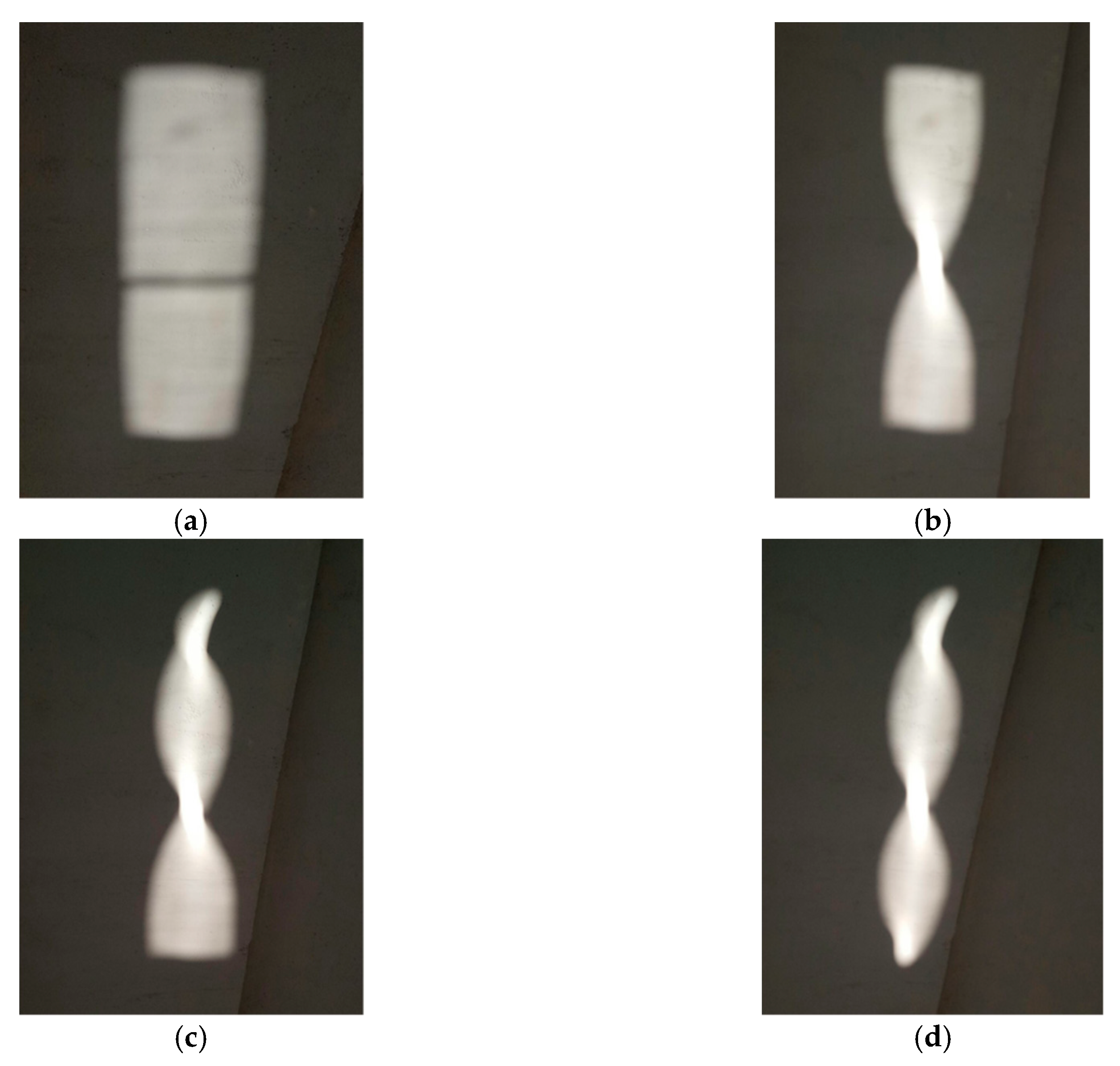
Figure 9 shows how the image reflected is adjusted when each of the three ribs are clamped consecutively.
The first image (
Figure 9a) corresponds to the mirror before clamping the ribs; a reflected rectangular image can be seen that perfectly matches the dimension of the mirror.
Figure 9b is the image reflected when the center rib is clamped; it is clear how the image is adjusted to the cylindrical shape of the rib’s range; a small area of concentrated heat flux in this zone emerges. When a second rib (one of the extremes) is clamped, another change in the reflected image is noticeable, and again a solid concentration region is created in the rib’s range. However, in
Figure 9c, it can be seen that the mirror does not adopt the desired curvature in the area between both ribs because a flat region persists in the reflected image, i.e., beam solar radiation is reflected but non-concentrated. Finally, the third rib (located in the opposite extreme) is clamped and the result is the same as the previous (
Figure 9d), i.e., the mirror adopts the cylindrical geometry only in the rib’s range. A similar configuration was tested adding two more ribs, but the results were the same; the mirror adopts the cylindrical shape exclusively in the ribs range and the flatness in other areas of the mirror facet persisted. This is due to the elastic property of the mirror used. It was concluded that this is not an acceptable solution to manufacture mirror facets for the LFR configuration and size considered.
4.2. Naked Mirror Mechanically Bended by Metallic Bars Glued to it
The application of this solution to configure and manufacture a mirror facet for the LFR proposed did not offer the targeted cylindrical geometry. The glued section attached to the longitudinal bar creates a flat zone in the center of the mirror. Then, the two free extremes of the mirror are pushed up, resulting in a particular geometry, as represented in
Figure 10.
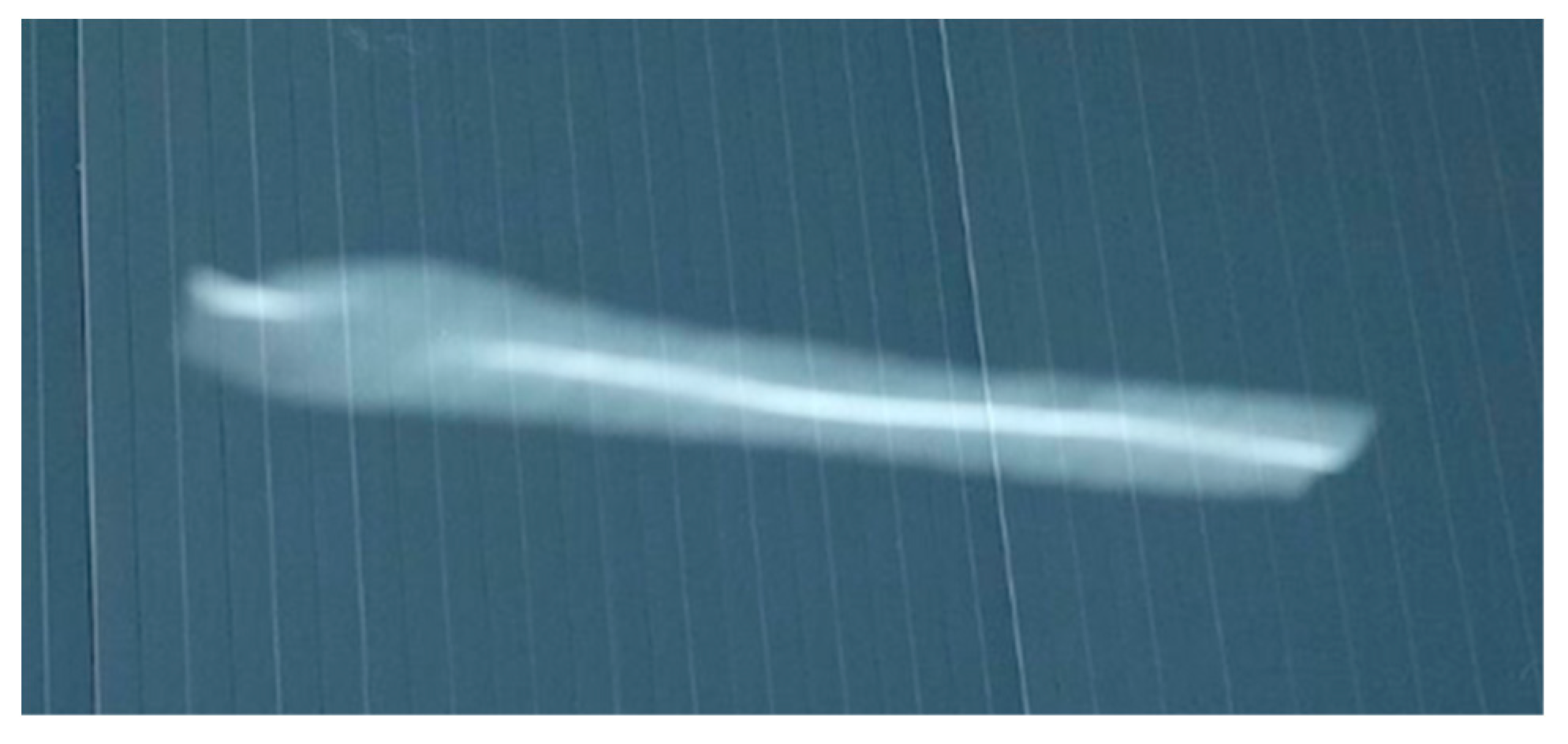
The effect of this particular geometry onto the reflected image is an upgrade compared with the former configuration. Nevertheless, there are some diffused areas in the reflected image where the concentration of the solar radiation does not take place or is less noticeable than expected.
Figure 11 shows the image reflected by a mirror facet manufactured considering this configuration. It can be seen that the reflected image presents a significant amount of rays concentrated onto the center line, creating a bright thick line. Also, the dispersion of other rays around the center line forming a lighter illuminated area can be seen. There is a discontinuation of the concentrated line. Presumably, this is caused by a glued malfunction between the bar and the mirror.
Besides the optical performance of this configuration, there is a significant setback in the assembly. To achieve the desired focus length, every facet must be individually adjusted to it. That means every one of the six bolts must be manually screwed up until the desired focus length is accomplished. The procedure is not viable taking into consideration that the solar collector unit considered in this study is composed of 120 facets. Moreover, screwing the bolt to the optimal position in which the mirror reaches the focus is a source of possible errors leading to an optical performance’s uncertainty in the operation of the collector.
4.3. Mirror Glued by Vacuum over a Curved Rectangular Plate Attached to a set of Preformed Ribs
Regardless of the optical outcome, this configuration is discarded because of the excessive weight of the components. The use of steel, with density equal or higher than 7850 kg/m3 (value depends on the type of steel used), leads to a weight higher than 6.5 kg per facet. This is contrary to the premise of getting lightweight facets.
4.4. Mirror Glued by Vacuum to a Single Curved Plate
The type of mirror facet built following this manufacturing process is composed of an aluminum curved plate with a thin glass-silvered mirror that is glued to its surface. The density of the aluminum is about 2700 kg/m3, which makes lighter facets when compared to the use of steel for the support structure.
The result of this assembly (see
Video S1) is considerably more satisfactory than the former.
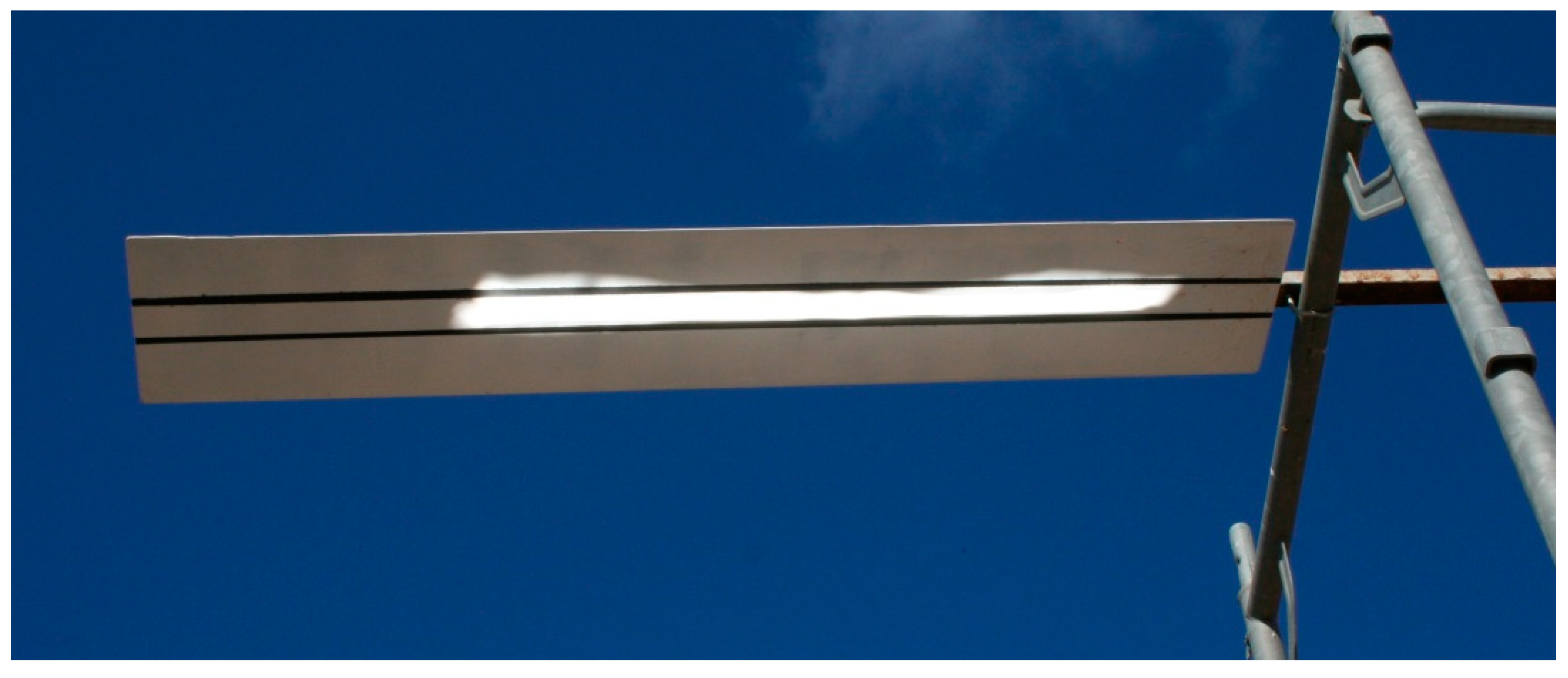
Figure 12 shows the concentrated solar radiation reflected by one facet on the surface of a Lambertian target, which was specially prepared with two longitudinal marks creating a 5 cm channel that allows appreciating the geometrical quality of the reflector.
The target is localized at the same height as the receiver, consequently at an equal distance to the focal length of the facet, which is 2.3 m for the LFR design considered in this study.
Figure 12 shows how, in this preliminary test, a large amount of the concentrated solar radiation is within the 5 cm longitudinal channel. The image reflected is virtually a solid rectangle of 5 cm width and 1 m long, with almost non-dispersed radiation or discontinuity. Taking into consideration that the width of the mirror is 28 cm, the concentration ratio of the facet is 5.6.
After studying all four configurations and the results obtained from manufacturing the mirror facets for the considered LFR, the configuration based on a mirror glued by vacuum to a single curved aluminum plate is the one selected to manufacture 120 facets for the LFR collector prototype considered.
Geometrical Qualification of the Manufactured Facets
To complement and sustain the manufacturing process of the LFR facets, a verification of the geometry and the optic is carried out. The technique applied to measure the geometrical quality of the facets is close-range photogrammetry [
10].
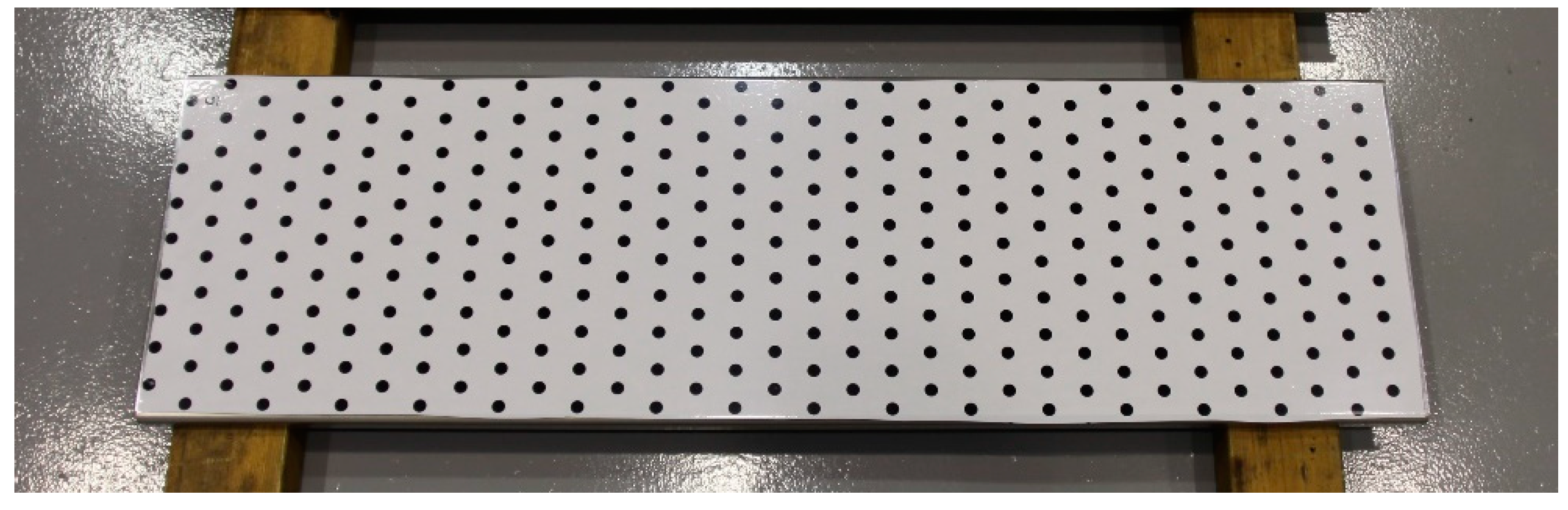
The photogrammetry process involves taking a set of well-planned photographs to the reflective surface of the facet. The facet’s surface is previously covered with a target pattern, printed in an adhesive white vinyl sheet. The targets are black circles of 1 cm diameter arranged in rows and separated from each other by 2 cm. Finally, 323 target circles are distributed in the reflective surface as shown in
Figure 13.
Once the target is settled, the reflective surface is photographed from different angles covering 360 degrees around the facet, positioning the camera in horizontal and vertical orientation to compensate for the optical aberration of the system.
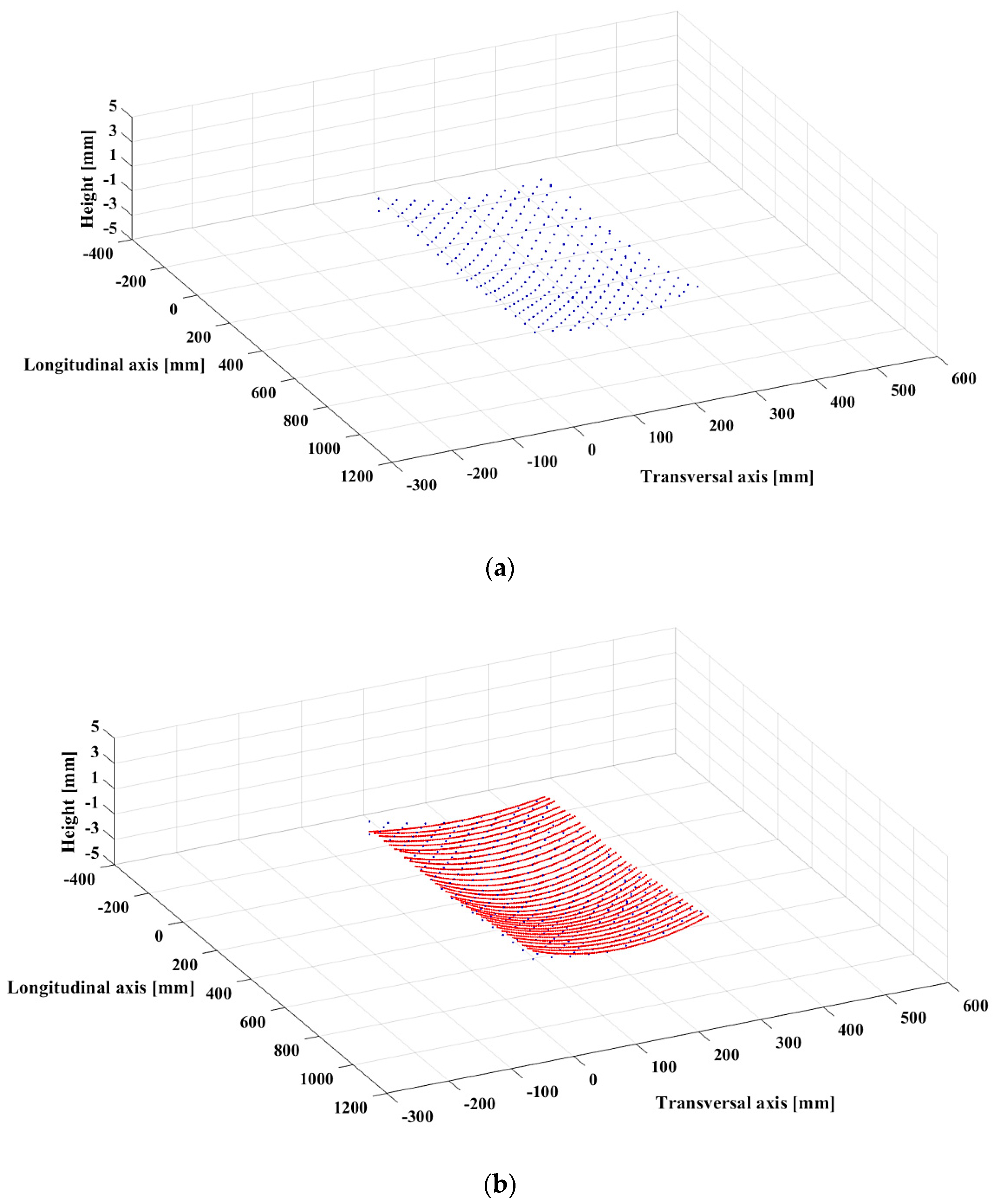
The next step consists in post-processing the images. In
Figure 14a, a representation of each point that compiles the reflective surface can be seen. Every blue circle represents a specific point of the facet’s reflective surface and their spatial position is represented by their Cartesian coordinates.
The sag of a circumference arc is selected as the parameter to evaluate the accuracy of the accomplished facet’s geometry. The sag is defined as the height of the arc; it is the perpendicular distance between the midpoint of the arc’s chord to the arc itself. This parameter is directly related to the radius of the facet’s curvature. Every arc formed by the 34 groups of targets aligned in the transversal axis is built, and then they are compared among them. The facets are designed with a specific radius of curvature, which is 6.5 m in the design considered in this study, and the sag that corresponds to this radius is 1.51 mm.
Figure 14b shows the arc that best fits to every transversal aligned target group.
The sag of each arc contained in the reflective surface depends on the optical behavior of the facet. The accuracy of the reflected image corresponds to a constant value of the sag along the facet. However, the manufacturing process entails different error sources that divert the final geometry from the defined one. The graph shown in
Figure 15 represents the deviation of each calculated arc’s sag in the longitudinal axis of a facet compared to the sag of the reference curvature radius.
Each blue dot represents the sag of the corresponding circumference arc at a specific longitudinal position in the facet. The points are arranged according to the value of the designed sag represented in a dotted red line (1.51 mm). The magnitude of the deviation in the black lines across each point can be appreciated. Smaller values of the sag are linked to bigger curvature radius.
Figure 15 shows a maximum deviation of 0.95 mm when the inferred value of the sag is 0.56 mm at the left side of the longitudinal axis. Then, the magnitude decreases until reaching the middle zone in which the sag is negligible and slightly higher than the designed value. Finally, the value of the sag decreases again with a smoother ratio.
As it was mentioned before, the variation of the sag along the longitudinal axis of the facet has a consequence in the reflected image.
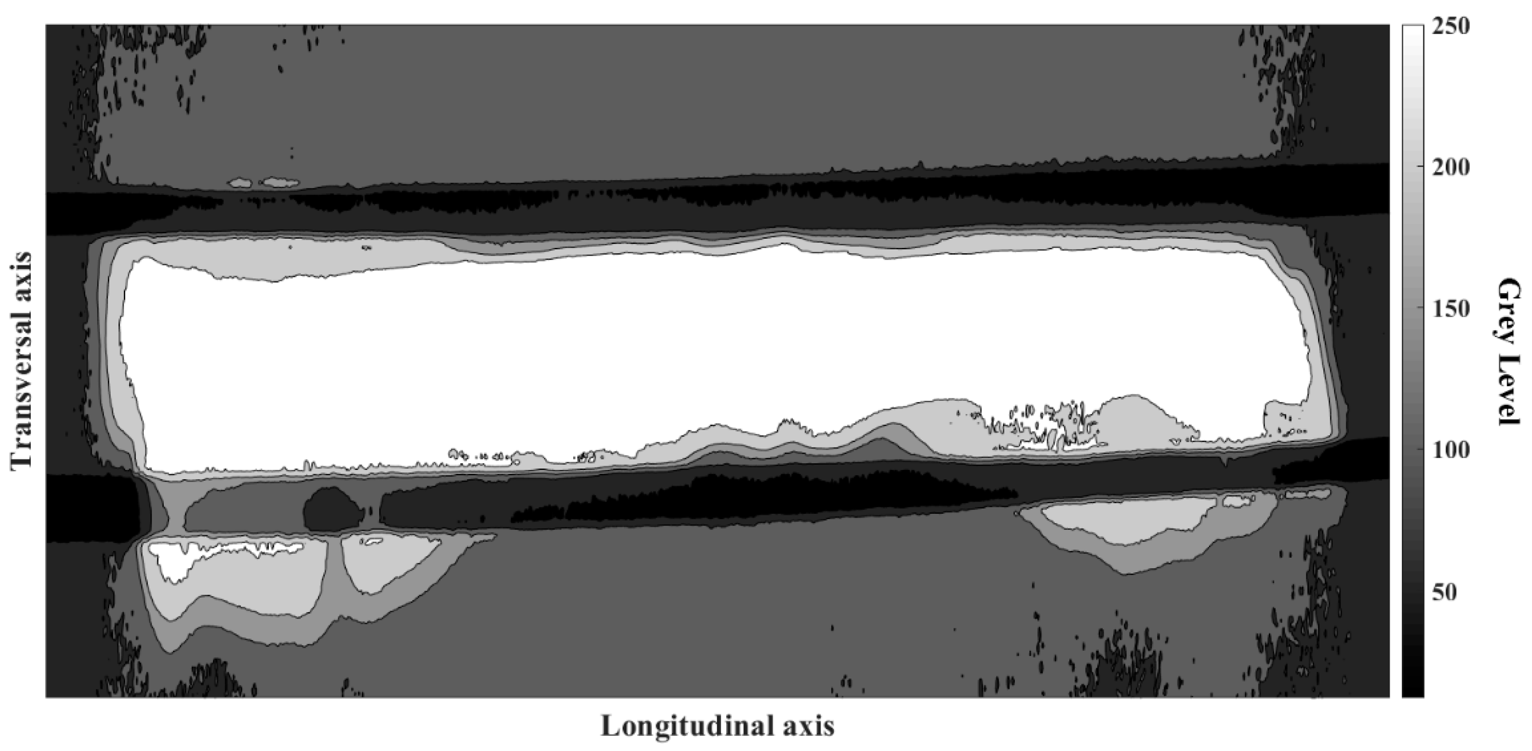
Figure 16 shows the same image as
Figure 12, converted into a luminance map level using a RBG colormap, where 255 is the maximum value in the gray color scale representing the higher concentrated flux. The luminance distribution presents a perfect match with the deviation of the sag graph (
Figure 15). The reflected image displays a thicker and dispersed pattern at the extremes of the longitudinal axis, which corresponds to a lower value of the sag. On the other hand, in the center of the facet, where the value is closer to the optimal, the image is consistently collimated. To address the geometrical errors in the manufacturing process, it is convenient to say that the bending machine used to shape the aluminum plates is designed to achieve pronounced or closed curves, and certainly, does not have the required optical precision to guarantee the desired consistency in the manufactured plates. To improve the quality of facets manufactured following the procedure presented in
Section 3.2.4, an adequate selection of the bending machine is crucial to guarantee the optical quality of the mirror facets manufactured.
5. Conclusions
Different procedures to manufacture linear Fresnel reflector’s mirror facets are detailed in this article. The first step before starting the manufacturing is the selection of the geometrical shape of the facet. Three mirror shapes are addressed: flat, cylindrical and parabolic. The one that leads to the simplest manufacturing process without compromising the optical behavior is the cylindrical-shaped mirror, which is defined as the proper configuration.
Four configurations of the structure that support and shape the mirror into the facet are described. It is found that the assembly composed by a mirror glued by vacuum to a single curved aluminum plate delivered the best results. This is based on the optical performance accomplished, altogether with technical aspects of the assembly process that provide specific and easy-to-apply steps to accomplish a larger manufacturing process. The sag of a circumference arc of the facets is determined as the geometrical parameter to characterize the accuracy of the curvature accomplished.
From the possible error sources found, one step is highlighted as the most susceptible to improvement. This is the bending process of the metallic plate used as support of the mirror. The use of a more precise bending machine would create a smaller deviation of the sag along the facet. Besides the errors, the image reflected is definitely optimum in terms of the amount of concentrated light into the target area. Also, the shape of the reflected image is within the expected boundaries.
Finally, this work aims to be a useful tool in the construction of linear Fresnel solar collectors, spreading the practical experience on the development of this concentrating solar technology development.
Author Contributions
Conceptualization, D.P.-I. and L.V.; methodology, D.P.-I. and L.V.; experimentation D.P.-I., J.G. and J.R.; validation, D.P.-I. and J.F.-R.; writing, D.P-I. and L.V; funding acquisition, L.V.
Funding
The research work leading to this article received ERDF funds from the Spanish government within the framework of the SOLTERMIN project (Ref. ENE2017-83973-R) of the Ministerio de Economía, Industria y Competitividad (Spanish Ministry of Economy, Industry and Competitiveness).
Acknowledgments
The authors would like to thank the Operation and Maintenance team of the Plataforma Solar de Almería for their continuous support in the whole manufacturing process.
Conflicts of Interest
The authors declare no conflict of interest.
Acronyms
| LFR | linear Fresnel reflector |
| PTC | parabolic trough collector |
Symbols
| r | ray impinging in mirror’s aperture |
| P | mirror point |
| f | focal distance of the cylindrical mirror (m) |
| θ | incidence angle (°) |
| B | distance from the center of circumference to the focal point (m) |
| O | center of the circumference |
| M | mirror point |
| F | force applied to the mirror |
References
- Vannoni, C.; Tobergte, D.R.; Curtis, S. Potential for Solar Hear in Industrial Processes. J. Chem. Inf. Model. 2013, 53, 1689–1699. [Google Scholar] [CrossRef]
- Kalogirou, S.A. Solar thermal collectors and applications. Prog. Energy Combust. Sci. 2004, 30, 231–295. [Google Scholar] [CrossRef]
- Fernandez-Garcia, A.; Zarza, E.; Valenzuela, L.; Perez, M. Parabolic-trough solar collectors and their applications. Renew. Sustain. Energy Rev. 2010, 14, 1695–1721. [Google Scholar] [CrossRef]
- Sahoo, S.S.; Singh, S.; Banerjee, R. Analysis of heat losses from a trapezoidal cavity used for Linear Fresnel Reflector system. Sol. Energy 2012, 86, 1313–1322. [Google Scholar] [CrossRef]
- Sait, H.H.; Martinez-Val, J.M.; Abbas, R.; Munoz-Anton, J. Fresnel-based modular solar fields for performance/cost optimization in solar thermal power plants: A comparison with parabolic trough collectors. Appl. Energy 2015, 141, 175–189. [Google Scholar] [CrossRef]
- Feldhoff, J.F. Linear Fresnel Collectors A Technology Overview of CSP Systems; SFERA Summer School: Almería, Spain, 2012; pp. 1–30. [Google Scholar]
- Abbas, R.; Muñoz, J.; Martínez-Val, J.M. Steady-state thermal analysis of an innovative receiver for linear Fresnel reflectors. Appl. Energy 2012, 92, 503–515. [Google Scholar] [CrossRef]
- Kidger, M.J. Fundamental Optical Design; SPIE press: Bellingham, WA, USA, 2002. [Google Scholar]
- Pulido-Iparraguirre, D.; Valenzuela, L.; Serrano-Aguilera, J.J.; Fernández-García, A. Optimized design of a Linear Fresnel reflector for solar process heat applications. Renew. Energy 2019, 131, 1089–1106. [Google Scholar] [CrossRef]
- Fernández-Reche, J.; Valenzuela, L. Geometrical assessment of solar concentrators using close-range photogrammetry. Energy Procedia 2012, 30, 84–90. [Google Scholar] [CrossRef]
Figure 1.
Scheme of the three mirror’s shape addressed: (a) flat-shape mirrors, (b) parabolic-shaped mirrors, and (c) cylindrical-shaped mirrors.
Figure 1.
Scheme of the three mirror’s shape addressed: (a) flat-shape mirrors, (b) parabolic-shaped mirrors, and (c) cylindrical-shaped mirrors.
Figure 2.
Scheme of the reflection in a cylindrical mirror.
Figure 2.
Scheme of the reflection in a cylindrical mirror.
Figure 3.
Scheme of a LFR.
Figure 3.
Scheme of a LFR.
Figure 4.
Scheme of the assembly for naked mirror over shaped ribs: (a) mirror before ribs clamping and (b) mirror after ribs clamping.
Figure 4.
Scheme of the assembly for naked mirror over shaped ribs: (a) mirror before ribs clamping and (b) mirror after ribs clamping.
Figure 5.
Scheme of the assembly for naked mirror mechanically bended by metallic bars glued to it: (a) mirror before being pushed by bolts and (b) mirror after being pushed by bolts.
Figure 5.
Scheme of the assembly for naked mirror mechanically bended by metallic bars glued to it: (a) mirror before being pushed by bolts and (b) mirror after being pushed by bolts.
Figure 6.
Assembly of a curved rectangular plate attached to a set of preformed ribs: (a) front view of the assembly and (b) lateral (longitudinal) view of the assembly.
Figure 6.
Assembly of a curved rectangular plate attached to a set of preformed ribs: (a) front view of the assembly and (b) lateral (longitudinal) view of the assembly.
Figure 7.
Mirror glued by vacuum to a curved plate: (a) pleated mirror facet and (b) vacuum gluing process.
Figure 7.
Mirror glued by vacuum to a curved plate: (a) pleated mirror facet and (b) vacuum gluing process.
Figure 8.
Assembly scheme of the suction cup into a mirror facet: (a) facet presented over the alignment device, (b) facet adjusted over the alignment device, (c) silicone cordon applied on the facet, (d) suction cups attached on the facet, (e) exploded view of the suction cup mounting process, and (f) suction cup mounted on the facet.
Figure 9.
Reflected image for the assembly of naked mirror over shaped ribs facet configuration. (a) Non ribs clamped; (b) Middle ribs clamped; (c) Middle and one external ribs clamped; (d) Middle and both external ribs clamped.
Figure 9.
Reflected image for the assembly of naked mirror over shaped ribs facet configuration. (a) Non ribs clamped; (b) Middle ribs clamped; (c) Middle and one external ribs clamped; (d) Middle and both external ribs clamped.
Figure 10.
Scheme of transversal section of naked mirror mechanically bended by metallic bars glued to it.
Figure 10.
Scheme of transversal section of naked mirror mechanically bended by metallic bars glued to it.
Figure 11.
Reflected image for the assembly of naked mirror mechanically bended by metallic bars glued to it.
Figure 11.
Reflected image for the assembly of naked mirror mechanically bended by metallic bars glued to it.
Figure 12.
Concentrated radiation reflected into a Lambertian target.
Figure 12.
Concentrated radiation reflected into a Lambertian target.
Figure 13.
Target pattern over the reflector surface of the facet for the photogrammetry process.
Figure 13.
Target pattern over the reflector surface of the facet for the photogrammetry process.
Figure 14.
Photogrammetry’s points and representative arcs spatially represented: (a) photogrammetry points and (b) representative arcs.
Figure 14.
Photogrammetry’s points and representative arcs spatially represented: (a) photogrammetry points and (b) representative arcs.
Figure 15.
Deviation in millimeters of the calculated (measured) sag with respect to the sag of the designed geometry.
Figure 15.
Deviation in millimeters of the calculated (measured) sag with respect to the sag of the designed geometry.
Figure 16.
Luminance distribution of the concentrated radiation reflected by a prototype LFR mirror facet into a Lambertian target.
Figure 16.
Luminance distribution of the concentrated radiation reflected by a prototype LFR mirror facet into a Lambertian target.
© 2019 by the authors. Licensee MDPI, Basel, Switzerland. This article is an open access article distributed under the terms and conditions of the Creative Commons Attribution (CC BY) license (http://creativecommons.org/licenses/by/4.0/).

 ,
, 


