Abstract
This paper proposes a novel finite control set model predictive control (FCS-MPC) strategy with merely grid-injected current sensors for an inductance-capacitance-inductance (LCL)-filtered grid-tied inverter, which can obtain a sinusoidal grid-injected current whether three-phase grid voltages are balanced or not. Compared with the conventional FCS-MPC method, four compositions are added in the proposed FCS-MPC algorithm, where the grid voltage observer (GVO) and Luenberger observer are combined together to achieve full status estimations (including grid voltage, capacitor voltage, inverter-side current, and grid-injected current), while the sequence extractor and the reference generator are applied to eliminate the double frequency ripples of the active or reactive power, or the negative sequence component (NSC) of the grid-injected current caused by the unbalanced grid voltage. Simulation model and experimental platform are established to verify the effectiveness of the proposed FCS-MPC strategy, with full status estimations under both balanced and unbalanced grid voltage conditions.
1. Introduction
Grid-tied inverters have been widely utilized in distributed generation systems, since they are the interfaces between DC sources and power grids [1,2]. In regards to the control of grid-tied inverters, besides the classical linear control schemes [3,4], a large number of nonlinear control strategies, such as model predictive control (including continuous control set model predictive control (CCS-MPC) and finite control set model predictive control (FCS-MPC)), sliding mode control, passivity-based control [5,6,7], and so on, were proposed. Among them, the FCS-MPC attracted significant attentions in recent years, owing to the technique advantages, including no need of the modulator, straightforward handling of nonlinearities and constraints, quick dynamic responses, and simple implementation [8,9,10,11].
Recently, Falkowski et al. [12] proposed an FCS-MPC method for the inductance-capacitance-inductance (LCL)-filtered grid-tied ac-dc converter, which can damp the oscillations caused by the filter resonance and acquire the high performance of grid currents. However, this FCS-MPC method requires to measure the inverter-side current, the capacitor voltage grid voltage, and the grid-injected current by sensors, increasing the cost and complexity. Aiming at reducing the number of sensors, many sensorless control schemes, such as virtual flux [13,14], state observer [15,16], and so on, were widely adopted. However, these control schemes are usually designed under the ideal grid voltage condition, and the negative effects caused by the negative sequence component (NSC) are not considered. Therefore, under the unbalanced grid voltage condition, the feasibilities of current sensorless control schemes need be further verified [17].
To alleviate the adverse effects of the unbalanced grid voltage, the positive sequence component (PSC) and the NSC of the grid voltages are required to be separated first, and then applied in the control algorithm [18,19,20,21]. In [18], for the distributed generation inverter, a flexible reference generator based on positive and negative active and reactive powers, was proposed to keep feeding the grid and support the grid voltage under the unbalanced grid voltage condition. In [19], to overcome the distortion of grid-injected currents caused by the unbalanced grid voltages, Zheng et al. proposed an improved virtual synchronous generator control method with the additional positive-sequence current adjuster, allowing the reference currents to track the positive sequence currents and inhibiting the negative-sequence components. In [20], Suul et al. proposed a virtual-flux-based method for the voltage-sensorless grid synchronization under variable grid frequency and unbalanced voltage conditions, integrating the functions of frequency-adaptive bandpass filtering, the virtual flux estimation, and the sequence separation into one operation. In [21], Yang et al. proposed a sliding-mode grid voltage observer for the voltage-sensorless operation under an unbalanced network, separating the PSC and NSC inherently. The variables of methods proposed in [18,19] are all based on the full state measurements, while only one kind of sensor is reduced in [20,21]. Note that it is of great challenge for the LCL-filtered grid-tied inverter to further reduce the number of sensors, especially under the unbalanced grid voltage condition.
In this paper, a novel FCS-MPC approach for the control of an LCL-filtered grid-tied inverter using merely grid-injected current sensors under the unbalanced grid voltage condition has been presented. The method is based on four observations instead of the state measurements (called full status estimations in this paper). In the proposed method, the inverter-side current, the capacitor voltage, and the grid-injected current are estimated via the Luenberger observer, while the grid voltage and its quadrature signal are observed by the second order generalized integrator (SOGI)-based GVO. According to the output of the GVO, the PSC and NSC of the estimated grid voltage are separated to generate the reference of grid-injected current, which are used for the FCS-MPC. The PSC of the estimated grid voltage acts as the input of the synchronous reference frame phase-locked loop (SRF-PLL), making the system obtain good estimating accuracy, when the grid frequency varies under unbalanced gird voltage condition. Three different control targets for generating the reference of grid-injected current—(1) to eliminate the active power ripple; (2) to eliminate the reactive power ripple; and (3) to achieve the balanced and sinusoidal grid-injected currents—are utilized, and the effectiveness of the proposed FCS-MPC method is verified via simulations and experiments under both balanced and unbalanced grid voltage condition.
The rest of this paper is organized as follows. The conventional FCS-MPC method for the LCL-filtered grid-tied inverter is first introduced in Section 2. Then, the theoretical analysis of the proposed FCS-MPC scheme with full status estimations under the unbalanced grid voltage condition is described in Section 3. Next, the detailed implementation of the proposed FCS-MPC strategy is presented in Section 4, Section 5 and Section 6 and demonstrate the simulation and experimental results to verify the effectiveness of the proposed FCS-MPC algorithm, respectively. Finally, a conclusion is drawn in Section 7.
2. Conventional FCS-MPC Method for LCL-Filtered Grid-Tied Inverter
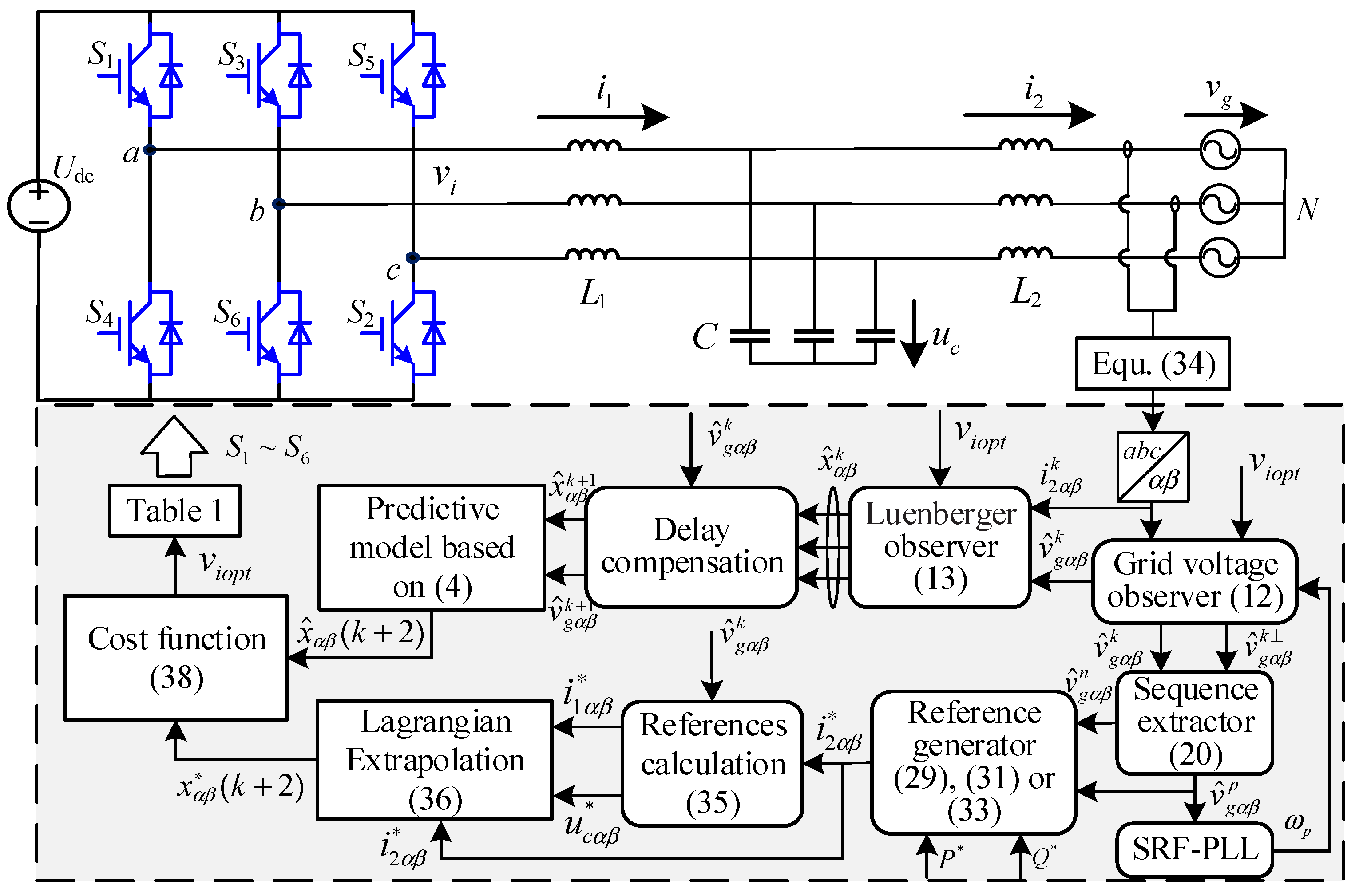
The structure of the three-phase grid-tied inverter with LCL filter powered by a constant DC voltage source Udc is depicted in Figure 1. As shown in Figure 1, vi, uc, and vg denote the inverter output voltage, the capacitor voltage, and the grid voltage, respectively. The currents of i1 and i2 represent the inverter-side current and the grid-injected current, respectively. These variables represent state space complex-vectors in the αβ stationary coordinate system, such as vgαβ = vgα + jvgβ. The symbol “^” indicates the variables are estimated values instead of the measured values, and the notation “*” signifies the reference values, respectively.
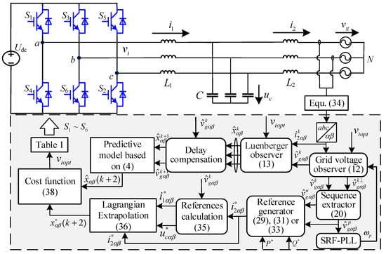
Figure 1.
Proposed FCS-MPC algorithm for inductance-capacitance-inductance (LCL)-filtered grid-tied inverter with full status estimations under the unbalanced grid voltage condition.
2.1. Discrete-Time Model of LCL Filter
By neglecting the parasitic resistances, the dynamic model of inverter system can be expressed as follows:
where the variables of current and voltage are expressed in the form of complex-vectors in the αβ stationary coordinate system (i.e., i1αβ = i1α + ji1β, i2αβ = i2α + ji2β, viαβ = viα + jviβ, ucαβ = ucα + jucβ, vgαβ = vgα + jvgβ).
Then, by taking the variables i1, i2, and uc as the system states, the dynamic model of inverter system can be further described by:
where
Additionally, x = [i1αβ i2αβ ucαβ]T is the state vector and y = i2αβ is the output of the system, which denotes that only the grid-injected current is measured in this paper. The inverter output voltage viαβ is obtained by the combinations of switching signals Sa, Sb, Sc, which are described in Table 1, and it can be expressed as a state space complex-vector in αβ stationary reference frame:

Table 1.
Switching states and voltage vectors.
For the digital implementation of the control algorithm, the continuous-time dynamic model of the LCL filter can be represented in discrete time (the sampling time is Ts) by adopting the zero-order-hold (ZOH) discretization method:
where matrices A1, B1, B2 are
2.2. Conventional FCS-MPC Scheme
With the improved calculation power, the new generation of the digital signal processor (DSP), the field-programmable gate array (FPGA), and the dSPACE platform were utilized to implement the computationally-complex control algorithm for power electronics and drives. Consequently, the FCS-MPC method attracted a lot of attention in recent years, since the problem of computational burden can be preliminary solved. Unlike other linear or nonlinear control methods applied in the grid-tied inverter, the FCS-MPC algorithm has an obvious advantage of no need of a modulation stage. For the FCS-MPC scheme, by adopting a traversal method (each inverter output voltage vector is used to evaluate a cost function), the inverter output voltage vector with minimum cost function was selected. Then, the driving signal could be deduced according to Table 1.
For the LCL-filtered grid-tied inverter, the conventional FCS-MPC algorithm was implemented in the following steps [12]:
- Measure i1, i2, uc, and vg by using the current and voltage sensors;
- Calculate and according to the given reference of grid-injected current ;
- Deduce the references of three state variables at next step by utilizing the Lagrangian Extrapolation method;
- Obtain the predictions of three state variables in the next sampling instant x (k + 1) for all possible inverter output voltage vectors based on the discrete-time model of the LCL filter expressed in Equation (4);
- Construct the cost function and define the weighting factor;
- Select the optimal inverter output voltage vector by minimizing the cost function;
- Acquire the driving signal according to Table 1.
3. Theoretical Analysis of the Proposed FCS-MPC Scheme with Full Status Estimations under Unbalanced Grid Voltage Condition
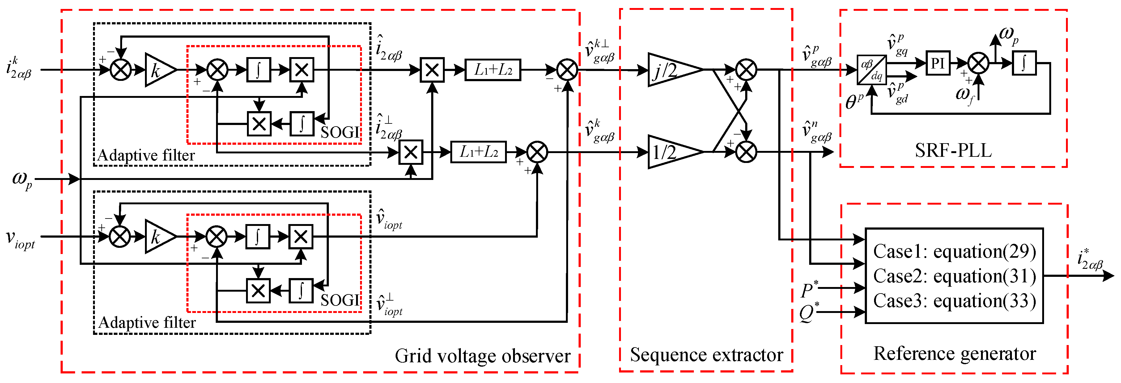
For the conventional FCS-MPC algorithm, it requires two kinds of current sensors to measure the inductor currents as well as two types of voltage sensors to probe the capacitor voltages and the grid voltages, increasing the cost and control complexity. In order to reduce the number of sensors and enhance the control reliability under unbalanced grid voltage condition, a novel FCS-MPC strategy is proposed in this paper. As depicted in Figure 1, compared with the conventional FCS-MPC scheme described in Section 2, four compositions including the GVO, the Luenberger observer, the sequence extractor, and the references generator are added in the proposed FCS-MPC strategy, which can achieve full status estimations and eliminate the negative effects caused by the unbalanced grid voltages. The detailed diagram of the proposed strategy is depicted in Figure 2.
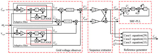
Figure 2.
The block diagram of the proposed strategy under the unbalanced grid voltage condition.
3.1. Grid Voltage Observer
As shown in Figure 2, the adaptive filter consists of the SOGI, the filter gain coefficient k, and the output feedback. It is vital to know the value of the grid angular frequency when the adaptive filter is utilized. In practice, the grid frequency may deviate from the rated value. When assuming that the grid frequency is a constant, the effect of the adaptive filter will drop sharply when the grid frequency shifts, making it difficult to obtain the correct information of the grid voltage. Hence, an approach for detecting the grid frequency is required.
In a three-phase system, the phase lock method of SRF-PLL is usually adopted. Under the ideal grid voltage condition, the SRF-PLL yields great performance and tracks the variable grid frequency accurately. However, under the unbalanced grid voltage condition, the overall dynamic performance of the SRF-PLL would become unacceptably deteriorated, due to the negative effects caused by the unbalanced grid voltages. For handling this problem, a PLL based on the decoupled double synchronous reference frame is utilized [22], which isolates the PSC and NSC of the grid voltages, and then takes the PSC as the input signal of PLL. Additionally, the output grid angular frequency is taken as the input angular frequency of the adaptive filter, making the system achieve the frequency-adaptive under the unbalanced grid voltage condition.
In order to analyze the performance of the adaptive filter on tracking the grid frequency, the transfer functions are expressed as follows:
where ωp and k set the center angular frequency and the damping factor of the adaptive filter, respectively. u is the input signal of the adaptive filter, while and are the output signals. The amplitude and phase response of the adaptive filter can be calculated as:
It can be deduced from Equations (7) and (8), if the angular frequency ω of the input signal u is equal to the center angular frequency ωp in the steady state, , , . Consequently, we can get the conclusion that in combination with the SRF-PLL, although the grid frequency is variable, the adaptive filter can track the input signals accurately without any error in the steady state. And, the output signals are a pair of orthogonal quantities, where and u are in same phase, but is 90° lag respect to the input signal u.
For the LCL-filtered grid-tied inverter system, due to the high impedance of the filtering capacitor at low frequency, the current of this capacitor can be neglected. When neglecting the current of the filtering capacitor, the continue-time model of grid-tied inverter with LCL filter in αβ coordinate system can be expressed as follows:
Since the differential of the sinusoidal signal can be transformed into the in-phase or inverted value of its quadrature signal, based on the adaptive filter, Equation (9) can be written in the following form:
And then, Equations (10) and (11) can be simplified as follows:
where , represent the outputs of the GVO (i.e., the estimated grid voltage and its quadrature signal, respectively). , and , are the outputs of the adaptive filter, whose input signals are viopt and i2, respectively.
3.2. Luenberger Observer
To further reduce the number of sensors, the Luenberger observer is adopted to combine with the GVO, where the inverter-side current sensors and the capacitor voltage sensors can be saved.
The state-space model of the Luenberger observer in the discrete-time domain can be described as follows:
where L = [l1 l2 l3]T represents the observer gain vector and Cc = [0 1 0] is the output vector, which denotes that the grid-injected current is measured in this paper. The grid voltage is observed by using GVO. By defining the estimation error of , based on Equation (13), the dynamics of state observation error is derived as:
Hence, if the matrix of A1-LCc is Hurwitz, the error vector will converge to zero. The observability matrix is full rank (), which indicates that the system is observable. Therefore, the eigenvalues of the observer can be assigned arbitrarily, and the characteristic polynomial of the observer can be set as:
where p1, p2, and p3 are the desired poles of the Luenberger observer. In order to obtain the values of L, p1, p2, and p3 need to be ensured. It is usually easier to identify the poles first in the s-domain and then map them to the z-domain via z = exp(sTs). In the s-domain, the closed-loop characteristic polynomial can be described as . Then, the poles p1, p2, and p3 in the z-domain can be expressed as follows:
where the pair of complex-conjugate poles, determined by ζor and ωor, are set to decide the dominant dynamics of the estimation errors. The real pole αod is located at a higher frequency. ζor is the damping ratio, usually set as 0.707. The range of the natural frequency ωor with respect to the resonance frequency of LCL filter is regarded from 0.5 to 1, and the value of αod is five to 10 times larger than the pair of complex-conjugate poles.
Hence, the gain vector L can be deduced by solving Equation (15). A common method to solve Equation (15) is utilizing the MATLAB function (i.e., acker). When the observer gain vector L is deduced, three state variables can be estimated to be applied to the conventional FCS-MPC algorithm. Hence, the inverter-side current sensors and capacitor voltage sensors can be saved. However, since the negative effects introduced by the NSC of the unbalanced grid voltage are not considered into the control algorithm, the performance will be deteriorated when the grid voltage falls into unbalance.
3.3. Sequence Extractor
To eliminate the adverse effects caused by the NSC of unbalanced grid voltages, the sequence extractor of the grid voltages is required.
Under the unbalanced grid voltage condition, by neglecting the zero sequence components, the positive- and negative-components can be extracted from the grid voltage. Consequently, the grid voltages, which are estimated by utilizing the GVO in this paper, can be described as the sum of PSC and NSC in αβ reference frame:
where is the estimated grid voltage and Vg is its amplitude. , and , are the PSC and NSC of the estimated grid voltage in αβ reference frame, respectively. and are the initial phase angles, and is the grid angular frequency.
By utilizing the delayed signal cancellation (DSC) method [23], when the delay time is Tg/4, Equation (17) can be rewritten as:
Hence, according to Equations (17) and (18), the PSC and NSC of the estimated grid voltage can be deduced in the following equations:
and are 90° lag in respect to and , respectively, thus they are equivalent to a delay of Tg/4. Then, the Equation (19) can be written as follows based on complex-vectors in the αβ stationary coordinate system:
Hence, based on the GVO, the PSC and NSC of the grid voltage can be deduced, which can be utilized for generating the references of grid-injected currents in the next part.
3.4. Reference Generator
For the unbalanced grid voltages and currents without a zero sequence, the grid voltage and grid-injected current also can be expressed as the sum of the PSC and NSC in dq reference frame:
where is the estimated grid voltage obtained by the GVO. and are the PSC and NSC of the estimated grid voltages in the dq rotating reference system, respectively. Similarly, and are the PSC and NSC of the grid-injected currents in the dq rotating reference system, respectively. is the grid angular frequency.
Based on Equation (21), the power of the grid side can be expressed as follows:
According to Equation (22), the active power of p and reactive power of q can be described as:
where p0 and q0 are the average values of the active power and reactive power, respectively. pc2, ps2 and qc2, qs2 are ripples of p and q, respectively. As derived in [24], the average value and ripples of p and q can be further expressed as follows:
The relationship between PSC and NSC of the estimated grid voltage or grid-injected current in the dq rotating coordinate system and αβ stationary coordinate system is
where x represents the estimated grid voltages or grid-injected currents.
By utilizing Equation (25), Equation (24) can be expressed in αβ stationary coordinate system as:
where
It can be seen from Equations (26) and (27) that if the grid voltages are decided, then the inverter has four controllable freedoms (, , , ). This implies that only four control targets can be established [25]. Normally, the average values of the active power p0 and reactive power q0 are controlled to track their references. Consequently, only the remaining two control freedoms can be selected. According to desired control targets, Equations (26) and (27) can be simplified and solved in the following three cases also introduced in [17]:
Case 1: To eliminate active power ripples
In this case, the control target is to remove the double frequency ripples of active power (i.e., pc2 and ps2 in Equation (26) are set to zero (Hence, k1, k2 are zero. qc2 and qs2 are uncontrolled and thus there are reactive power ripples under unbalanced grid voltage. The control objective is equivalent to handle the following equation:
Based on Equations (26), (27), and (28), the reference of the grid-injected current can be calculated as follows:
where , .
Case 2: To eliminate reactive power ripples
In this case, the control target is to eliminate the reactive power ripples (i.e., qc2 and qs2 in Equation (26) are considered as zero). Hence, k3, k4 are both zero. pc2 and ps2 are uncontrolled and thus active power ripples exist under unbalanced grid voltage conditions. The control objective is equivalent to solve the following equation:
Similarly, based on Equations (26), (27), and (30), the reference of the grid-injected current can be obtained as:
where , .
Case 3: To achieve balanced and sinusoidal grid-injected currents
In this case, the control target is to achieve balanced and sinusoidal grid-injected currents, hence, and are regarded as zero. and should be used to satisfy the equations of p0 = P* and q0 = Q*. Since pc2, ps2 and qc2, qs2 are uncontrolled and thus both active power and reactive power ripples exist if grid voltages are unbalanced. The control objective is equivalent to deal with the following equation:
According to Equations (26), (27), and (32), the reference of the grid-injected current can be deduced as:
where , .
A detailed comparison of the proposed FCS-MPC scheme with three different control targets under unbalanced grid voltage is presented in Table 2.

Table 2.
A comparison with three different control targets
4. Detailed Implementation of the Proposed FCS-MPC Strategy
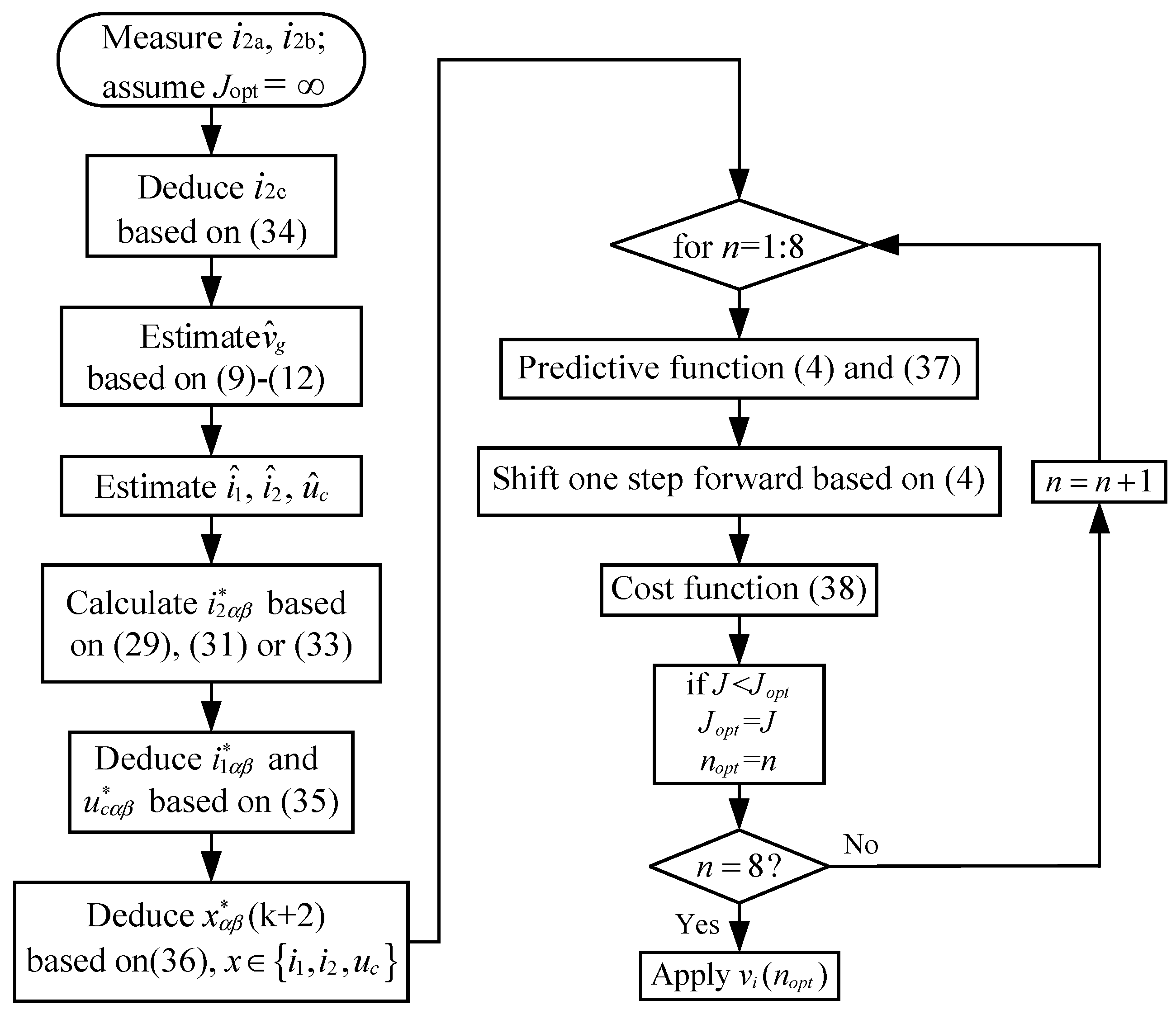
According to the analysis mentioned above, the reference of the grid-injected current can be deduced. Then, it is taken into the FCS-MPC algorithm to alleviate the adverse effects caused by the unbalanced grid voltage. Meanwhile, based on the GVO and Luenberger observer, at least six sensors are saved. Besides, since the practical implementation of FCS-MPC requires considering the negative effect of the computational delay, the discrete-time model of the LCL filter are shifted one step forward in order to eliminate this time delay (i.e., the values at the (k + 2)th instant rather than the (k + 1)th instant should be applied in the cost function) [26]. The flowchart of the proposed FCS-MPC algorithm is depicted in Figure 3, where the detailed implementation steps can be summarized as follows:
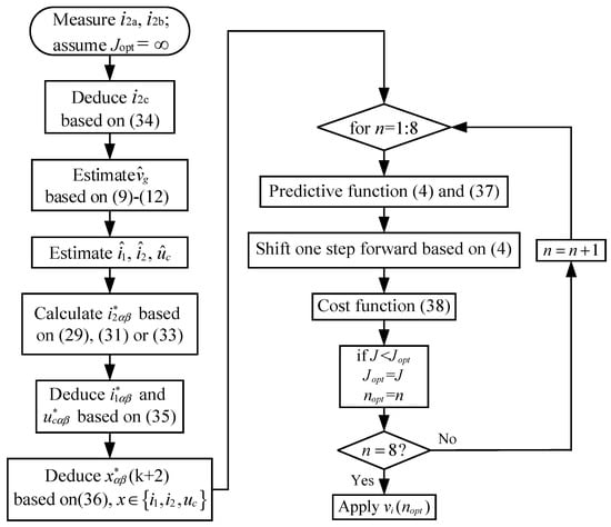
Figure 3.
The flowchart of proposed FCS-MPC strategy.
- Measure the grid-injected currents of phase a and b, and deduce the c-phase grid-injected current by
- Estimate the grid voltage by utilizing the GVO based on Equations (9)–(12);
- Estimate the inverter-side inductor current , the grid-injected current , and the capacitor voltage by using the Luenberger observer, which is based on the observed grid voltages and the measured grid-injected currents;
- Obtain the reference of grid-injected current in αβ stationary coordinate system based on Equation (29), (31), or (33);
- Deduce the references of the inverter-side current and the capacitor voltage in αβ stationary coordinate system based on and .
- Calculate the references of the three estimated state variables x* at the (k + 2)th instant by utilizing the Lagrangian extrapolation, which can be expressed as (x = [i1 i2 uc]T):
- Predict the three estimated state variables x at the (k + 1)th instant according to Equation (4), and calculate the estimated grid voltage at the (k + 1)th instant by
- Predict the three estimated state variables x at the (k + 2)th instant, which is based on the discrete-time model of the LCL filter described in Equation (4);
- Construct the following cost function and then each voltage vector described in Table 1 is taken into the cost function. Consequently, seven different value of cost functions J can be obtained.where ε are the errors of controlled variables between reference value and estimated value. The weighting factor λuc is set to achieve active damping [27], and λi2 is tuned to obtain a high quality grid-injected current [12], and the weighting factors are designed according to [28].
- The inverter voltage vector with minimum cost function viopt is selected. Correspondingly, the driving signals can be deduced according to Table 1.
5. Simulation Results
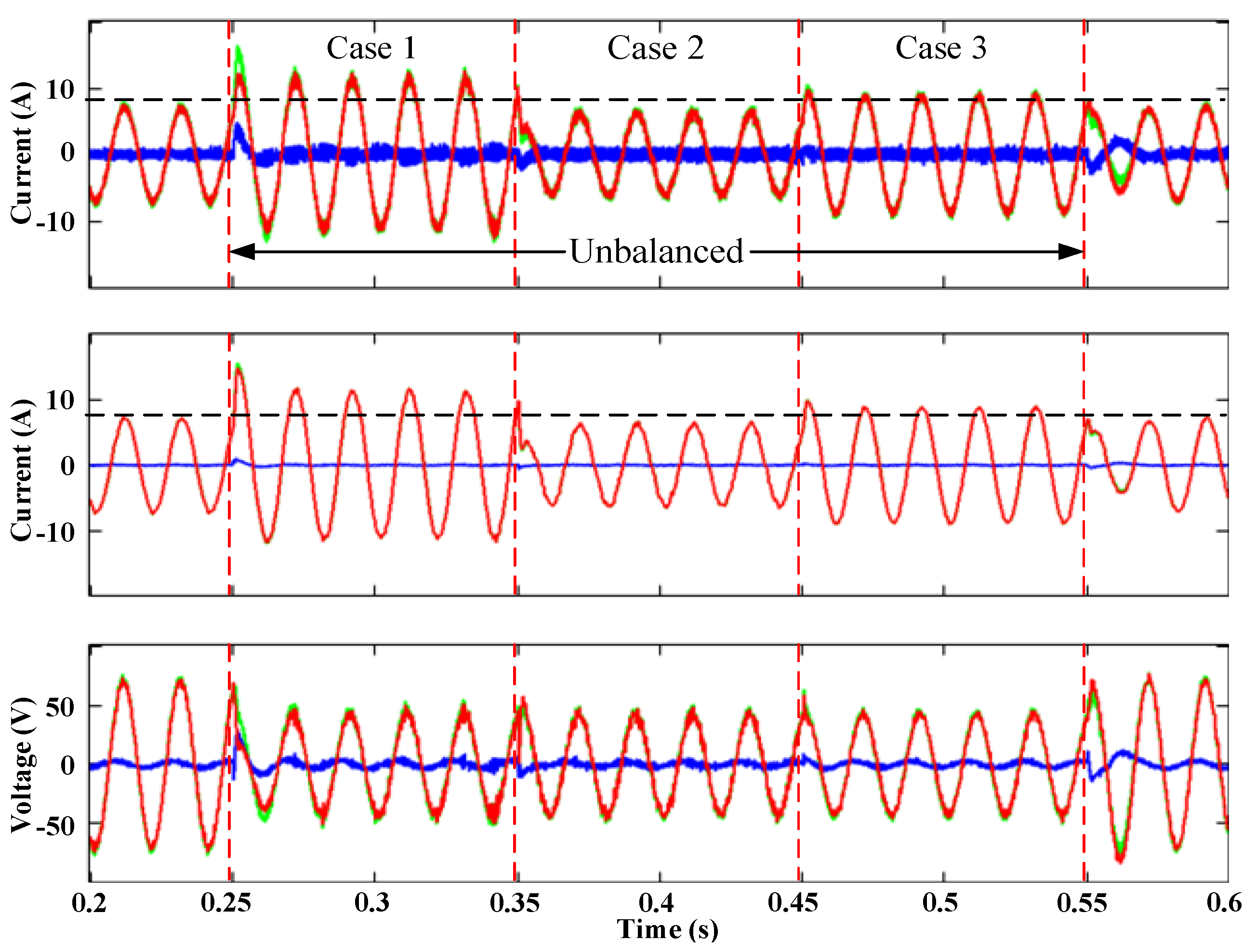
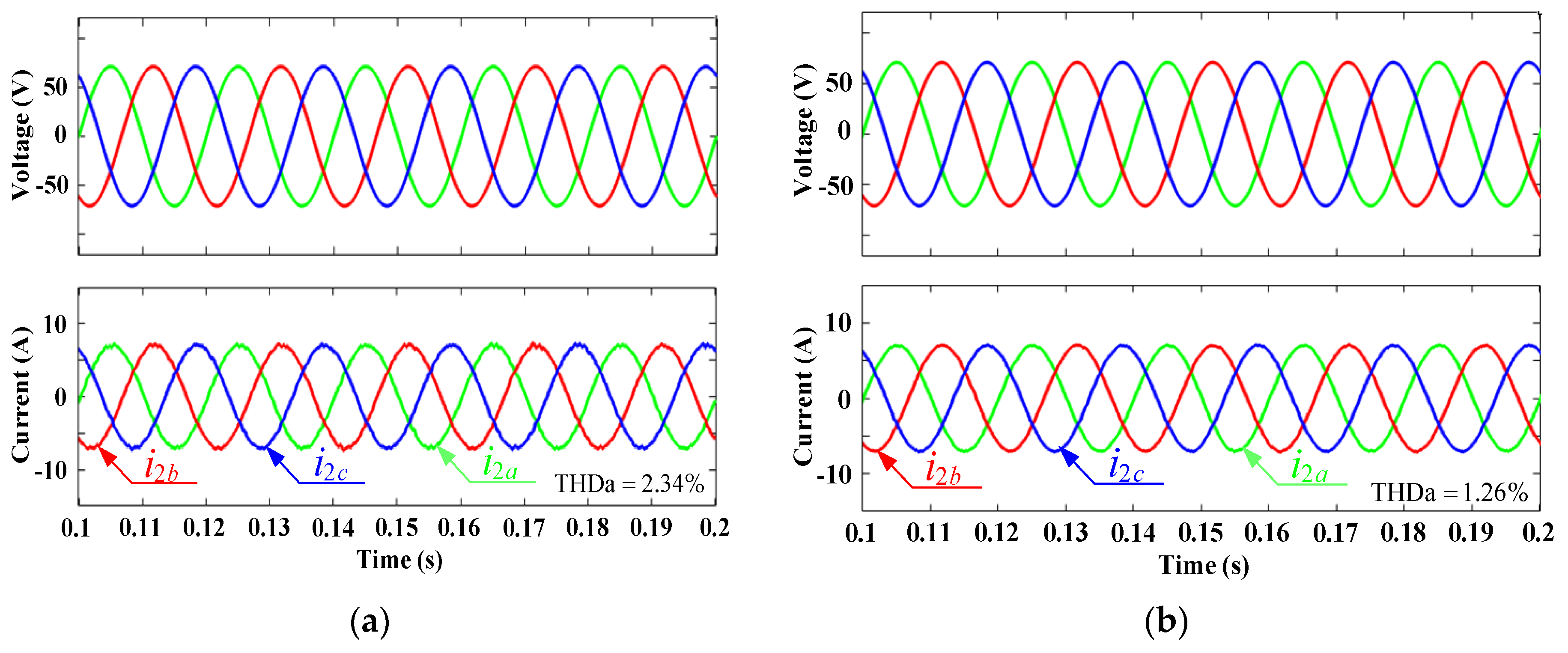
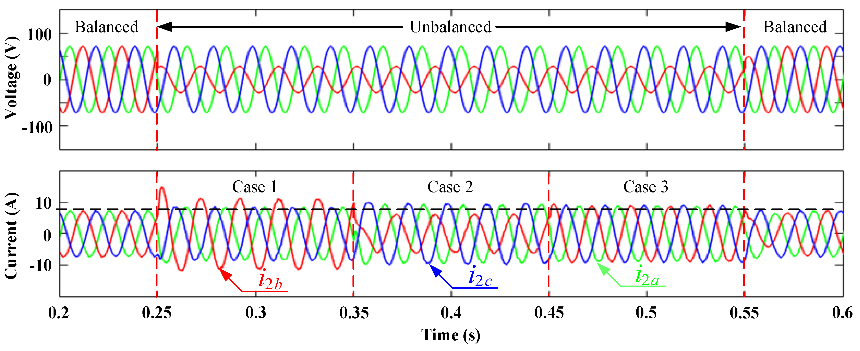
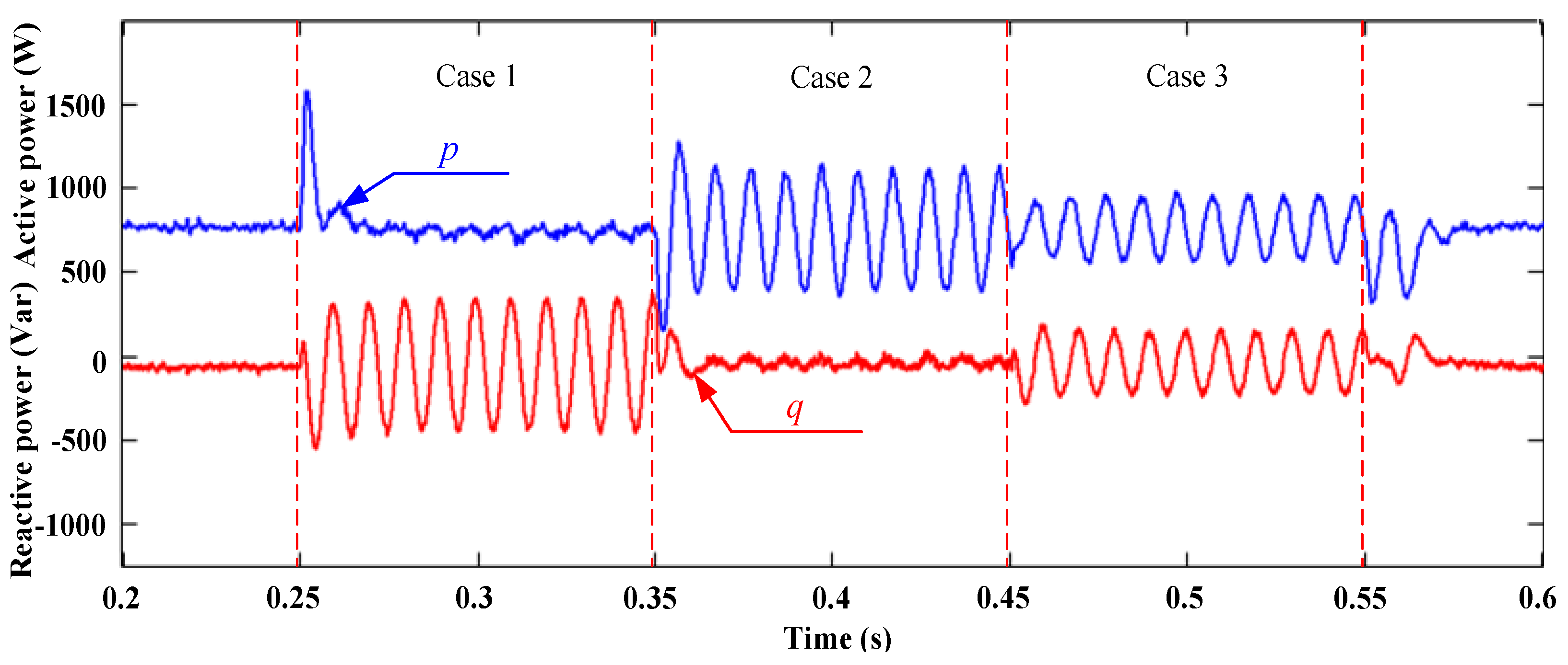
In order to verify the effectiveness of the proposed FCS-MPC strategy, the simulation test is carried out in MATLAB/Simulink. The system variables and parameters are listed as follows. The dc-side voltage is 150 V, the three-phase grid voltage is 50 V (RMS) and the rated power is 750 W. When the three-phase grid voltage falls into unbalance, b-phase voltage dips to 20 V (RMS) in this paper. The sampling frequency/sampling time is 25 kHz/40 μs. The inverter-side inductance is 2.4 mH, the grid-side inductance is 1.2 mH, and the filtering capacitor is 6 μF. The simulation results are shown in Figure 4, Figure 5, Figure 6, Figure 7 and Figure 8, respectively.
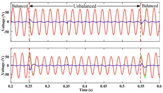
Figure 4.
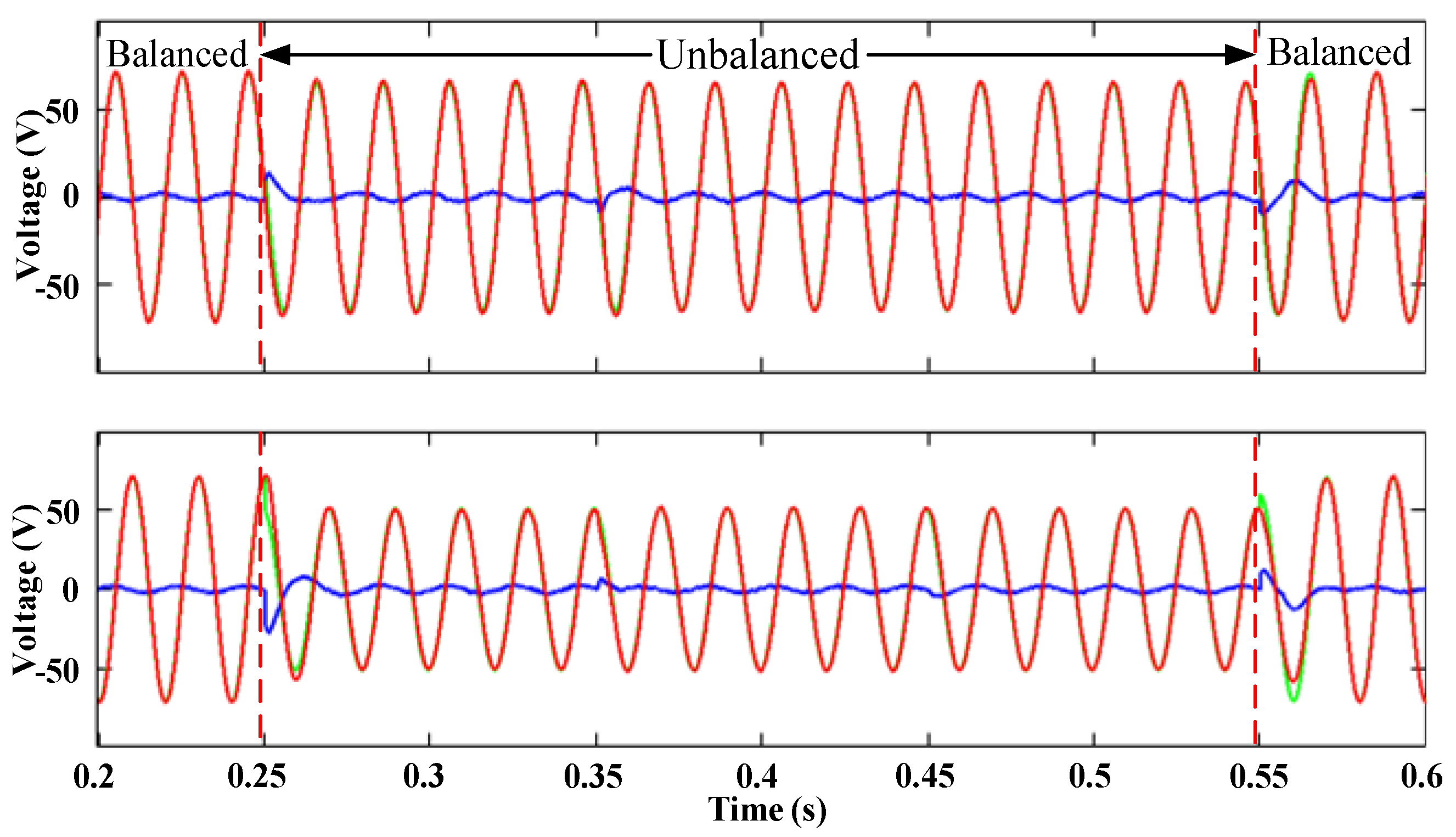
Simulated comparisons between measurements and estimations for the grid voltage in the αβ reference system (red—measurements, green—estimations, blue—errors).
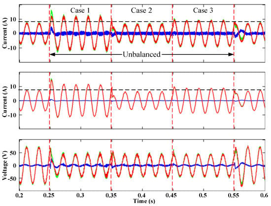
Figure 5.
Simulated comparisons between measurements and estimations for the state variables in b-phase (red—measurements, green—estimations, blue—errors); top—inverter-side current; middle—grid-injected current; bottom—capacitor voltage.
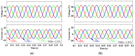
Figure 6.
The simulated performance comparison results between (a) the proposed control method and (b) the FCS-MPC with full status measurements.
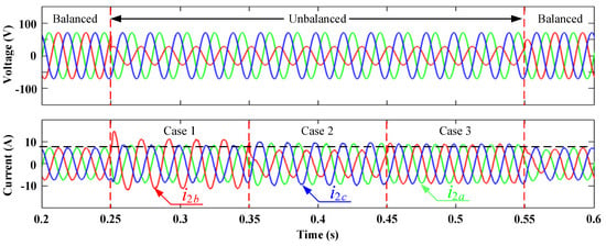
Figure 7.
Simulated grid voltage and grid-injected current under unbalanced grid voltage condition in three cases.
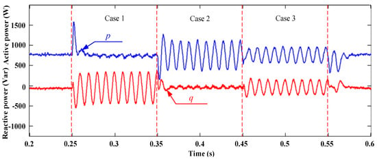
Figure 8.
Simulated results of the active power and reactive power under the unbalanced grid voltage condition in three cases.
Figure 4 shows the simulation results of the measured grid voltages, the estimated grid voltages, and their errors in the αβ stationary reference system, where the estimations are obtained by GVO. Figure 5 displays the simulation results of the three measured state variables and their estimations in b-phase, as well as the errors between measurements and estimations, where these estimations are calculated by the Luenberger observer. Additionally, the performance of the GVO and Luenberger observer is verified in cases 1, 2, and 3, respectively. It is worth noting that for all measured signals in this paper, including the grid voltage, the grid-injected current, the capacitor voltage, and the inverter-side current, only the grid-injected currents are applied for the GVO and Luenberger observer estimations. The other measured signals are only used for comparisons with the observation results.
It can be seen from Figure 4 that the observations of the grid voltage in α-axis and β-axis are both consistent with the measurements, and the errors of them under balanced and unbalanced grid voltages are both relatively small, which can be acceptable. Hence, the design of GVO is successful and effective. Since the reference of the grid-injected currents is variable for the different control targets under the unbalanced grid voltage, we can find that the amplitudes of the inverter-side currents and grid-injected currents vary with the change of three cases in Figure 5, where the dashed line expresses the amplitude of these two currents under the balanced grid voltages, and, the estimations of these two currents can track the measurements accurately. Additionally, the observed capacitor voltage also can follow the measured signal exactly, even under the unbalanced grid voltage condition. Consequently, the conclusion we can draw is that the estimations of the inverter-side currents, grid-injected currents, capacitor voltages, and grid voltages can replace the measurements and at least six sensors can be saved. Additionally, the effectiveness of the proposed FCS-MPC strategy for decreasing the number of sensors is preliminarily verified.
To further verify the effectiveness of the proposed FCS-MPC scheme, the performance comparison results between the proposed control method and the FCS-MPC with full status measurements are displayed in Figure 6. It can be seen that. Compared with the FCS-MPC with full status measurements, the quality of the grid-injected current of the proposed control method declines a little; however, it still can meet the harmonic standard of IEEE (the THD of the grid-injected current does not exceed 5%). Note that, compared with the FCS-MPC with full status measurements, at least six sensors can be saved for the proposed method.
Figure 7 shows the simulation results of the grid voltages and grid-injected currents under balanced and unbalanced grid voltages. The top of Figure 7 depicts that the grid voltages vary from balanced to unbalanced at 0.25 s, and then back to balanced at 0.55 s. In order to achieve grid synchronization and ensure the maximum energy injected into the grid, Q* is set to zero in this paper. Hence, based on Equations (29), (31), and (33), the references of the grid-injected currents can be calculated. The bottom of Figure 7 reveals the performance of the grid-injected currents under the unbalanced grid voltages by utilizing the proposed FCS-MPC strategy based on three different control targets. Figure 8 represents the simulation results of the active power and reactive power under the balanced and unbalanced grid voltages. It can be seen from Figure 7 that the three-phase grid-injected currents are sinusoidal but unbalanced in case 1 and case 2; however, the grid-injected currents are balanced and sinusoidal in case 3. For Figure 8, we found that the double frequency ripples of active power are eliminated in case 1, the double frequency ripples of reactive power are eliminated in case 2, and the double frequency ripples of both the active and reactive power exist in case 3, which is in agreement with the theoretical analysis described in Table 2. Therefore, according to Figure 4, Figure 5, Figure 6, Figure 7 and Figure 8, it can be verified that the proposed FCS-MPC strategy with merely grid-injected current sensors is effective, and it can obtain good performance of the grid-injected currents even under the unbalanced grid voltage condition.
6. Experimental Results
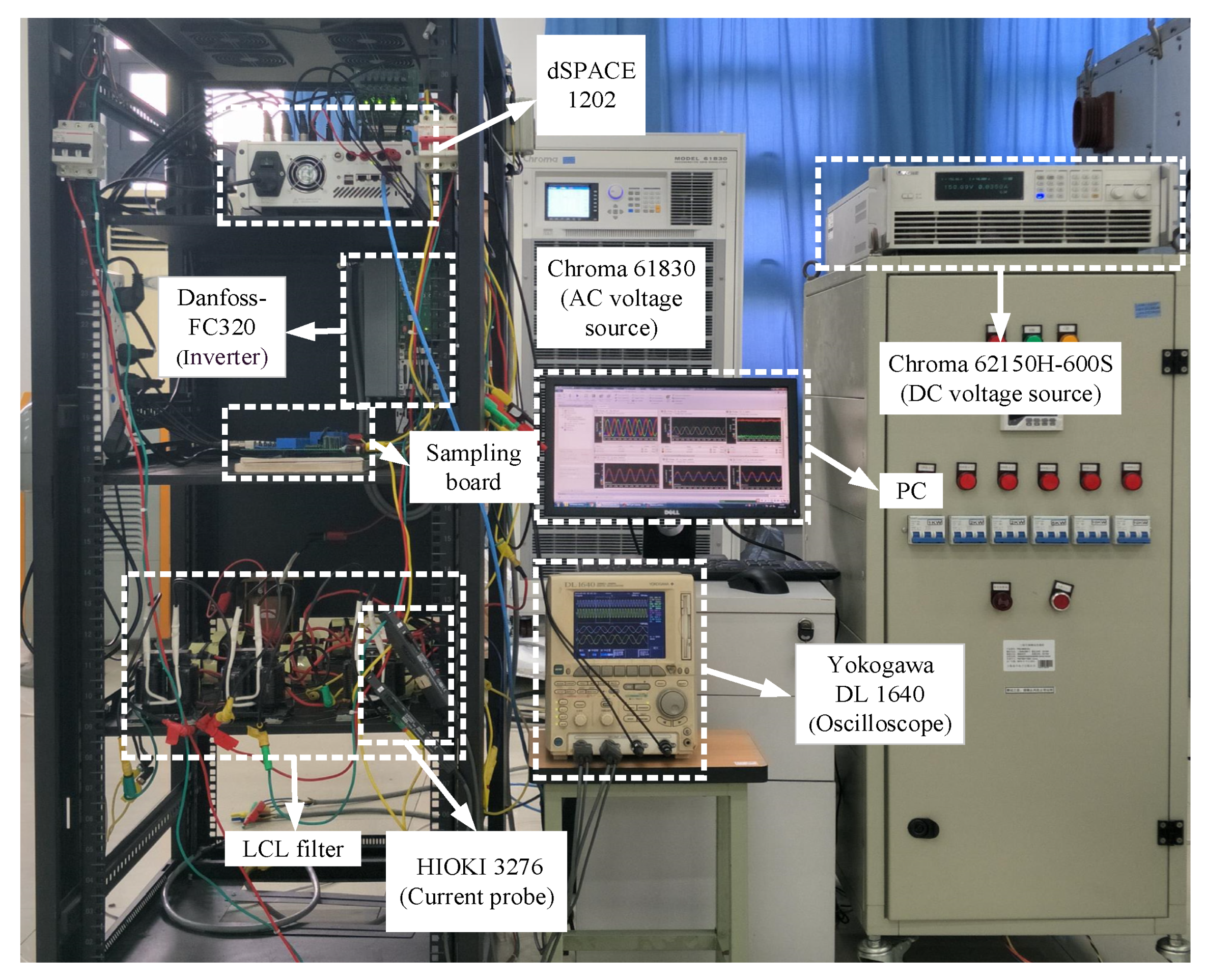
To further verify the effectiveness of the proposed FCS-MPC strategy, the laboratory test-rig depicted in Figure 9 is established. The experimental parameters were the same as the simulation ones. The programmable ac source (Chroma 61830) is utilized to simulate the balanced and unbalanced grid voltage condition. The power stage consists of a two-level voltage-source inverter (Danfoss-FC320) with a dc-link voltage provided by Chroma 62150 H-600S DC power supply. The digital control algorithm is implemented in dSPACE 1202 platform, where a control desk project is established to regulate control parameters and reference values, as well as display the experimental results which cannot be probed by the Yokogawa DL 1640 digital oscilloscope assembled with two current probes HIOKI 3276, including the inverter-side currents, grid-injected currents, capacitor voltages, grid voltages, active power, and reactive power in this paper.
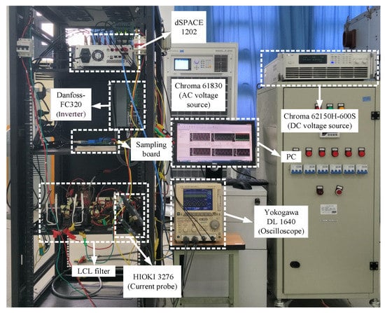
Figure 9.
The experimental test setup.
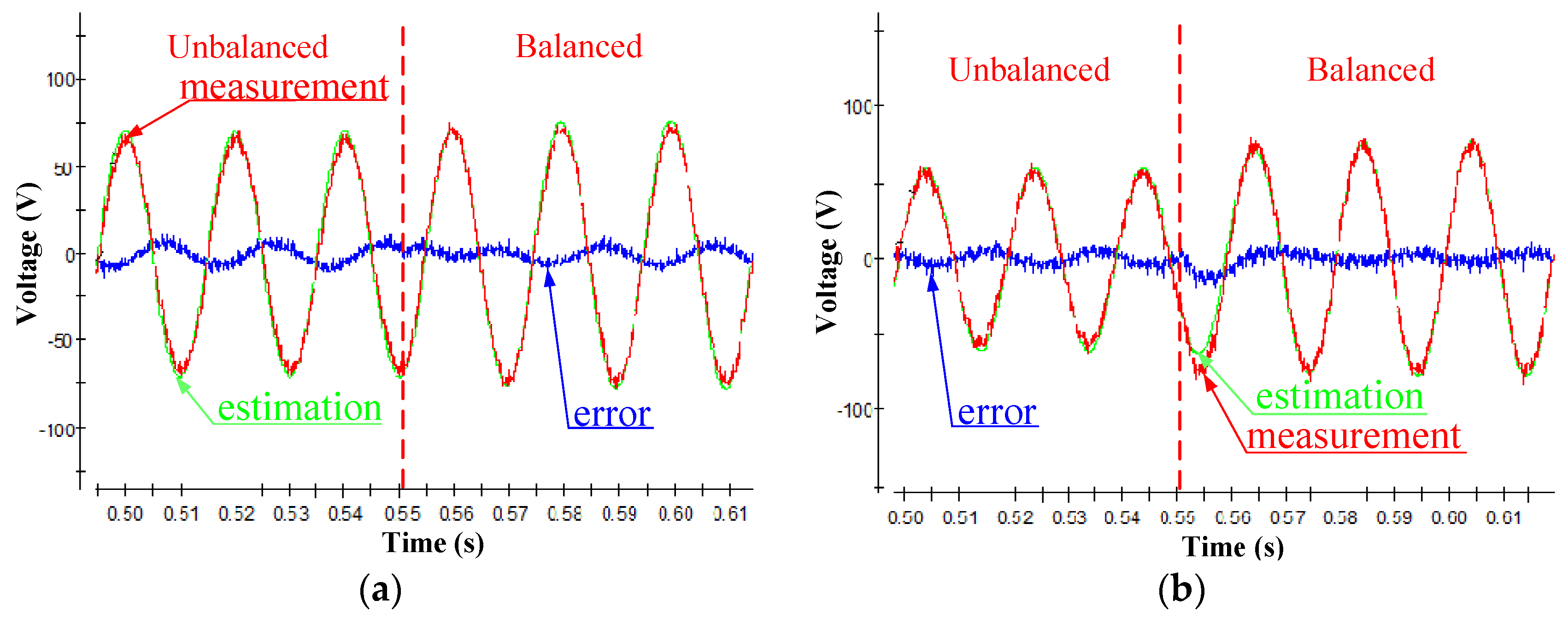
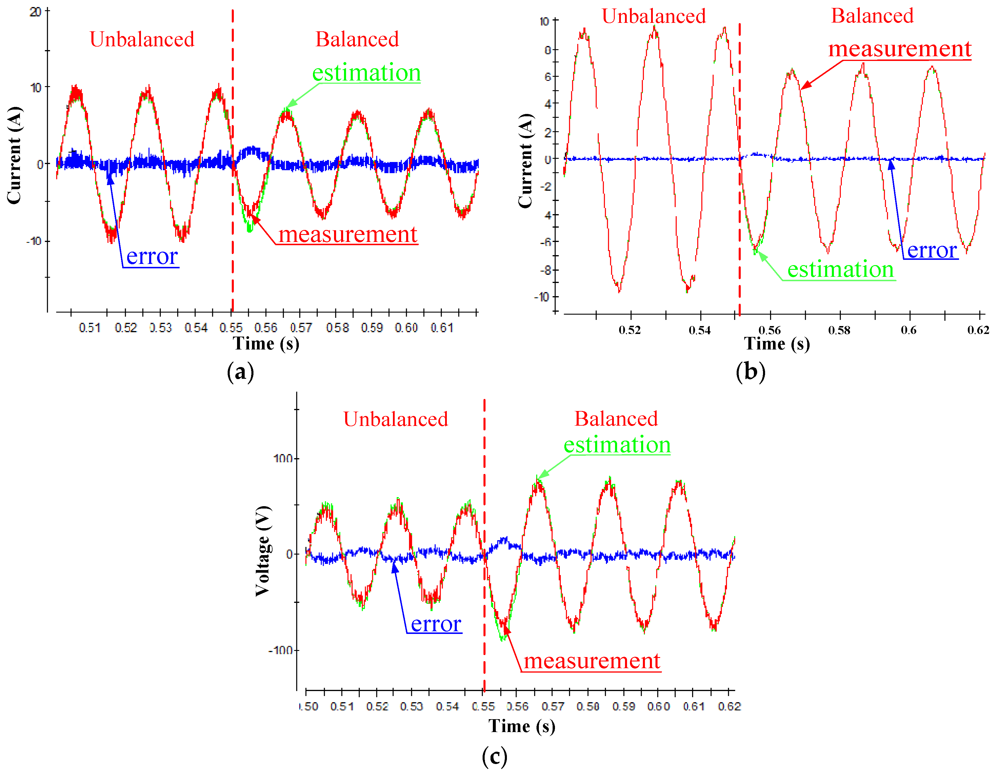
Figure 10 displays the experimental comparisons between measurements and estimations for the grid voltage in α-axis and β-axis, respectively, when grid voltage varies from unbalanced to balanced based on case 1. Figure 11 shows the experimental comparisons between measurements and estimations for the state variables in b-phase when grid voltage varies from unbalanced to balanced based on case 1. In Figure 10 and Figure 11, the red line expresses the measurement, the green line denotes the estimation, and the blue line represents their error. Additionally, it can be found that the observations track the measurements accurately both in steady and dynamic states, reflecting the effectiveness of the GVO and Luenberger observer. Therefore, the sensors of inverter-side current, capacitor voltage, and grid voltage can be saved by taking the observations instead of measurements into the FCS-MPC algorithm. The experimental comparisons based on case 2 and case 3 also can be obtained, and the effects of track are similar to the case 1, thus it is not shown in this paper. It should be noticed that, for all measurements, except for the grid-injected currents, the other measured signals are merely utilized for comparisons with the estimated results.
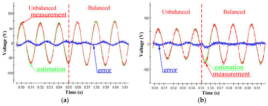
Figure 10.
Experimental comparisons between measurements and estimations for the grid voltage in the αβ reference system when grid voltage varies from unbalanced to balanced in case 1: (a) Grid voltage in α-axis, (b) grid voltage in β-axis.
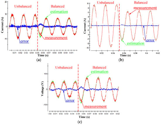
Figure 11.
Experimental comparisons between measurements and estimations for the state variables in b-phase when grid voltage varies from unbalanced to balanced in case 1: (a) Inverter-side current, (b) grid-injected current, (c) capacitor voltage.
Figure 12 depicts the experimental performance comparison results between the proposed control method and the FCS-MPC with full status measurements. Although the THD of the grid-injected current by adopting the proposed control method is higher than the one using the FCS-MPC with full status measurements, the difference between these two THD values of grid-injected current is not so large, where they both meet the harmonic standard of IEEE (the THD of grid-injected current does not exceed 5%). Therefore, the effectiveness of the proposed control method is verified.

Figure 12.
The experimental performance comparison results between (a) the proposed control method and (b) the FCS-MPC with full status measurements.
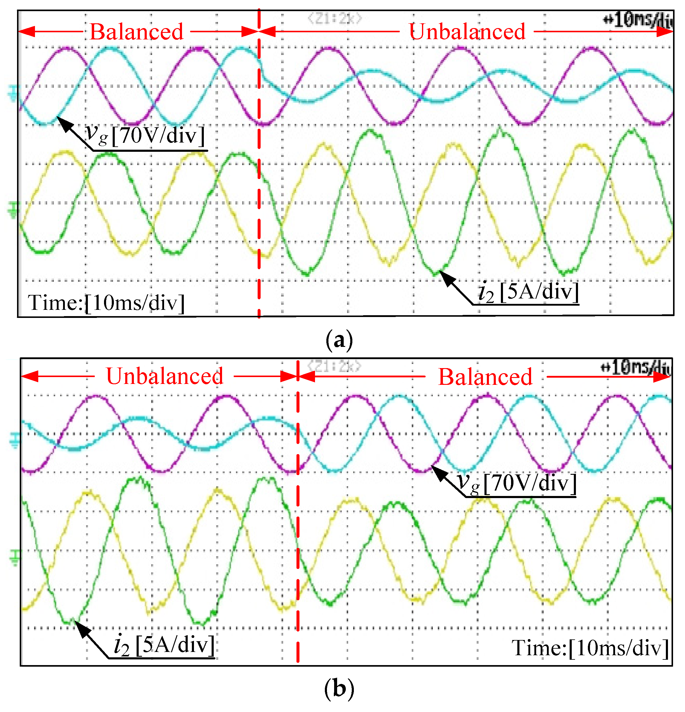
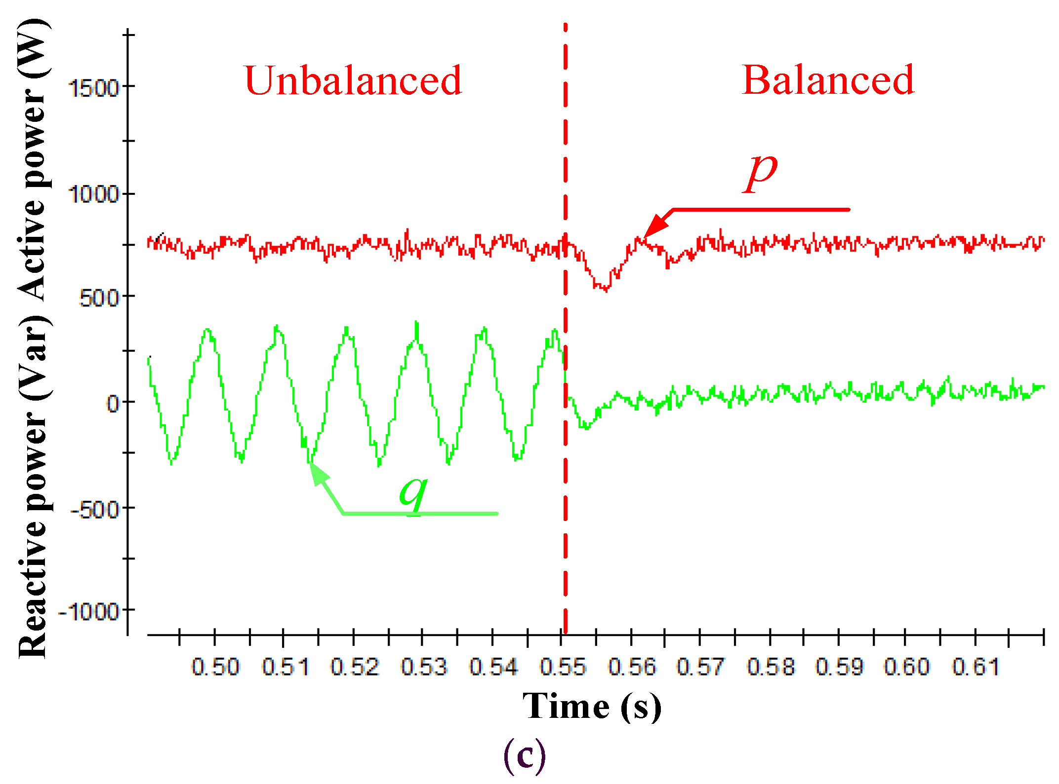
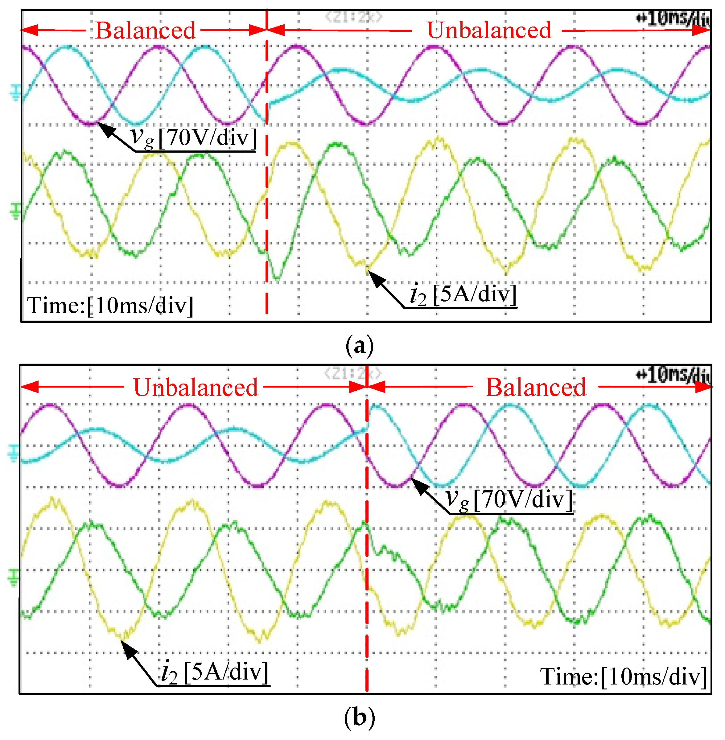
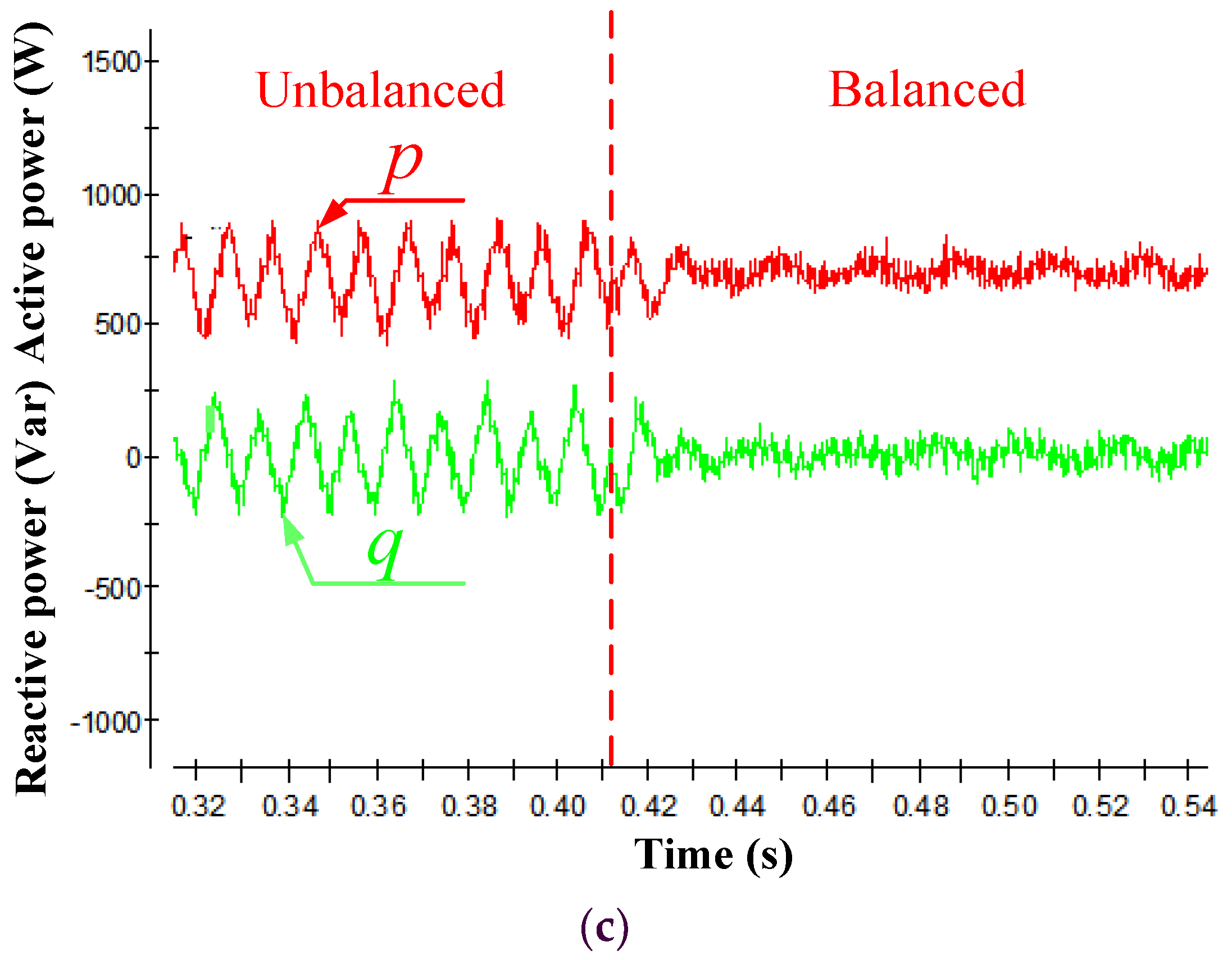
Figure 13, Figure 14 and Figure 15 show the experimental results of grid-injected currents, active and reactive power by utilizing the proposed FCS-MPC scheme based on three different control targets, which are adopted to eliminate the negative effects caused by the unbalanced grid voltage, respectively. Due to the limitation of the experimental device, only a-phase and b-phase voltages and currents are measured. It can be observed from Figure 13 that the grid-injected currents are sinusoidal but unbalanced (the current in b-phase is largest, while the amplitude of currents in a-phase and c-phase are same) in the steady states, and the dynamic performance is good when the grid voltages vary from balanced to unbalanced and then back to balanced. Note that further optimization in the research is possible by increasing the sampling frequency, but it is not the subject of this paper, and the double frequency ripples of the active power are eliminated, while the ripples of the reactive power still exist under the unbalanced grid voltage. Hence, the experimental results are in agreement with the theoretical analysis of case 1.
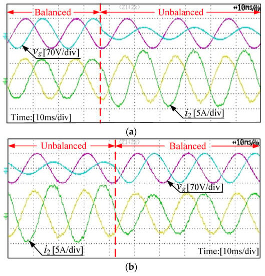
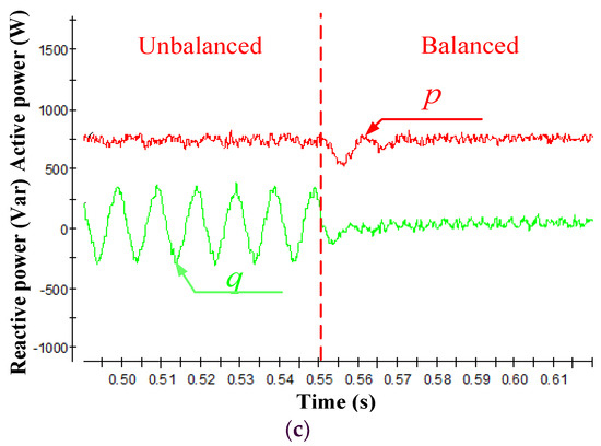
Figure 13.
Experimental results of (a) grid-injected current when grid voltage varies from balanced to unbalanced, (b) grid-injected current when grid voltage varies from unbalanced to balanced, and (c) active and reactive power when grid voltage varies from unbalanced to balanced in case 1.
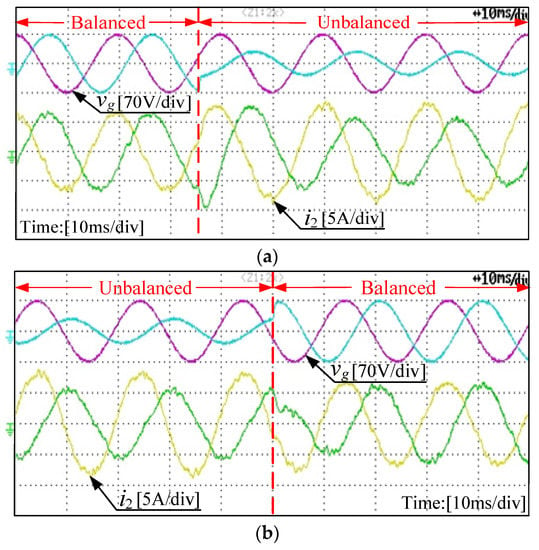
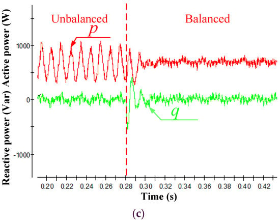
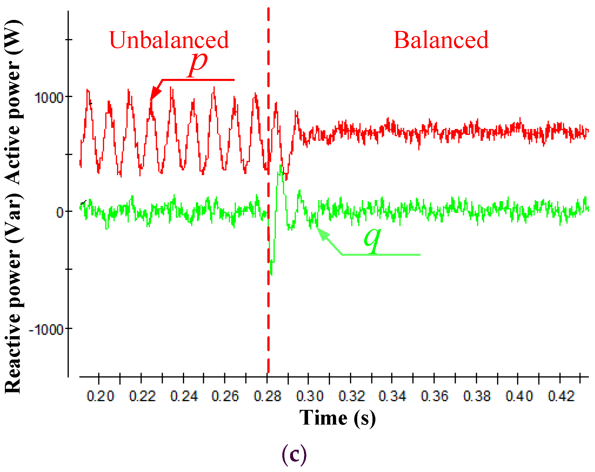
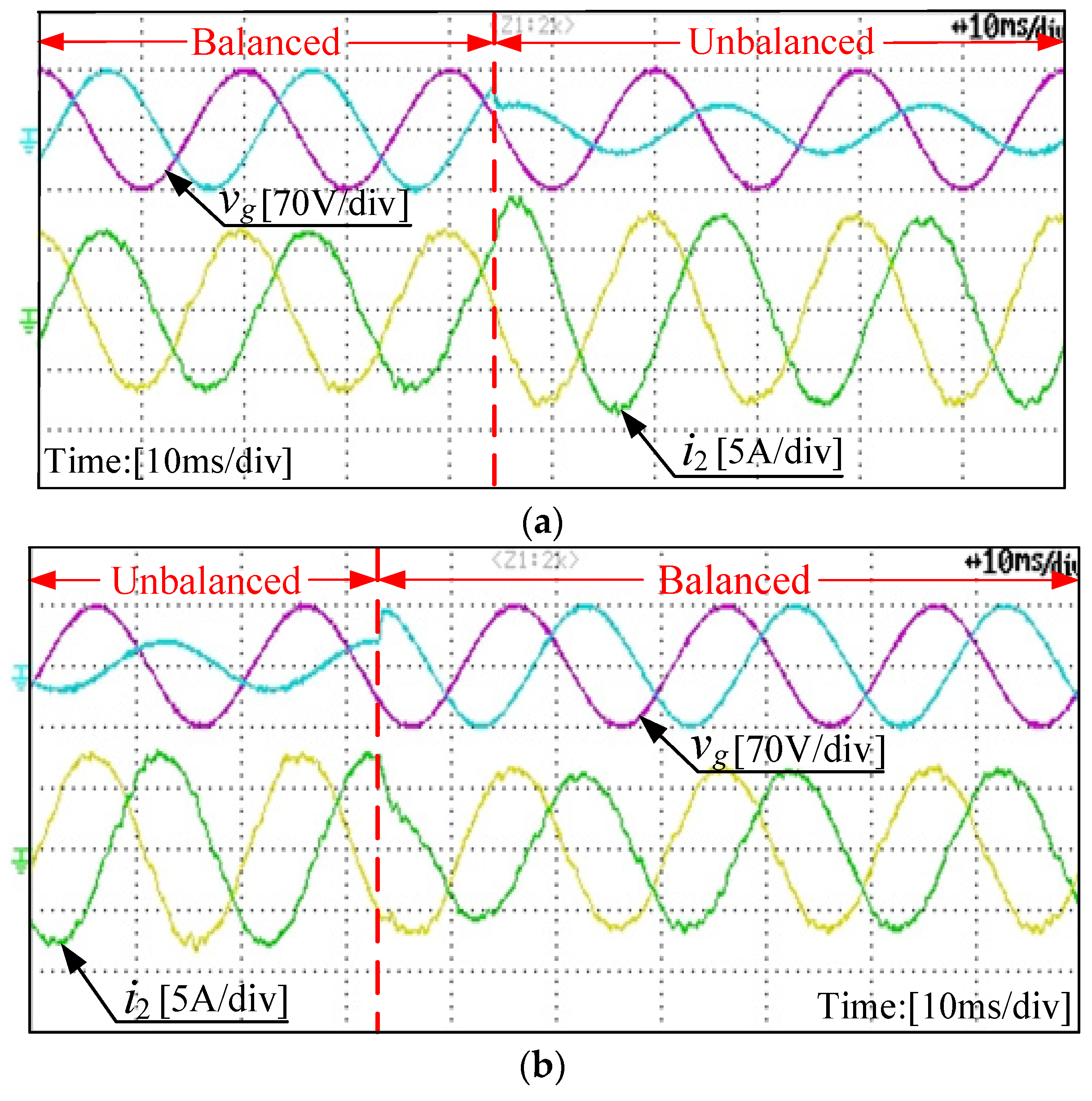
Figure 14.
Experimental results of (a) grid-injected current when grid voltage varies from balanced to unbalanced, (b) grid-injected current when grid voltage varies from unbalanced to balanced, and (c) active and reactive power when grid voltage varies from unbalanced to balanced in case 2.
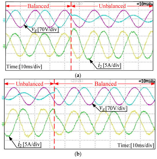
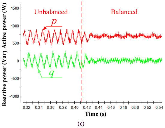
Figure 15.
Experimental results of (a) grid-injected current when grid voltage varies from balanced to unbalanced, (b) grid-injected current when grid voltage varies from unbalanced to balanced, and (c) active and reactive power when grid voltage varies from unbalanced to balanced in case 3.
As demonstrated in Figure 14, the performance of the grid-injected currents are acceptable both in steady (the current in b-phase is smallest, while the amplitude of currents in a-phase and c-phase are same) and dynamic states, and the double frequency ripples of the reactive power are eliminated, while the active power ripples still exist under the unbalanced grid voltage. Consequently, the experimental results verify the correctness of the theory of case 2.
Figure 15 displays the sinusoidal grid-injected currents with different amplitudes under the balanced grid voltage and the unbalanced grid voltage. However, it can be found that the currents are balanced whether three-phase grid voltages are balanced or not, and the transient performance is good when the grid voltages change from balanced to unbalanced and then back to balanced. Furthermore, the double frequency ripples of the active and reactive power are not removed under the unbalanced grid voltages. These performances are also consistent with the theoretical analysis of case 3.
According to the simulation and experimental results shown above, it can be found that the proposed FCS-MPC strategy with merely grid-injected current sensors can work well whether the grid voltages are balanced or not.
7. Conclusions
In this paper, a novel FCS-MPC strategy with full status observations based on GVO and Luenberger observer is proposed for the LCL-filtered grid-tied inverter under the unbalanced grid voltage condition. A step-by-step design procedure of the proposed control scheme is described in detail. The simulation model and experimental platform are established to verify the performance of proposed control method, where the three different reference cases of the grid-injected currents in the proposed cost function are analyzed. By theoretical analysis, simulation, and experimental verification, the following conclusions can be drawn:
- By utilizing the proposed control algorithm, the errors between observations and measurements are small enough under both balanced and unbalanced grid voltages, and the observations have a good dynamic response. Therefore, these observations can replace the measurements used in the control.
- Under the unbalanced grid voltage condition, the proposed FCS-MPC strategy obtains the satisfactory performance in both the steady and dynamic states for three different control targets. Note that only the grid-injected currents are measured.
Author Contributions
Conceptualization, X.C. and W.W.; methodology, X.C., W.W. and N.G.; software, X.C. and J.L.; validation, X.C., and N.G.; formal analysis, X.C. and W.W.; investigation, X.C.; resources, W.W.; data curation, X.C.; writing—original draft preparation, X.C. and W.W.; writing—review and editing, W.W., N.G., H.S.-H.C. and F.B.; visualization, X.C.; supervision, W.W., N.G., H.S.-H.C. and F.B.; project administration, W.W.; funding acquisition, W.W.
Funding
This work was funded in part by the National Natural Science Foundation of China, grant number 51877130 and 51561165013, and in part by the Shanghai Shuguang Talent Program, grant number 14SG43.
Conflicts of Interest
The authors declare no conflicts of interest.
References
- Blaabjerg, F.; Yang, Y.; Yang, D.; Wang, X. Distributed Power-Generation Systems and Protection. Proc. IEEE 2017, 105, 1311–1331. [Google Scholar] [CrossRef]
- Kouro, S.; Leon, J.I.; Vinnikov, D.; Franquelo, L.G. Grid-Connected Photovoltaic Systems: An Overview of Recent Research and Emerging PV Converter Technology. IEEE Ind. Electron. Mag. 2015, 9, 47–61. [Google Scholar] [CrossRef]
- Wu, W.; Liu, Y.; He, Y.; Chung, H.S.; Liserre, M.; Blaabjerg, F. Damping Methods for Resonances Caused by LCL-Filter-Based Current-Controlled Grid-Tied Power Inverters: An Overview. IEEE Trans. Ind. Electron. 2017, 64, 7402–7413. [Google Scholar] [CrossRef]
- Liu, Y.; Wu, W.; He, Y.; Lin, Z.; Blaabjerg, F.; Chung, H.S. An Efficient and Robust Hybrid Damper for LCL-or LLCL-Based Grid-Tied Inverter with Strong Grid-Side Harmonic Voltage Effect Rejection. IEEE Trans. Ind. Electron. 2016, 63, 926–936. [Google Scholar] [CrossRef]
- Ahmed, A.; Koh, B.K.; Lee, Y.I. A Comparison of Finite Control Set and Continuous Control Set Model Predictive Control Schemes for Speed Control of Induction Motors. IEEE Trans. Ind. Inform. 2018, 14, 1334–1346. [Google Scholar] [CrossRef]
- Vieira, R.P.; Martins, L.T.; Massing, J.R.; Stefanello, M. Sliding Mode Controller in a Multiloop Framework for a Grid-Connected VSI with LCL Filter. IEEE Trans. Ind. Electron. 2018, 65, 4714–4723. [Google Scholar] [CrossRef]
- Mu, X.; Wang, J.; Wu, W.; Blaabjerg, F. A Modified Multifrequency Passivity-Based Control for Shunt Active Power Filter with Model-Parameter-Adaptive Capability. IEEE Trans. Ind. Electron. 2018, 65, 760–769. [Google Scholar] [CrossRef]
- Kouro, S.; Cortes, P.; Vargas, R.; Ammann, U.; Rodriguez, J. Model Predictive Control—A Simple and Powerful Method to Control Power Converters. IEEE Trans. Ind. Electron. 2009, 56, 1826–1838. [Google Scholar] [CrossRef]
- Rodriguez, J.; Kazmierkowski, M.P.; Espinoza, J.R.; Zanchetta, P.; Abu-Rub, H.; Young, H.A.; Rojas, C.A. State of the Art of Finite Control Set Model Predictive Control in Power Electronics. IEEE Trans. Ind. Inform. 2013, 9, 1003–1016. [Google Scholar] [CrossRef]
- Yaramasu, V.; Rivera, M.; Wu, B.; Rodriguez, J. Model Predictive Current Control of Two-Level Four-Leg Inverters—Part I: Concept, Algorithm, and Simulation Analysis. IEEE Trans. Power Electron. 2013, 28, 3459–3468. [Google Scholar] [CrossRef]
- Xia, C.; Liu, T.; Shi, T.; Song, Z. A Simplified Finite-Control-Set Model-Predictive Control for Power Converters. IEEE Trans. Ind. Inform. 2014, 10, 991–1002. [Google Scholar]
- Falkowski, P.; Sikorski, A. Finite Control Set Model Predictive Control for Grid-Connected AC–DC Converters with LCL Filter. IEEE Trans. Ind. Electron. 2018, 65, 2844–2852. [Google Scholar] [CrossRef]
- Liang, J.; Wang, H.; Yan, Z. Grid Voltage Sensorless Model based Predictive Power Control of PWM Rectifiers Based on Sliding Mode Virtual Flux Observer. IEEE Access 2019, 7, 24007–24016. [Google Scholar] [CrossRef]
- Zhang, H.; Zhu, X.; Shi, J.; Tan, L.; Zhang, C.; Hu, K. Study on PWM Rectifier Without Grid Voltage Sensor Based on Virtual Flux Delay Compensation Algorithm. IEEE Trans. Power Electron. 2019, 34, 849–862. [Google Scholar] [CrossRef]
- Yoon, S.; Lai, N.; Kim, K. A Systematic Controller Design for a Grid-Connected Inverter with LCL Filter Using a Discrete-Time Integral State Feedback Control and State Observer. Energies 2018, 11, 437. [Google Scholar] [CrossRef]
- Kukkola, J.; Hinkkanen, M. State Observer for Grid-Voltage Sensorless Control of a Converter Equipped with an LCL Filter: Direct Discrete-Time Design. IEEE Trans. Ind. Appl. 2016, 52, 3133–3145. [Google Scholar] [CrossRef]
- Yang, H.; Zhang, Y.; Liang, J.; Liu, J.; Zhang, N.; Walker, P.D. Robust Deadbeat Predictive Power Control with a Discrete-Time Disturbance Observer for PWM Rectifiers Under Unbalanced Grid Conditions. IEEE Trans. Power Electron. 2019, 34, 287–300. [Google Scholar] [CrossRef]
- Camacho, A.; Castilla, M.; Miret, J.; Borrell, A.; de Vicuña, L.G. Active and Reactive Power Strategies with Peak Current Limitation for Distributed Generation Inverters During Unbalanced Grid Faults. IEEE Trans. Ind. Electron. 2015, 62, 1515–1525. [Google Scholar] [CrossRef]
- Zheng, X.; Wang, C.; Pang, S. Injecting positive-sequence current virtual synchronous generator control under unbalanced grid. IET Renew. Power Gener. 2019, 13, 165–170. [Google Scholar] [CrossRef]
- Suul, J.A.; Luna, A.; Rodriguez, P.; Undeland, T. Voltage-Sensor-Less Synchronization to Unbalanced Grids by Frequency-Adaptive Virtual Flux Estimation. IEEE Trans. Ind. Electron. 2012, 59, 2910–2923. [Google Scholar] [CrossRef]
- Yang, H.; Zhang, Y.; Liang, J.; Gao, J.; Walker, P.D.; Zhang, N. Sliding-Mode Observer Based Voltage-Sensorless Model Predictive Power Control of PWM Rectifier Under Unbalanced Grid Conditions. IEEE Trans. Ind. Electron. 2018, 65, 5550–5560. [Google Scholar] [CrossRef]
- Rodriguez, P.; Pou, J.; Bergas, J.; Candela, J.I.; Burgos, R.P.; Boroyevich, D. Decoupled Double Synchronous Reference Frame PLL for Power Converters Control. IEEE Trans. Power Electron. 2007, 22, 584–592. [Google Scholar] [CrossRef]
- Svensson, J.; Bongiorno, M.; Sannino, A. Practical Implementation of Delayed Signal Cancellation Method for Phase-Sequence Separation. IEEE Trans. Power Deliv. 2007, 22, 18–26. [Google Scholar] [CrossRef]
- Zhou, D.; Tu, P.; Tang, Y. Multivector Model Predictive Power Control of Three-Phase Rectifiers with Reduced Power Ripples Under Nonideal Grid Conditions. IEEE Trans. Ind. Electron. 2018, 65, 6850–6859. [Google Scholar] [CrossRef]
- Ma, K.; Chen, W.; Liserre, M.; Blaabjerg, F. Power Controllability of a Three-Phase Converter with an Unbalanced AC Source. IEEE Trans. Power Electron. 2015, 30, 1591–1604. [Google Scholar] [CrossRef]
- Chen, X.; Wu, W.; Gao, N.; He, Y.; Chung, H.S.; Blaabjerg, F. Finite Control Set Model Predictive Control for LCL-Filter-Based Grid-Tied Inverter with Computational Delay Compensation. In Proceedings of the 2018 IEEE International Power Electronics and Application Conference and Exposition (PEAC), Shenzhen, China, 4–7 November 2018; pp. 1–6. [Google Scholar]
- Panten, N.; Hoffmann, N.; Fuchs, F.W. Finite Control Set Model Predictive Current Control for Grid-Connected Voltage-Source Converters with LCL Filters: A Study Based on Different State Feedbacks. IEEE Trans. Power Electron. 2016, 31, 5189–5200. [Google Scholar] [CrossRef]
- Cortes, P.; Kouro, S.; Rocca, B.L.; Vargas, R.; Rodriguez, J.; Leon, J.I.; Vazquez, S.; Franquelo, L.G. Guidelines for weighting factors design in Model Predictive Control of power converters and drives. In Proceedings of the 2009 IEEE International Conference on Industrial Technology, Gippsland, Australia, 10–13 February 2009; pp. 1–7. [Google Scholar]
© 2019 by the authors. Licensee MDPI, Basel, Switzerland. This article is an open access article distributed under the terms and conditions of the Creative Commons Attribution (CC BY) license (http://creativecommons.org/licenses/by/4.0/).

