Article

Performance Analysis of a Flexi-Fuel Turbine-Combined Free-Piston Engine Generator

1
Sir Joseph Swan Centre for Energy Research, Newcastle University, Newcastle upon Tyne, NE1 7RU, UK
2
Beijing Institute of Technology, School of Mechanical Engineering, Beijing 100081, China
*
Author to whom correspondence should be addressed.
Energies 2019, 12(14), 2657; https://doi.org/10.3390/en12142657
Submission received: 14 May 2019 / Revised: 5 July 2019 / Accepted: 8 July 2019 / Published: 11 July 2019
(This article belongs to the Section I: Energy Fundamentals and Conversion)

Abstract

:
The turbine-combined free-piston engine generator (TCFPEG) is a hybrid machine, generating both mechanical work from the gas turbine and electricity from the linear electric generator for battery charging. In the present study, the system performance of the designed TCFPEG system is predicted using a validated numerical model. A parametric analysis is undertaken based on the influence of the engine load, valve timing, the number of linear generators adopted, and different fuels on the system performance. It is found that when linear electric generators are connected with the free-piston gas turbine, the bottom dead centre, the peak piston velocity, and engine operation frequency are all reduced. Very minimal difference on the in-cylinder pressure and the compressor pressure is observed, while the peak pressure in the bounce chamber is reduced. When coupled with a linear electric generator, the system efficiency can be improved to nearly 50% by optimising engine load and the number of the linear generators adopted in the TCFPEG system. The system is able to be operated with different fuels as the piston is not limited by a mechanical system; the output power and system efficiency are highest when hydrogen is used as the fuel.

Graphical Abstract

1. Introduction

The free-piston engine (FPE) is a linear engine, which eliminates the crankshaft system in the conventional reciprocating engines, and the piston assembly has a free and linear motion between its two dead centres [1]. The FPE was first proposed around 1930, and it is known to have greater thermal efficiency than a conventional engine of similar size [2]. During the operation of the FPE, the high pressure exhaust gas after combustion pushes the piston assembly backwards, and a proper load is required to convert the mechanical energy of the piston assembly for the usage of the target application [3].
Previously reported FPE applications mainly include a free-piston engine gas turbine that uses the exhaust gas from the FPE to drive a gas turbine to generate mechanical power, a hydraulic free-piston engine that outputs hydraulic power, and a free-piston engine generator that generates electricity [4,5,6,7]. The main characteristics and a review of each FPE application mentioned above will be summarised in this section.

1.1. Free-Piston Engine (FPE) Powered Gas Turbines

The SIGMA GS-34 was designed and built in the 1940s. It was a diesel-fuelled, opposed piston FPE configuration, which drives a power gas turbine with the exhaust gas from the FPE. This has been the most successful FPE application, with over 300 units sold in Europe [8]. This device has become a popular prototype for followers due to its key advantages. For example, General Motor (GM) researcher Gregory Flynn reported 25,000 h of operation for the GS-34 in an effort to understand the physics behind this device. During the operation of the GS-34, when the injection rate was set at 5600 mg/cycle at 613 cycles per minute, the calculated brake thermal efficiency was 34.6% from a numerical analysis [8,9]. The engine brake thermal efficiency here is the ratio of the useful work produced by the turbine per cycle to the amount of fuel energy supplied per cycle that can be released in the combustion process. The exhaust flow of 3.62 kg/s at a temperature of 1033 K and pressure of 4.45 bar produces a turbine work of 850 kW [8].

1.2. Hydraulic Free-Piston Engine

The hydraulic free-piston engine (HFPE) combines the FPE with the incompressible working fluid, the force from which is approximately constant due to the constant discharge pressure [10,11]. The energy of the heat release process of an HFPE is almost directly converted into hydraulic energy, which is a non-rigid transmission and can use pulse pause modulation (PPM) of the piston frequency for the flow output control. The experimental results from a single piston HFPE exhibited that engine indicated efficiency could reach up to 50%. By varying the injection timings and exhaust gas recirculation rates, and by operating at higher compression ratios, lower soot & oxides of nitrogen emissions can be achieved [12].

1.3. Free-Piston Engine Generator

The free-piston engine generator (FPEG) combines FPE with a linear electric generator for utilisation within hybrid vehicles [13,14]. Combustion in the chambers of the FPE makes the piston assembly reciprocate, and the linear generator converts part of the mover’s mechanical energy into electricity [15]. It is relatively compact in size and generally of a high efficiency of up to 46%, at a power level of 23 kW [16]. FPEGs have been developed and successfully implemented by the German Aerospace Centre (DLR) [17], which could achieve an output of 25 kW at a frequency of 50 Hz [18,19]. Toyota Central R&D Labs Inc. similarly established an FPEG prototype (single-piston) that was found to be steady for a prolonged duration of time [20,21]. Several studies on dual piston FPEGs are cited in the works of [1,14,22,23,24].

1.4. Aims and Objectives

This work mainly focuses on opposed piston configuration, which consists of two single piston assemblies with a common combustion chamber. Therefore, each piston requires a bounce chamber as a gas spring to push the piston backward. The turbine-combined free-piston engine generator (TCFPEG) itself is a hybrid machine, generating both mechanical work from the gas turbine and electricity from the linear electric generator. By adjusting the power extraction ratio from the two devices, high thermal efficiencies can be expected over a broad range of speeds and loads.

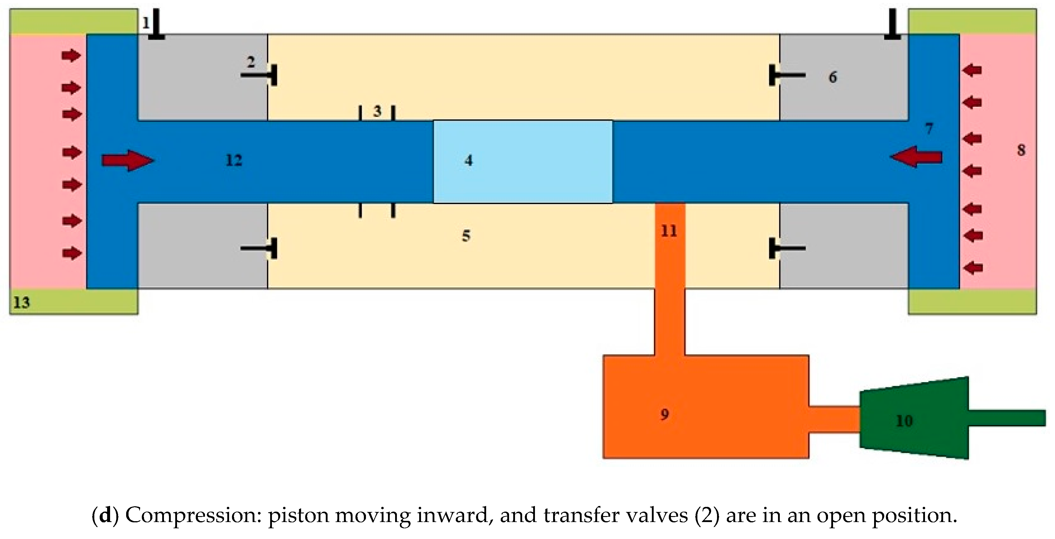
2. System Configuration

The schematic configuration of the designed turbine-combined free-piston engine generator system is shown in Figure 1.
This design is based on the TCFPEG engine, and it is similar to the SIGMA GS-34 system [8]. This is an opposed free-piston engine with the linear generators decoupled from the common combustion chamber (labelled 4) in the centre. It has two valves, namely an intake valve (labelled 1) for charge intake and a transfer valve (labelled 2) for the supply of compressed charge from the compression chamber (labelled 6) to the air-box (labelled 5). The system also has two ports called the intake port (labelled 3) for the flow of compressed charge from air-box to combustion chamber and the exhaust port (labelled 11) to expel burnt gases into the exhaust manifold (labelled 9). The turbine (labelled 10) is coupled to the exhaust manifold of an engine. The opposed pistons of the TCFPEG system are divided into air piston (labelled 7) and power piston (labelled 12). The power piston compresses the air–fuel mixture in the combustion chamber for combustion, and the air piston only compresses air in the compressor chamber and bounce chamber (labelled 8). The bounce chambers are located at both ends of the system and are filled with air to supply bouncing forces while being compressed. The air-box stores the compressed charge from the compressor chamber. The system is connected to linear generators (labelled 13), which generates electricity.
Figure 2 illustrates the working of the TCFPEG in detail. The working cycle of the TCFPEG can be divided into combustion, expansion/suction, scavenging/exhaust, and compression phases as shown in Figure 2a–d, respectively. The system works on the principle of a two-stroke internal combustion engine. Starting with the combustion phase, the compressed charge gets combusted in the combustion chamber (labelled 4), as depicted in Figure 2a. During this phase, all valves and ports of the system are in the closed position. As shown in Figure 2b, the combustion during the combustion phase produces elevated pressure, which pushes the two pistons outward. During this phase, the intake valve (labelled 1) opens, and fresh charge enters the compressor chamber.
As shown in Figure 2c, further outward movement of the piston opens the intake port (labelled 3) and the exhaust port (labelled 11). The fresh charge from the air-box enters into the combustion chamber through the intake port. This fresh charge then flows along with burnt gases to the exhaust manifold through the exhaust port. Figure 2d shows the compression phase. During this phase, the transfer valves are opened, and the energy accumulated in the bounce chamber pushes the pistons towards the combustion chamber. The fresh charge inside the compressor chambers gets compressed and delivered into the air-box through the transfer valves (labelled 2). The further movement of the pistons covers the intake and exhaust ports and compresses the charge in the combustion chamber, and the cycle repeats.
The linear electric machines are operated as a generator during the expansion process to produce electricity, then they are switched to a linear motor to act as active controllers for driving the pistons to the set dead centres. The design parameters of the TCFPEG system are listed in Table 1, which are in accordance with the parameters of the SIGMA GS-34 system.

3. Simulation Model and Validation

3.1. Mathematical Modelling

The dynamic equation for the forces acting on each piston is expressed in Equation 1, in accordance with Newton’s Second Law. Mechanical friction force, force from the linear electric machine, force from the in-cylinder gas, and inertia of the moving mass are the forces acting on the pistons.
F c + F c o m p + F b + F e + F f = m d 2 x d t 2   ,
where F c (unit: N) is the gas force from the combustion chamber; F c o m p (N) is the gas force from the compressor; F b (N) is the gas force from the bounce chamber; F e (N) is the force output from the linear electric machine—a parameter that is varied depending on whether the machine is operated in motoring or generation modes; F f (N) is the mechanical friction force; m   (kg) is the moving mass of the piston assembly with the mover of the electric machine,   x (m) is the mover displacement.
The in-cylinder gas was considered as an ideal gas in a closed system but parameterised for gas leakage past the pistons (blow-by) and heat transfer [25,26,27]. The analysis of the in-cylinder gas properties during the compression and expansion phases of the cycle is based on a zero-dimensional thermodynamic approach. More details about the FPEG model can be found in our previous publications [25,26,27]. Imperative assumptions for the present study are listed below:
  • During the gas exchange process, when the intake or exhaust port is open, the in-cylinder pressure is equal to the charge air exhaust back pressure.
  • In-cylinder gas kinetic and potential energy is neglected.
  • In-cylinder gas is considered to be a homogeneous medium, uniform in both temperature & composition.
Based on ideal gas equations and the energy conservation equation, a thermodynamic model is derived and expressed in Equation (2) [27]:
d p d t = γ 1 V ( d Q c d t d Q h t d t ) p γ V d V d t p γ m a i r d m a i r d t + γ 1 V i m ˙ i h i   ,
where γ is the ratio of the heat capacities; mair is the mass of the gas in the cylinder (kg); V is the volume of the cylinder (m3); Qc is the heat released from the combustion process (J); Qht is the heat transferred to the cylinder wall (J); mi is the mass flows into or out of the cylinder (kg); hi is the specific enthalpy of the mass flow (J kg−1).
A reversible isentropic compression & expansion process was considered for air inside the bounce chamber and compressor. By using a user-defined start-of-compression pressure and the instantaneous bounce chamber compression ratio, it was found that the force from the chamber is proportional to the chamber pressure [28].
From the First Law of Thermodynamics, a turbine model was developed that governs the thermodynamic state of the outgoing flow along with the produced mechanical power at a given isentropic efficiency [8]:
P m c h = m ˙ ( h i n h o u t )   ,
η s = Δ h Δ h s   ,
P m c h = m ˙ × η s × Δ h s   ,
where P m c h is the power of the turbine; m ˙ is the mass flow; hin is the inlet enthalpy; hout is the outlet enthalpy; Δ h s is the change in isentropic enthalpies; η s is the isentropic efficiency of the turbine. The subscript s is for isentropic state change.

3.2. Validation Results

It was recognised that currently, there is a lack of technical performance data that underpins the TCFPEG concept. In light of this, the best and most relevant data was obtained from a literature review, which identified data obtained from a 1960 commercial free-piston engine gas turbine called SIGMA GS-34 [29]. This work offered, albeit with limited accuracy (based on the techniques applied) relative to modern data diagnostics, in-cylinder pressure, piston displacement, and pressure in the bounce chamber. The SIGMA GS-34 is a gas turbine system similar to that shown in Figure 1, however, without the integration of a linear electric generator. As a result, in the comparison, the linear generator is disabled during the simulation. The system design parameters and operation conditions i.e., injected fuel mass, inlet pressure, etc., are set to the same value as the SIGMA GS-34 described in [8]. Due to the limitation of the available test data from SIGMA GS-34, the cylinder pressure–piston position profile is compared and shown in Figure 3.
Over recent years, the model has been developed and applied by the authors to explore numerous FPEG configurations [1,2,3,7,14,15,22,23,24,25,26,27,28]. In each case, many of the adopted sub-models (electric machine piston control, heat transfer, gas exchange, piston compression, expansion, etc.) have been parameterised based on numerous experimental observations. There are two linear generator setups available at the Sir Joseph Swan Centre for Energy Research, similar to that applied here. Our models of the linear machine have been cross-validated with all our available data on their performance [30]. The spark-ignited FPEG model has been validated by taking both air leakage and heat transfer into consideration. The simulation showed prominent results with the prototype test data for both the starting process and steady operation of FPEG [25]. The analysis has been done on the parameters of heat transfer and gas leakage to simplify the dynamic equation for an FPEG to one-degree forced vibration system. The model was successfully validated with respect to experimental data obtained from a prototype. The simulated piston displacement during steady operation showed similar trends with the test results, and the displacement amplitude error was controlled within 3% [26]. The numerical model is used to explore the techno-feasibility of a FPEG prototype by four and two-stroke thermodynamic cycle with the account of heat transfer and gas leakage parameters. The result from this analysis showed a superior thermal efficiency for FPEG than a conventional reciprocating engine [27].
All numerical models should be considered to have inherent shortcomings based on the results observed (shown in Figure 3), and by considering the robustness of the historic experimental data, it was considered that the model was of sufficient accuracy to explore the characteristics of engine performance. The simulated values for compression and expansion processes were commendably concurrent with the test results, and the difference in peak–pressure rise was no greater than 5 bars. Furthermore, the work produced by the engine and the engine efficiency can be confidently predicted using this simulation model, as the area bounded by the two cycles are alike.

4. System Performance Prediction

4.1. Introduction

The system performance for the addition of the linear generator is compared here. Simulation results from the piston dynamics, engine in-cylinder thermodynamics, and system power output were collected and compared. The system power output of the TCFPEG system is illustrated in Figure 1. The two linear alternators shown in Figure 1 are disabled during the compression process; they are operated as resistance forces and output electricity during the expansion process. The power piston is at its bottom centre at the beginning of the simulation, and it is assumed to be controlled to arrive at the same top dead centre. The other parameters like injection timing and the injected fuel amount remain unchanged.
S y s t e m   t o t a l   o u t p u t   p o w e r   =   L i n e a r   g e n e r a t o r   e l e c t r i c   p o w e r   o u t p u t   +   G a s   t u r b i n e   o u t p u t   p o w e r
The design parameters of the free-piston engine were fixed during the simulation. The parameters of the linear electric generator adopted in the FPEG developed at Newcastle University (shown in Figure 4a) were used during the simulation, and the number of linear generators connected with the free-piston engine can be modified. As a result, the electric power extracted from the TCFPEG system can be modified by varying the number of the linear generators connected. By increasing the number of linear generators connected with the free-piston engine, additional electric power can be extracted from the TCFPEG system.
The linear electric generator acts as a resistance force on the piston, which is in the opposite direction to the piston velocity. The value of the resistance force from the generator is simplified to be proportional to the piston velocity, the coefficient is decided by the design parameters of the linear generator, and the external load is connected with the generator to store the electricity. The load constant for each of the generators is 810 N/(m·s−1). An illustration of system configuration with a connection of 4 linear generators is shown in Figure 4b.

4.2. Power Output

The data in Table 2 shows a comparison of the performance for the addition of 4 linear generators. Four linear generators were selected here in order to achieve approximately 30% of the power being extracted via the linear generator. The other input parameters for the simulation model remained the same, and engine load was set to 65% of its full load. The system performance with different engine loads will be presented in the following sections. The piston top dead centre (TDC) is assumed to be controlled to the same point by an active system controller with the addition of the linear generator. It was found that the generator reduces the piston stroke, as the electromagnetic force from the generator applies against the piston movement. The turbine energy output was also reduced because the overall operating pressure drops, and a slight decrease of engine efficiency was also observed. A proportion of turbine energy is transferred to the generator output; however, the higher total power output returns better system efficiency. The “overall system efficiency” looks at the entire systems from the initial input to the final output. When the TCFPEG is coupled with a linear generator, the system produces electrical power along with indicated power and turbine power for a given input. Without the linear generator, the TCFPEG doesn’t produce electric power, which reduces the overall system efficiency. The values for the engine load, valve timing, and the number of linear generators adopted, etc., were not optimised at this stage, and it is believed that the system efficiency can be improved with further optimisation of system operation conditions.

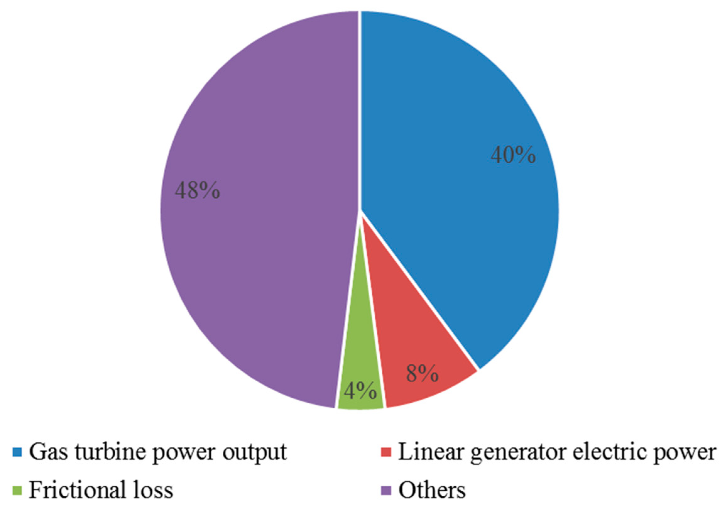
4.3. Energy Distribution

The chemical energy from the burned fuel is transferred to turbine power output, electric power, and system frictional loss, and part of the energy is consumed by heat transfer through the cylinder, gas leakage through the piston rings, exhaust gas, etc. The energy distribution of the burned fuel is illustrated in Figure 5. The energy taken by the heat transfer through the cylinder, gas leakage through the piston rings, exhaust, etc. is marked as “Others” in Figure 5. The system frictional loss is low compared with the traditional reciprocating engines (nearly 10% of the indicated power) [32]. It is found that more than half of the chemical energy from the burned fuel is consumed by “Others”, i.e., energy lost as heat to the jacket water and the exhaust gas.

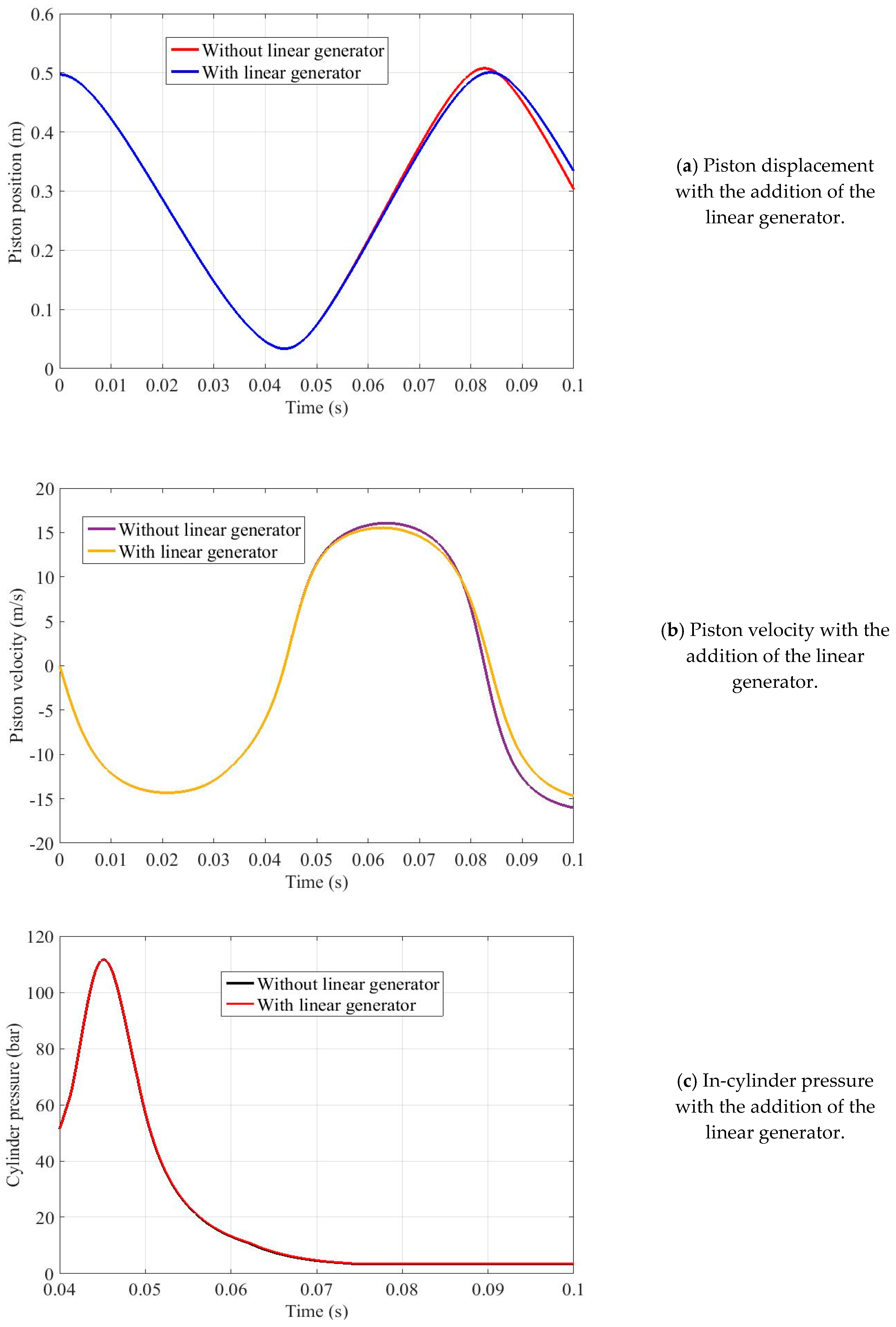
4.4. Piston Dynamics

The comparison of piston position with the addition of the linear generator is illustrated in Figure 6a. The number of the generators adopted was set to 4. When the free-piston engine is connected with a linear generator, the bottom dead centre achieved is lower, and less energy is stored in the bounce chamber. The free-piston engine stroke decreases by 1.3% (from 507.5 mm to 500.7 mm) when a linear generator is connected. The force from the linear generator acts as a resistance force on the piston, i.e., it helps slow down the piston during the expansion process.
The data shown in Figure 6b demonstrates the piston velocity with/without the linear generator. If a linear generator is connected, the peak piston velocity is reduced by 3.3% (0.53 mm). In addition, the engine operation frequency is higher without the addition of the linear generator. When a linear generator is connected, the free-piston engine operation frequency is 11.9 Hz, and it improves to 12.0 Hz without the connection of a linear generator.

4.5. Engine Thermodynamics

The cylinder pressure with the addition of the linear generator is shown in Figure 6c. The power piston is assumed to be controlled to the same top dead centre position. When the same ignition timing and injected fuel amount are employed, the achieved peak cylinder pressure is the same. Very minimal difference is observed as the influence of the resistance from the linear generator is not significant relative to the combustion force.
The comparison of the cylinder pressure force with the resistance force from the linear electric generator is shown in Figure 6d. The peak cylinder pressure achieved is approximately 110 bar, so the peak cylinder pressure force can reach up to 1000 kN. While the maximum resistance force from the linear generator is nearly 20 kN, it is much lower than the peak cylinder force. As a result, with the addition of the linear electric generator (of comparable size with the one selected in this section), the influence on the piston net force is not significant. As a result, it appears that the piston dynamics and system thermodynamic performance are not affected significantly with the addition of the generator.
The data shown in Figure 7a are the gas pressure in the bounce chamber. It was found that without the linear generator, the peak pressure achieved in the bounce chamber is approximately 5 bars higher than that with the linear generator. Without the linear generator, the mechanical energy of the piston during the expansion process is converted to the compression energy of the gas in the bounce chamber, thus a higher peak pressure is observed. It is to be noted that when the free-piston engine is connected to a linear generator, part of the mechanical energy of the piston will be converted to electricity by the generator.
The gas pressure in the compressor is shown in Figure 7b. The thermodynamic process in the compressor is assumed to be an isentropic process. The inlet pressure for the compressor is assumed to be equal with the ambient pressure. The valve is assumed to be open immediately, and the pressure in the compressor is assumed to be equal with the ambient pressure instantly after the inlet valve of the compressor opens. The changing trend of the compressor pressure is the same when a linear generator is connected.

5. Parametric Analysis

5.1. Different Engine Load

The engine’s power output can be adjusted by varying the injected fuel mass. The effect of varied engine load on the engine performance was simulated. The combustion process was assumed to be perfect. The data in Figure 8a shows the cylinder pressure vs piston displacement of the TCFPEG system at varying engine load from 60% to 100% in 10% intervals. The number of linear generators connected with the free-piston was set to 4 and the other input parameters remained the same. The power piston was at its bottom centre at the beginning of the simulation and it was assumed to be controlled to arrive at the same top dead centre. The peak cylinder pressure varied in positive correlation with the engine load, with higher engine load corresponding to higher cylinder pressure. This is due to burning of more fuel during the combustion process.
The influence of engine load on the piston displacement is shown in Figure 8b. With a higher engine load, the piston bottom dead centre and the engine’s operating frequency are higher. When the engine load changes from 60% to 100%, the piston bottom dead centre increases by 3.4% (from 498.1 mm to 515.0 mm), and the engine operation frequency increases by 6.5% (from 11.8 Hz to 12.6 Hz). As the piston is not limited by a mechanical system, its movement is affected by the net force acting on it. With a higher engine load, corresponding to more energy released during the combustion process, the pressure force acting on the piston is higher, and the piston will move faster. As a result, more mechanical energy at the piston is generated, and more compression energy will effectively be stored in the bounce chamber to stop the piston.
The system power output with different free-piston engine loads is presented in Figure 8c. The total amount of turbine power output and electric power is marked as “useful power” in Figure 8c. At higher engine loads, the engine indicated power, turbine output power, and electric power output from the linear generator increases. The changing rate of the engine indicated power is higher. When the engine load is set to 100%, the useful power output is approximately 1 MW. This indicates that with a TCFPEG system of comparable size to the one used in this research, the system output power is able to reach the 1 MW target by varying the system operation conditions.
The system efficiency with different free-piston engine loads is shown in Figure 8d. It was found that the system efficiency is higher with a partial engine load. This is because the linear generator electric power is not increased significantly with the engine load. When the engine load is set to 60% of its full load, the system efficiency achieved is approximately 33.1%, which is 1.4% higher than that with a full engine load. Meanwhile, the inlet temperature of the gas turbine is lower when the engine is operated at partial load, which is better practice for maintaining the integrity of gas turbine components.

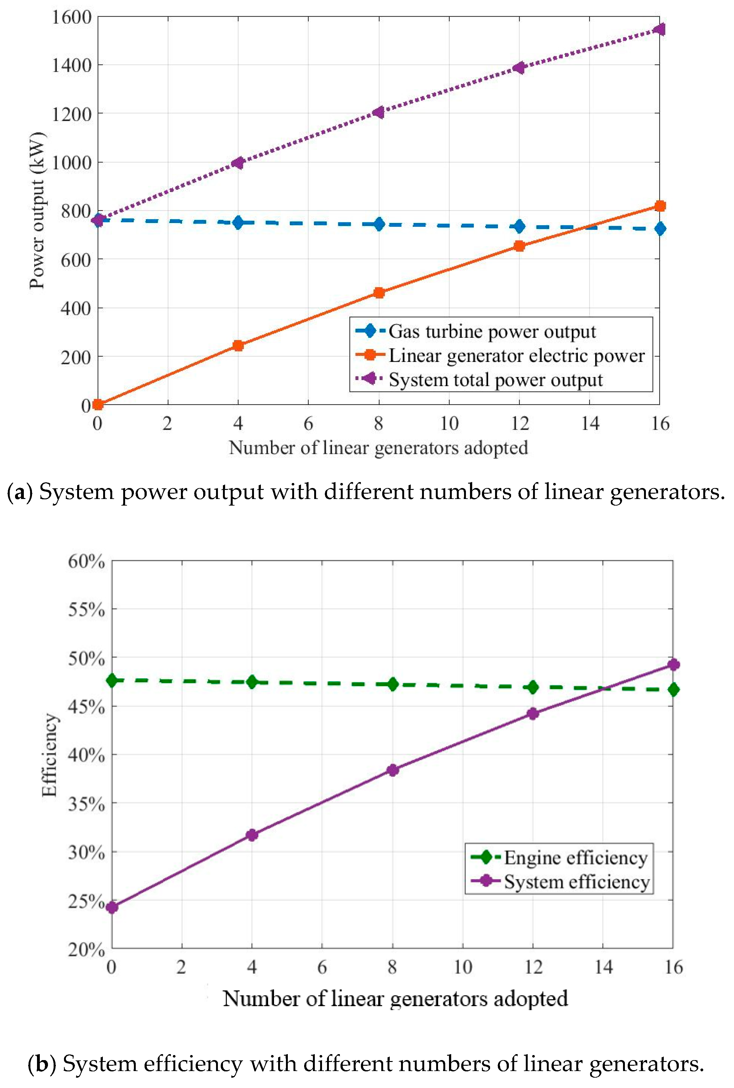
5.2. Effect of the Number of Linear Generators Connected with the Free-Piston Engine

When a linear electric generator is coupled with a free-piston engine, it was found that the power output can be further increased. The number of linear generators connected with the free-piston engine can be varied. The other input parameters remained unchanged during the simulation. The fuelling rate is 5670 mg/cycle (engine load nearly 100%). The linear generator extracts energy during the power expansion stroke, and the force from the linear electric generator acts as a resistance force on the piston. During the compression stroke, the linear electric machine can be used as an active controller to ensure a stable combustion process. The inlet mass flow rate of the gas turbine is determined from the fuel injection amount, air fuel ratio used in the simulation, and the engine operation frequency, which was in the range of 2.5–3.0 kg/s during the simulation presented in this section.
Figure 9a,b shows the system power output and efficiency, respectively, with the number of linear generators connected with the free-piston engine changing from 0 to 16 with an interval of 4. When the number of linear generators is higher than 16, the outward dead point of the piston and the peak pressure in the bounce chamber are significantly reduced. Consequentially, the bouncing force is not enough to drive the piston to the desired compression ratio, which may lead to engine misfire.
Based on the simulation results, the turbine energy output is slightly reduced because the overall operating pressure and mass flow rate drops. More energy extracted by the generator would cause the reductions of engine frequency as a larger generator applies higher force against the piston. Without the linear electric generator, the power output from the free-piston engine coupled with gas turbine (similar configuration with the SIGMA-GS34 system) is nearly 800 kW, with a system efficiency of approximately 25%. When coupled with a linear electric generator, the system power output increases and the system efficiency can be improved to nearly 50%. More power is obtained with more linear generators connected with the free-piston engine, while higher generator output may not be realistic, considering the physical limitation of the linear generator.

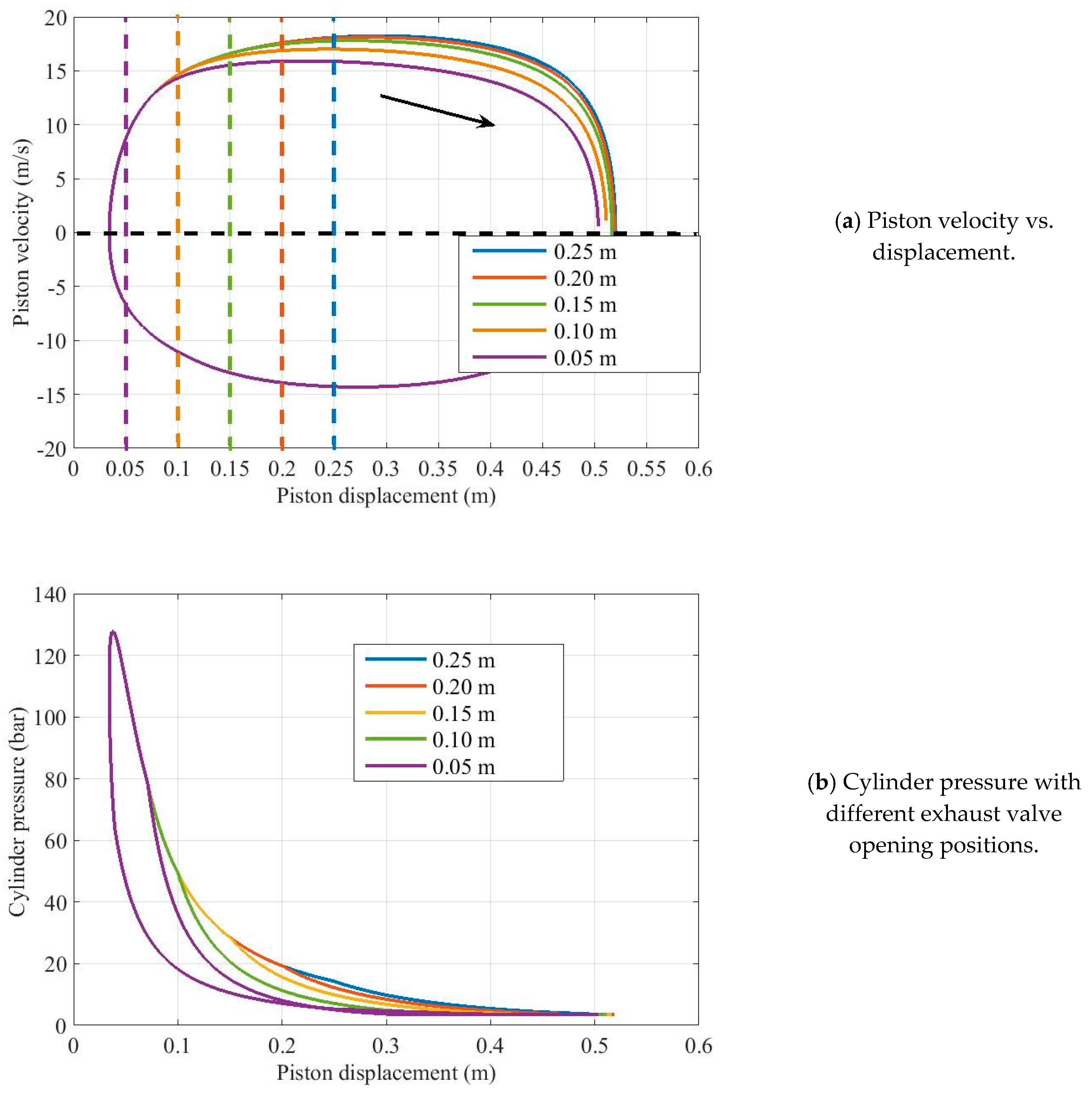
5.3. Different Valve Timings

This analysis seeks to fix the pressure ratio (PR) across the gas turbine to its maximum component efficiency by controlling the FPEG operating parameters to maintain this pressure ratio. The impact of the other free-piston engine control parameters was explored in order to maximise the overall system efficiency. This study attempts to achieve this by increasing the overall system PR, above what would conventionally be achievable with a standalone gas turbine, by extracting any excess energy in the FPEG unit, and thus still maintaining the optimal PR across the gas turbine. The analysis involved varying the FPE compression ratio whilst optimising the exhaust valve opening timing and fuel flowrate to maintain optimal turbine PR. The overall system efficiency was monitored.
The exhaust valve opening timing is defined as the distance from the centreline to the valve opening position. It determines the position where the high-pressure combustion products inside the cylinder will be released into the exhaust manifold. Therefore, the later the valve opens, the further the piston will travel during the outward stroke of the expansion process. If the exhaust valve opening position is further from the centreline, the piston travels further outward, and the engine operation frequency increases as the higher pressure makes the piston move faster. This can be seen clearly in the piston velocity–displacement profile in Figure 10a. The dashed lines in Figure 10a refer to corresponding exhaust valve opening positions distinguished by different colours.
It is obvious that the later the exhaust opens, the larger the outward centre, leading to higher bounce chamber pressure and an effective compression ratio. The power piston was at its bottom dead centre at the beginning of the simulation, and it was assumed to be controlled to arrive at the same top dead centre. The effect of change in exhaust valve opening position on the in-cylinder pressure and piston displacement spectra is shown in Figure 10b. The other parameters like injection timing, injected fuel amount, intake valve opening/closing timing, exhaust valve closing timing etc. remained unchanged throughout the simulation. The engine load was set to 65% of its full load condition.
From the simulation results above, by adopting different exhaust valve opening positions, the piston velocity and cylinder pressure profiles are affected. The piston velocity is one of the key parameters influencing the electric power output, and the cylinder pressure affects the inlet temperature and pressure ratio of the gas turbine. The system power output is changed with different exhaust valve opening positions, which is shown in Figure 11a. It was found that the later the exhaust valve opens, the higher electric power can be achieved, while the turbine output power increases significantly with earlier exhaust valve opening timing. The total amount of the turbine output power and the electric power, or the system whole power output, increases with earlier exhaust valve opening timing. The system whole power output can, in principle, reach 900 kW when the exhaust valve opens at 0.05 m from the centre line.
The whole system efficiency and the free-piston engine efficiency with different valve opening positions is shown in Figure 11b. With later exhaust valve opening timing, a higher free-piston engine efficiency will be achieved. It should be noted that in the simulation, the influence of the exhaust valve opening timing on engine scavenging performance is not considered, thus, the free-piston engine efficiency is much higher than that in the literature. In practical, very late exhaust valve opening timing is not suggested, as it might reduce the scavenging efficiency, thus reducing the corresponding engine efficiency, while the whole system efficiency is higher with earlier exhaust valve opening timing. Opening the exhaust valve earlier leads to more of the energy generated by the exhaust gas via the turbine, while the influence on the linear generator electric power output is minimal compared with that on the gas turbine output power (as shown in Figure 11a). Thus, the whole system efficiency is improved with an earlier opening timing of the exhaust valve. The whole system efficiency can reach up to 48% when the exhaust valve opens at 0.05 m from the centre line. When the exhaust valve opening position is set to 0.05 m from the centre line, the distribution of the burnt fuel is shown in Figure 12.

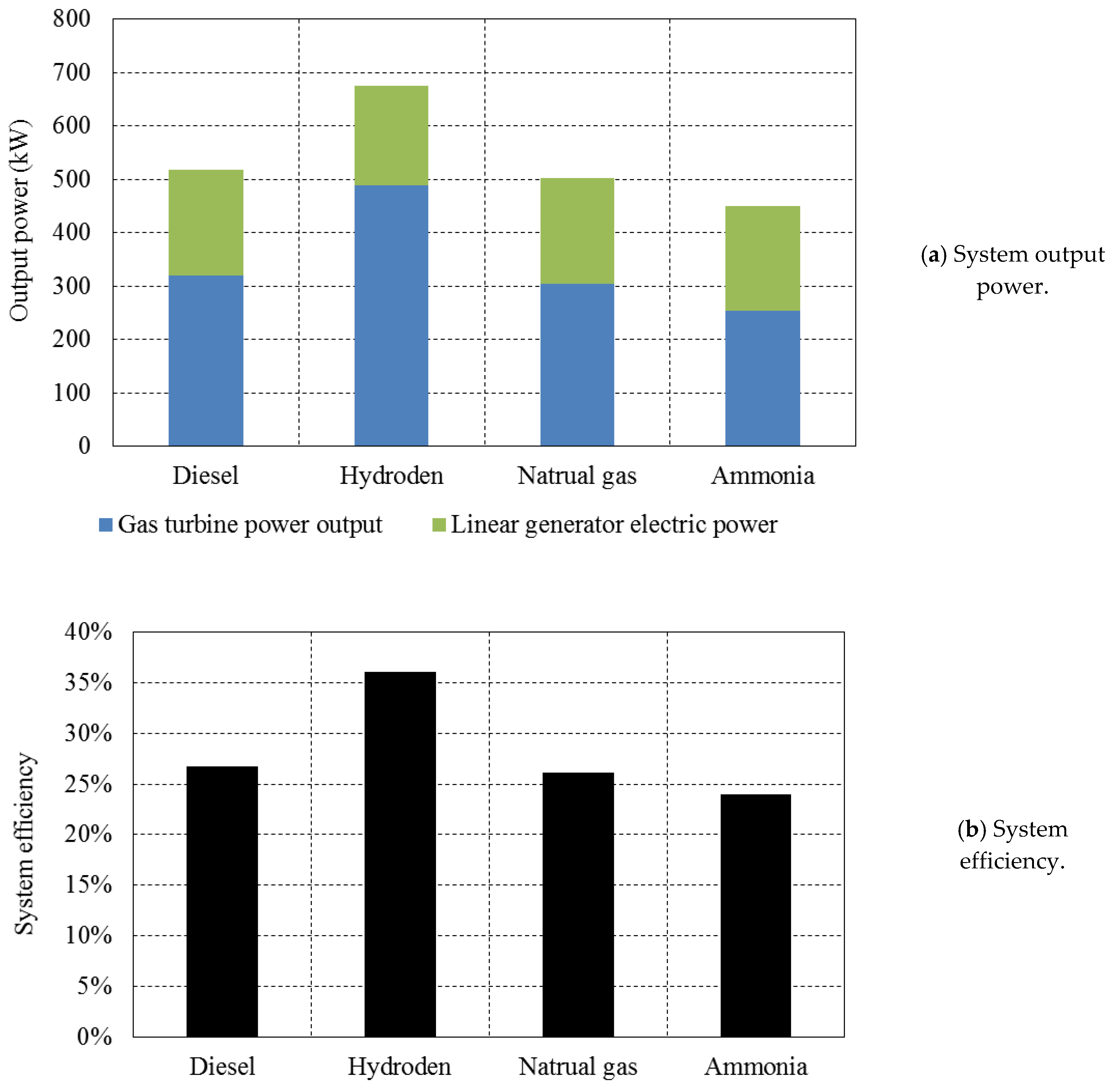
5.4. Potential for Fuel Flexibility for a TCFPEG

This analysis explores how the proposed TCFPEG system might operate successfully when using different fuels. Similarly, the pressure ratio across the gas turbine is set to the component optimal operating performance, and the FPEG will be used to extract useful work and control the temperature and pressure to the inlet of the gas turbine.
The following representative fuels were used: (1) natural gas, (2) diesel, (3) hydrogen, (4) ammonia. During the simulation, the engine was operated at partial load, and the released heat per cycle as fixed with different fuels. The excess air ratio was set to 2.0, and the exhaust valve opening position was set to 0.25 m from the centre line. The system output power with different fuel types is shown in Figure 13a, and the corresponding system efficiency is shown in Figure 13b. It was found that the system is able to be operated with different fuels as the piston is not limited by a mechanical system, thus the engine compression ratio is variable, making it flexible to meet fuel specific limitations.
The output power and system efficiency are highest when hydrogen is used as the fuel. The difference in electric power output is not significant with different fuels, while turbine output is much higher when using hydrogen as fuel input. The combustion properties of hydrogen such as high calorific value, flame speed, and shorter quenching distance produces effective combustion with a high amount of energy compared to other fuels used in the present study. These unique combustion characteristics of hydrogen fuel makes the TCFPEG system to achieve maximum efficiency and power output. The corresponding system efficiency can reach up to 36% without further optimisation. When diesel and natural gas are selected as fuel input, the system efficiency is approximately 27% for both. The system efficiency achieved was lowest when using ammonia as the fuel, which is around 24%.

6. Conclusions

In this study, the performance of the designed TCFPEG system was predicted using a validated numerical model. The influence of engine load and valve timing on engine performance were analysed. The effect of adaptation of a number of linear generators and different types of fuels on system performance were carried out to find its efficiency and output. The outcomes of the present investigation are summarized below.
  • The analysis confirmed that the peak cylinder pressure varied in positive correlation with the engine load without notable effect on the engine compression ratio.
  • With a higher load, the engine operated at higher frequency, and its indicated power changing rate was developed. The system attained more efficiency, whereas the inlet temperature of the turbine was lowered at partial engine load.
  • It was found that the bottom dead centre (BDC), the peak piston velocity, and the engine operation frequency were all reduced when linear electric generators were connected to the system. Very minimal difference in the in-cylinder pressure and the compressor pressure were observed, while the peak pressure in the bounce chamber was reduced.
  • The system’s total output and efficiency were increased when it operated at 65% of engine’s total load with 4 linear electric generators. Meanwhile, the turbine power output was reduced due to a drop in operating pressure.
  • The system achieved 25% of efficiency when it operated without a linear electric generator. This could be improved to nearly 50% by optimising the engine load and the number of linear generators adopted in the TCFPEG system.
  • It was found that the system gives more power output and efficiency with the use of hydrogen fuel compared to other fuels. With the hydrogen fuel, the system efficiency could reach up to 36%, and it was around 24% for ammonia as a fuel.

Author Contributions

B.J.: Planned and carried out the simulations/modelling and wrote the original manuscript with input from all authors; A.S.: Correspondence, supervision and provided critical feedback in shaping the research, analysis and writing the manuscript; R.M.: Critical feedback, supervision and analysis; K.V.S.: Analysed the data and wrote the manuscript in consultation with all authors; S.R.: Analysed the data and wrote the manuscript in consultation with all authors; A.P.R.: In-charge of overall direction and planning.

Funding

This research was funded by EPSRC (Engineering and Physical Sciences Research Council) grant number EP/K503885/1 and EP/R041970/1, the APC was funded by EPSRC (Engineering and Physical Sciences Research Council).

Conflicts of Interest

The authors declare no conflicts of interest.

Abbreviations:

BDCBottom dead centre
FPEFree-piston engine
FPEGFree-piston engine generator
EGRExhaust gas recirculation
HCCIHomogeneous charge compression ignition
HFPEHydraulic free-piston engine
kWKilowatt
NOxOxides of nitrogen
PPMPulse pause modulation
PRPressure ratio
SIGMA GSSociété Industrielle Générale de Mécanique Appliquée (General Industrial Company of Applied Mechanics) generator system
TCFPEGTurbine-combined free-piston engine generator
TDCTop dead centre

References

  1. Jia, B.; Tian, G.; Feng, H.; Zuo, Z.; Roskilly, A.P. An experimental investigation into the starting process of free-piston engine generator. Appl. Energy 2015, 157, 798–804. [Google Scholar] [CrossRef]
  2. Feng, H.; Guo, C.; Yuan, C.; Guo, Y.; Zuo, Z.; Roskilly, A.P.; Jia, B. Research on combustion process of a free piston diesel linear generator. Appl. Energy 2016, 161, 395–403. [Google Scholar] [CrossRef]
  3. Mikalsen, R.; Roskilly, A.P. A computational study of free-piston diesel engine combustion. Appl. Energy 2009, 86, 1136–1143. [Google Scholar] [CrossRef] [Green Version]
  4. Zhao, Z.; Zhang, F.; Huang, Y.; Zhao, C. Determination of TDC in a hydraulic free-piston engine by a novel approach. Appl. Therm. Eng. 2014, 70, 524–530. [Google Scholar] [CrossRef]
  5. Lim, O.; Hung, N.B.; Oh, S.; Kim, G.; Song, H.; Iida, N. A study of operating parameters on the linear spark ignition engine. Appl. Energy 2015, 160, 746–760. [Google Scholar] [CrossRef]
  6. Li, K.; Zhang, C.; Sun, Z. Precise piston trajectory control for a free piston engine. Control Eng. Pract. 2015, 34, 30–38. [Google Scholar] [CrossRef]
  7. Jia, B.; Smallbone, A.; Mikalsen, R.; Feng, H.; Zuo, Z.; Roskilly, A.P. Disturbance analysis of a free-piston engine generator using a validated fast-response numerical model. Appl. Energy 2017, 185, 440–451. [Google Scholar] [CrossRef] [Green Version]
  8. Lee, C.-P. Turbine-Compound Free-Piston Linear Alternator Engine. Ph.D. Thesis, University of Michigan, Ann Arbor, MI, USA, 2014. [Google Scholar]
  9. Underwood, A.F. The GMR 4-4 “HYPREX” Engine A Concept of the Free-Piston Engine for Automotive Use; SAE Technical Paper; SAE International: Warrendale, PA, USA, 1957. [Google Scholar]
  10. Tikkanen, S.; Lammila, M.; Herranen, M.; Vilenius, M. First Cycles of the Dual Hydraulic Free Piston Engine; SAE Technical Paper; SAE International: Warrendale, PA, USA, 2000. [Google Scholar]
  11. Zhang, S.; Zhao, C.; Zhao, Z. Stability analysis of hydraulic free piston engine. Appl. Energy 2015, 157, 805–813. [Google Scholar] [CrossRef]
  12. Zhao, Z.; Zhang, F.; Huang, Y.; Zhao, C.; Guo, F. An experimental study of the hydraulic free piston engine. Appl. Energy 2012, 99, 226–233. [Google Scholar] [CrossRef]
  13. Woo, Y.; Lee, Y.J. Free piston engine generator: Technology review and an experimental evaluation with hydrogen fuel. Int. J. Automot. Technol. 2014, 15, 229–235. [Google Scholar] [CrossRef]
  14. Jia, B.; Zuo, Z.; Feng, H.; Tian, G.; Smallbone, A.; Roskilly, A.P. Effect of closed-loop controlled resonance based mechanism to start free piston engine generator: Simulation and test results. Appl. Energy 2016, 164, 532–539. [Google Scholar] [CrossRef]
  15. Miao, Y.; Zuo, Z.; Feng, H.; Guo, C.; Song, Y.; Jia, B.; Guo, Y. Research on the Combustion Characteristics of a Free-Piston Gasoline Engine Linear Generator during the Stable Generating Process. Energies 2016, 9, 655. [Google Scholar] [CrossRef]
  16. Max, E. FPEC, Free piston energy converter. In Proceedings of the 21st Electric Vehicle Symposium & Exhibition, EVS, Monte Carlo, Monaco, 2–6 April 2005. [Google Scholar]
  17. Kock, F.; Haag, J.; Friedrich, H.E. The Free Piston Linear Generator-Development of an Innovative, Compact, Highly Efficient Range-Extender Module; SAE Technical Paper; SAE International: Warrendale, PA, USA, 2013. [Google Scholar]
  18. Haag, J.; Ferrari, C.; Starcke, J.H.; Stöhr, M.; Riedel, U. Numerical and Experimental Investigation of In-Cylinder Flow in A Loop-Scavenged Two-Stroke Free Piston Engine; SAE Technical Paper; SAE International: Warrendale, PA, USA, 2012. [Google Scholar]
  19. Haag, J.; Kock, F.; Chiodi, M.; Mack, O.; Bargende, M.; Naumann, C.; Slavinskaya, N.; Heron, A.; Riedel, U.; Ferrari, C. Development Approach for the Investigation of Homogeneous Charge Compression Ignition in a Free-Piston Engine; SAE Technical Paper; SAE International: Warrendale, PA, USA, 2013. [Google Scholar]
  20. Kosaka, H.; Akita, T.; Moriya, K.; Goto, S.; Hotta, Y.; Umeno, T.; Nakakita, K. Development of Free Piston Engine Linear Generator System Part 1-Investigation of Fundamental Characteristics; SAE Technical Paper 0148-7191; SAE International: Warrendale, PA, USA, 2014. [Google Scholar]
  21. Goto, S.; Moriya, K.; Kosaka, H.; Akita, T.; Hotta, Y.; Umeno, T.; Nakakita, K. Development of Free Piston Engine Linear Generator System Part 2-Investigation of Control System for Generator; SAE Technical Paper 0148-7191; SAE International: Warrendale, PA, USA, 2014. [Google Scholar]
  22. Jia, B.; Zuo, Z.; Feng, H.; Tian, G.; Roskilly, A.P. Development Approach of A Spark-Ignited Free-Piston Engine Generator; SAE Technical Paper 0148-7191; SAE International: Warrendale, PA, USA, 2014. [Google Scholar]
  23. Jia, B.; Zuo, Z.; Feng, H.; Tian, G.; Roskilly, A.P. Investigation of the starting process of free-piston engine generator by mechanical resonance. Energy Procedia 2014, 61, 572–577. [Google Scholar] [CrossRef]
  24. Li, Y.-X.; Zuo, Z.-X.; Feng, H.-H.; Jia, B.-R. Parameters matching requirements for diesel free piston linear alternator start-up. Adv. Mech. Eng. 2015, 7, 1–8. [Google Scholar] [CrossRef]
  25. Jia, B.; Zuo, Z.; Tian, G.; Feng, H.; Roskilly, A.P. Development and validation of a free-piston engine generator numerical model. Energy Convers. Manag. 2015, 91, 333–341. [Google Scholar] [CrossRef]
  26. Jia, B.; Smallbone, A.; Feng, H.; Tian, G.; Zuo, Z.; Roskilly, A.P. A fast response free-piston engine generator numerical model for control applications. Appl. Energy 2016, 162, 321–329. [Google Scholar] [CrossRef]
  27. Jia, B.; Smallbone, A.; Zuo, Z.; Feng, H.; Roskilly, A.P. Design and simulation of a two-or four-stroke free-piston engine generator for range extender applications. Energy Convers. Manag. 2016, 111, 289–298. [Google Scholar] [CrossRef]
  28. Mikalsen, R.; Roskilly, A.P. The design and simulation of a two-stroke free-piston compression ignition engine for electrical power generation. Appl. Therm. Eng. 2008, 28, 589–600. [Google Scholar] [CrossRef] [Green Version]
  29. Barnes, A.F. Simulation of Full and Part-Load Performance of A Free-Piston Gas Generator by Electronic Analog Methods. Master’s Thesis, US Naval Postgraduate School, Monterey, CA, USA, 1960. [Google Scholar]
  30. Ngwaka, U.; Jia, B.; Lawrence, C.; Wu, D.; Smallbone, A.; Roskilly, A.P. The characteristics of a Linear Joule Engine Generator operating on a dry friction principle. Appl. Energy 2019, 237, 49–59. [Google Scholar] [CrossRef]
  31. Hanipah, M.R. Development of A Spark Ignition Free-Piston Engine Generator. Ph.D. Thesis, Newcastle University, Newcastle, UK, 2015. [Google Scholar]
  32. Heywood, J.B. Internal Combustion Engine Fundamentals; Mcgraw-Hill: New York, NY, USA, 1988; Volume 930. [Google Scholar]
Figure 1. Turbine-combined free-piston engine generator (TCFPEG) configuration.
Energies 12 02657 g001
Figure 2. TCFPEG operation.
Energies 12 02657 g002aEnergies 12 02657 g002b
Figure 3. Comparison of in-cylinder pressures (test data source [29]).
Energies 12 02657 g003
Figure 4. Linear electric generators and their layouts, (a) Linear electric generator [31], (b) Illustration of system configuration with connection of 4 generators.
Energies 12 02657 g004
Figure 5. Energy distribution of the energy supplied in the fuel without optimisation.
Energies 12 02657 g005
Figure 6. System performance characteristics with and without the linear generator.
Energies 12 02657 g006aEnergies 12 02657 g006b
Figure 7. System dynamic pressures with and without a linear generator.
Energies 12 02657 g007
Figure 8. Results supporting the parametric analysis.
Energies 12 02657 g008aEnergies 12 02657 g008b
Figure 9. System sensitivity to the number of linear generators.
Energies 12 02657 g009
Figure 10. Sensitivity to different exhaust valve opening positions.
Energies 12 02657 g010
Figure 11. Influence of different exhaust valve opening times on performance.
Energies 12 02657 g011aEnergies 12 02657 g011b
Figure 12. Fuel energy distribution when exhaust valve opens at 0.05 m from the centre line.
Energies 12 02657 g012
Figure 13. Influence of different types of fuel.
Energies 12 02657 g013
Table 1. Design parameters of the TCFPEG.
Parameter [Unit]Value
Combustion engineCylinder bore [m]0.340
Engine stroke [m]0.965
Piston mass [kg]500
Bounce chamberBore [m]0.895
Stroke (per piston) [m]0.445
Compressor chamberEffective bore [m]0.823
Stroke (per piston) [m]0.445
Table 2. Comparison of performance for the addition of linear generator.
Linear GeneratorWithWithout
Free-piston engine indicated efficiency (%)45.946.30
Bottom dead centre (m)0.50070.05075
Top dead centre (m)0.033740.03374
Engine indicated power (kW)891.9908.6
Gas turbine generator output (kW)422.7441.9
Linear generator electric power output (kW)197.20
Overall system efficiency (%)3222.50

