Article

Energy-Effective Cooperative and Reliable Delivery Routing Protocols for Underwater Wireless Sensor Networks

1
Department of Electronics, Quaid-i-Azam University Islamabad, Islamabad 45320, Pakistan
2
Department of Electronics, University of Peshawar, Peshawar KPK 25120, Pakistan
3
Tecnologico de Monterrey, Escuela de Ingenieria y Ciencias, Monterrey 64849, Mexico
4
Department of Computer System and Technology, Faculty of Computer Science and Information Technology, University of Malaya, Kualalumpur 50603, Malaysia
5
Department of Computer Science, COMSATS University, Islamabad 44500, Pakistan
6
Department of Information Technology, The University of Haripur, Haripur 22620, Pakistan
*
Authors to whom correspondence should be addressed.
Energies 2019, 12(13), 2630; https://doi.org/10.3390/en12132630
Submission received: 28 April 2019 / Revised: 27 June 2019 / Accepted: 1 July 2019 / Published: 9 July 2019

Abstract

:
Underwater deployed sensors nodes are energy-constrained. Therefore, energy efficiency becomes crucial in underwater wireless sensor networks (U-WSNs). The adverse channel corrupts the packets and challenges their reliability. To handle these challenges, two routing schemes are introduced in this paper. They are effective energy and reliable delivery (EERD) and cooperative effective energy and reliable delivery (CoEERD). In EERD, the packets follow single-path routing and the best forwarder node is selected using a weight function such that packets are transferred via the reliable paths with low energy usage. Packet transfer via a single route in EERD has, however, compromised reliability as the undersea links bear harshness and unpredictability. Therefore, the CoEERD scheme adds cooperative routing to EERD, in which a relay node is introduced between a source–destination pair. The destination requests the relay when the packets it gets from the source are corrupted beyond a threshold value. Selection of weight function is unique and considers many factors to ensure low energy usage with reliability while considering nodes for data transfer. This also helps in selecting a single relay node rather than many relays in the conventional cooperative routing model. Based on simulation results, the EERD and CoEERD protocols have improved performance in energy usage, reliable packet transfer and delay.

1. Introduction

Ocean covers more than 70% of the surface area of Earth. There are various applications related to the ocean environment such as scientific exploration and surveillance of the sea [1]. Underwater sensor networks (U-WSNs) have emerged to study undersea circumstances for these and other applications [2,3].
In U-WSNs, there are many sensor nodes available in the network [4]. The nodes have the capability to sense the information and forward towards the upper surface sink node. The information packets of the sink node are processed further for various applications. The received data packet accuracy is mostly dependent on the errorless communication. The ocean has time-varying link properties and severe noise [5], which make the underwater networks more challenging to have an optimal data transmission. Water has absorbing properties for radio waves so U-WSNs use acoustic signals [6], which provide optimal performance [7,8].
Reducing the energy consumption is one of the major concerns in U-WSNs [9]. The replacement of the node batteries in the sea is quite a difficult job. However, for better network lifetime and error-free communication, researchers are focused on introducing innovative routing schemes for U-WSNs as one of the potent remedies. Furthermore, to design the routing protocols for U-WSNs, it is necessary to identify the challenges of this channel: low battery power, time-varying channel, and low allowable bandwidth [10,11].
Another important issue faced by underwater communication is network reliability. Cooperative routing (CR) is one of the optimal solutions to ensure a reliable network by traveling the information over multi-paths [12]. Cooperative routing also decreases the contrary channel effects and holds a reliable information transmission by considering the source node (SRN) towards the sink. CR uses two techniques for packet advancement: in one technique the data is first amplified and then forwarded (AF) and in the second technique the data is first decoded and forwarded (DF). CR makes the SRN able to advance the packet over multi-cast mode, where the SRN transmits the information towards the multi-nodes at the same time, instead of sending to a single node.
The existing optimized depth base routing (ODBR) is basically a single-path routing scheme, which considers only local depth information for the selection of data advancer node [13]. This information is not adequate to specify the position of the nodes. In addition, the situation becomes worse when two nodes at the same depth forward the redundant information towards the sink node. The lowest depth nodes in ODBR become dead quickly due to continuous transmission of packets towards the sink node. Likewise, the cooperative depth base routing (CoDBR) is a multi-path routing scheme [14]. Like ODBR scheme, the CoDBR scheme also considers the lowest depth criteria for the selection of best forwarder nodes. Moreover, the CoDBR scheme selects two relay nodes (RLNs) with the destination (DSN), which increases the contribution of these nodes during the routing but consumes high energy.
To solve the aforementioned issues, this paper introduces two routing schemes: EERD and CoEERD. The EERD scheme is a non-cooperative scheme, which reduces the net energy cost by traveling the information over a single path. In addition, during the selection of the best forwarder node, the robust weight function parameters make it more efficient to consume minimum energy. In EERD, the SRN transmits a control packet (CP) to collect the nodes information in terms of node IDs, residual energy, distance, and bit error rate (BER). The node with maximum residual energy, lowest BER, and lowest distance is considered to be DSN, which is the highest priority node for information packet forwarding in the network.
The second proposed scheme, CoEERD, also defines the same criteria for the selection of DSN. In this scheme, the DSN is selected with the same criterion as in EERD. The RLN is also selected by the SRN which holds the second highest weight function value. The SRN broadcasts the information packets toward the DSN and RLN, the former checks the received packet BER. If the BER exceeds the calculated threshold value, then the DSN sends out a request towards the RLN for sending the same data packet.The RLN amplifies the packet and sends it back towards the DSN, the RLN also sends an acknowledgement (ACK) to the DSN, which combines the two copies of packets through the maximal ratio combining (MRC) mechanism and forwards optimal information directly towards the sink node. However, If the sink node does not lie inside the range, then the DSN selects another DSN and RLN to forward the information. This process is continued unless the information packets reach the sink.

2. Contributions

The contributions of this article are summarized as follows:
  • To minimize the network energy consumption, EERD scheme is designed for U-WSNs, in which the choice of nodes for information forwarding is achieved using certain weight function parameters (highest residual energy, lowest BER, and shortest distance). The scheme chooses a node among the neighbor nodes as a DSN, which has the highest function value. The selection parameter of highest residual energy helps to choose the robust node as a DSN, which prolongs the network lifetime. The shortest distance decreases the path length, which also decreases energy consumption. The scheme reduces the adverse channel impairments, by checking the BER and selecting the best link for further packet forwarding. Due to single-path routing and robust function attribution in the scheme, it decreases the energy consumption, maximizes the network life, and minimizes delay.
  • Single-path routing in EERD decreases the network reliability. To improve the reliability, the CoEERD scheme is introduced, which uses the cooperation of a single RLN with the DSN. The best forwarder nodes (RLN and DSN) are selected by considering the above discussed function parameters. The SRN advances the information packet towards the RLN and DSN using broadcast nature. The DSN checks the BER, if it is above the threshold, it forwards a request (REQ) to the RLN for sending the same packet. The RLN retransmits the packet along with the ACK to DSN. For diversity, the MRC technique is used, which merges packets and advances them further to the final DSN.
  • For quick packet delivery, the shortest Euclidian distance is used as a selection parameter for the best forwarder nodes. The calculation of the shortest distance between the source, DSN, and RLN reduces the path length. The latency during the packet advancement decreases and the ratio of packet delivery increases in both the schemes.
  • Energy consumption is low in the EERD scheme. The inclusion of cooperation to EERD to make the CoEERD scheme uses one more node as a relay node. This increases energy usage of CoEERD. However, it has still lower energy consumption than some other existing schemes involving cooperation.

3. Literature Review

The authors proposed a new energy efficient and delay sensitive scheme for U-WSNs in [15]. The scheme enhances the performance of [16] by using the fuzzy logic technique (FLT), where the best forwarder nodes are selected by considering the node position and energy information. This technique reduces the interference between the nodes. The consideration of residual energy ratio (RER) and fuzzy logic interference technique in the scheme minimizes the expended energy. The node which has the lowest distance position and highest energy is selected as a destination, which transmits the packets to the desired sink through multi-hop paths. The scheme causes a small delay and reduces the energy consumption. However, it reduces the network reliability with high probability of information packet drop.
Pappas et al. [17] access the IoT wireless network in random manner by facilitating two data collectors. Nodes and aggregators are used in order to transmit data packets in random access fashion. The aggregators use network-level cooperation to transmit data packets in slotted time. Moreover, they provide throughput to gain the scalability of network. By doing so, they obtain possibly finite queuing delay. They also attempt to facilitate data collection for IoT. The use of aggregators makes the system complicated.
In [18], the entire network is split into three equal sub-regions. Division of network is an efficient step towards energy saving and ratio-of-delivered packet (RODP) enhancement. The approach considers the horizontal and vertical movement of the sink which helps to minimize the packet drop. Cooperation technique is applied to the network with the help of which nodes use cooperation to forward the data. This helps to achieve maximum RODP. The RLN amplifies and decodes the information and sends toward the DSN. During the routing at each destination node, the BER is checked. In case of BER lower than the threshold value, it proceeds the packet successfully in the direction of the desired destination. The nodes selection is set up based on the cost function. The selection of destination node is made on the maximum residual energy, lowest depth, and maximum signal-to-noise-ratio (SNR) values. The protocol achieves high RODP and increases battery life.
To minimize the energy use and avoid the void zone occurrence, two new techniques are presented in [19]. In the first technique the mobile sink nodes play the key role to reduce consumption of the nodes’ energy. The second technique combines routing with cooperation with the first one. The cooperative scheme enhances the network reliability by traveling the packets over multi-paths. In second scheme, the RODP increases, packet drop decreases, and the transmission delay maximizes with cost of maximum energy consumption. The first scheme reduces the energy consumption and keeps the nodes alive for long time.
The authors presented a cooperative technique for energy harvesting in [20]. They presented an overview about the energy limitation for the stable throughput between the SRN, RLN, and the DSN. The SRN and RLN have an unlimited energy harvesting and saving capability. They consider the interior and exterior stability range for the given transmission region. Also relay assisted network is provided. The proposed system has identical performance in the case of intermediate traffic regime. The tracking interacting queue is a difficult task; however, this work obtains it by using insight from a simple model. Moreover, the stable throughput region is considered to achieve connectivity of nodes.
The authors proposed a cooperative scheme in [21] for reliability and saving the nodes’ energy. The cooperation is held among the DSN and the RLN. The selection of RLN and DSN bases on the highest residual energy, lowest depth and channel quality. The scheme uses the sink node mobility for balanced energy consumption. The mobile sink nodes secure the information sent by the sensor nodes and forward towards the final destination. The received packets at destination, is checked for BER. If BER exceeds the threshold value, it sends a REQ towards the RLN. The relay sends the desired packet with ACK to the destination. The MRC technique combines the two packets and forwards optimal information towards the final destination. The scheme saves the network energy due to sink mobility, keeps maximum nodes alive and transmits maximum information. However, it consumes high energy and nodes become dead quickly.
In [22], three different techniques are used to enhance the PDR and reduce the energy usage as well as ignore void node occurrence. The first scheme is cooperative-based opportunistic hydrocast that helps to minimize the unnecessary contributed nodes during transmission. However, it selects the longer distance paths, due to which energy usage increases. The second approach is improved version of the scheme, while the third one is a cooperative improved version. These techniques minimize dropping effect of information as a result energy usage reduces at the cost of high delay. The cooperative improved technique enables the network to achieve higher RODP. by using cooperation. The route setup criteria are the same for all techniques, the nodes are selected to proceed the information towards nodes which are close to the sink and have fewer hops.
The authors proposed a scheme to minimize expended energy in [23]. Four movable sinks are considered, which move according to the sender node position. The movements of the sink are considered only for the horizontal axis. Besides, a cooperation scheme is set among the relay and destination nodes. If any sink node is available in the sender range, then packet is sent to the sink. Otherwise, cooperation is performed. The approach saves the energy of the network. However, it blindly selects the channel link for transmission data which affects the RODP.
To minimize the energy consumption, the author proposed a new routing scheme in [13]. In the scheme, the whole network is split into three equal zones. The energy is optimized in such a manner that the upper region nodes consume low energy due to the short transmission range with respect to the sink node. Nodes lie in the mid and bottom region are energized with higher energy. It also considers the lowest depth criteria for the choice of data forwarder nodes. The scheme reduces the energy consumption due to single-path routing and increases the network lifetime. However, due to single-path routing, it reduces the network reliability and throughput.
In [24], the authors describe that data packets can be made robust against the different channel factors. In this approach, a cooperation scheme is applied to sensor nodes to send data. In cooperation mode, more than one node is used to transmit data in the direction of the sink using different channel links. In this approach, two different selection criteria are defined for relay nodes selection. Firstly, the authors consider the residual energy and depth and then the SNR of the link with depth and residual energy are considered. This approach has high packet transfer to surface but has high delay as well.
To maximize the network reliability, the authors present a cooperative scheme in [14]. The desired function parameters (depth and residual energy) are considered for data forwarder nodes. For cooperation, two relay nodes are used with destination, where the relay and destination nodes are selected by considering the lowest depth criteria. The destination and two relay nodes receive the packet that is sent by the source node. The DSN checks BER and sends a negative acknowledgment (NACK) in case of high BER. The relay node responds over the destination request and retransmits the packet towards the destination along with acknowledgment (ACK). The three received packets are merged by using the diversity technique and optimal information is sent towards the sink node. In case the sink is out of the communication range, multi-hoping is used. The proposed scheme ensures maximum information, increase the network reliability, and reduce the information loss. However, due to cooperation, it consumes high energy and nodes die quickly.
The authors proposed a new routing schemes based on cognitive multiple access for wireless networks in [25]. To avoid the conventional cooperation, the schemes used a cognitive multiple access technique. To reduce the resources use, two routing schemes are introduced. The schemes maximize the stable throughput region and decrease the latency. The result shows that the proposed protocols are superior to the conventional cooperation techniques. Both the proposed schemes increase the network throughput with the achievement of network stability and reduce bandwidth usage. However, it consumes high energy and increases the latency. The overview of all the schemes is illustrated in Table 1.

4. Designed Schemes

This section contains the detailed overview of the EERD and CoEERD schemes. The EERD scheme is non-cooperative, which minimizes the energy cost and retains the network alive for long time. The CoEERD scheme is a cooperative scheme, which increases the RODP and holds the network reliability.

4.1. Effective Energy and Reliable Delivery (EERD) Routing

Network Initialization

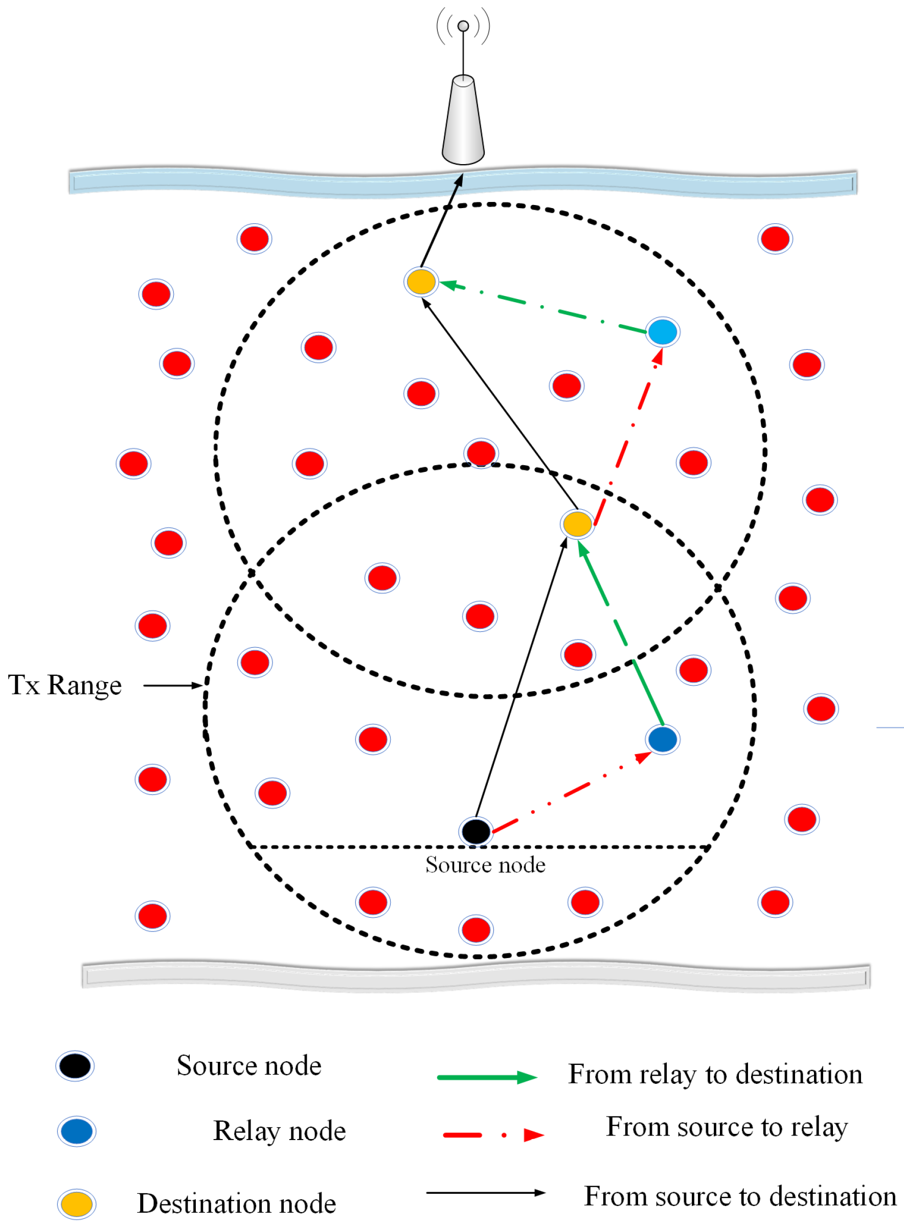
The network dimensions are X × Y × Z , where X, Y, and Z consider the length, depth, and width of the network, respectively. The network contains the source, relay, and sink nodes with random deployment. The position of the sink nodes is specified at the top of the ocean surface as shown in Figure 1, which are further connected to an offshore data center. In the network, each sensor node is responsible for data advancement towards the sink node. The deployed nodes communicate by acoustic links, and sink nodes correspond with the satellite by a radio link. In the network, each sensor node is energized through small battery power. The sink node communicates with sensor nodes by using acoustic links.

4.2. Neighbors Recognition

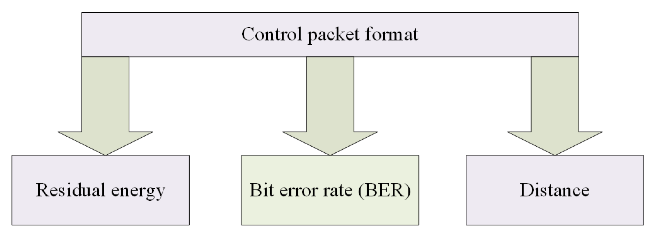
As the network is initialized, all nodes communicate with the sink nodes to know their position coordinates. Then an SRN transmits a CP. All the nodes that exist inside the communication range with respect to the SRN, receive the CP. The CP format is depicted in Figure 2, which consists of the information of maximum residual energy, shortest distance, and lowest BER. The received CP lets the neighbors of SRN to know its residual energy and distance from one of the sink nodes. initially, the BER is computed by detecting the variations of the known bits pattern in the CP Once data routing takes place among the nodes, the BER is computed again for the exchanged data packets.
The upper four sink nodes located at water surface are equipped with GPS. These sink nodes provide help for determining the coordinates of the undersea nodes. By taking one sink node as a reference node in x direction, second sink node in y direction and third in z direction, the distance is calculated by using the time of arrival and the speed of the acoustic waves [26,27]. Moreover, the coordinates of the targeted nodes are estimated by using the relative distance from the surface sinks. Suppose a node has one hop from the sink node specified for x direction coordinates then it means the node has coordinate 1 in the x direction. Likewise, the second and third sink nodes will check the number of hops in y and z order, indicating the corresponding coordinates of the nodes. This process continues and nodes with known coordinates are used as references nodes by other nodes to specify their own coordinates. The process of coordinates’ determination by nodes takes place early at the start when network initialization takes place and before the recognition of neighbors. The CP is also used by nodes to become aware of one another coordinates. After coordinates of the nodes are known, they exchange the information of coordinates. This makes the distance calculation easy among nodes. The CP is broadcasted periodically for the sake of keeping the routing table updated [28]. When a node gets the CP, it inserts its energy and distance information and retransmits it in the direction of the SRN. The SRN collects all the neighbor nodes information and creates a routing table. The unique ID of each sensor node differentiates each node position. The creation of the routing table is essential for the selection of DSN among the neighbors. The process is continued until all the neighbor nodes swap their information with each other. The BER of neighbors is then computed by the node that has received the CP by observing the change in the predefined bit patterns.
For BER calculation, the SRN forwards the CP among the neighbors to check the link quality. By using the Binary Phase-Shift-Keying (BPSK) modulation for Raleigh fading channel, the average BER in data packets can be found as [29],
B E R = 1 S N R 2 + S N R
S N R = P t A ( d , f ) N ( f )
In the above SNR formula, P t is considered to be the transmission power, which is fixed for all the nodes, while A ( d , f ) is the attenuation, d shows the separation of nodes that exchange data, f is the acoustic frequency and N ( f ) shows the noise level. The parameters involved in the computation of the SNR are computed according to their models described in [30,31,32]. These parameters can easily be computed keeping in view the distance and position coordinates of the nodes obtained using the CP and by specifying the acoustic frequency and nature of the acoustic link.
The CP transmission among the neighbor nodes helps to select the favorable link for packet transmission, which has the minimum BER. When the destination node receives the CP in the form of bits, it checks the change in predefined bits pattern, which determines the BER. The bits pattern in the CP for BER calculation is specific and the same for all nodes’ CP and is known to all the nodes.

4.3. Destination Nodes Selection and Information Proceeding

The DSN is purely selected by considering the certain function parameters (highest residual energy, shortest distance, and lowest BER). The final DSN (sink node) receives the packet directly from a neighbor SRN. Otherwise, the SRN sends the packet by considering the multi-hopping. In such a scenario, the SRN first accomplishes the selection of the DSN. The above-mentioned criteria are given below for the selection of DSN, where it is the most probable node for data forwarding.
f = R e s i d u a l e n e r g y B E R × D i s t a n c e
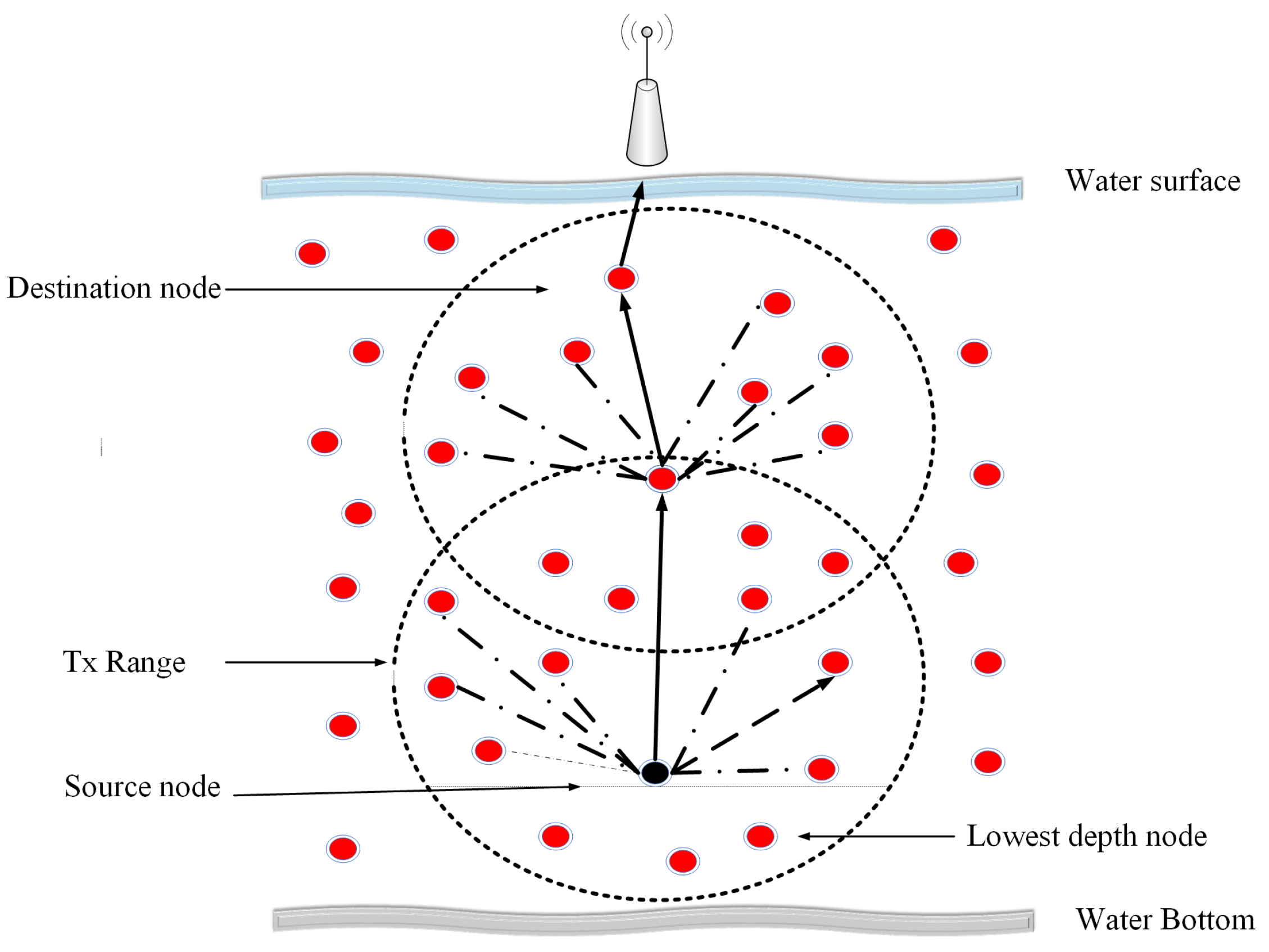
Equation (3) shows that a node closest to the sink node that holds the highest residual energy and lowest BER is specified as the first DSN. The BER should be lower than a threshold value else an optimal relay node is chosen. Upon the DSN selection, the source leads the information packet towards the DSN. The selection criteria for next DSN is same as defined for the first DSN. The process of data forwarding is continued until the packet reaches to the final DSN as shown in Figure 3.
The picture of the data forwarding node with the neighbors is shown in Figure 4.
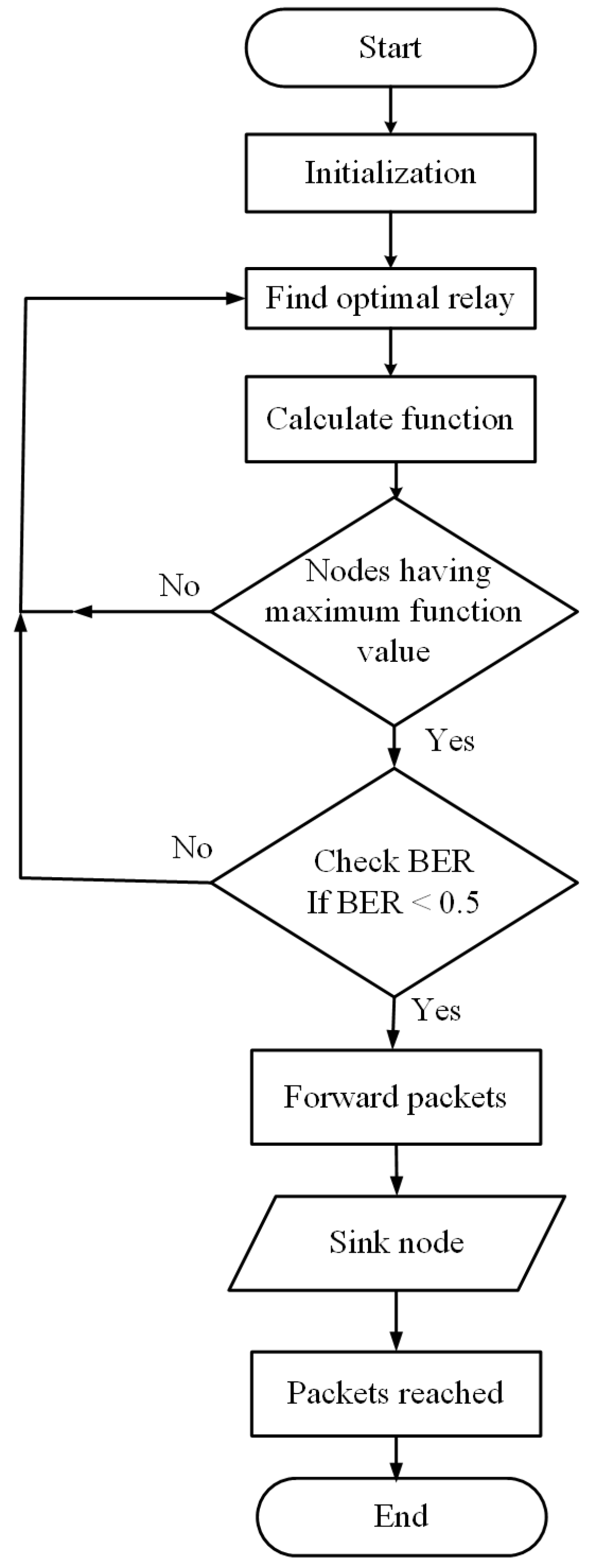
Figure 5 shows that after the network initialization phase, the SRN finds an optimal DSN for the information forwarding. For this purpose, the SRN calculates the function and decides the DSN based on highest function values. The SRN sends the information packet towards the DSN, it checks its BER, in case of low BER it leads the information packet in the direction of the sink node. However, if BER exceeds the threshold value, the DSN discards the packet. This process is continued until the packets get to the sink node.

4.4. Cooperative Effective Energy and Reliable Deliver (CoEERD) Routing

This section involves the detail of CoEERD scheme, which is the cooperative version of the EERD scheme. The cooperation of the single RLN with DSN is used for the network reliability. The basic steps of the CoEERD are given below.

Relay and Destination Node Selection

This section describes the selection of single RLN and DSN. The selection process of the DSN in CoEERD is similar to the EERD scheme. In CoEERD scheme, when an SRN transmits a CP, all the neighbors get it. The best forwarder nodes (RLN and DSN) are chosen based on the function parameters. The node nearest with respect to the sink node and holding the highest residual energy and lowest BER is marked as DSN. RLN and DSN selection is accomplished based on the information of the nodes about their neighbors.

4.5. Data Forwarding and Cooperation

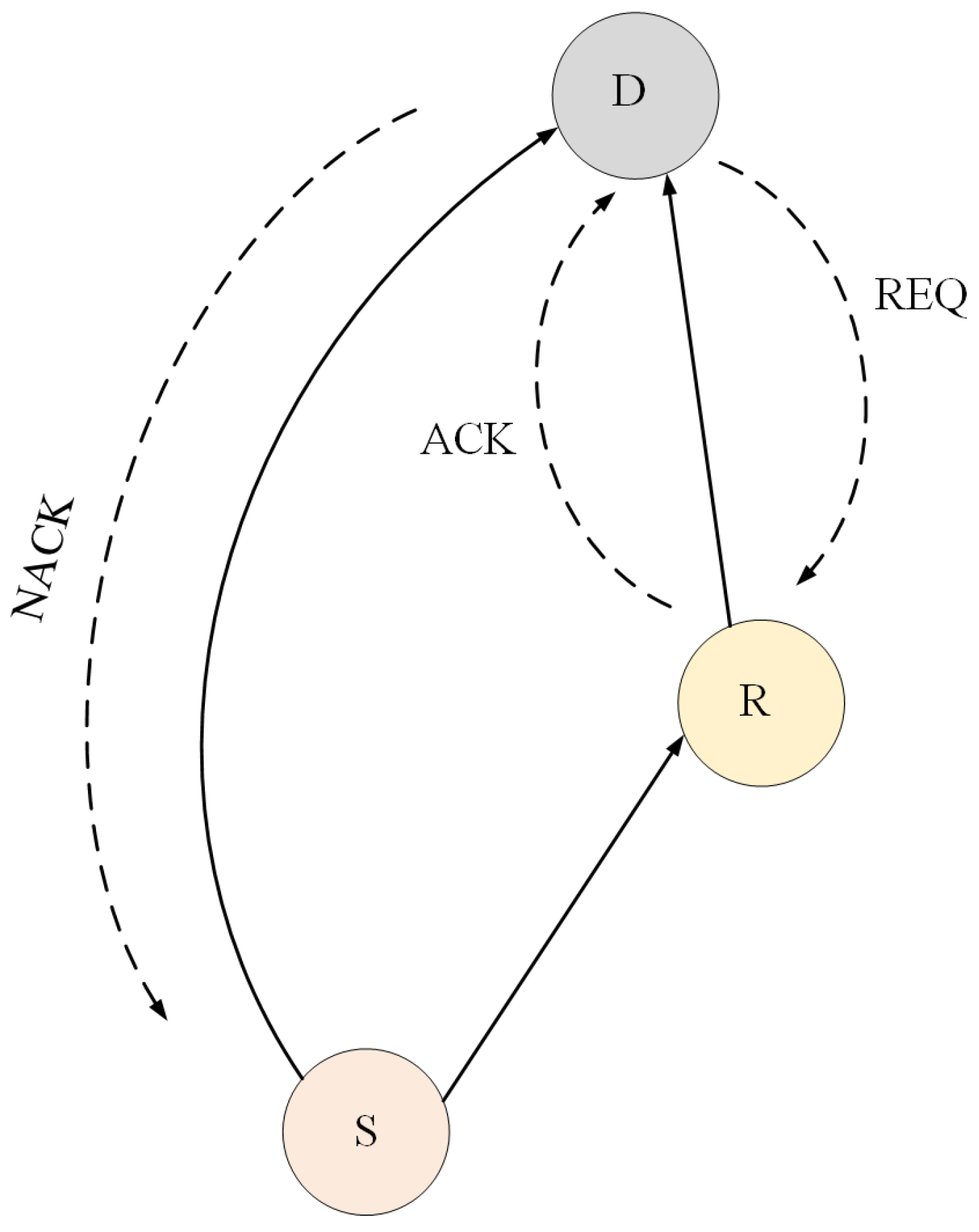
The SRN advances the information packets toward the DSN and the RLN for further forwarding. The DSN checks the received packet BER, if the associated BER value is lower than the measured threshold value, the DSN accepts the information. The DSN checks the final DSN vicinity, if the sink lies inside the communication range then it sends the information directly towards the sink. However, if the received packet BER at DSN exceeds the threshold value, then the DSN sends a REQ towards the RLN to send the same information packet. The RLN waits for the specific interval of time and then amplifies the received packet and sends it back to the DSN with acknowledgment as shown in Figure 6.
The DSN again checks the BER, if the BER again exceeds the threshold value then drops the data packet. Moreover, if the relaying packet BER is less than the threshold, the DSN combines these two received packets through MRC technique [33], and forwards optimal information towards the sink, if the sink is in range. However, in case of the sink does not exists in the communication range of the DSN, then it selects second DSN and second RLN by considering the above criteria. This process is continued until the packet reach to the upper sink nodes by using multi-hoping as shown in Figure 7. The sink node receives the packets and extracts the information and further forwards them to the offshore data center.
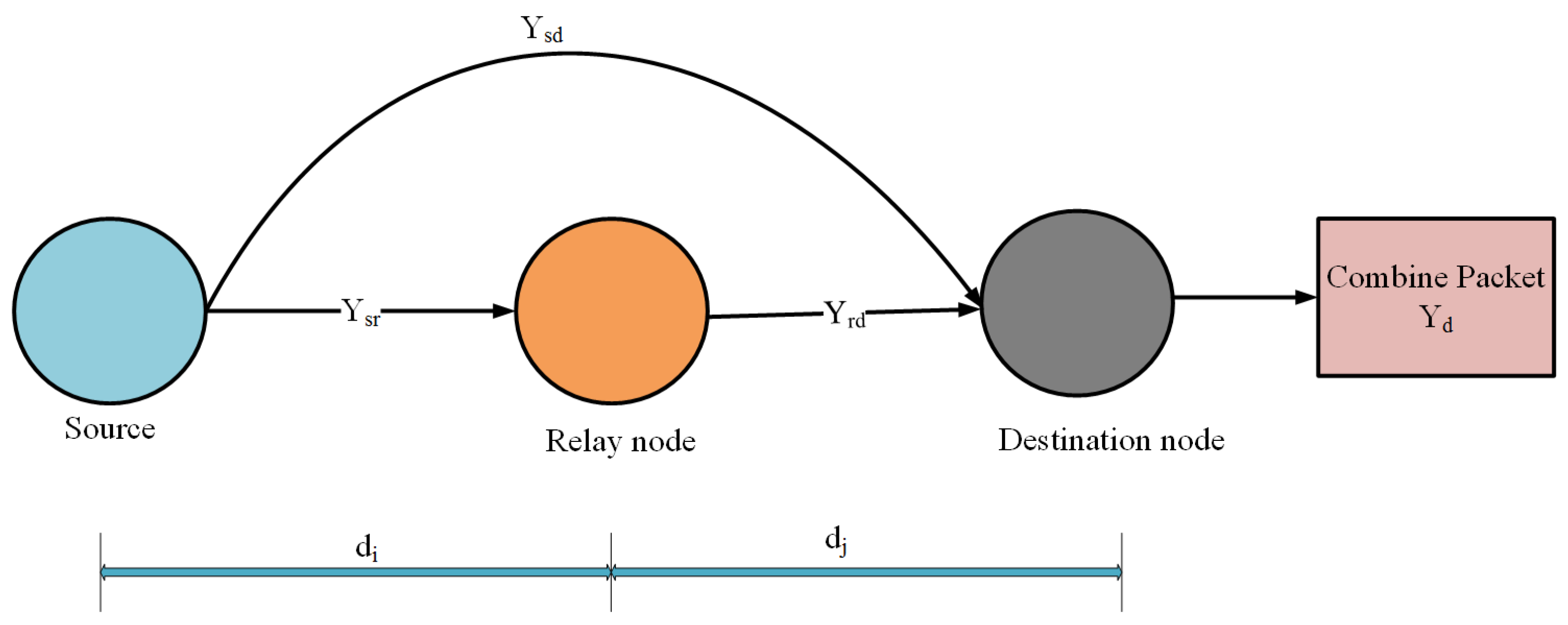
After specifying the DSN and RLN, the SRN broadcasts the information packets and neighbors get them. However, only the DSN and RLN contribute to the forwarding of the information. The packet received at the DSN and transmitted by the SRN is modeled as [34],
Y s d = b G s d + N s d
where Y s d is the packet received at the DSN and b shows the original packet transmitted by the SRN. The variables G s d and N s d show the link gain and link noise form the source to DSN in the respective order. The information packet received by the RLN from the SRN is shown as [35],
Y s r = b G s r + N s r
where Y s r is the packet received at the RLN. G s r is the path gain from the SRN to RLN and N s r is the path noise between the SRN and RLN. The RLN amplifies the received packet by an amplifying factor β and forwards it towards the DSN. The received packet at the DSN transmitted by the RLN can be written as [36],
Y r d = β Y s r G r d + N r d
where Y r d denotes the packet received at the DSN over the RLN, Y s r is the packet at RLN from SRN. The parameter G r d shows the link gain from RLN to DSN and N r d is the noise of the path from RLN to DSN. The amplifying factor β is written as [37],
β = 1 P s | G s r | 2 + σ 2
The above equation shows that the amplifying factor depends on source transmitted power P s , the SRN-RLN link gain G s r and the noise power σ 2 . The DSN combines the two received packets through the MRC as a combining technique [38] as shown in Figure 8 and forwards the information further. The Algorithm 1 further shows the operation of EERD and CoEERD. The flow chart of CoEERD scheme is shown in Figure 9.
Algorithm 1: Information sharing, path set up and data forwarding in EERD and CoEERD.
  Start
  Network initialization
  BER: Bit Error Rate
  SN: Source node
  T x : Transmission range
  DN: Destination node
  RN: Relay node
  R.E: Residual energy
  BER: Bit error rate
  SKN: Sink node
  d: Distance
      Control packet broadcast
      Find optimal relay
      Calculate function
      Function(f)= R.E/ BER ×d
    if
      Node have maximum function value=then
      DN selected=do
    if
      BER > 0.5
      Find RN=do
      RN found=true
    if
      BER < 0.5
      Packet accepted=true
      check SKN vicinity
    if
      Sink exists the T x of the SN=then
      Packet reached to the SKN=true
    while
      Use multi-hoping
      Packet reached to the SKN=do
      Packet accepted= true
        end if
      end if
    end if
  end if
  end while
  break
In summary, two routing schemes are proposed, the first one is non-cooperative EERD scheme, which saves the network energy. The second one is cooperative EERD scheme which increases the network stability. Both the schemes consider a certain fitness based on function residual energy, BER, and distance. The upper four sink nodes located at water surface are equipped with GPS. These sink nodes provide help for determining the coordinates of the sensor nodes for distance calculation. CoEERD proceeds the data involving source-relay-destination model to explore the multi-path effect for reliability of information.

5. Simulation Setting and Results

Simulation of EERD and CoEERD schemes and their comparison with the CoDBR and ODBR is the subject of this section. In each simulation mechanism, the nodes deployment is random and 1000 number of rounds are taken. By following the conventional method of multiple sinks model, four sink nodes with a separation difference of 100 meters are positioned at the ocean surface. After 50 rounds, the CP is broadcasted to keep the nodes updated about the deviated circumstances inside the network. To reduce the computation time, we average the plots on 10 J energy. If we increase the energy form 10 J, it increases the computation time. The fluctuation is also stable on 10 J energy, so we assume that the plots would be same if nodes are energized beyond 10 J. The communication range of each node is considered 100 around it. The total 400 sensor nodes are deployed, while the transmission rate is 10 Kbps, the information packet size is 1000 bits while the CP size is 48 bits and the total available bandwidth is 30 kHz. The comparative results are taken by using the MATLAB. Table 2 presents the simulation parameters.

5.1. Total Network Consumed Energy

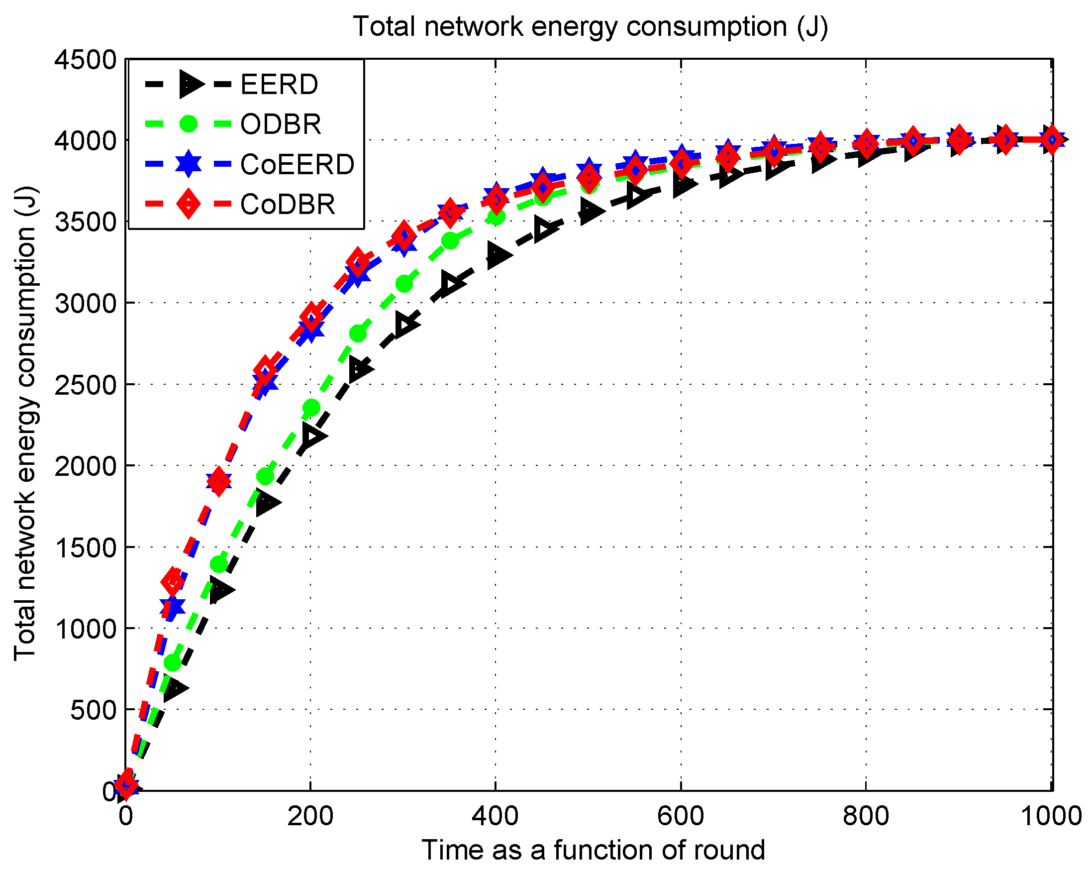
The comparison of EERD and CoEERD with the CoDBR and ODBR is shown in Figure 10. The total network consumed energy of the EERD is minimum as compared to all the schemes. The lowest distance parameter in EERD scheme reduces the energy consumption. Node nearest to the sink with the maximum energy and minimum BER is selected as a DSN. In EERD, minimum number of nodes are contributed in information forwarding. The ODBR scheme considers only the depth criteria for the selection of best RLN, which does not guarantee low consumption of energy. The proposed CoEERD scheme is a cooperative-based scheme, where the cooperation of single RLN with the DSN increases the node contribution during the packet broadcasting and results in high energy consumption as compared to the EERD. Moreover, the CoDBR scheme also uses cooperation and considers only the depth information for the selection of data advancer node. The cooperation of two RLNs with the DSN in CoDBR scheme, increases the energy consumption. At round 400, the CoDBR, CoEERD, and ODBR schemes consume high energy and have the values of consumed energy approximately 3500 J and 3400 J, respectively. At the same number of rounds, the proposed EERD scheme consumes 3100 J energy, which shows that the EERD scheme saves the network energy.

5.2. RODP or Packet Delivery Ratio (PDR)

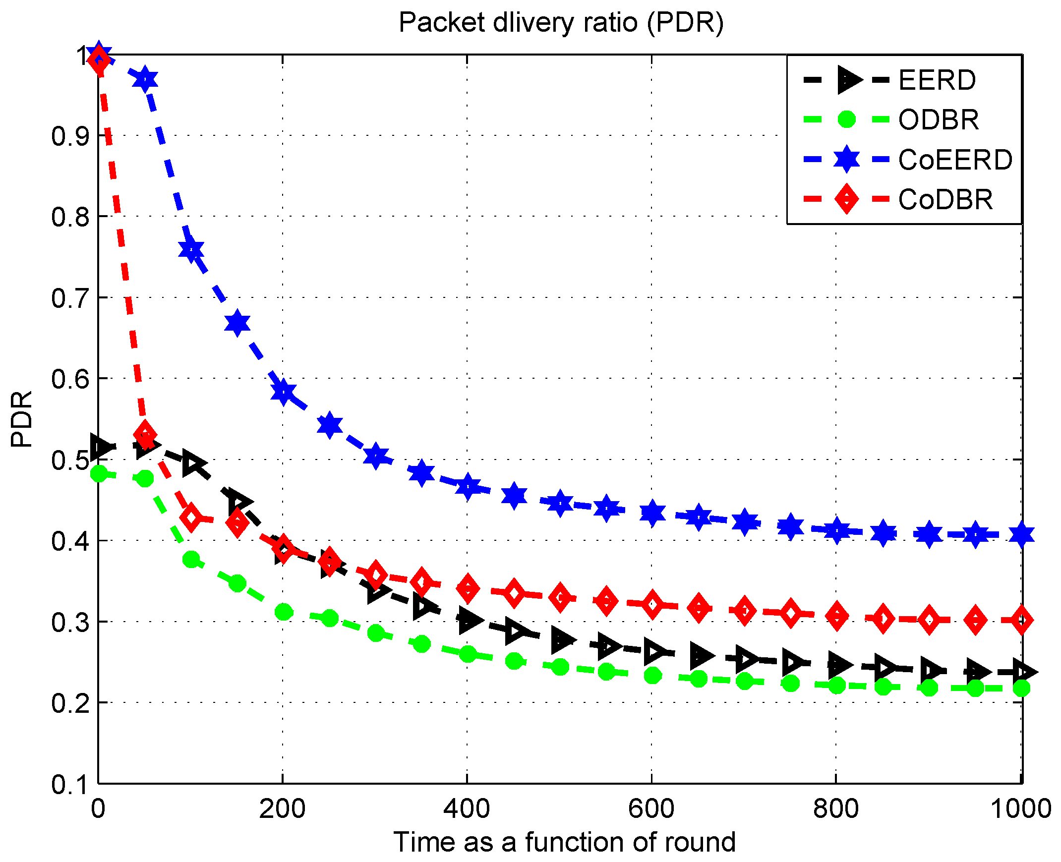
Figure 11 indicates that the RODP or PDR of the CoEERD scheme is higher than the CoDBR, EERD, and ODBR schemes. The reason of achieving high RODP of the CoEERD scheme is the avoidance of the adverse channel effects by looking at reduced BER. In addition, it uses the function parameters of highest residual energy and lowest distance for the selection of RLN and DSN. The cooperation of the single RLN node with the DSN in the CoEERD scheme reduces the number of contributing nodes, which consumes minimum energy and they remain alive for a long time to forward the packets. The CoDBR scheme uses two RLNs with the DSN, which consumes high energy and drains its battery power at a quicker rate, so the results show decreased RODP. The EERD is non-cooperative scheme, which achieves low RODP value due to the single best forwarder node as compared to the cooperative schemes. The ODBR scheme is also a non-cooperative scheme which decreases the RODP by forwarding the information over single path. Initially, the CoEERD, and CoDBR schemes with the same value of RODP that starts from 1, while the EERD and ODBR schemes start from 0.5. From start to end, the CoEERD scheme has the maximum RODP as compared to all of the schemes, while the CoDBR scheme has the higher RODP value than the EERD and ODBR schemes from start to round 100, and for some instant it decreases due to long transmission path. Moreover, at round 400, the RODP values of the CoDBR, EERD, and ODBR schemes are 0.38, 0.35 and 0.25, respectively, while at the same round, the CoEERD has high RODP value nearer to 0.5, which ensures a reliable network.

5.3. Total Delay of the Network

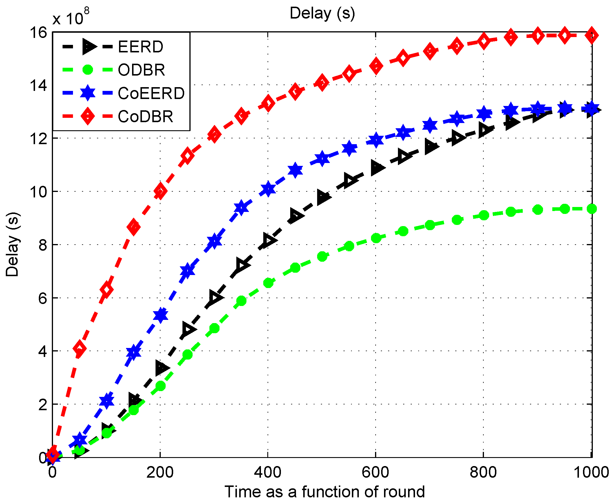
The comparison of the total delay of the network is plotted in Figure 12. The reason for producing higher delay in the CoDBR scheme is the cooperation of two RLNs with the DSN, which consumes extra time during best forwarder nodes selection and packet transmission. The CoEERD scheme uses single RLN with the DSN, which consumes less than CoDBR. In addition, the calculation of function parameters in EERD and CoEERD has more computation time that shoots up their delay than ODBR. The ODBR scheme considers only depth information for the best relay selection, which lowers delay in proceeding information. At round 400, the ODBR scheme produces lower delay than the rest of the other schemes and its value is 6 × 10 8 seconds. The EERD and CoEERD provide the second and third smallest delay values with magnitude of 8 × 10 8 and 10 × 10 8 seconds, respectively. At this time, the value of delay of CoDBR scheme is 16 × 10 8 seconds.

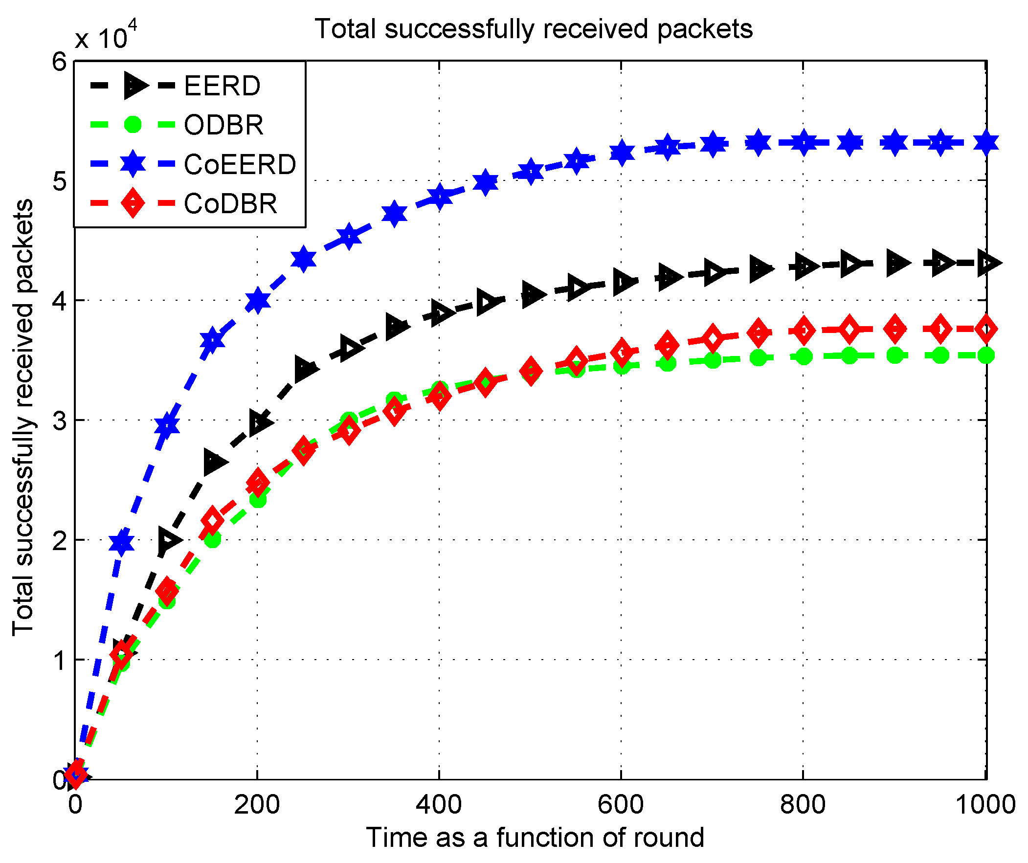
5.4. Total Successfully Received Packets

Figure 13 indicates the comparison of total received information packets at the upper sink nodes. The ratio of information packet secured by the sink node of the CoEERD is higher than the EERD, CoDBR, and ODBR. The reason for this achievement is that the CoEERD scheme uses the weighting function parameters: highest residual energy, lowest BER and lowest distance which ensures the accuracy of the maximum information at the final DSN. The CoDBR scheme uses two RLNs during the cooperation with the DSN and considers only the depth or the selection of RLNs and DSN. The contribution of maximum nodes in CoDBR during the routing consumes maximum energy and retains the burden on the close-to-surface nodes, which die quickly and result in data loss. The ODBR is a non-cooperative scheme which loses maximum information in information proceeding. The EERD is also non-cooperative and considers the robust function parameters for the choice of data advancer node, which increases the possibility of the maximum packets received at the final DSN.

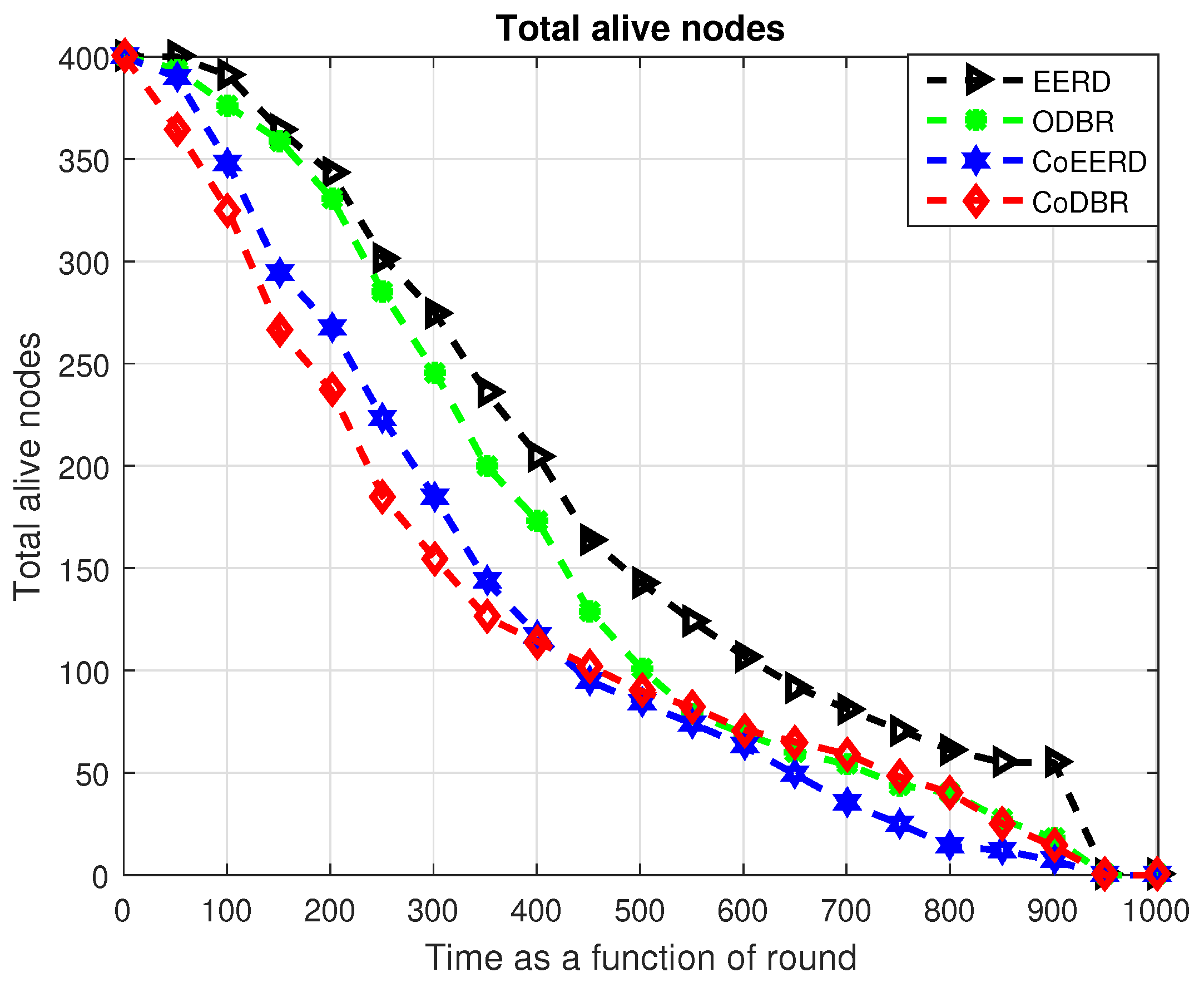
5.5. Total Alive Nodes of the Network

The plot of the alive nodes is indicated in Figure 14. The comparison shows that the rate of alive nodes of the EERD is higher than the all other schemes. The ODBR is the second scheme after EERD, which also keeps maximum nodes alive. The count of alive nodes of the CoEERD is higher than the CoDBR. The reason for this is the consumption of minimum energy. Secondly, the selection of the best forwarder node through the weighting function helps it to choose the node which forwards the packet with the cost of low energy consumption. The ODBR considers depth for the best relay, which also minimizes the energy consumption. The CoEERD uses single RLN with the DSN, it also consumes minimum energy as compared to the CoDBR. In CoDBR, the maximum nodes are involved in packet proceeding due to the cooperation of two RLNs with the DSN, which increases energy consumption and nodes die at the quicker rate. The total number of alive nodes, at round 400 in EERD are 200, ODBR and CoEERD have approximately 160 and 130 nodes alive at that time, respectively. During this time, CoDBR has 100 nodes alive. However, after round 400, nodes die quicker in CoEERD than the CoDBR, which is due to the lowest depth nodes of the CoEERD scheme getting burdened with data traffic.

6. Conclusion and Future Directions

This paper contains the design of two routing algorithms EERD and CoEERD for U-WSNs. The EERD minimizes the energy consumption, while the CoEERD improves the network reliability. Both schemes use data sender nodes based on the weighting function parameters (highest residual energy, lowest BER, and shortest distance). Based on these parameters and using a single-path routing, the EERD scheme saves the network energy and prolongs the network lifetime. However, it does not ensure packet reliability in harsh conditions due to the choice of the single path. For the network reliability, the proposed CoEERD scheme is designed. The scheme uses multi-path routing due to the cooperation of a single RLN. The same criterion is defined for the data forwarder nodes selection and cooperation is held among the RLN and DSN nodes. The SRN proceeds the packets to both the RLN and DSN nodes. In case the BER exceeds the threshold value at DSN, it requests the RLN that amplifies the packet and sends back towards the DSN along with ACK. For diversity, MRC is used to merge the two packets and transmit them towards the sink. The proposed schemes have presented the enriched performance in terms of the evaluated performance metrics. In future, strategies and mechanism will be devised to reduce the high delay due to the cooperation of nodes in CoEERD.

Author Contributions

U.U accomplished the proposition and implementation of the idea with A.K. as a supervisor. M.Z. and I.A. streamlined the overall manuscript while H.A.K. and I.U. responded to reviewers’ comments.

Funding

This research was funded in part by SEP-CONACyT Research Project under grant 255387, the School of Engineering and Sciences and the Telecommunications Research Group at Tecnologico de Monterrey, Monterrey, Mexico. This research work was also supported in part by the Faculty of Computer Science and Information Technology, University of Malaya, under Postgraduate Research Grant PG035-2016A.

Conflicts of Interest

The authors declare no conflict of interest.

Abbreviations

U-WSNsUnderwater wireless sensor networks
EERDEffective energy and reliable deliver routing
CoEERDCooperative effective energy and reliable deliver routing
ODBROptimized depth base routing
CoDBRCooperative depth base routing
RSSIReceived signal strength indicator
CSIChannel state information
PSDPower spectral density
RODPRatio-of-delivered packet
SNRSignal to noise ratio
MRCMaximal ratio combine
AFAmplifying and forward
T x Transmission range
BERBit error rate
RERResidual energy ratio
FLTFuzzy logic technique
ACKAcknowledgment
IDIdentification
DSNDestination node
CRCooperative routing
CPControl packet
RLNRelay node
RLNsRelay nodes
SRNSource node
NACKNegative acknowledgment
RFRadio frequency
DFDecode and forward
REQRequest send
E-2-EEnd-to-end

References

  1. Akyildiz, I.F.; Pompili, D.; Melodia, T. Underwater acoustic sensor networks: research challenges. Ad hoc Netw. 2005, 3, 257–279. [Google Scholar] [CrossRef]
  2. Jiang, Z. Underwater acoustic networks—Issues and solutions. Int. J. Intell. Control Syst. 2008, 13, 152–161. [Google Scholar]
  3. Wahid, A.; Lee, S.; Kim, D. A reliable and energy efficient routing protocol for underwater wireless sensor networks. Int. J. Commun. Syst. 2014, 27, 2048–2062. [Google Scholar] [CrossRef]
  4. Erol, M.; Vieira, L.F.; Gerla, M. Localization with Dive’N’Rise (DNR) beacons for underwater acoustic sensor networks. In Proceedings of the Second Workshop on Underwater Networks, Montreal, QC, Canada, 14 September 2007; pp. 97–100. [Google Scholar]
  5. Sozer, E.M.; Stojanovic, M.; Proakis, J.G. Underwater acoustic networks. IEEE J. Ocean. Eng. 2000, 25, 72–83. [Google Scholar] [CrossRef]
  6. Al-Dharrab, S.; Uysal, M.; Duman, T. Cooperative underwater acoustic communications [accepted from open call]. IEEE Commun. Mag. 2013, 51, 146–153. [Google Scholar] [CrossRef]
  7. Maqsood, H.; Javaid, N.; Zain-ul-Abidin, M.; Ejaz, M.; Shakeel, U. Energy balanced interference aware energy efficient depth base routing protocol for UWSNs. In Proceedings of the 2015 10th International Conference on Broadband and Wireless Computing, Communication and Applications (BWCCA), Krakow, Poland, 4–6 November 2015; pp. 13–19. [Google Scholar]
  8. Wahid, A.; Kim, D. An energy efficient localization-free routing protocol for underwater wireless sensor networks. Int. J. Distrib. Sens. Netw. 2012, 8, 307246. [Google Scholar] [CrossRef]
  9. Shah, M.; Javaid, N.; Imran, M.; Guizani, M.; Khan, Z.A.; Qasim, U. Interference aware inverse EEDBR protocol for underwater WSNs. In Proceedings of the 19th International Conference on Complex, Intelligent, and Software Intensive Systems (CISIS), Fukuoka, Japan, 6–8 July 2016; pp. 256–263. [Google Scholar]
  10. Khan, A.; Ejaz, M.; Javaid, N.; Azeemi, M.Q.; Qasim, U.; Khan, Z.A. EEORS: Energy Efficient Optimal Relay Selection Protocol for Underwater WSNs. In Proceedings of the 19th International Conference on Network-based Information System, Ostrava, Czech Republic, 7–9 September 2016; pp. 239–245. [Google Scholar]
  11. Khan, A.; Javaid, N.; Mahmood, H.; Sangeen; Khan, Z.A.; Qasim, U. EEORS: Energy Efficient Optimal Relay Selection Protocol for Underwater WSNs. In Proceedings of the 10th International Conference on Complex, INtelligent, and Software Intensive System, Fukuoka, Japan, 6–8 July 2016; pp. 264–270. [Google Scholar]
  12. Shah, S.; Khan, A.; Ali, I.; Ko, K.M.; Mahmood, H. Localization Free Energy Efficient and Cooperative Routing Protocols for Underwater Wireless Sensor Networks. Symmetry 2018, 10, 498. [Google Scholar] [CrossRef]
  13. Ahmed, T.; Chaudhary, M.; Kaleem, M.; Nazir, S. Optimized depth-based routing protocol for underwater wireless sensor networks. In Proceedings of the 2016 International Conference on Open Source Systems Technologies (ICOSST), Lahore, Pakistan, 15–17 December 2016; pp. 147–150. [Google Scholar]
  14. Nasir, H.; Javaid, N.; Ashraf, H.; Manzoor, S.; Khan, Z.A.; Qasim, U.; Sher, M. CoDBR: Cooperative depth based routing for underwater wireless sensor networks. In Proceedings of the 2014 Ninth International Conference on Broadband and Wireless Computing, Communication and Applications, Guangdong, China, 8–10 November 2014; pp. 52–57. [Google Scholar]
  15. Bu, R.; Wang, S.; Wang, H. Fuzzy logic vector-based forwarding routing protocol for underwater acoustic sensor networks. Trans. Emerg. Telecommun. Technol. 2018, 29, e3252. [Google Scholar] [CrossRef]
  16. Xie, P.; Cui, J.H.; Lao, L. VBF: Vector-based forwarding protocol for underwater sensor networks. In International Conference on Research in Networking; Springer: Berlin/Heidelberg, Germany, 2006; pp. 1216–1221. [Google Scholar]
  17. Pappas, N.; Dimitriou, I.; Chen, Z. Network-level cooperation in random access iot networks with aggregators. In Proceedings of the 2018 30th International Teletraffic Congress (ITC 30), Vienna, Austria, 3–7 September 2018; Volume 1, pp. 245–253. [Google Scholar]
  18. Javaid, N.; Hussain, S.; Ahmad, A.; Imran, M.; Khan, A.; Guizani, M. Region based cooperative routing in underwater wireless sensor networks. J. Netw. Comput. Appl. 2017, 92, 31–41. [Google Scholar] [CrossRef]
  19. Javaid, N.; Ejaz, M.; Abdul, W.; Alamri, A.; Almogren, A.; Niaz, I.; Guizani, N. Cooperative Position Aware Mobility Pattern of AUVs for Avoiding Void Zones in Underwater WSNs. Sensors 2017, 17, 580. [Google Scholar] [CrossRef]
  20. Pappas, N.; Kountouris, M.; Jeon, J.; Ephremides, A.; Traganitis, A. Effect of energy harvesting on stable throughput in cooperative relay systems. J. Commun. Netw. 2016, 18, 261–269. [Google Scholar] [Green Version]
  21. Sajid, M.; Wahid, A.; Pervaiz, K.; Khizar, M.; Khan, Z.A.; Qasim, U.; Javaid, N. SMIC: Sink mobility with incremental cooperative routing protocol for underwater wireless sensor networks. In Proceedings of the 10th International Conference on Complex, Intelligent, and Software Intensive Systems (CISIS), Fukuoka, Japan, 6–8 July 2016; pp. 256–263. [Google Scholar]
  22. Ghoreyshi, S.; Shahrabi, A.; Boutaleb, T. A novel cooperative opportunistic routing scheme for underwater sensor networks. Sensors 2016, 16, 297. [Google Scholar] [CrossRef] [PubMed]
  23. Shah, P.M.; Ullah, I.; Khan, T.; Hussain, M.S.; Khan, Z.A.; Qasim, U.; Javaid, N. MobiSink: cooperative routing protocol for underwater sensor networks with sink mobility. In Proceedings of the 2016 IEEE 30th International Conference on Advanced Information Networking and Applications (AINA), Crans-Montana, Switzerland, 23–25 March 2016; pp. 189–197. [Google Scholar]
  24. Umar, A.; Akbar, M.; Iqbal, Z.; Khan, Z.A.; Qasim, U.; Javaid, N. Cooperative partner nodes selection criteria for cooperative routing in underwater WSNs. In Proceedings of the 5th National Symposium on Information Technology: Towards New Smart World (NSITNSW), Riyadh, Saudi Arabia, 17–19 February 2015; pp. 1–7. [Google Scholar]
  25. Wang, F.-Y.; Gildea, K.; Jungnitz, H.; Chen, D.D. Protocol design and performance analysis. IEEE Trans. Inf. Theory 2007, 53, 3677–3696. [Google Scholar]
  26. Khan, A.; Altowaijri, S.M.; Ali, I.; Rahman, A.U. Reliability-aware cooperative routing with adaptive amplification for underwater acoustic wireless sensor networks. Symmetry 2019, 11, 421. [Google Scholar] [CrossRef]
  27. Khan, A.; Ahmedy, I.; Anisi, M.; Javaid, N.; Ali, I.; Khan, N.; Alsaqer, M.; Mahmood, H. A localization-free interference and energy holes minimization routing for underwater wireless sensor networks. Sensors 2018, 18, 165. [Google Scholar] [CrossRef] [PubMed]
  28. Mackenzie, K.V. Nine term equation for sound speed in the oceans. J. Acoust. Soc. Am. 1981, 70, 807–812. [Google Scholar] [CrossRef]
  29. Hasna, M.O.; Alouini, M.S. End-to-end performance of transmission systems with relays over Rayleigh-fading channels. IEEE Trans. Wirel. Commun. 2003, 2, 1126–1131. [Google Scholar] [CrossRef]
  30. Khan, A.; Javaid, N.; Ali, I.; Anisi, M.H.; Rahman, A.U.; Bhatti, N.; Zia, M.; Mahmood, H. An energy efficient interference-aware routing protocol for underwater WSNs. KSII Trans. Internet Inf. Syst. 2017, 11, 4844–4864. [Google Scholar]
  31. Khan, A.; Anisi, M.H.; Ali, I.; Javaid, N.; Azeem, M.Q.; Mahmood, H. An energy efficient interference and route aware protocol for underwater wireless sensor networks. Ad Hoc Sens. Wirel. Netw. 2018, 41, 31–53. [Google Scholar]
  32. Khan, A.; Ali, I.; Ghani, A.; Khan, N.; Alsaqer, M.; Rahman, A.; Mahmood, H. Routing protocols for underwater wireless sensor networks: Taxonomy, research challenges, routing strategies and future directions. Sensors 2018, 18, 1619. [Google Scholar] [CrossRef]
  33. Majid, A.; Azam, I.; Waheed, A.; Zain-ul-Abidin, M.; Hafeez, T.; Khan, Z.A.; Qasim, U.; Javaid, N. An energy efficient and balanced energy consumption cluster based routing protocol for underwater wireless sensor networks. In Proceedings of the IEEE 30th International Conference on Advanced Information Networking and Applications (AINA), Crans-Montana, Switzerland, 23–25 March 2016; pp. 324–333. [Google Scholar]
  34. Nasir, H.; Javaid, N.; Murtaza, M.; Manzoor, S.; Khan, Z.A.; Qasim, U.; Sher, M. ACE: Adaptive cooperation in EEDBR for underwater wireless sensor networks. In Proceedings of the 2014 Ninth International Conference on Broadband and Wireless Computing, Communication and Applications, Guangdong, China, 8–10 November 2014; pp. 8–14. [Google Scholar]
  35. Vakily, V.T.; Jannati, M. A new method to improve performance of cooperative underwater acoustic wireless sensor networks via frequency controlled transmission based on length of data links. Wirel. Sens. Netw. 2010, 2, 381. [Google Scholar] [CrossRef]
  36. Chong, P.K.; Kim, D. Surface-level path loss modeling for sensor networks in flat and irregular terrain. ACM Trans. Sens. Netw. (TOSN) 2013, 9, 15. [Google Scholar] [CrossRef]
  37. Urick, R.J. Principles of Underwater Sound for Engineers; Tata McGraw-Hill Education: New Delhi, India, 1967. [Google Scholar]
  38. El-Darymli, K. Amplify-and-forward cooperative relaying for a linear wireless sensor network. In Proceedings of the IEEE International Conference on Systems Man and Cybernetics (SMC), Istanbul, Turkey, 10–13 October 2010; pp. 106–112. [Google Scholar]
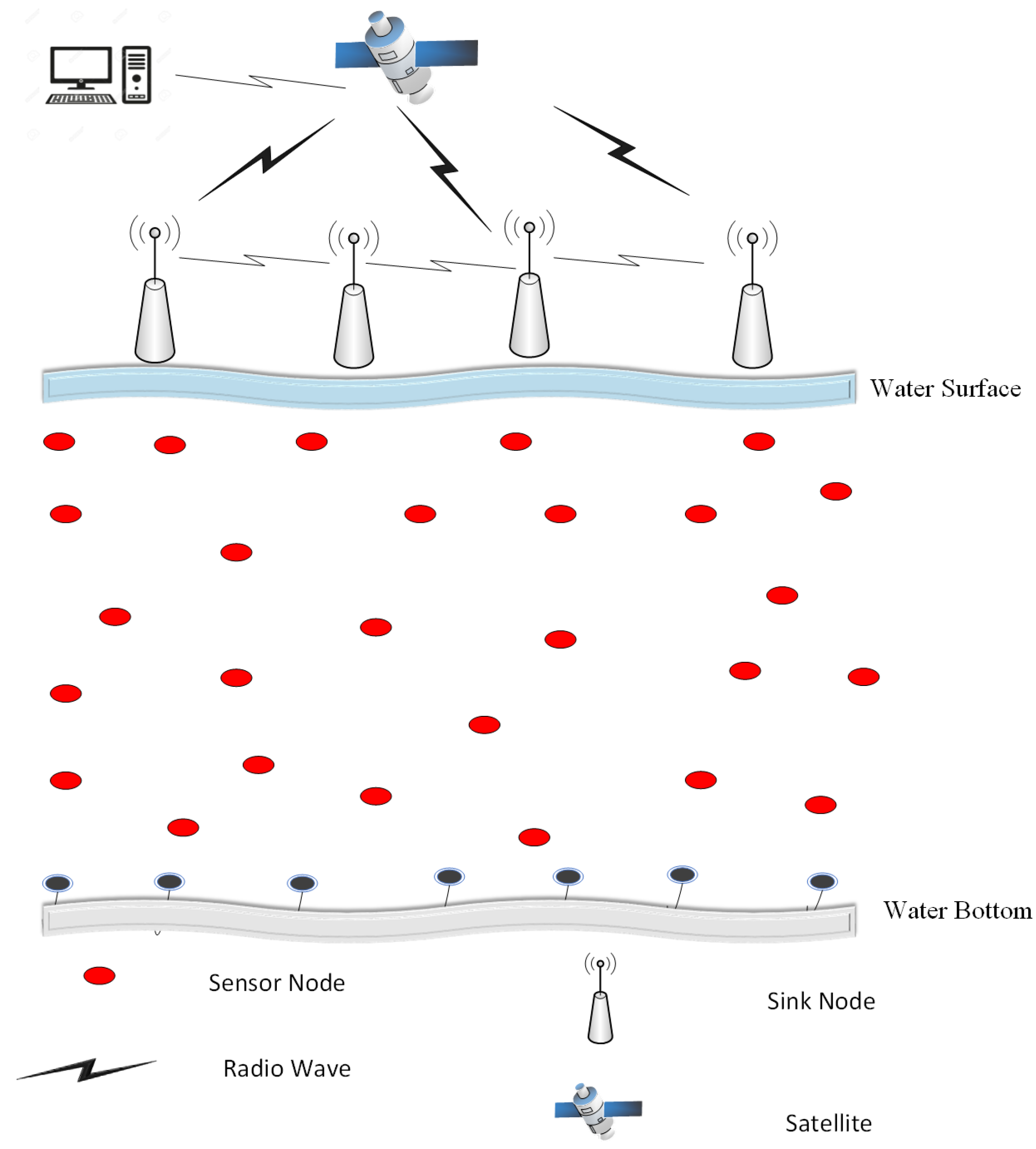
Figure 1. Network Model.
Energies 12 02630 g001
Figure 2. Control packet (CP) format.
Energies 12 02630 g002
Figure 3. Data forwarding in EERD scheme.
Energies 12 02630 g003
Figure 4. Source and destination with optimal relay table.
Energies 12 02630 g004
Figure 5. Flow chart of EERD scheme.
Energies 12 02630 g005
Figure 6. ACK, NACK, and REQ scenario.
Energies 12 02630 g006
Figure 7. Cooperation model.
Energies 12 02630 g007
Figure 8. MRC Model.
Energies 12 02630 g008
Figure 9. Flow chart of the CoEERD scheme.
Energies 12 02630 g009
Figure 10. Initial energy available for 1000 rounds.
Energies 12 02630 g010
Figure 11. RODP.
Figure 11. RODP.
Energies 12 02630 g011
Figure 12. Total delay of the network.
Energies 12 02630 g012
Figure 13. Total Packets Received at Sink Node.
Energies 12 02630 g013
Figure 14. Total number of alive nodes.
Energies 12 02630 g014
Table 1. Overview of the recently published schemes.
CitationsYear      Technique UsedAdvantagesShortcoming
[15]2018Single-path routing scheme, data forwarder nodes are selected by considering the node position, residual energy, and fuzzy logic technique.Minimizes the latency, consumes low energy.Due to single-path routing loses the reliability.
[17]2018Cooperative base scheme, aggregators to forward the packets in random manner.The work deals with delay and increase network throughput.The use of aggregators makes the network complex.
[18]2017Region base non-cooperative algorithm, uses the sink mobility in vertical and horizontal directions, considers lowest depth, SNR, and highest residual energy for best relay selection.Balances network energy consumption, retains maximum nodes alive.Loses the reliability and drops maximum packets.
[19]2017Both the cooperative and non-cooperative schemes used the node position information by considering distance and mobile sinks for information advancement.To overcome the void space problem in the network, decreases latency, and increases the throughput.Consumes maximum energy due to the deficiency of the balanced energy technique.
[20]2016Cooperative base routing scheme, Used an energy harvesting technique on the source and relay node.The scheme maximizes the network throughput and ensure reliability due to cooperation.The network is complicated and increase the network delay.
[21]2016Cooperative single relay scheme, highest residual energy, lowest depth, and channel consideration is used for data forwarder nodes selection.Improves the network reliability, forwards maximum information towards the sink node, reduces delay.Consumes high energy, nodes die quickly, loss accuracy.
[22]2016Cooperative base routing schemes, uses the least number of neighbor and distance for best forwarder node selection, uses MRC technique for diversity.Balance energy consumption, prolong the network, enhances the PDR.Render high latency during the packet advancement, loss the data accuracy.
[23]2016 Cooperative base scheme, single relay used with DN, Uses four mobile sink nodes, for diversity use MRC technique.Due to sink mobility reduces the delay, balance energy consumption, retains maximum nodes alive.it blindly selects the channel link for transmission data which affects the PDR.
[13]2016Non-cooperative base routing scheme, used a region base network.Saves the network energy, maximizes the network life-span.Reduces the network reliability drop maximum packets.
[24]2015Cooperative routing scheme, for best forwarder nodes selection considers the lowest distance and lowest SNR value.Maximize the throughput, enhances the network reliability, ensure data accuracy.Lowest depth node dies quickly, increase the latency, consumes maximum energy.
[14]2014Cooperative single relay scheme, best forwarder nodes are selected by considering the weight function, use MRC technique.Ensures data accuracy, improves the link quality, reduces the channel affects.Consumes high energy, nodes die quickly.
[25]2007Cooperative-based routing scheme, used cognitive multiple access instead of conventional relaying technique.The scheme deal with the latency and maximize the network throughput.Nodes in the network consume high energy.
Table 2. Parameters used for simulation.
ParametersValues
Total sensors nodes400
Total sink nodes4
Deployment area width500 m
Deployment area depth500 m
Data packet size1000 bits
Wind speed10 m/s
Control packet size48 bits
Idle mode exhaust power10 mW
Transmission power2 W
Reception power0.5 W
Initial energy available for 1000 rounds10 J
Transmission range100 m
Bandwidth30,000 Hz