Abstract
The scheme based on direct torque and flux control (DTFC) as well as active flux is a good choice for the interior permanent magnet synchronous motor (IPMSM) sensorless control. The precision of the stator flux observation is essential for this scheme. However, the performance of traditional observers like pure integrator and the low-pass filter (LPF) is severely deteriorated by disturbances, especially dc offset. Recently, a sliding-mode stator flux observer (SMFO) was proposed to reduce the dc offset in the estimated stator flux. However, it cannot eliminate the dc offset totally and will cause the chattering problem. To solve these problems, a novel super-twisting sliding-mode stator flux observer (STSMFO) is proposed in this paper. Compared with SMFO, STSMFO can reduce the chattering and fully eliminate the dc offset without any amplitude and phase compensation. Then, the precision of the stator flux and rotor position can be greatly improved over a wide speed region. The detailed mathematical analysis has been given for comparing it with another three traditional observers. The numerical simulations and experimental testing with an IPMSM drive platform have been implemented to verify the capability of the proposed sensorless scheme.
1. Introduction
Interior permanent magnet synchronous motor (IPMSM) has been utilized in wide industrial fields because of its advantages like high torque density, fast response, and low torque ripple [1,2,3]. Direct torque control (DTC) is one of the most popular strategies for ac machines for its fast torque response and strong robustness [4,5]. However, the traditional DTC relies on the hysteresis comparators and the switching table, which will result in the unfixed switching frequency and the inaccurate compensation of the flux magnitude and the torque error. Furthermore, the ripple will be caused by the hysteresis comparators in the stator flux, and ripple can deteriorate the performance of the IPMSM drive [6]. To overcome this problem, the space vector modulation (SVM) is introduced into the DTC algorithm and the DTC-SVM is proposed [7]. The reference voltage is selected via three variables which are torque error, reference stator flux amplitude, and feedback flux vector, respectively. The introduction of the SVM can fix the switching frequency and reduce the ripple. However, the robustness is poor due to the single torque closed-loop structure of the DTC-SVM. In [8], the direct torque and flux control (DTFC) is proposed to enhance the robustness of the DTC-SVM. Compared with the DTC-SVM, one extra proportional-integral (PI) regulation is utilized to control flux and it can realize the flux to track the flux reference more precisely.
For the sake of realizing the high-performance control of IPMSM, the accurate position information is essential. However, position sensors not only decrease the reliability of the IPMSM system but also increase the cost. Therefore, research of the sensorless strategies for PMSMs have been paid much attention. In general, sensorless methods are divided into two categories which are based on signal injection and machine model according to speed region. At low speeds, the signal injection is generally adopted to realize rotor estimation [9,10,11]. However, it can cause the extra loss and torque ripple. With the speed increasing to the medium domain, model-based schemes are widely utilized to observe the position [12,13,14,15,16]. Due to its ease of implementation, plenty of research is focused on the designation of the back-emf observer like the extended Kalman filter [12] and the sliding-mode observer (SMO) [13]. However, the capability of the back-emf-based sensorless scheme is poor at low speeds because of the non-negligible noise. In [17], the active flux concept is proposed to transform salient-pole motors into virtual nonsalient-pole motors. The active flux is independent of speed and the direction aligns with rotor direction. Therefore, the active flux-based sensorless scheme can be readily implemented. Even at low speeds, the sensorless control can be carried out without signal injection [18]. Moreover, the stator flux can be observed by the DTFC and the corresponding robustness is enhanced due to the regulation of the DTFC. Therefore, the active flux-based sensorless scheme is suitable for the DTFC-based IPMSM drive system
Based on the IPMSM model, the stator flux is the integral of the back-emf and it is critical for flux observers to consider the influence of disturbances, especially dc offset [19]. When the pure integrator is adopted as a flux observer, the flux dc offset will increase with time, eventually resulting in the saturation of the observer [20]. In [21], a disturbance observer is designed to eliminate the dc component, but it is difficult to implement due to its complex structure. In [22], the dc component of the back-emf is filtered out by a low-pass filter (LPF). Actually, the LPF is a pure integrator cascaded with a high-pass filter. However, the amplitude attenuation and the phase delay are inevitable because of the introduction of the LPF. Therefore, the accurate compensation is essential for the sensorless control scheme. In [23], the SMFO is proposed to observe the stator flux without compensation, which is robust against disturbances and can reduce the dc offset through its compensation term. However, the dc disturbance rejection capability of the SMFO is limited and the chattering problem of the traditional SMFO is inevitable. It is worth mentioning that even a little dc offset can cause serious speed ripples. In [24], super-twisting algorithm (STA) is proposed to decrease the chattering of the SMO without reducing the robustness and it has been widely utilized in observers and controllers [25,26,27,28].
This paper proposed a novel STSMFO for the active flux-based IPMSM sensorless scheme. The stator flux observer based on STA is designed to overcome the disadvantages of the traditional observer, including the saturation effect, the position compensation, and flux dc offset. The corresponding Lyapunov stability of the STSMFO is proved based on references [29,30]. Then, the precision of the flux and position estimation can be greatly enhanced over a wide speed region. Moreover, the proposed sensorless method is better than most model-based sensorless strategies at low speeds due to the fact that it can be successfully utilized at low speeds without signal injection and compensation. Finally, the capability of the scheme based on the novel STSMFO is confirmed through numerical simulation and experimental testing with an IPMSM drive platform.
This paper is organized as follows: Section 2 gives the IPMSM model and the concept of DTFC. Section 3 introduces the active flux-based sensorless strategy and the mathematical analysis of three traditional observers. Section 4 introduces the proposed STSMFO and its analysis. The evaluation of the simulation and the experiment is given in Section 5. Section 6 draws the conclusions.
2. Direct Torque and Flux Control
Figure 1 shows the relationship between the stator flux-oriented coordinate (x-y), rotating reference coordinate (d-q), and stationary reference coordinate (α-β). The IPMSM stator flux and voltage equations in the d-q axis are presented as:
where, udq, idq, and ψdq are the stator voltages, currents, and flux linkages in the d-q axis, respectively. RS is the resistance, Ldq are the stator inductances, ωe is the rotor electrical angular velocity, ψf is the rotor flux linkage, δ is the load angle, θe is the rotor electrical position, and θs is the stator flux angle.
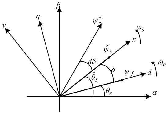
Figure 1.
The relationship between various reference frames.
Transforming (1) to an x-y reference frame and combining the relationship between load angle and torque [31], the voltage equation is found as:
where, , pn is the number of pole pairs, ψs is the stator flux vector, and uxy and ixy are the stator voltages and currents in the x-y frame, respectively.
The IPMSM stator flux and torque equations in the α-β axis can be given as:
where, uαβ, iαβ, and ψαβ are the α-β axis stator voltages, currents, and flux linkages respectively, and Te is torque.
3. Active Flux-Based Sensorless Control
To observe the rotor position of IPMSMs easily, the active flux is proposed to transform IPMSMs into virtual nonsalient-pole machines. The d-q axis active flux equation in reference [17] is given as:
where, ψdqAF are the active fluxes in the d-q axis. Equation (7) shows that the active flux aligns with the rotor direction, therefore active flux in the α-β frame results in:
where, ψαβAF are the active fluxes in the α-β axis. Equation (8) shows that the rotor position can be observed via the active flux vector. One way to extract it is a phase-locked loop. Moreover, it is worth mentioning that the active flux is obtained on the basis of stator flux. Therefore, the accuracy of the rotor position observation directly relies on the estimation accuracy of stator flux. In practice, a dc component in back-emf is inevitable and it is the main reason for the deteriorating performance of the flux observer. Considering the dc component, the stator flux equation is presented as:
where us and is are the stator voltage and current, A0 is the dc component, and es is the back-emf. For the convenience of analysis, es is expressed as:
where, is the fundamental component. A1, ω1, and are amplitude, angular frequency, and initial angel of the fundamental component, respectively. Taking the Laplace transformation of back-emf, it can be found as:
where, Es(s) is the Laplacian form of es and s is the Laplacian operator.
3.1. Pure Integrator-Based Observer
The Laplace transform of pure integrator is given as:
where, ψs_I(s) is the Laplacian form of ψs_I, and ψs_I is the pure integrator-observed stator flux. Taking (11) into (12) then results in [19]:
As seen, two disturbance terms exist in the estimated stator flux by pure integrator. One is a component increasing with time linearly, which is caused by a dc component in the back-emf and it can eventually result in the saturation of the integrator. Another one is a dc offset determined by the fundamental wave and it will change at various initial positions. These two terms can cause serious distortions of the estimated stator flux. Furthermore, the precise rotor position estimation cannot be achieved due to the distorted active flux.
3.2. Low-Pass Filter (LPF)-Based Observer
For the sake of filtering out the dc component in the back-emf, a high-pass filter is used to cascade with pure integrator. The Laplace transform of the observer is found as:
which shows that the observer is actually a LPF. In Equation (14), ψs_LPF(s) is the Laplace transform of ψs_LPF, ψs_LPF and ωc are the estimated stator flux and cutoff frequency of LPF, respectively. ωc is always selected much lower than ω1 because it is, in effect, the cutoff frequency of the high-pass filter. Taking (11) into (14) then results in [19]:
where, θ1 = tan−1(ωc/ω1) is the phase delay caused by the LPF. Compared with Equation (13), the component causing integrator saturation is removed. The two main distorted terms decrease exponentially to zero with time. Although the dc offset still cannot be eliminated totally, it is already decreased greatly by LPF. However, the phase delay θ1 and amplitude attenuation of the fundamental wave is inevitable because of the introduction of the LPF. Therefore, the estimated rotor position by LPF needs precise compensation to ensure good performance of the sensorless control.
3.3. First-Order Sliding-Mode Stator Flux Observer (SMFO)
Obviously, no matter whether a pure integrator-based observer or LPF-based observer is used, it cannot achieve high-performance sensorless control. Consequently, the SMFO is proposed to observe the stator flux. Figure 2 shows the diagram of the SMFO.
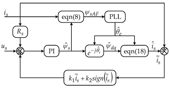
Figure 2.
The diagram of the first-order sliding-mode stator flux observer (SMFO).
The SMFO, considering both the current and the voltage model of IPMSM, is designed. Moreover, the former is essentially utilized to compensate the latter. The stator flux and current are defined as the state variable and the output, respectively. On the basis of the IPMSM model, equations of the SMFO result in:
where, is the stator current estimation error, ”^” is the estimated value, and sign () is the sign function. k1 and k2 are linear and nonlinear gains of the SMFO which affect the dynamic performance and robustness, respectively. The Lyapunov stability has been proved in reference [8]. Considering the dc offset, (16) can be found as:
Actually, the SMFO is used to observe the dc offset according to the current estimation error. Further, the estimated dc offset is fed back to the back-emf to realize the accurate estimation of the stator flux. However, the SMFO cannot remove flux dc offset totally. In the steady state, and the effect of the dc component on the flux estimation is eliminated. However, in the process of reaching a steady state, the estimated flux dc offset is already accumulated. The estimated flux dc offset can be given as:
where, ψs0 is the flux dc offset, and t1 is the time to steady state. In general, ψs0 can be omitted because A0 and t1 are small, but if new dc disturbances interfere with the system, it will cause the accumulation of flux estimation dc offset and eventually have a non-negligible impact on the stator flux observation.
4. Super-Twisting Sliding-Mode Stator Flux Observer
The estimation precision of the stator flux dramatically affects the capability of the DTFC-based active flux sensorless scheme. The first-order SMFO can observe the stator flux without phase shift and amplitude attenuation. However, the conventional first-order SMFO is still sensitive to dc disturbances and suffers from the chattering problem. To overcome the limitations of the first-order SMFO, the well-known STA was utilized to design an observer for estimating stator flux in this paper. With the STA, the chattering can be reduced and the dc offset can be eliminated effectively.
4.1. Super-Twisting Algorithm
To improve the chattering problem of the traditional SMO, the super-twisting algorithm was proposed in reference [24]. The equation of STA considering perturbation terms can be presented as:
where, xi, , ki and ρi are state variables, state variables estimation error, gains of the STA, and perturbation terms, respectively. The Lyapunov stability has been proved in references [29,30]. According to [29,30], the observer is stable when sliding-mode gains and the perturbation terms satisfy (22):
where, δ1 is a positive constant.
4.2. Super-Twisting Sliding-Mode Stator Flux Observer
To solve problems of chattering and the dc offset in the traditional SMFO, a stator flux observer is proposed based on STA. Substituting into (21), then Equation (21) can be rewritten as:
where, is:
Taking (24) into (22) results in:
which shows that the system can converge in finite time to sliding surface for a large enough δ1. By subtracting (23) from (4), the flux error equation is found as:
At the starting point, the stator flux estimation value is different from the actual value due to the existence of dc offset A0. Then, the sliding-mode terms are used to estimate the dc component. Furthermore, the estimated dc component is fed back to compensate the back-emf. At a steady state, the flux error is on the sliding surface. Taking into (26) results in:
which shows that the effect of the dc component has been removed. In addition, in the process of reaching the steady state, the accumulated flux estimation dc offset can be given as:
As we all know, the integral term will remain until the ψs0_STA is zero. Therefore, compared with the SMFO, the chattering caused by the sign function can be reduced greatly and the estimated flux dc offset can be eliminated completely due to the integral term and a large gain k2 of the STSMFO. In addition, it is worth mentioning that the stator flux amplitude reference value and estimated flux angle are utilized to replace the actual stator flux vector. The diagram of the STSMFO is shown in Figure 3.
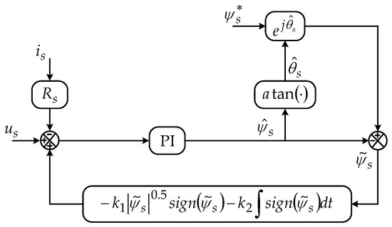
Figure 3.
The diagram of the super-twisting sliding-mode stator flux observer (STSMFO).
In conclusion, two disturbance terms by pure integrator can cause serious distortions of the estimated stator flux. The LPF can eliminate the dc offset at the cost of amplitude attenuation and phase shift. The SMFO can reduce the dc offset greatly without any influence on the fundamental wave. However, the SMFO will accumulate the small disturbance and cause chattering. Finally, the proposed STSMFO can remove the dc offset completely and smooth the estimated stator flux.
5. Evaluation via Simulation and Experiment
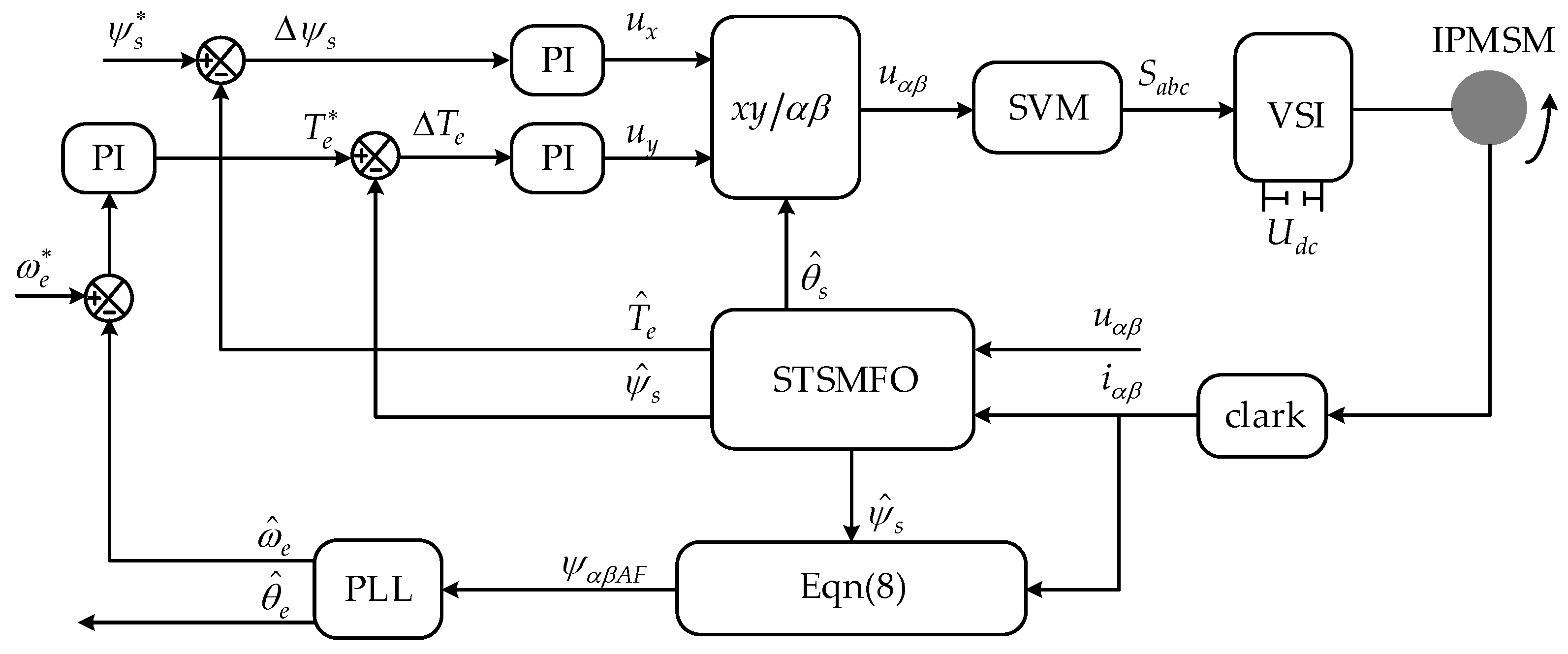
The IPMSM control scheme is given in Figure 4. Both the simulation and the experiment based on Figure 4 were carried out to verify the capability of the STSMFO. The parameters of the IPMSM are listed in Table 1.
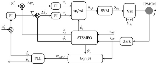
Figure 4.
The proposed interior permanent magnet synchronous motor (IPMSM) sensorless scheme.

Table 1.
IPMSM Parameters.
5.1. Simulation Results
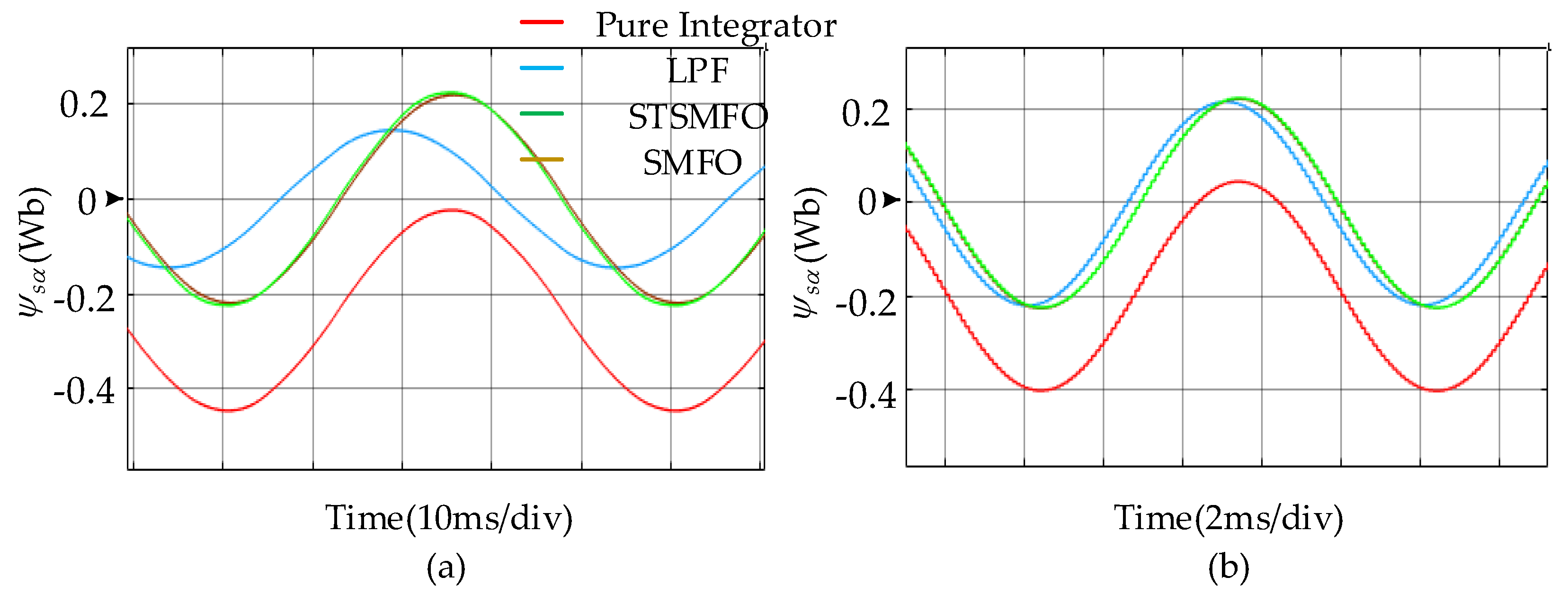
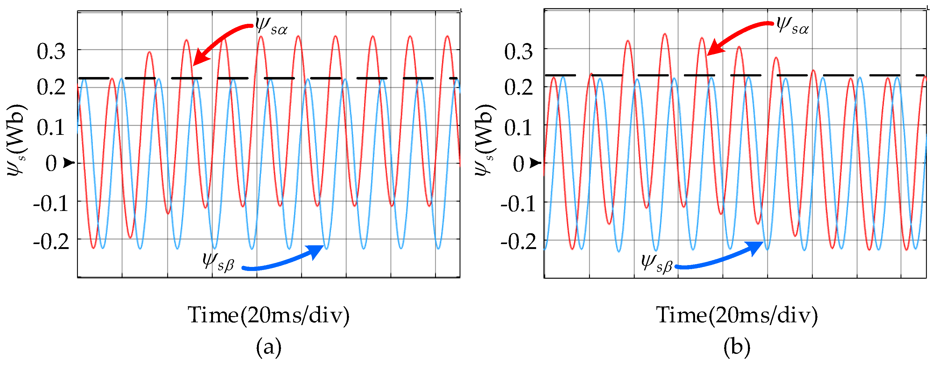
MATLAB/Simulink software was utilized to numerically demonstrate the capability of the STSMFO. The simulation results of α-axis estimated stator fluxes at 300 rpm and 1500 rpm are given in Figure 5.
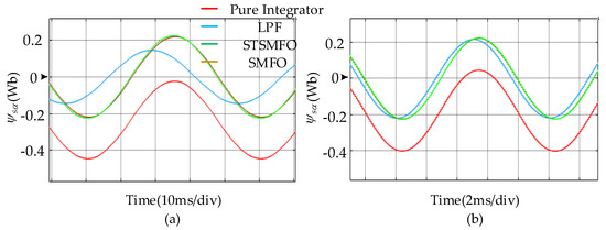
Figure 5.
Simulation results of α-axis estimated stator fluxes: (a) The stator fluxes at 300 rpm, (b) The stator fluxes at 1500 rpm.
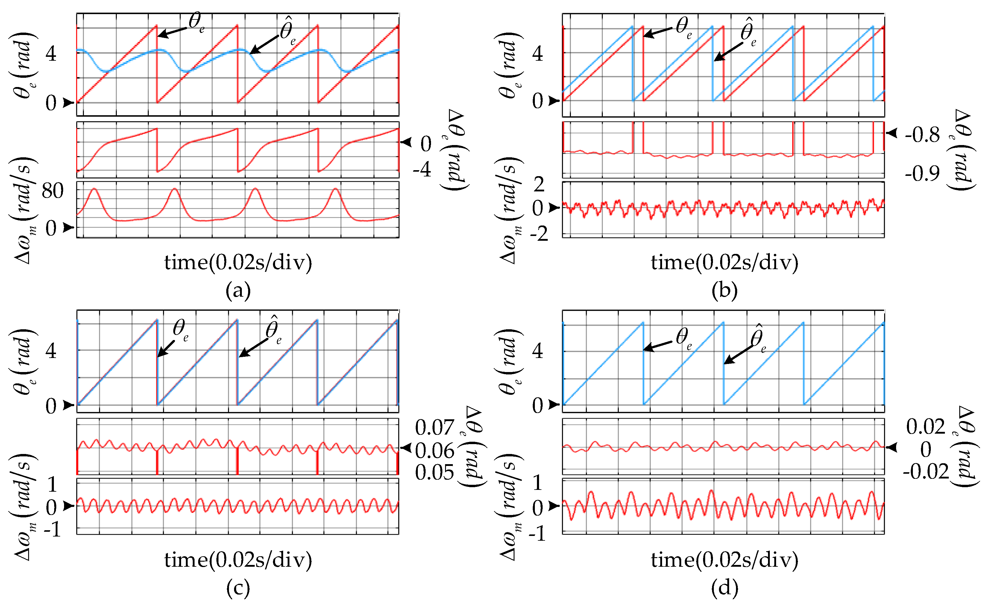
The pure integrator estimated stator flux deviates from the ideal value due to the dc offset. Figure 5a,b shows that the LPF will delay the phase and attenuate the amplitude of flux estimation. Moreover, as previously analyzed, the problems have been improved with the increase of the frequency of the fundamental wave. The simulation result of the rotor position observation at 300 rpm is shown in Figure 6 which shows that the pure integrator cannot estimate the rotor position correctly. In addition, the estimation error of the STSMFO is 0.01 rad which is lower than 0.06 rad of the SMFO and much lower than 0.85 rad of the LPF.
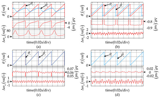
Figure 6.
The simulation result of the position observation at 300 rpm: (a) Integrator, (b) low-pass filter (LPF), (c) The SMFO, (d) The STSMFO.
Although both the SMFO and the STSMFO can precisely estimate the stator flux, the SMFO cannot totally eliminate the dc offset. To prove it further, Figure 7 plots the simulation results of the flux estimation under the 9 V dc offset (added to the usα). From the figure, it is clear that the SMFO cannot eliminate the dc offset, while the STSMFO removes the dc offset completely due to the integral term of the STA. Furthermore, the flux dc offset ψs0 is inverse in proportion to the SMFO gains. However, there is a tradeoff between the ψs0 and the SMFO gains because the larger SMFO gains will deteriorate the chattering problem.
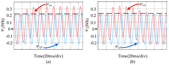
Figure 7.
Simulation results of estimated stator fluxes under the 9 V dc offset: (a) The SMFO, (b) The STSMFO.
5.2. Experimental Results
Experiments on a 2-level IPMSM drive system [32] were subsequently carried out to further verify the effectiveness of the proposed observer. The composition of the IPMSM test platform is given in Figure 8, where a DSP TMS320F2812 was chosen as the MCU and output signals of a D/A chip (TLV5610) were displayed by an oscilloscope to monitor system variables in real-time. The three-phase PWM inverter [33] is composed of IGBTs (FF650R17IE4) and a 540V dc-link voltage was obtained by the PWM rectifier. The sampling and switching periods were set to 100 μs. The sensors of current (CHB-500SG) and voltage (LV25-P) were utilized to measure ab-phase currents and dc-link voltage. The actual rotor position was detected by a rotary decoder (PGA411-Q1) for comparison. The main parameters of the IPMSM were the same as those utilized in the simulation. Moreover, the parameters of the PI regulator in phase locked loop (PLL) were and . In addition, the parameters of the STSMFO were and .
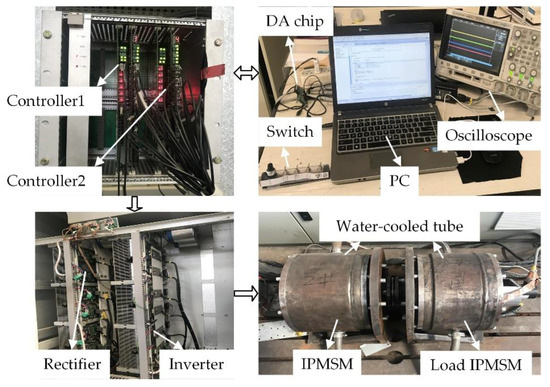
Figure 8.
The IPMSM experimental platform.
5.2.1. Steady-State Performance
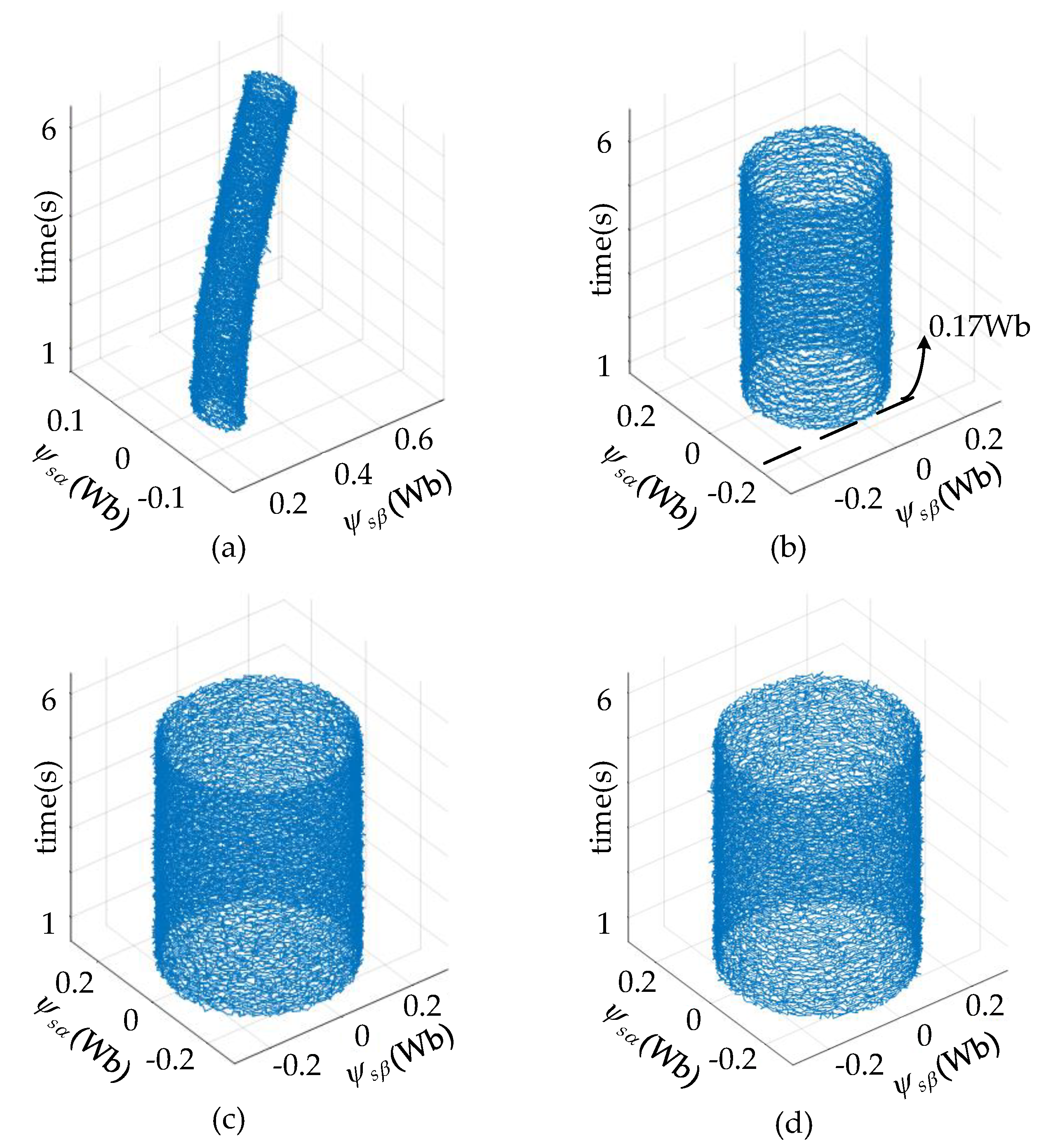
Figure 9 and Figure 10 show the estimated stator flux trajectories and rotor positions at 300 rpm, respectively. The result in Figure 9a confirms that the pure integrator will introduce a monotonously increasing dc offset in the flux estimation with respect to time. It can really deteriorate the performance of the observer, resulting in the pure integrator not being able to estimate the correct position at all. The error of estimation is approximately equal to 300 rpm. The dc offset can be removed by the LPF, but the amplitude is attenuated from the flux amplitude reference which is 0.225 Wb to 0.17 Wb. Moreover, the LPF also generates a phase delay and causes a position error of about 30°. Although both the SMFO and the STSMFO can estimate the stator flux accurately, the SMFO cannot remove the dc offset totally and results in a larger position error than the STSMFO.

Figure 9.
The estimated stator flux loci at 300 rpm: (a) Integrator, (b) LPF, (c) The SMFO, (d) The STSMFO.
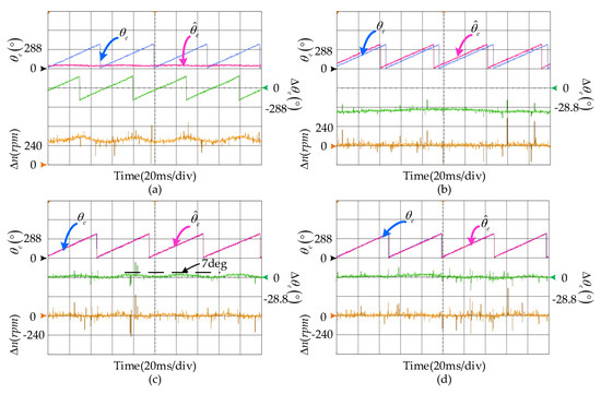
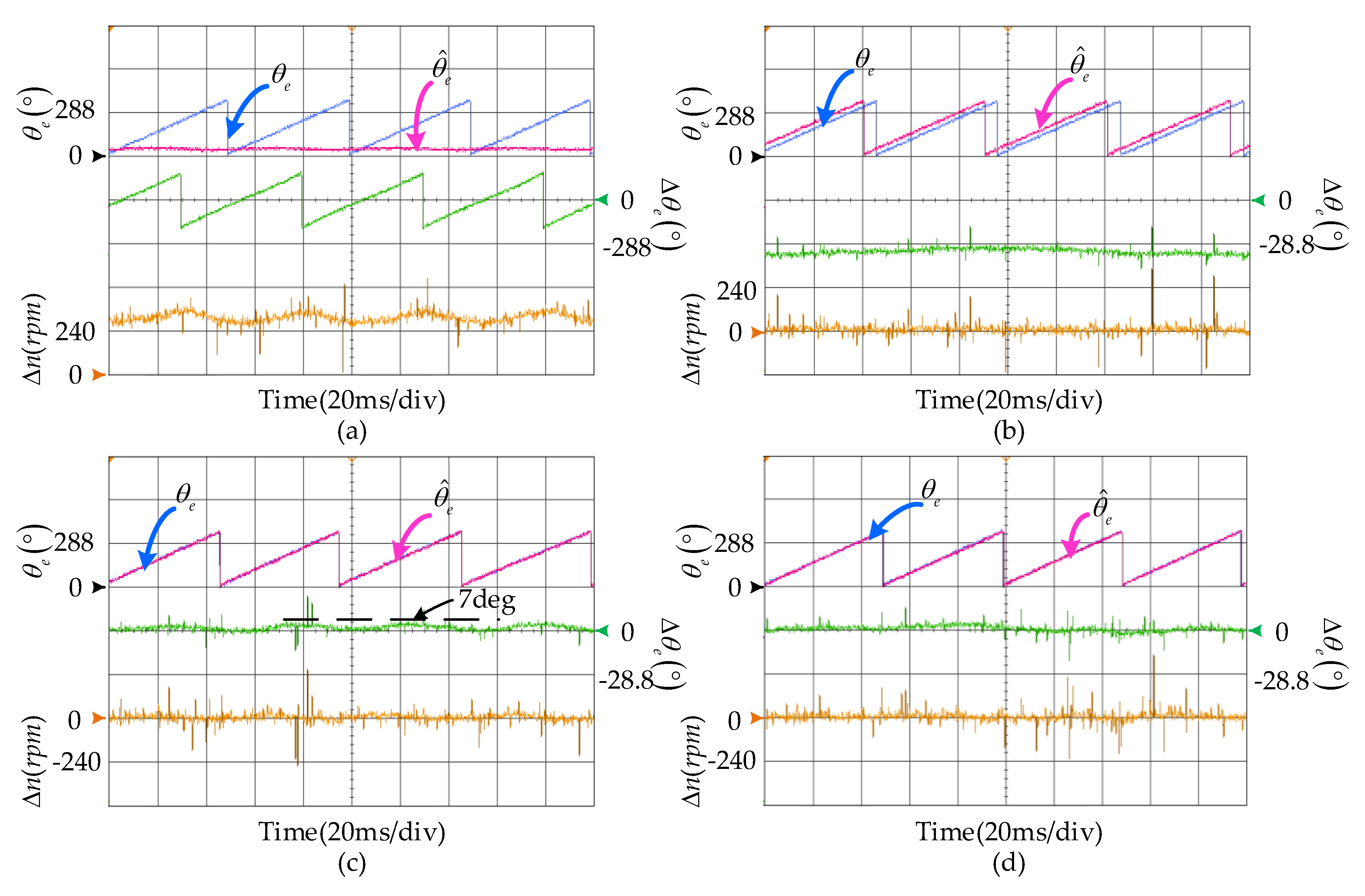
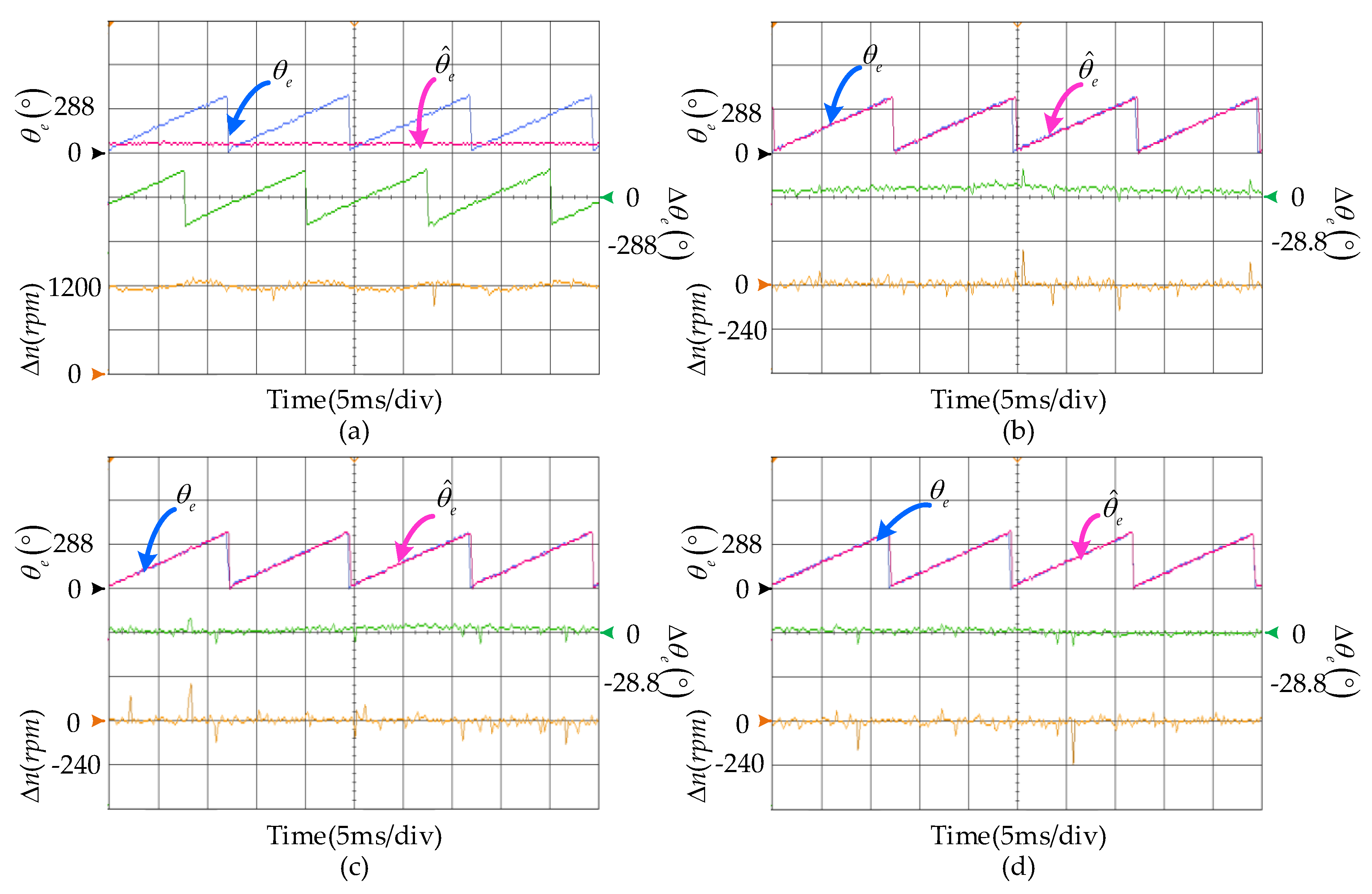
Figure 10.
The performance of the position observation at 300 rpm: (a) Integrator, (b) LPF, (c) The SMFO, (d) The STSMFO.
Besides, Figure 11 and Figure 12 plot the estimated stator flux trajectories and rotor positions at 1200 rpm. As same as the situation at 300 rpm, the pure integrator cannot observe the flux correctly and the flux locus still deviates from the ideal locus. As described in Equation (15), the problems of amplitude attenuate, and phase delay caused by the LPF are improved with the increasing speed. Compared with the performance at 300 rpm, the amplitude of the estimated flux increases from 0.175 Wb to 0.205 Wb and the position error decreases to 10°. However, the LPF still cannot meet the requirements of a high-performance sensorless control. The performance of the SMFO and the STSMFO are similar to the situation at 300 rpm. They can estimate the stator flux accurately. Moreover, the position error caused by the STSMFO is still a bit lower than the SMFO.
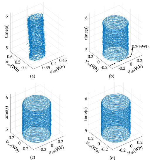
Figure 11.
The estimated stator flux loci at 1200 rpm: (a) Integrator, (b) LPF, (c) The SMFO, (d) The STSMFO.
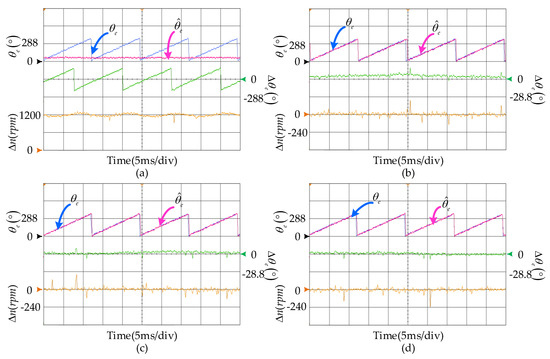
Figure 12.
The performance of the position observation at 1200 rpm: (a) Integrator, (b) LPF, (c) The SMFO, (d) The STSMFO.
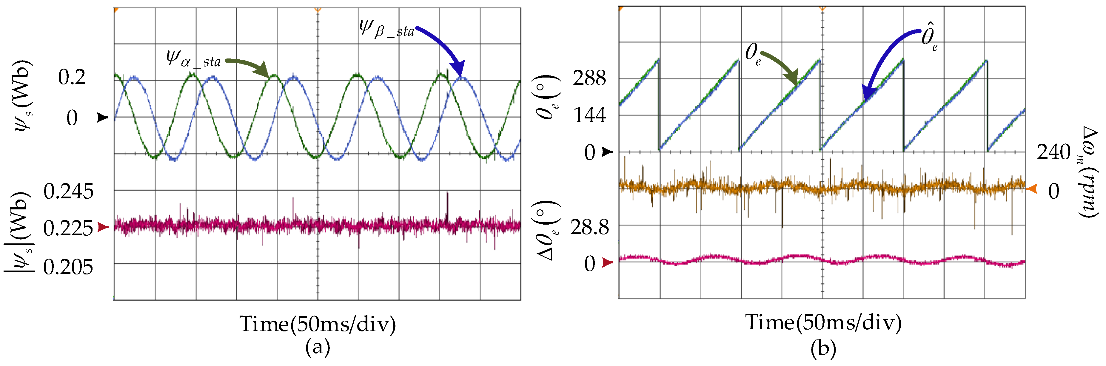
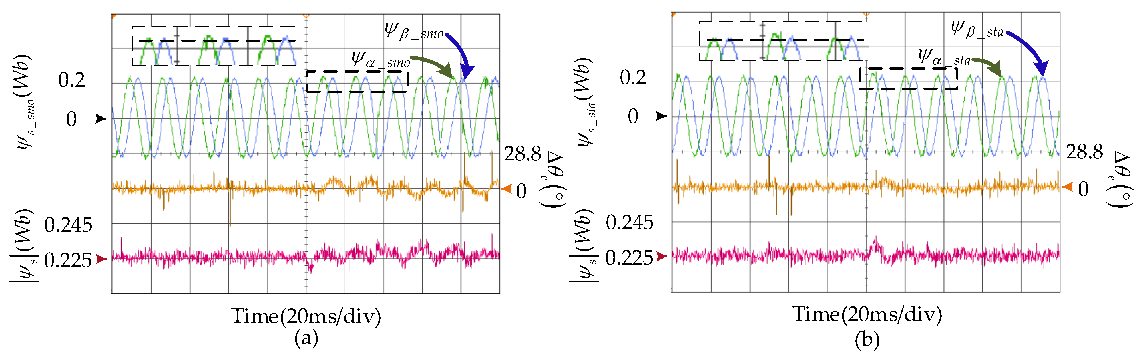
The experimental results of sensorless control which is based on the STSMFO at the 150 rpm are presented in Figure 13. The stator flux and its amplitude are given in Figure 13a. Figure 13b plots the actual and estimated position, estimated speed, and position error. As can be seen in the figure, the stator flux can be observed accurately and the chattering is small. Moreover, the figure shows a good position tracking ability of the STSMFO with a position error being controlled within 7°. Therefore, the STSMFO can be carried out at a low speed region.
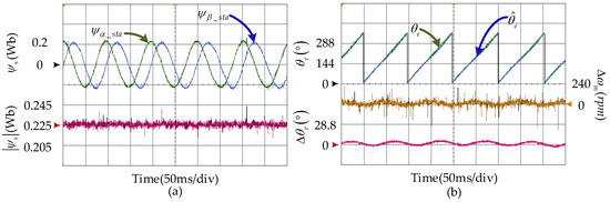
Figure 13.
The sensorless drive by the STSMFO at 150 rpm: (a) The stator flux estimation, (b) The rotor position estimation.
5.2.2. DC Disturbance Rejection
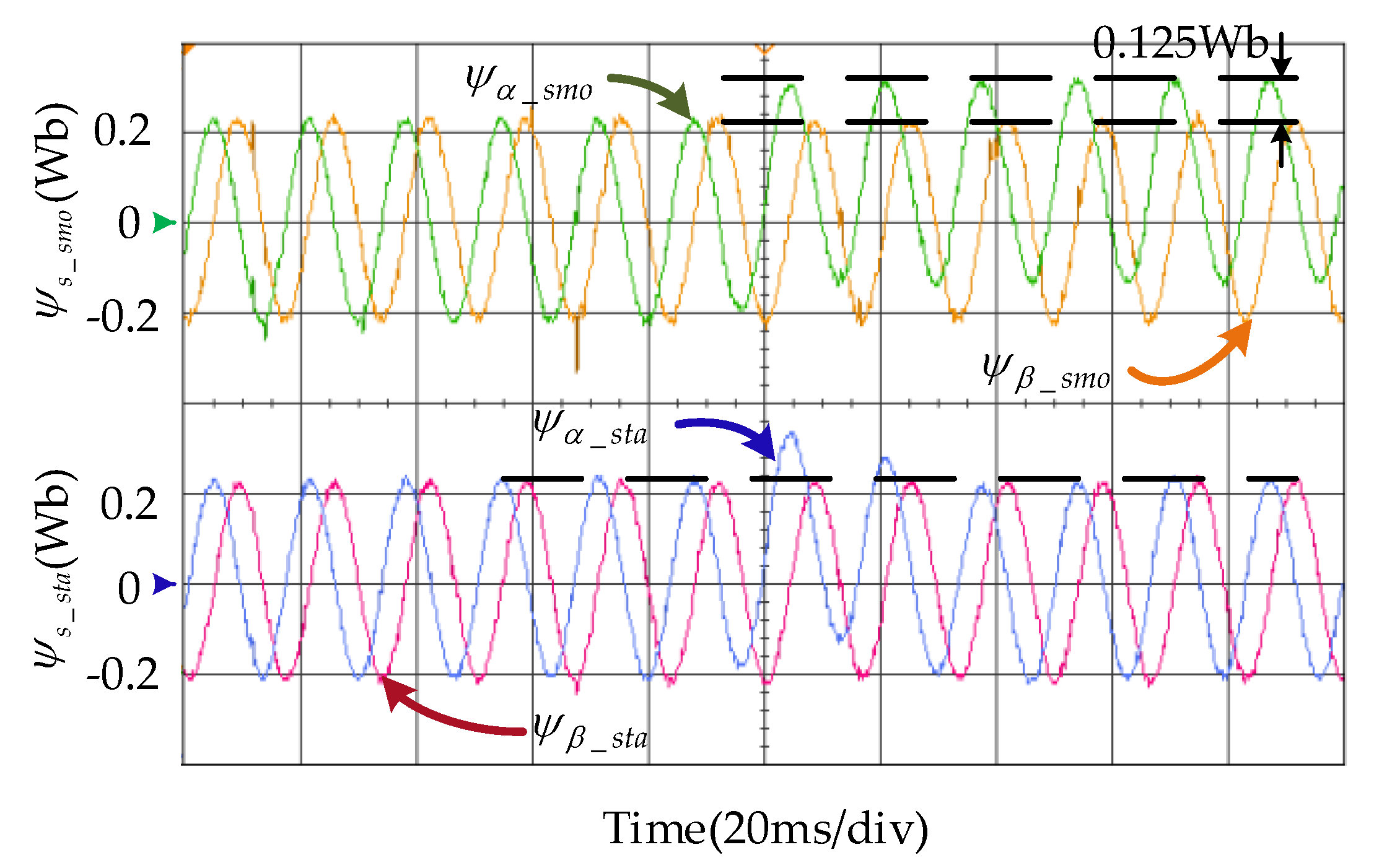
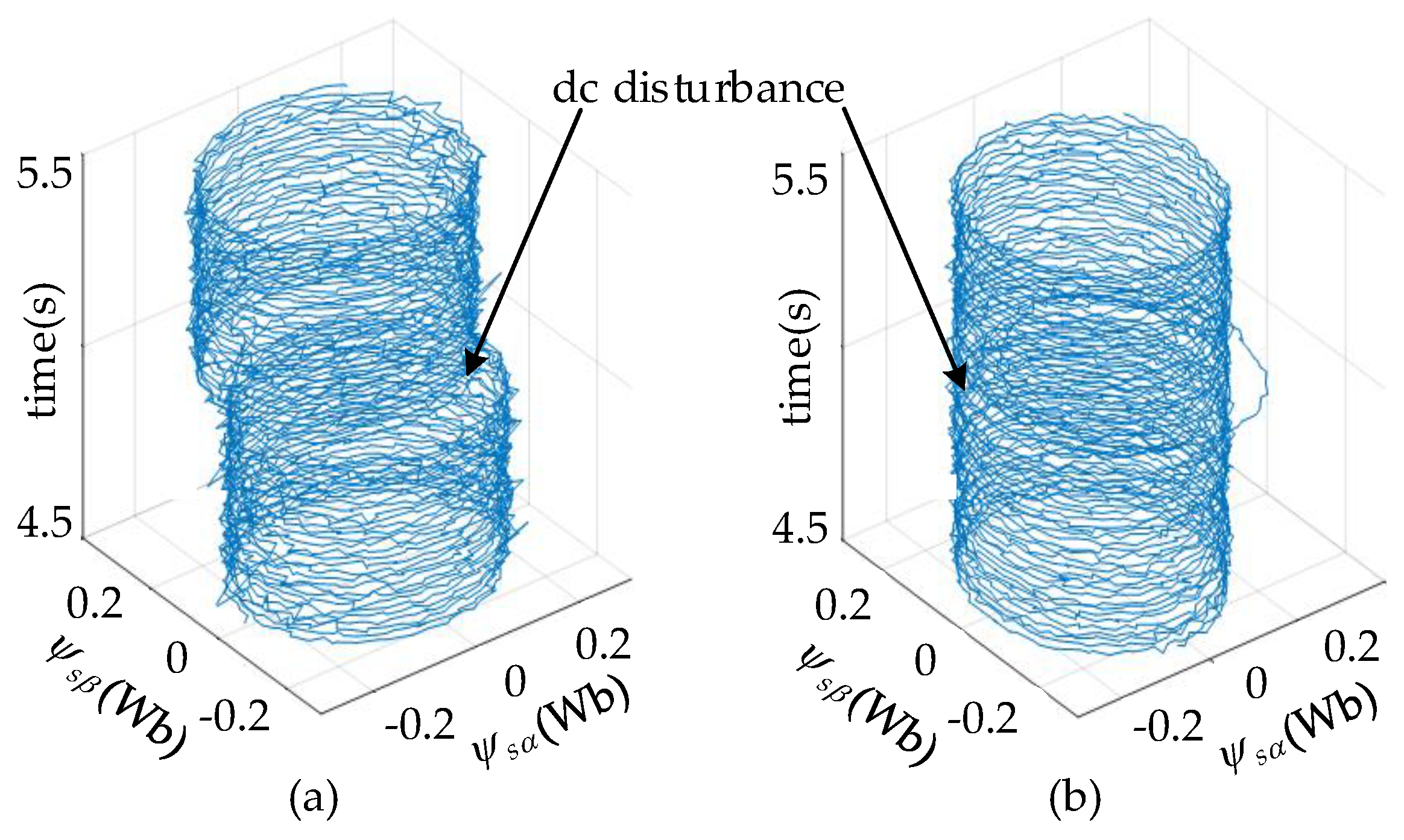
To evaluate the dc disturbance rejection capability of the STSMFO, experiments with added dc disturbance signals are also implemented and the results are illustrated in Figure 14 and Figure 15. The 20 V dc offset is added to the usα and the estimated fluxes by two observers are presented in the figure. As can be seen, there is a 0.125 Wb flux dc offset on the estimated stator flux by the SMFO since it cannot totally eliminate the dc disturbance. The flux observed by the STSMFO is also subject to dc offset, but it can recover to normal value within two sample times. The corresponding three-dimensional trajectories in Figure 14 illustrate this more intuitively.
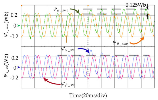
Figure 14.
The experimental results of estimated stator fluxes under the 20 V dc offset.
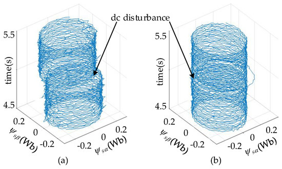
Figure 15.
Three-dimensional stator flux trajectories under dc disturbance: (a) The SMFO, (b) The STSMFO.
The sensorless drive results under the 20V dc offset are illustrated in Figure 16. The picture plots the position error, the stator flux, and its amplitude. Compared with the open loop estimation, the estimated flux dc offset of the closed-loop estimation is smaller due to the flux regulation of the DTFC. However, a small flux dc offset can still cause large chattering in the speed and it can deteriorate the performance of the sensorless control. As for the STSMFO, the flux dc offset can be eliminated within one sample time and the chattering problem of the estimated rotor position can also be solved accordingly. As can be seen, the STSMFO has stronger disturbance rejection performance than the SMFO.
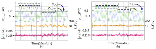
Figure 16.
The sensorless drive results under the 20 V dc offset. (a) The SMFO, (b) The STSMFO.
5.2.3. Dynamic Capability
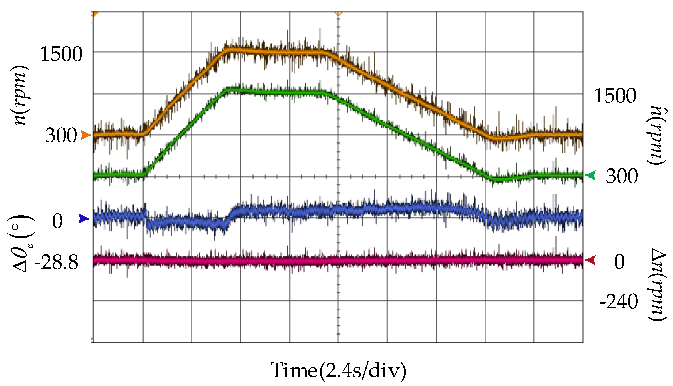
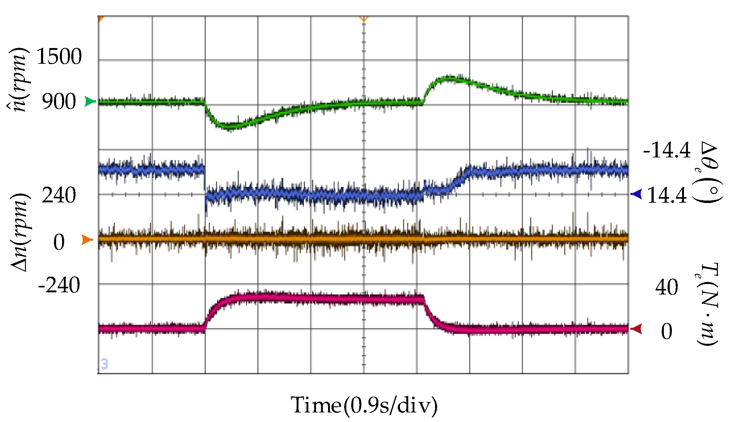
To further verify the performance of the STSMFO, the result of speed variation between 300 rpm and 1,500 rpm is given in Figure 17, which shows that the observer can accurately estimate the speed during the variable speed and control position error within 8°. Figure 18 plots the experimental result of the proposed sensorless method at 900 rpm under a 30 N·m load disturbance. The estimated speed, estimated position error, estimated speed error, and load torque are all shown in the figure. The results indicate a good speed tracking ability of the STSMFO under a load step, with a rotor position error being about 14.4°.
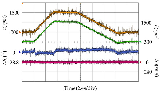
Figure 17.
The STSMFO-based sensorless drive during variable speed operation.
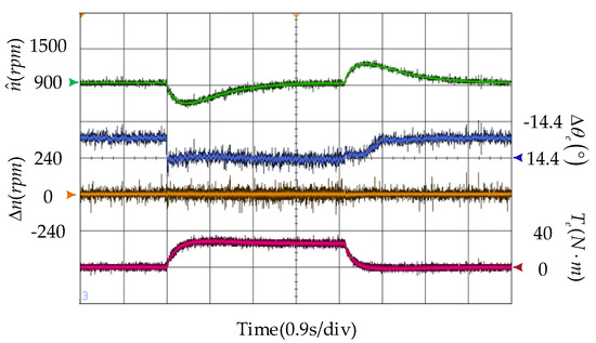
Figure 18.
The STSMFO-based sensorless drive with 30 N·m load step at 900 rpm.
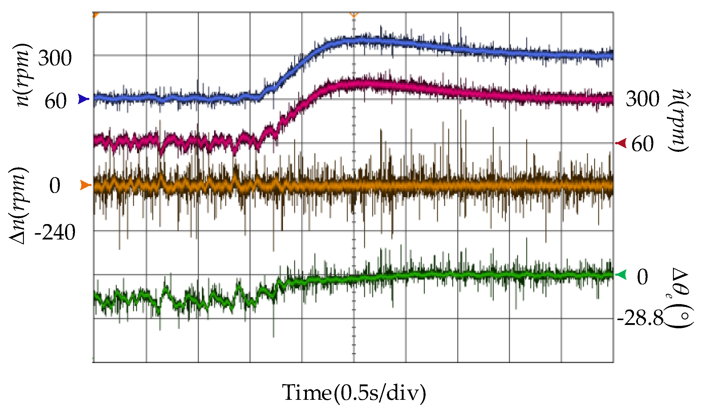
To validate the capability of the STSMFO at low speeds, the experimental result of sensorless drive during speed variation form 60 rpm to 300 rpm is presented in Figure 19. The actual and estimated speed, speed, and position estimation error are presented in the figure. It shows that the estimated rotor position error chatters a little around 14° at 60 rpm, but the speed estimation maintains a relatively high tracking accuracy over the whole speed domain, thus ensuring a stable motor operation.
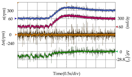
Figure 19.
The STASFO-based sensorless drive results at a low-speed region.
6. Conclusions
This paper proposed a novel STSMFO for the active flux-based sensorless scheme. To demonstrate its effectiveness, a detailed mathematical analysis was given for comparing it with traditional observers, i.e., the pure integrator, the LPF, and the SMFO. It shows that the STSMFO can easily solve the problems caused by dc offset, unknown integral initial value, and saturation. Moreover, the robustness of STSMFO is much better than SMFO. Then, the precision of the stator flux estimation can be enhanced greatly without any amplitude and phase compensation. Furthermore, the rotor position can be observed accurately via the active flux over a wide speed domain. The numerical simulations and experimental tests have confirmed the capability of the steady state, the dynamic response, and the disturbance rejection.
Author Contributions
J.C. proposed the new scheme. J.C., S.C., and X.W. performed the simulations, experiments, and data analysis. J.C. wrote the first draft and S.C., X.W., G.T., and J.H. guided and revised the manuscript.
Funding
The project is supported by the National Natural Science Foundational of China (Grant number: U1610113) and National Key R&D Program of China (Grant number: 2016YFC0600804).
Conflicts of Interest
The authors declare no conflict of interest.
References
- Li, J.; Huang, X.; Niu, F.; You, C.; Wu, L.; Fang, Y. Prediction Error Analysis of Finite-Control-Set Model Predictive Current Control for IPMSMs. Energies 2018, 11, 2051. [Google Scholar] [CrossRef]
- Lara, J.; Xu, J.; Chandra, A. Effects of Rotor Position Error in the Performance of Field Oriented Controlled PMSM Drives for Electric Vehicle Traction Applications. IEEE Trans. Ind. Electron. 2016, 63, 4738–4751. [Google Scholar] [CrossRef]
- Rahman, M.M.; Uddin, M.N. Third Harmonic Injection Based Nonlinear Control of IPMSM Drive for Wide Speed Range Operation. IEEE Trans. Ind. Appl. 2014, 55, 3174–3184. [Google Scholar] [CrossRef]
- Takahashi, I.; Noguchi, T. A New Quick-Response and High-Efficiency Control Strategy of an Induction Motor. IEEE Trans. Ind. Appl. 1986, 22, 820–827. [Google Scholar] [CrossRef]
- Ouanjli, N.E.; Derouich, A.; Ghzizal, A.E.; Motahhir, S.; Chebabhi, A.; Mourabit, Y.E.; Taoussi, M. Modern improvement techniques of direct torque control for induction motor drives—A review. Prot. Control Mod. Power Syst. 2019, 4, 136–147. [Google Scholar] [CrossRef]
- Choi, Y.; Choi, H.H.; Jung, J. Feedback Linearization Direct Torque Control with Reduced Torque and Flux Ripples for IPMSM Drives. IEEE Trans. Power Electron. 2016, 31, 3728–3737. [Google Scholar] [CrossRef]
- Tang, L.; Zhong, L.; Rahman, M.F.; Hu, Y. A Novel Direct Torque Controlled Interior Permanent Magnet Synchronous Machine Drive with Low Ripple in Flux and Torque and Fixed Switching Frequency. IEEE Trans. Power Electron. 2004, 19, 346–354. [Google Scholar] [CrossRef]
- Foo, G.; Rahman, M.F. Sensorless Direct Torque and Flux-Controlled IPM Synchronous Motor Drive at Very Low Speed Without Signal Injection. IEEE Trans. Ind. Electron. 2010, 57, 395–403. [Google Scholar] [CrossRef]
- Chen, J.; Yang, S.; Tu, J. Comparative Evaluation of a Permanent Magnet Machine Saliency-Based Drive with Sine-Wave and Square-Wave Voltage Injection. Energies 2018, 11, 2189. [Google Scholar] [CrossRef]
- Yousefi-Talouki, A.; Pescetto, P.; Pellegrino, G.; Boldea, I. Combined Active Flux and High Frequency Injection Methods for Sensorless Direct Flux Vector Control of Synchronous Reluctance Machines. IEEE Trans. Power Electron. 2018, 33, 2447–2457. [Google Scholar] [CrossRef]
- Yoon, Y.; Sul, S.; Morimoto, S.; Ide, K. High-Bandwidth Sensorless Algorithm for AC Machines Based on Square-Wave-Type Voltage Injection. IEEE Trans. Ind. Appl. 2011, 47, 1361–1370. [Google Scholar] [CrossRef]
- Shi, Y. Online Identification of Permanent Magnet Flux Based on Extended Kalman Filter for IPMSM Drive with Position Sensorless Control. IEEE Trans. Ind. Electron. 2012, 59, 4169–4178. [Google Scholar] [CrossRef]
- Chen, S.; Zhang, X.; Wu, X.; Tan, G.; Chen, X. Sensorless Control for IPMSM Based on Adaptive Super-Twisting Sliding-Mode Observer and Improved Phase-Locked Loop. Energies 2019, 12, 1225. [Google Scholar] [CrossRef]
- Vieira, R.P.; Gastaldini, C.C.; Azzolin, R.Z.; Gründling, H.A. Sensorless Sliding-Mode Rotor Speed Observer of Induction Machines Based on Magnetizing Current Estimation. IEEE Trans. Ind. Electron. 2014, 61, 4573–4582. [Google Scholar] [CrossRef]
- Fan, Y.; Zhang, L.; Cheng, M.; Chau, K.T. Sensorless SVPWM-FADTC of a New Flux-Modulated Permanent-Magnet Wheel Motor Based on a Wide-Speed Sliding Mode Observer. IEEE Trans. Ind. Electron. 2015, 62, 3143–3151. [Google Scholar] [CrossRef]
- Gadoue, S.M.; Giaouris, D.; Finch, J.W. MRAS Sensorless Vector Control of an Induction Motor Using New Sliding-Mode and Fuzzy-Logic Adaptation Mechanisms. IEEE Trans. Energy Convers. 2010, 25, 394–402. [Google Scholar] [CrossRef]
- Boldea, I.; Paicu, M.C.; Andreescu, G. Active Flux Concept for Motion-Sensorless Unified AC Drives. IEEE Trans. Power Electron. 2008, 23, 2612–2618. [Google Scholar] [CrossRef]
- Boldea, I.; Paicu, M.C.; Andreescu, G.; Blaabjerg, F. “Active Flux” DTFC-SVM Sensorless Control of IPMSM. IEEE Trans. Energy Convers. 2009, 24, 314–322. [Google Scholar] [CrossRef]
- Zhao, R.; Xin, Z.; Loh, P.C.; Blaabjerg, F. A Novel Flux Estimator Based on Multiple Second-Order Generalized Integrators and Frequency-Locked Loop for Induction Motor Drives. IEEE Trans. Power Electron. 2017, 32, 6286–6296. [Google Scholar] [CrossRef]
- Xu, W.; Jiang, Y.; Mu, C.; Blaabjerg, F. Improved Nonlinear Flux Observer-Based Second-Order SOIFO for PMSM Sensorless Control. IEEE Trans. Power Electron. 2019, 34, 565–579. [Google Scholar] [CrossRef]
- Choi, J.; Nam, K.; Bobtsov, A.A.; Pyrkin, A.; Ortega, R. Robust Adaptive Sensorless Control for Permanent-Magnet Synchronous Motors. IEEE Trans. Power Electron. 2017, 32, 3989–3997. [Google Scholar] [CrossRef]
- Lin, T.C.; Zhu, Z.Q.; Liu, J.M. Improved Rotor Position Estimation in Sensorless-Controlled Permanent-Magnet Synchronous Machines Having Asymmetric-EMF with Harmonic Compensation. IEEE Trans. Ind. Electron. 2015, 62, 6131–6139. [Google Scholar] [CrossRef]
- Roberto, M.; Edmundo, B.; Marco, A.A.; Hernández, C. Sensorless Predictive DTC of a Surface-Mounted Permanent-Magnet Synchronous Machine Based on Its Magnetic Anisotrogy. IEEE Trans. Ind. Electron. 2013, 60, 3016–3024. [Google Scholar]
- Levant, A. Sliding order and sliding accuracy in sliding mode control. Int. J. Control 1993, 58, 1247–1263. [Google Scholar] [CrossRef]
- Liang, D.; Li, J.; Qu, R. Sensorless Control of Permanent Magnet Synchronous Machine Based on Second-Order Sliding-Mode Observer with Online Resistance Estimation. IEEE Trans. Ind. Appl. 2017, 53, 3672–3682. [Google Scholar] [CrossRef]
- Liang, D.; Li, J.; Qu, R.; Kong, W. Adaptive Second-Order Sliding-Mode Observer for PMSM Sensorless Control Considering VSI Nonlinearity. IEEE Trans. Power Electron. 2018, 33, 8994–9004. [Google Scholar] [CrossRef]
- Li, Z.; Zhou, S.; Xiao, Y.; Wang, L. Sensorless Vector Control of Permanent Magnet Synchronous Linear Motor Based on Self-adaptive Super-twisting Sliding Mode Controller. IEEE Access 2019, 7, 44998–45011. [Google Scholar] [CrossRef]
- Holakooie, M.H.; Ojaghi, M.; Taheri, A. Modified DTC of a Six-Phase Induction Motor with a Second-Order Sliding-Mode MRAS-Based Speed Estimator. IEEE Trans. Power Electron. 2019, 34, 600–611. [Google Scholar] [CrossRef]
- Moreno, J.A.; Osorio, M. A Lyapunov approach to second-order sliding mode controlers and observer. In Proceedings of the 47th IEEE Conference on Decision and Control, Cancun, Mexico, 9–11 December 2008; pp. 2856–2861. [Google Scholar]
- Moreno, J.A.; Osorio, M. Strict Lyapunov Functions for the Super-Twisting Algorithm. IEEE Trans. Autom. Control 2012, 57, 1035–1040. [Google Scholar] [CrossRef]
- Zhong, L.; Rahman, M.F.; Hu, W.; Lim, K.W. Analysis of Direct Torque Control in Permanent Magnet Synchronous Motor Drives. IEEE Trans. Power Electron. 1997, 12, 528–536. [Google Scholar] [CrossRef]
- Wu, X.; Tan, G.; Ye, Z.; Liu, Y.; Xu, S. Optimized Common-Mode Voltage Reduction PWM for Three-Phase Voltage Source Inverters. IEEE Trans. Power Electron. 2016, 31, 2959–2969. [Google Scholar] [CrossRef]
- Xia, Y.; Gou, B.; Xu, Y. Anew ensemble-based classifier for IGBT open-circuit fault diagnosis in three-phase PWM converter. Prot. Control Mod. Power Syst. 2018, 3, 364–372. [Google Scholar] [CrossRef]


© 2019 by the authors. Licensee MDPI, Basel, Switzerland. This article is an open access article distributed under the terms and conditions of the Creative Commons Attribution (CC BY) license (http://creativecommons.org/licenses/by/4.0/).