Abstract
This paper develops a neural network (NN) vector controller for an interior mounted permanent magnet (IPM) motor by using a Texas Instrument TMS320F28335 digital signal processor (DSP). The NN controller is developed based on the complete state-space equation of an IPM motor and it is trained to achieve optimal control according to approximate dynamic programming (ADP). A DSP-based NN control system is built for an IPM motor drives system, and a high efficient DSP program is developed to implement the NN control algorithm while considering the limited memory and computing capability of the TMS320F28335 DSP. The DSP-based NN controller is able to manage IPM motor control in linear, over, and six-step modulation regions to improve the efficiency of IPM drives and to allow for the full utilization of DC bus voltage with space-vector pulse-width modulation (SVPWM). The experiment results show that the proposed NN controller is able to operate with a sampling period of 0.1ms, even with limited DSP resources of up to 150 MHz cycle time, which is applicable in practical motor industrial implementations. The NN controller has demonstrated a better current and speed tracking performance than the conventional standard vector controller for IPM operation in both the linear and over-modulation regions.
1. Introduction
Stringent emission laws and regulations and increased demand for fuel-efficient, high-performance vehicles are compelling the automobile manufacturers worldwide to equip their vehicles with alternative fuel technologies, which results in increased overall market adoption of electric vehicles (EVs). The global EV market was valued at $103,342 million in 2016 and it is projected to reach $350,963 million by 2023, growing at a compound annual growth rate (CAGR) of 19.8% from 2017 to 2023 [1]. The key EV manufacturers, such as Toyota Motor Corp., Volkswagen AG, and Tesla, expanded their business by globally opening various research and manufacturing facilities. In addition, they have launched more efficient and advanced EVs to enhance their market share.
However the high performance and efficiency of EV electric and electronic components are critical in the growth of the EV market due to the limited space within an EV. An electric motor is one of the most important EV components. An EV uses one or more electric motors for propulsion. The most widely used electric motor in the automobile industry is permanent magnet synchronous motors (PMSM). There are two main types of permanent magnet (PM) motors: surface mounted PM (SPM) motor and interior mounted PM (IPM) motor [2]. For an SPM motor, the magnets of the motor are on the surface of the rotor. For an IPM motor, the magnets are buried inside the rotor. IPM motors, which are suitable for operation at both low and high speeds, are the primary motors used by the EV industry due to the requirement for operation over a wide speed range [3]. Significant R&D investment has been made by the automobile companies to improve IPM motor performance, efficiency, and reliability to meet EV operation requirements on broad, varied conditions. Similar research activities are also ongoing on more advanced applications in the electric drone industry [4].
Improving the performance, efficiency, and reliability of IPM motors requires (1) minimizing energy loss, (2) maximizing voltage utilization especially for a driving torque demand at high speed, and (3) implementing advanced control technology. From the energy loss perspective, at each EV operating condition, an efficient reference command needs to be generated for the control of an IPM motor. Space vector pulse width modulation (SVPWM) is usually used from the voltage utilization standpoint, instead of the traditional sinusoidal pulse width (SPWM) modulation scheme, for controlling an IPM motor through power inverters [5]. Further improvement of the efficiency requires SVPWM to be extended from the traditional linear modulation region to the over-modulation regions [6].
Various advanced control techniques for IPM motor drives have been recently developed [7,8,9,10,11]. Sliding-mode control (SMC) is a popular method that has been developed in recent years for IPM motor control. The SMC may produce a large switching gain, which may cause the undesired chattering, although it is less sensitive to parameter uncertainties and external disturbance [7,9]. Meanwhile, the SMC cannot keep the property of invariance in the presence of unmatched uncertainties. As a result, disturbance observers were proposed to improve the performance of SMC-based IPM motors [7]. However, the accuracy of the disturbance observers is critical in the SMC-based IPM performance and it strongly depends on the motor parameters, which could affect the SMC-based control, as motor parameters broadly change in practical operating conditions. A few research articles also show the use of model predictive control (MPC) for the control of IPM motors [10,11]. However, a weakness of the MPC is that it would become unstable when the model parameters differ from the actual values.
A novel neural network (NN) vector control technology that is based upon approximate dynamic programming (ADP) has been developed to improve the performance, stability, and adaptivity of the IPM motor in recent years [12]. However, due to the complexity of an NN, some major concerns from professionals in this field are: how an NN controller for an IPM motor can be implemented while using regular digital signal processor (DSP) chips that have limited memory and computing capability; what the detailed hardware configuration should be for the NN controller; how to implement the DSP-based NN control algorithm; and, how the DSP-based NN controller behaves in hardware experimental conditions when compared to existing methods.
This paper is the first to address the development and implementation of ADP-NN based control while using a low cost embedded microcontroller. The specific contributions of this paper include (1) a special NN design with inputs containing errors and integrals of errors, making the NN have the conventional proportional-integral (PI) control characteristics, (2) an NN controller that is developed based on the complete IPM motor state-space equation, which makes the control actions that are generated by the NN controller better and more accurately meet the IPM motor drives requirements, (3) an ADP-based training of the NN that allows for the NN controller to gain the optimal control characteristics over a long time horizon, (4) an implementation of NN vector control technology while using Texas Instruments (TI) TMS320F28335 DSP chip, (5) mechanisms and strategies that can help in improving the computing speed of the NN controller on the DPS chip, and (6) test and comparison of the NN controlled IPM motor performance with the conventional controlled one in both the linear and over-modulation regions of SVPWM.
The rest of the paper is structured as follows: Section 2 presents the conventional standard PI and proposed NN control structures for an IPM motor as well as the SVPWM in the linear and over-modulation regions. Section 3 shows the strategy of how to tune the PI controller and how to train an NN controller for an IPM motor to achieve ADP-based optimal and predictive control. Section 4 gives the hardware structure of a DSP-based control system, as developed in this paper, while using PI and NN techniques that are based on TI TMS320F28335. Section 5 explains the DSP software implementation of the PI and NN vector control as well as the methods to enhance the computing efficiency of the NN controller over the DSP chip. Section 6 investigates and compares the performance of the conventional PI and NN-based DSP control algorithms by hardware tests. Finally, the paper gives a conclusion of the main points.
2. Neural Network and Conventional Standard Control Structures
2.1. Control for IPM Motor Drives
An IPM is commonly controlled based on the well-known vector control technology, like other ac electric machines. A typical conventional field-oriented vector controller for an IPM motor has two decoupled d- and q-axis current controllers to fulfill the magnetic field and torque control of the motor, respectively. A reference torque is first generated according to the driving requirement of the EV or electric drone under different road or flying conditions, in a practical application, such as an EV or electric drone. Subsequently, the torque reference is converted into d- and q-axis current references. The torque of an IPM motor is related to the stator current of the motor by
where p is pole pairs, id and iq are the d- and q-axis components of the instant stator current, Ld and Lq are the stator d- and q-axis inductances, and ψf is the flux linkage that is produced by the permanent magnet.
According to (1), for a given torque reference τ*em, there are multiple current vectors that can generate the specified torque. The current vector, which has minimum magnitude, is called the maximum torque per ampere (MTPA) current and it represents the operating condition of the minimum copper loss for the commanded torque [13,14]. Conventionally (Figure 1), the flux-weakening and MTPA block generates optimal d- and q-axis reference currents, which are based on the motor parameters (Ld, Lq, and ψpm), motor speed, and a desired torque command τ*em that is needed for driving an EV or electric drone. The current controller block tracks the reference currents that are generated by the flux weakening and MTPA block or tracks the reference currents as much as possible if reaching the physical constraint limitations, in terms of the rated current and PWM saturation limits, of the IPM motor drives system.
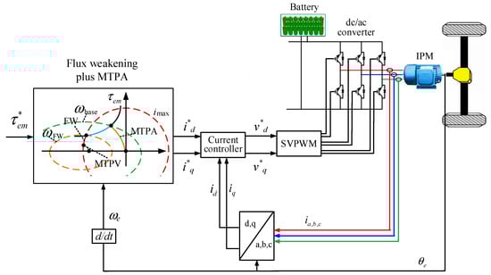
Figure 1.
Typical interior mounted permanent magnet (IPM) motor drive and control structure.
2.2. Conventional Standard Control Structure
The d- and q-axis current control of an IPM motor is conventionally implemented through a decoupled control structure, as shown in Figure 2, in which the reference stator d- and q-axis currents, i*d and i*q, are generated by the MTPA and the flux weakening block, and id and iq are the actually measured stator d- and q-axis currents. For each of the d- and q-axis control loop, the error signal between the reference and actual stator currents passes through a PI controller, which is normally followed by added compensation terms, to formulate the d- or q-axis control voltage for the IPM motor. The resultant d- and q-axis control voltage is normalized over the peak six-step fundamental voltage and is then applied to the IPM motor through the SVPWM of the IPM converter.
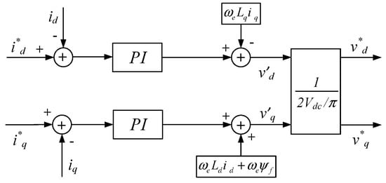
Figure 2.
Structure of conventional standard controller.
2.3. Neural Network Control Structure
Figure 3 shows the NN control structure for the d- and q-axis current control of an IPM motor. The NN, which is also called the action network, is a multilayer neural network that consists of four different layers: an input layer, two hidden layers, and an output layer (Figure 3). The input layer contains four inputs. Two of these inputs comprise the error terms between the reference and actual stator d- and q-axis currents, and the other two comprise the integral of the error terms. This special input structure to the NN would allow for the NN to gain the conventional PI control characteristics. These four input terms are defined by
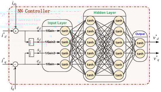
Figure 3.
Structure of the neural network (NN) controller.
The output layer gives which is applied to the IPM motor through the SVPWM of the IPM converter. Therefore, the actual control action applied to the IPM motor that is contributed by the NN controller equals multiplied by a gain, kPWM, caused by the SVPWM of the IPM converter [15]. Consequently, the final control action applied to the IPM motor, , is given by
where is the neural network’s overall weight vector and denotes the whole action neural network.
2.4. Control of IPM Motor in Linear to Over-Modulation Regions
Over-modulation operation is needed to extend the maximum voltage that can be generated by the controller and applied to the IPM inverter in order to fully utilize DC bus voltage for achieving maximum output torque of an IPM motor. Over-modulation aims to extend the linear modulation region of the SVPWM, which leads to the better utilization of the DC bus voltage and enhances the MTPA range of an IPM motor.
For a general SPWM, the highest possible fundamental peak phase voltage is 0.5Vdc (Figure 4). With the SVPWM, the fundamental peak phase voltage can be as high as in linear modulation mode when the reference control voltage vector makes the inner circular trajectory, as shown in Figure 4. The linear or over-modulation operation for the SVPWM is determined by the modulation index as:
where V* is the peak phase voltage generated from the controller and Vdc is the DC bus voltage of the inverter. Figure 4 shows the linear and over-modulation regions.
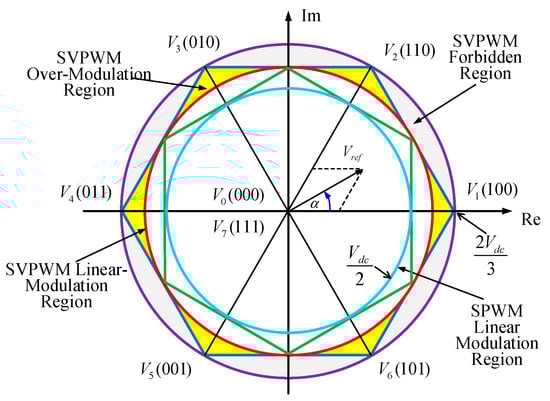
Figure 4.
Linear and Over-modulation Regions in Space Vector Representation.
When MI is below 0.906, the SVPWM works in linear modulation range and the inverter can provide full control ability. When MI is from 0.906 up to 1, the SVPWM works in the over-modulation region, which is usually divided into over-modulation regions I and II, depending on MI [6]. In over-modulation region I, where MI ranges from 0.906 to 0.952, the actual voltage vector keeps the same phase angle of the control voltage vector as in linear modulation region, but its amplitude varies over time, in which the inverter can only provide partial control ability. In over-modulation region II, corresponding to MI ranging from 0.952 up to 1, both the amplitude and angle of the control voltage vector are modified [6,16,17], in which the inverter can just provide even more limited partial control ability when compared to over-modulation region I. When MI reaches 1, the control voltage generated from the controller needs to be saturated, since the inverter has reached the maximum possible voltage and the inverter works on the six-step modulation [18]. Thus, the inverter can only provide the tracking of the reference d- and q-axis currents according to the six-step modulation rule in the six-step modulation region, which means that more oscillation would appear in the actual d- and q-axis currents as shown by the hardware experimental results in Section 6. The ability to be able to generate an optimal and more accurate control action is critical for IPM motor drives, especially in overnodulation mode, due to the partial control ability in over-modulation regions. An NN controller can be trained to better achieve this requirement, as explained in Section 3.
3. Determining Controller Parameters
3.1. IPM Motor Model
An IPM motor model is needed to determine the parameters of the conventional PI and the proposed NN controllers. While using the Park transformation, the state-space IPM model is [19]
where the system states are id and iq; ωe is the electrical rotational speed of the motor; Rs is the stator winding resistance; the rotor magnet flux ψf is assumed constant; and, vd and vq are the d- and q-axis components of the instant stator voltage, which is proportional to the control voltage that is generated by the controller [15,19]. In (6), Rs, Ld, Lq, and ψf are either specified by the manufacturer or obtained from experiment measurement. However, it is important that those parameters should be estimated accurately in the real-time operation of an IPM motor [20] for more accurate MTPA and flux weakening implementation, which is beyond the scope of this paper.
3.2. Determing Parameters of Conventional Controller
The parameters of the conventional standard PI controller are determined based on the decoupled and simplified model of the IPM motor, which is obtained from (6), as shown below
from which the transfer functions between the output current and input control voltage of the IPM motor for the d- and q-axis loops are 1/(Rs + s·Ld) and 1/(Rs + s·Lq), respectively, which represent the plant transfer functions of the IPM motor that is used to tune the PI controllers. The frequency response method was used to tune the PI controllers in this, in which the crossover frequency was 100 Hz and the phase margin was 60°.
3.3. Determing Parameters of NN Controller
The network weights are the parameters of the neural network controller that need to be determined, which are obtained through an NN training process. Unlike the conventional standard PI controller, the NN controller is trained based on the complete state-space model of the IPM motor that is represented by (6), which would make the control actions that are generated by the NN controller more accurately meet the IPM motor drives requirements. However, the discrete equivalent of the continuous state-space model must be obtained by utilizing a zero-order or first-order hold discrete equivalent mechanism since an NN controller is a digital controller. The transformation yields
in which Ts is the sampling period, A is the system matrix, and B is the input matrix. As Ts is present on both sides, (9) can be simplified as
where k is an integer time step.
In this paper, the training objective of the NN controller is to achieve optimal control that is based on approximate dynamic programming (ADP) [21,22,23]. The ADP cost-to-go function or the objective function of the optimal control problem used in the paper is:
where N is the trajectory length. Such an ADP-based training would allow for the NN controller to gain the optimal control characteristics over a long time horizon. In this paper, each trajectory length is 1 second and the sampling period Ts is 0.1 ms. Thus, in terms of N, the length of each trajectory is 10,000. A dozen of trajectories were randomly generated to train the NN controller.
For the NN to achieve ADP-based optimal control, it is needed to minimize the cost-to-go function (11) through the training of the NN. The NN receives the d-q current feedback signals from the IPM motor, making the combined system of the IPM + NN similar to a recurrent neural network, as shown in Figure 1 and Figure 3. For training the recurrent NN, the gradient of (11) with respect to the network weight vector is calculated through the chain rule. The calculation starts from (11) and it passes through (10), the NN, and (2) and (3). The process is repeated until the calculation goes through all of the trajectory length. After that, the adjustment of network weights can be obtained and the network weights are updated as
The network weights are repeatedly adjusted until a well-trained NN is obtained. The motor parameter changes are considered as noises during the training of the network, which would give the trained NN a special advantage and strong adaptive capability. After successful training, the NN is able to implement optimal d-q current control that is based on ADP, i.e., to make the actual d-q current track the d-q reference current trajectories as closely as possible. A more detailed description regarding training the NN to achieve the ADP-based vector control is presented in [24]. The NN controller is trained for a laboratory IPM motor [25] with the parameters of the motor that are shown in Table 1. The sampling time used during both the training and real-time control stages of the NN controller is 0.1 ms. Note: the NN is trained offline, and no training occurs in the real-time control stage. Additionally, unlike a typical traction IPM motor that is used in EV applications, the maximum speed of the laboratory motor is relevant low compared to the typical speed over 10,000 rpm for an EV IPM motor [26]. In the future, we plan to train an NN controller for the EV IPM motor and test the performance of the motor under the NN control when a more practical EV IPM motor is available.

Table 1.
IPM Data Used in Experimental Study.
4. Building DSP-Based Microcontroller Hardware for IPM Motor Drives
The DSP-based microcontroller hardware setup consists of the following components: (i) an IPM motor from Motorsolver (parameters shown in Table 1) with a built-in encoder for the measurement of motor rotor positions, (ii) a TDK-Lambda GEN500-8.5 DC power supply that supplies power to the motor, (iii) a Lab-Volt 8857-10 3-phase IGBT inverter, (iv) a Texas Instrument C2000 Delfino 32-bit microcontroller board [27], which contains a TMS320F28335 floating-point DSP with 150 MHz execution frequency, and (v) a sensor board specially developed for measurement of motor currents that can fit the TMS320F28335 requirements. Figure 5 shows the schematics and circuit connection of the experiment system. Details regarding the design of the sensor board and hardware and software design of TMS320F28335 DSP with the overall system are presented below.
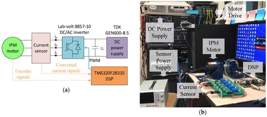
Figure 5.
Building a hardware experiment system for digital signal processor (DSP)-based microcontroller. (a) Experiment schematic; and, (b) Experiment setup.
4.1. Sensor Board Design and Development
The sensor board consists of five ac current sensors (Figure 5). For the development of an ac current sensor, it is first needed to specify the range of the current signals that are to be measured. For the three-phase IPM motor, the maximum RMS motor current per phase is less than 10 A. Therefore, a current transducer (Figure 6) having input current limit specification of 20 A RMS is selected [28]. The output voltage of the current transducer VOUT is within 0 V to +5 V range when the measured ac current ia is −20 A to +20 A [28]. Note: VSS in Figure 6 is the Ground pin, i.e., 0 V. Second, a voltage divider (R1 = 20 kΩ and R2 = 39 kΩ) is added to the output of the current transducer, since the measured signal type and range that can be applied to TMS320F28335 must be voltage signals within the range of 0–3.3V, which makes the output voltage of the current sensor within the receivable range. Third, for the sampling time of 0.1 ms used for either the conventional PI or NN controller, an antialiasing low-pass filter Rf-Cf with a 5 kHz cutoff frequency is designed and added to the output of the current sensor to substantially remove all of the spectral contents above the half sampling frequency within the measured signal, so as to restrict the bandwidth of the signal to approximately satisfy the sampling theorem over the band of interest. Figure 6 shows the complete design and circuit schematics of the current sensor for the measurement of the phase-a current. The conversion equation from the measured current to the converted voltage after being verified through hardware experiment testing is
which makes output voltage range as 0.99 V to 2.31 V for measured current from −20 A to 20 A, where VDD is +5 V and vh is the sensitivity of the current sensor (50 mv/A).
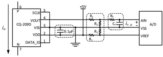
Figure 6.
Current sensor design for TMS320F28335-based NN controller.
4.2. Design of TMS320F28335 DSP with IPM Motor Drives System
Overall, the TMS320F28335-based microcontroller receives input data in terms of the measured currents and position/speed from IPM motor and sends driving pulses to control the motor through the IPM inverter, as shown in Figure 5a.
The current measurement of the IPM motor, as needed by the DSP-based microcontroller, is converted into analog voltage signal iv through the current sensor that is discussed above and then must be presented to the DSP in a digital signal format. The ADC module of TMS320F28335 [29] at each sampling interval handle this, as illustrated in Figure 7. First, the operation of the ADC module is triggered by a sampling interrupt signal, Start-of-Sequence Trigger in Figure 7, coming from either the conventional PI or the NN controller program (Section 5) at each sampling interval of 0.1 ms. The Autosequencer State Machine of the ADC module controls the MUX to start getting the voltage signal from the first input channels, sends a SOC (start of conversion) signal to the 12-bit ADC converter, and controls DMUX to save the converted digital signal to the result register after the ADC module is triggered. Subsequently, the ADC Converter sends an EOC (end of conversion) signal to the State Machine that moves its pointer to the next input channel. The process repeatedly continues until the stator current signals of all three phases are converted into corresponding digital signals, which are saved into the three result registers. After that, the digital representations of the measured three-phase currents at the corresponding sampling time interval are available for the conventional PI or NN controller to read and use.
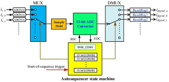
Figure 7.
Hardware structure of the data acquisition system.
When considering (13), the final conversion equation is
The mechanical speed ωm and position in terms of electrical angle ϴe of the IPM motor, which are also needed by the DSP-based microcontroller, are obtained from the eQEP (enhanced Quadrature Encoder Pulse) module of TMS320F28335 [30]. The eQEP module is used for direct interface with a quadrature encoder mounted inside the IPM motor to get the position, direction, and speed information of the motor [30]. The module firstly receives two quadrature pulse signals from the QEPA and QEPB output pins of the quadrature encoder. The position, speed and rotational direction information of the motor are calculated and obtained by monitoring and measuring both the number of pulses and the relative phase of the QEPA and QEPB signals. The quadrature encoder also includes a third output pin QEPI, which provides an index pulse per revolution. After receiving an index pulse, the eQEP module resets the rotating angle to 0, which means that the motor has turned a circle. Note, the microcontroller only accesses the above information about the IPM motor that is provided by the eQEP module once every sampling interval of 0.1 ms via the same sampling interrupt mechanism defined in the conventional PI or NN controller program that is presented in Section 5.
The output of the DSP-based microcontroller is the PWM pulses that are applied to the motor inverter to control the IPM motor. Within TMS320F28335, the PWM pulses are generated by using the ePWM module of TMS320F28335. Basically, at each sampling interval, three-phase voltage control signals, v*abc, are generated by either the conventional PI or the NN controller based on the input signals (current, speed, position, etc) received by the controller. Each phase of the voltage control signal is sent to an ePWM module. In the ePWM module, the voltage control signal of each phase is compared with a symmetrical triangular carrier wave with a user specified switching frequency to form two complementary PWM pulses to drive each phase of the inverter. The PWM pulses have 5 V amplitude that can be directly applied on the drive circuit of the LabVolt 3-phase inverter that is shown in Figure 5. Figure 8 shoes the overall hardware structure of the DSP-based microcontroller system.
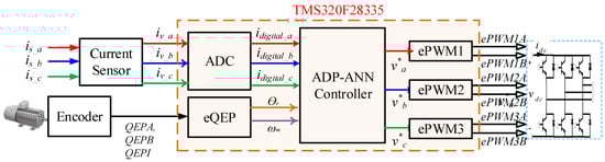
Figure 8.
Hardware structure of the DSP-based NN control system.
5. Software Implementation of DSP-Based Control Algorithm
The DSP-based control algorithm for the IPM motor is coded in C, compiled into assembly language, and then loaded into TMS320F28335 by using the TI Code Composer Studio (CCS). Overall, the software implementation includes the definition of global parameters, the main function, and functions that are related to PI or NN control. The global parameters include a sampling time of 0.1 ms, the inverter switching frequency of 10 kHz, motor parameters (Table 1), PI controller gains, NN controller weights, etc.
5.1. Implementation of the DSP Main Function
In the main function (Figure 9), the Peripheral Module Setup block performs a setup of the ADC module, eQEP module, and three ePWM modules for generation of PWM pulses, and the Interrupts Setup block setups an interrupt mechanism that is based on the sampling time that is specified for the PI or NN controller. The interrupt service routine (ISR) is defined and used to trigger the peripheral modules, as well as the conventional PI or NN control sub-function at each sampling interval. Figure 9 shows the flowchart of the main function. Details regarding the implementation of the PI or NN control sub-function in response to each interruption are presented below.
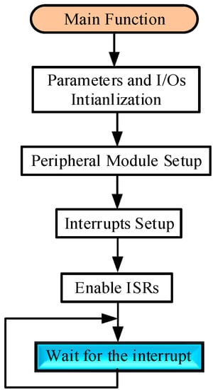
Figure 9.
Main function flowchart of the DSP-based microcontroller system.
5.2. Implementation of PI or NN Control Module
The PI or NN control Module is called or triggered by the interruption that is controlled by the ISR that is defined in the main function according to the sampling time of 0.1 ms used in this paper. After the PI or NN control function is called, it will first read the rotor position and speed of the IPM motor from the eQEP module and convert them into electrical angular position and speed of the motor in rad and rad/s, respectively. Subsequently, the PI or NN control module reads the digital three-phase motor current signals that are stored in the ADC result registers and recovers the obtained signals to the original motor current signals that are based on (13) and (14).
Afterwards, the three-phase currents are applied on the Park transformation [15] to acquire the d- and q-axis currents, id and iq, based on the rotor position obtained from the eQEP module. The d-axis current reference is manually given and the q-axis current reference is generated from a speed-loop PI controller that is based on the error between the desired and actual motor speed. id and iq are then subtracted from their references to get the errors, as well as the integrals of error signals, respectively.
For the conventional standard PI control method, each of the error signals is multiplied by a proportional gain, kpd or kpq, and each of the integrals of error signals is multiplied by an integral gain, kid or kiq. Subsequently, the compensation terms are applied to formulate the d- or q-axis control voltage for the IPM motor. The resultant d- and q-axis control voltage is normalized over the peak six-step fundamental voltage and is then sent to the SVPWM function, which generates three-phase control voltages, v*a, v*b, and v*c, to the ePWM modules to generate driving pulses to control the IPM motor inverter.
For the NN control method, the four signals, error signals and integrals of error signals, are formed into a vector that is to be used as the input to the NN control function. At the input layer of the NN, the input vector elements are divided by the appropriate gains, and the hyperbolic tangents are then used on them (Figure 3). The outputs of the input layer feed forward to the two hidden layers, each having six nodes, by multiplying the weight matrices and then go through hyperbolic tangent function at each node. Finally, the outputs of the neural network at the output layer are sent to the SVPWM function which generates three-phase control voltages, v*a, v*b, and v*c, to the ePWM modules to generate driving pulses to control the IPM motor inverter.
It is notable that the hyperbolic tangent function is rather time consuming in a DSP application, since truncated series expansions are often used for its calculation [31]. For the clock of TMS320F28335 at 150 MHz, each tanh function will take approximately 5 µs to compute. As the hyperbolic tangent function is applied 18 times totally per interruption for the NN controller that is shown in Figure 3, a significant amount of time is needed for its computation, which dominates most of the computing time for the NN. A simplified fast and approximate tanh function is employed by using the continued fraction to overcome the challenge, as shown below [32]:
(15) can be simplified as (16), which can be easily implemented by a DSP.
As (16) only contains 13 multiplications and summations, as well as one division, so that the processing time can be reduced to 0.16 µs with at least 93% accuracy within the NN operating range, so that the performance of the NN controller is not affected.
5.3. SVPWM Implementation
The generated d- and q-axis control voltages are sent to the SVPWM function (Figure 10). In this function, v*d and v*q are transformed into α-β domain as a vector within the modulation regions, as shown in Figure 4. Assume that the vector has a modulation angle γ and amplitude Vref. Based on γ, Figure 4 shows the modulation vector is put in one of the six sectors. Subsequently, depending on the amplitude Vref, a three-phase control voltage v*abc is generated as the final control signal sent into ePWM modules. If MI exceeds a specific value corresponding to the boundary of the SVPWM linear modulation region, as shown in Figure 4, the modulation vector goes into over-modulation regions and both γ and the amplitude are then adjusted based on the over-modulation algorithm [6], which requires an adjustment of v*abc generated above, accordingly.
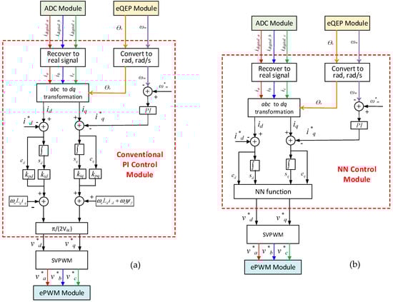
Figure 10.
Conventional standard proportional-integral (PI) and NN control modules. (a) Conventional standard PI control module. (b) NN control module. Each of the PI and NN control modules is only executed each time a sampling-controlled interrupt is generate.
6. Experiment Results
Hardware experiments were conducted over the TMS320F28335 cascaded speed- and current-loop control platform developed above (Section 4 and Section 5) to validate the effectiveness of the DSP-based NN controller and compare it with the conventional PI controller. The inner current-loop PI controller is tuned based on the description that is shown in Section 3.2, and the inner current-loop NN controller is trained based on the description of Section 3.3 and the motor parameters that are shown in Table 1. The outer speed-loop PI controller is tuned by using the MATLAB PID tuner function. As shown in Figure 10, the speed-loop controller generates the q-axis reference current, while the d-axis current reference is manually given. However, due to the speed and current limitations of our laboratory motor, a positive d-axis is used in this paper, which would allow for us to able to evaluate the IPM motor performance in over-modulation regions without violating speed and current limitations of the laboratory motor. Even so, our simulation study showed that the motor performance using positive d-axis current for over-modulation evaluation is equivalent to that while using negative d-axis current for over-modulation evaluation, as obtained and shown below. As explained at the end of Section 3, we plan to evaluate the performance of a more practical EV IPM motor under the NN control in the future when the motor is available, and compare the NN control with the conventional control.
Both the NN and conventional PI controllers were tested for a comparison evaluation while using the same SVPWM and the same strategy to limit the increase of the reference currents to prevent the motor inverter from operating beyond the six-step modulation region. During the experiment, the actual values of the motor parameters could be different from the nominal values that are shown in Table 1, as reported in many previously published papers [33]. Even so, the NN control shows a strong adaptive ability to handle the parameter uncertainties. Figure 10 presents an experiment result. The test sequence is scheduled as the following: The d-axis current reference is initially −3 A and it alters to 6 A around 20 sec The motor speed reference starts at 600 rpm, then increases to 1200 rpm and 3800 rpm at 10 sec and 30 sec, and then reduces to 1000 rpm at 50 sec. When the speed reaches 3800 rpm, the motor operates in over-modulation regions.
As the result shows, the NN controller can correctly track the current and speed references and achieve better power quality in the motor stator current for the motor inverter operating in the linear modulation region. In the over-modulation regions between 30 to 50 sec, more ripples appeared in the actual d- and q-axis currents due to the limited control ability that is caused by the SVPWM in over-modulation regions, as discussed in Section 2.4. However, in the same working conditions, the NN controlled stator current distortion is much less than the conventional one, especially when operating in over-modulation regions. Additionally, when the speed reference changes, the NN controller has better transient performance (Figure 11c,d). Overall, the hardware experiment proves the feasibility of the DSP based NN controller to control an IPM motor, as well as its reliability and high performance in both the linear and over-modulation regions as compared to the conventional standard vector controller. We anticipate that the proposed NN control would offer better performance for a practical EV IPM motor from the evaluation study over the laboratory test motor, especially under the typical high rpm speed for the EV motor operating in over-modulation modes.
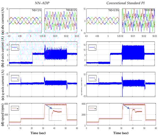
Figure 11.
NN vs. conventional IPM motor control comparison: (a) three-phase motor current and THD, (b) d-axis current, (c) q-axis current, and (d) motor speed.
7. Conclusions
IPM motors are widely used in electric drive applications, particularly in electric drive vehicles and drones. This paper presents a DSP implementation of ADP-based optimal control that is based on artificial neural networks for vector control of IPM motors operating in linear and over-modulation modes. The paper describes how to implement the ADP-based vector control through an artificial neural network that is trained as a recurrent neural network to achieve optimal and predictive control capabilities. Subsequently, the paper focuses on how to implement the conventional standard PI and ADP-based NN control by using a low cost TI TMS320F28335 DSP chip as well as the differences between the two. These include DSP hardware development and configuration, and software development to implement the DSP-based PI and NN control algorithms. In particular, special techniques are developed in the paper to significantly reduce the computing time of the NN control algorithm over the DSP chip. Hardware experiments are conducted to validate the effectiveness and performance of the NN controller for a laboratory IPM motor over the developed DSP system, which shows that it is feasible for realizing the NN control while using a low cost DSP chip. The performance evaluation demonstrates that, when compared to the conventional standard vector-control method, the NN-ADP vector control approach produces a faster response speed, lower overshoot, better power quality, and lower current and torque ripples for IPM operation in both the linear and over-modulation regions. The success of the DSP-based hardware experiments makes it possible to implement the ADP-based NN controller in real-life IPM motors. We also plan to conduct more comparison studies in the future for difference sizes of motors to investigate how the advantage of the NN control would benefit the operation of an IPM motor in steady and dynamic conditions, especially for the motor operating in over-modulation modes under a high rpm speed of a typical EV IPM motor.
Author Contributions
Conceptualization and methodology, Y.S. and S.L.; software, Y.S.; experiments and validation, Y.S., M.R., B.J. and Y.G.; formal analysis and investigation, Y.S. and S.L.; supervision, project administration and funding acquisition, S.L. and B.B.
Funding
This research was funded by the Center of Advanced Vehicle Technology, The University of Alabama.
Acknowledgments
This work was supported in part by the Center of Advanced Vehicle Technology.
Conflicts of Interest
The authors declare no conflict of interest.
References
- Ankit Singh Pundir. Electric Vehicle Market—Global Opportunity Analysis and Industry Forecast, 2017–2023. Available online: https://www.alliedmarketresearch.com/electric-vehiclemarket (accessed on 21 May 2018).
- Pellegrino, G.; Vagati, A.; Guglielmi, P.; Boazzo, B. Performance comparison between surface-mounted and interior PM motor drives for electric vehicle application. IEEE Trans. Ind. Electron. 2012, 59, 803–811. [Google Scholar] [CrossRef]
- Rahman, M.A.; Masrur, M.A. Advances on IPM technology for hybrid electric vehicles. In Proceedings of the 2009 IEEE Vehicle Power and Propulsion Conference, Dearborn, MI, USA, 7–11 September 2009. [Google Scholar]
- Islam, M.S.; Husain, I.; Mikail, R. Slotless lightweight motor for drone applications. In Proceedings of the 2017 IEEE ECCE, Cincinnati, OH, USA, 1–5 October 2017; pp. 5041–5048. [Google Scholar]
- Zhou, K.; Wang, D. Relationship between space-vector modulation and three-phase carrier-based PWM: A comprehensive analysis. IEEE Trans. Ind. Electron. 2000, 49, 186–196. [Google Scholar] [CrossRef]
- Lee, D.; Lee, G. A novel overmodulation technique for space-vector PWM inverters. IEEE Trans. Power Electron. 1998, 13, 1144–1151. [Google Scholar]
- Liu, X.D.; Yu, H.S.; Yu, J.P. Combined Speed and Current Terminal Sliding Mode Control with Nonlinear Disturbance Observer for PMSM Drive. IEEE Access 2018, 6, 29594–29601. [Google Scholar] [CrossRef]
- Liu, J.; Li, H.; Deng, Y. Torque ripple minimization of PMSM based on robust ILC via adaptive sliding mode control. IEEE Trans. Power. Electron. 2017, 33, 3655–3671. [Google Scholar] [CrossRef]
- Wu, Y.; Li, G. Adaptive disturbance compensation finite control set optimal control for PMSM systems based on sliding mode extended state observer. Mech. Syst. Signal Process. 2018, 98, 402–414. [Google Scholar] [CrossRef]
- Kakosimos, P.; Abu-Rub, H. Predictive speed control with short prediction horizon for permanent magnet synchronous motor drives. IEEE Trans. Power. Electron. 2017, 33, 2740–2750. [Google Scholar] [CrossRef]
- Holtz, J. Advanced PWM and predictive control—An overview. IEEE Trans. Ind. Electron. 2016, 63, 3837–3844. [Google Scholar] [CrossRef]
- Li, S.; Fairbank, M.; Fu, X.; Wunsch, D.C.; Alonso, E. Vector Control of Permanent Magnet Synchronous Motor using Adaptive Recurrent Neural Networks. In Proceedings of the 2013 IEEE International Joint Conference on Neural Networks, Dallas, TX, USA, 4–9 August 2013. [Google Scholar]
- Sun, T.; Wang, J.; Koc, M. On Accuracy of Virtual Signal Injection based MTPA Operation of Interior Permanent Magnet Synchronous Machine Drives. IEEE Trans. Power Electron. 2017, 32, 7405–7408. [Google Scholar] [CrossRef]
- Sun, T.; Wang, J.; Chen, X. Maximum Torque Per Ampere (MTPA) Control for Interior Permanent Magnet Synchronous Machine Drives Based on Virtual Signal Injection. IEEE Trans. Power Electron. 2015, 30, 5036–5045. [Google Scholar] [CrossRef]
- Mohan, N.; Undeland, T.M.; Robbins, W.P. Power Electronics: Converters, Applications, and Design, 3rd ed.; John Wiley & Sons Inc.: Hoboken, NJ, USA, 2002. [Google Scholar]
- Modi, M.K.; Venugopal, S.; Narayanan, G. Space vector-based analysis of overmodulation in triangle-comparison based PWM for voltage source inverter. Sadhana 2013, 38, 331–358. [Google Scholar] [CrossRef]
- Zhou, C.; Yang, G.; Su, J. PWM Strategy With Minimum Harmonic Distortion for Dual Three-Phase Permanent-Magnet Synchronous Motor Drives Operating in the Overmodulation Region. IEEE Trans. Power Electron. 2016, 31, 1367–1380. [Google Scholar] [CrossRef]
- Kwon, Y.C.; Kim, S.; Sul, S.K. Six-Step Operation of PMSM With Instantaneous Current Control. IEEE Trans. Ind. Appl. 2014, 50, 2614–2625. [Google Scholar] [CrossRef]
- Mohan, N. Advanced Electric Drives—Analysis, Modeling and Control Using Simulink; Minnesota Power Electronics Research & Education: Minneapolis, MN, USA, 2001; ISBN 0-9715292-0-5. [Google Scholar]
- Ramakrishnan, R.; Islam, R.; Islam, M.; Sebastian, T. Real time estimation of parameters for controlling and monitoring permanent magnet synchronous motors. In Proceedings of the 2009 IEEE International Electric Machines and Drives Conference, Miami, FL, USA, 3–6 May 2009; pp. 1194–1199. [Google Scholar]
- Jiang, Y.; Jiang, Z. Robust Adaptive Dynamic Programming and Feedback Stabilization of Nonlinear Systems. IEEE Trans. Neural Netw. Learn. Syst. 2014, 25, 882–893. [Google Scholar] [CrossRef] [PubMed]
- KrishnaKumar, K.; Neidhoefer, J. Immunized Adaptive Critics for Level-2 Intelligent Control. In Proceedings of the IEEE International Conference on Systems, Man and Cybernetics, Orlando, FL, USA, 12–15 October 1997; pp. 856–861. [Google Scholar]
- Venayagamoorthy, G.K.; Harley, R.G.; Wunsch, D.C. Comparison of Heuristic Dynamic Programming and Dual Heuristic Programming Adaptive Critics for Neurocontrol of a Turbogenerator. IEEE Trans. Neural Netw. 2002, 13, 764–773. [Google Scholar] [CrossRef] [PubMed]
- Fu, X.; Li, S.; Fairbank, M.; Wunsch, D.C.; Alonso, E. Training recurrent neural networks with the Levenberg-Marquardt algorithm for optimal control of a grid connected converter. IEEE Trans. Neural Netw. Learn. Syst. 2014, 26, 1900–1912. [Google Scholar] [CrossRef] [PubMed]
- MotorSolver. 4 Pole IPM Type PM-AC Synchronous Motor Used for University Teaching Lab Dyno-Kits. Available online: http://motorsolver.com/wp/wp-content/uploads/2015/03/9-PRIUS-4POLE-IPM-SPECS-small.pdf (accessed on 16 January 2018).
- Hwang, M.H.; Han, J.H.; Kim, D.H.; Cha, H.R. Design and Analysis of Rotor Shapes for IPM Motors in EV Power Traction Platforms. Energies 2018, 11, 2601. [Google Scholar] [CrossRef]
- Texas Instruments. TMS320C28x Extended Instruction Sets Technical Reference Manual. Available online: http://www.ti.com/lit/ug/spruhs1a/spruhs1a.pdf (accessed on 15 October 2018).
- AKM Semiconductor Inc. CQ-209A: High-Speed Small-Sized Current Sensor. Available online: https://www.akm.com/akm/en/file/datasheet/CQ-209D.pdf (accessed on 15 October 2018).
- Texas Instruments. TMS320x2833x Analog-to-Digital Converter (ADC) Module Reference Guide. Available online: File:///C:/Users/student/Downloads/2260.TI_TMS320x2833x%20Analog-to-Digital%20Converter%20(4).pdf (accessed on 15 October 2018).
- Texas Instruments. TMS320x2833x, 2823x Enhanced Quadrature Encoder Pulse (eQEP) Module Reference Guide. Available online: http://www.ti.com/lit/ug/sprug05a/sprug05a.pdf (accessed on 15 October 2018).
- Mohamadian, M.; Nowicki, E.; Ashrafzadeh, F.; Chu, A.; Sachdeva, R.; Evanik, E. A novel neural network controller and its efficient DSP implementation for vector-controlled induction motor drives. IEEE Trans. Ind. Appl. 2003, 39, 1622–1629. [Google Scholar] [CrossRef]
- Berndt, B.C.; Gesztesy, F. Continued Fractions: From Analytic Number Theory to Constructive Approximation; American Mathematical Society: Providence, RI, USA, 1999. [Google Scholar]
- Huynh, T.A.; Hsieh, M.F. Performance Analysis of Permanent Magnet Motors for Electric Vehicles (EV) Traction Considering Driving Cycles. Energies 2018, 11, 1385. [Google Scholar] [CrossRef]
© 2019 by the authors. Licensee MDPI, Basel, Switzerland. This article is an open access article distributed under the terms and conditions of the Creative Commons Attribution (CC BY) license (http://creativecommons.org/licenses/by/4.0/).