Article

Effect of Platform Motion on Aerodynamic Performance and Aeroelastic Behavior of Floating Offshore Wind Turbine Blades

Department of Aerospace Engineering, Korea Advanced Institute of Science and Technology (KAIST), 291 Daehak-ro, Yuseong-gu, Daejeon 34141, Korea
*
Author to whom correspondence should be addressed.
Energies 2019, 12(13), 2519; https://doi.org/10.3390/en12132519
Submission received: 5 June 2019 / Revised: 26 June 2019 / Accepted: 27 June 2019 / Published: 30 June 2019
(This article belongs to the Section A3: Wind, Wave and Tidal Energy)

Abstract

:
In the present study, a numerical framework for predicting the aerodynamic performance and the aeroelastic behavior of floating offshore wind turbine rotor blades involving platform motion was developed. For this purpose, the aerodynamic and structural analyses were conducted simultaneously in a tightly coupled manner by exchanging the information about the aerodynamic loads and the elastic blade deformations at every time step. The elastic behavior of the turbine rotor blades was described by adopting a structural model based on the Euler-Bernoulli beam. The aerodynamic loads by the rotor blades were evaluated by adopting a blade element momentum theory. The numerical simulations were conducted when the platform of the wind turbine independently moves in each of the six degrees-of-freedom directions consisting of heave, sway, surge, roll, pitch, and yaw. It was observed that flexible blades exhibit complicated vibratory behaviors when they are excited by the aerodynamic, inertia, and gravitational forces simultaneously. It was found that the load variation caused by the platform surge or pitch motion has a significant influence on the flapwise and torsional deformations of the rotor blades. The torsional deformation mainly occurs in the nose-down direction, and results in a reduction of the aerodynamic loads. It was also found that the flapwise root bending moment is mainly influenced by the platform surge and pitch motions. On the other hand, the edgewise bending moment is mostly dictated by the gravitational force, but is not affected much by the platform motion.

1. Introduction

These days, wind became more popular as one of the renewable energy sources. It is sustainable, widely-distributed, and eco-friendly. In addition, the wind power system does not produce any greenhouse gas emission during the operation. Because of these reasons, the energy resource based on conventional fuels primarily used in the past has recently been replaced by wind energy by a significant portion. According to Wind Europe’s Central Scenario [1], 106 GW of wind power capacity was installed in Europe between 2006 and 2016. In the same period, the US and China have installed 71 GW and 156 GW, respectively. The EU targets for 323 GW of cumulative wind energy capacity by 2030, including 253 GW and 70 GW onshore and offshore, respectively. This is equivalent to 29.6% of the EU’s total electrical power demand.
The wind energy market has so far been dominated by onshore wind turbines installed on the ground. However, onshore wind has a limited potential due to its relatively poor quality and the lack of turbine install location. Accordingly, offshore wind power systems attract more attention these days, since offshore wind is stronger and is more consistent than onshore wind. Moreover, construction of large-scale wind farms is more feasible in offshore. Consequently, a variety of offshore wind turbine concepts are currently under development around the world.
Offshore wind turbines are classified into either bottom-fixed or floating depending on the install location [2]. Bottom-fixed wind turbines have a fixed foundation on the seabed, and are generally installed in shallow water areas of up to 60-m in depth. Meanwhile, floating wind turbines are mounted on a platform floating on the water, and are usually installed in the deep-water area where bottom-fixed wind turbines are not feasible. Floating offshore wind turbines have an extensive potential compared to bottom-fixed types, since water depth or seabed condition is not a consideration for a site selection. However, they are continuously under the influence of wave and wind, which can cause movement of the platform. The consecutive oscillation resulting from the platform motion not only alters the aerodynamic performance of the turbine, but also leads to a structural vibration of the turbine components such as the blades, shaft, and tower.
Several studies have been previously undertaken to accurately predict the aerodynamic performance of floating offshore wind turbines considering the platform motion. Vaal, Hansen, and Moan [3] investigated the effects of a periodic surge motion on the integrated loads and the induced velocity of the wind turbine rotor by using a blade element momentum theory coupled with a quasi-steady wake model and a dynamic inflow model. Tran and Kim [4,5] conducted numerical simulations of a floating offshore wind turbine under a periodic platform surge and pitch motions at various frequencies and amplitudes, and examined the effect of vortex-wake-blade interaction. Tran and Kim [6] also investigated the dynamic response of a floating offshore wind turbine by using a coupled aero-hydrodynamic approach. In their study, the aerodynamic loads of the rotor, the platform dynamic response, and the mooring line tension were calculated.
Even though some meaningful results were obtained from the previous studies [3,4,5,6] for the aerodynamic load prediction of floating offshore wind turbines, the rotor blades were assumed to be rigid, and the effects of elastic blade deformation were not properly considered. Rodriguez and Jaworski [7] developed an aeroelastic framework for evaluating the impact of the blade elasticity on the near-wake formation and its linear stability for onshore and offshore wind turbine configurations. However, in their study, only flapwise bending deformation was examined based on a linearized elastic structural model, and the blade deformations in the other directions were not considered. Since elastic rotor blades deform in every axial, lead-lag, flapping, and torsional directions, and they are all non-linearly coupled together, it is important to consider those deformations simultaneously [8]. Torsional deformation changes the blade effective angle-of-attack, and, thus, has a significant influence on the blade aerodynamic loads and the overall rotor performance.
In the present study, the rotor aerodynamic performance, the blade elastic behavior, and the mutual interaction of the two were investigated for a floating offshore wind turbine under periodic platform motions. To calculate the aerodynamic loads produced by the rotor blades, a blade element momentum theory was applied. For the prediction of the elastic blade deformations, a structural model was developed based on a nonlinear Euler-Bernoulli beam undergoing axial, lead-lag, flapping, and torsional deformations. The aerodynamic and structural analyses were conducted simultaneously in a tightly coupled manner by exchanging the information about the aerodynamic loads and the elastic blade deformations at every time step. The motion of the floating offshore turbine was prescribed by the six degrees-of-freedom (6DoF) platform motions. At first, the calculations were conducted for a fixed-platform wind turbine, and the aerodynamic loads and the elastic blade deformations were examined under various operating conditions. Next, the aerodynamic load variations of the rigid rotor blades were calculated when the platform is in periodic motions. Lastly, the effects of periodic platform motions on the aerodynamic performance and the aeroelastic behavior of the flexible rotor blades were investigated, along with the blade root bending moments. Since the tower and the platform are relatively more rigid compared to the blades, the effects of the flexibility of the two turbine components were not considered in the present study.

2. Numerical Methods

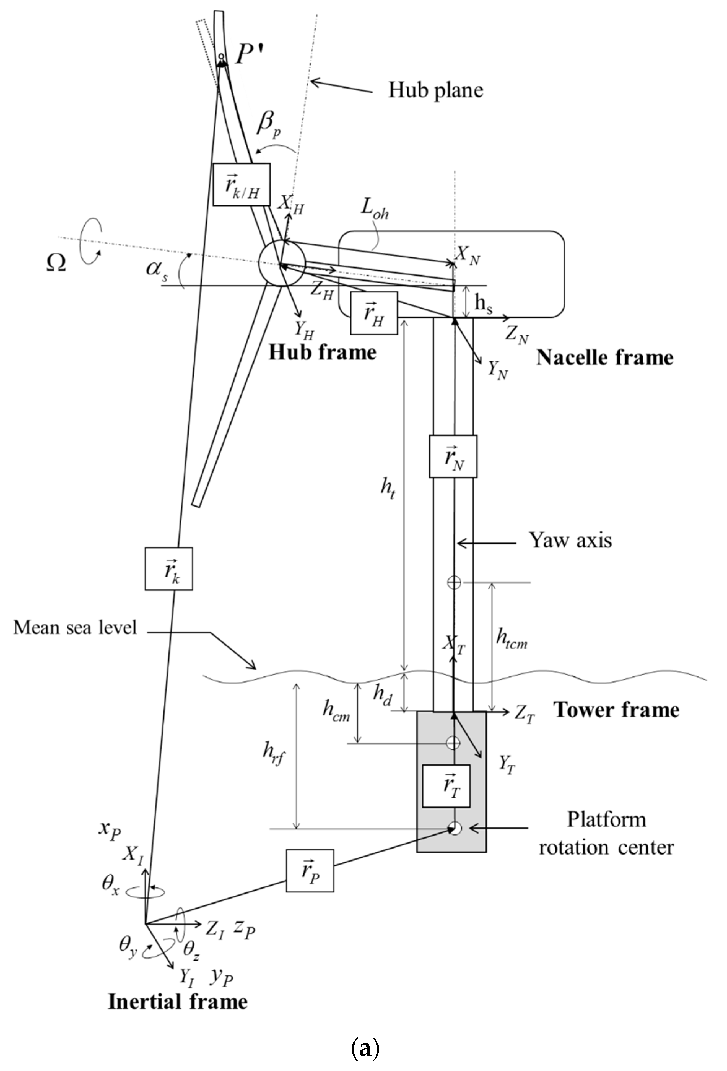
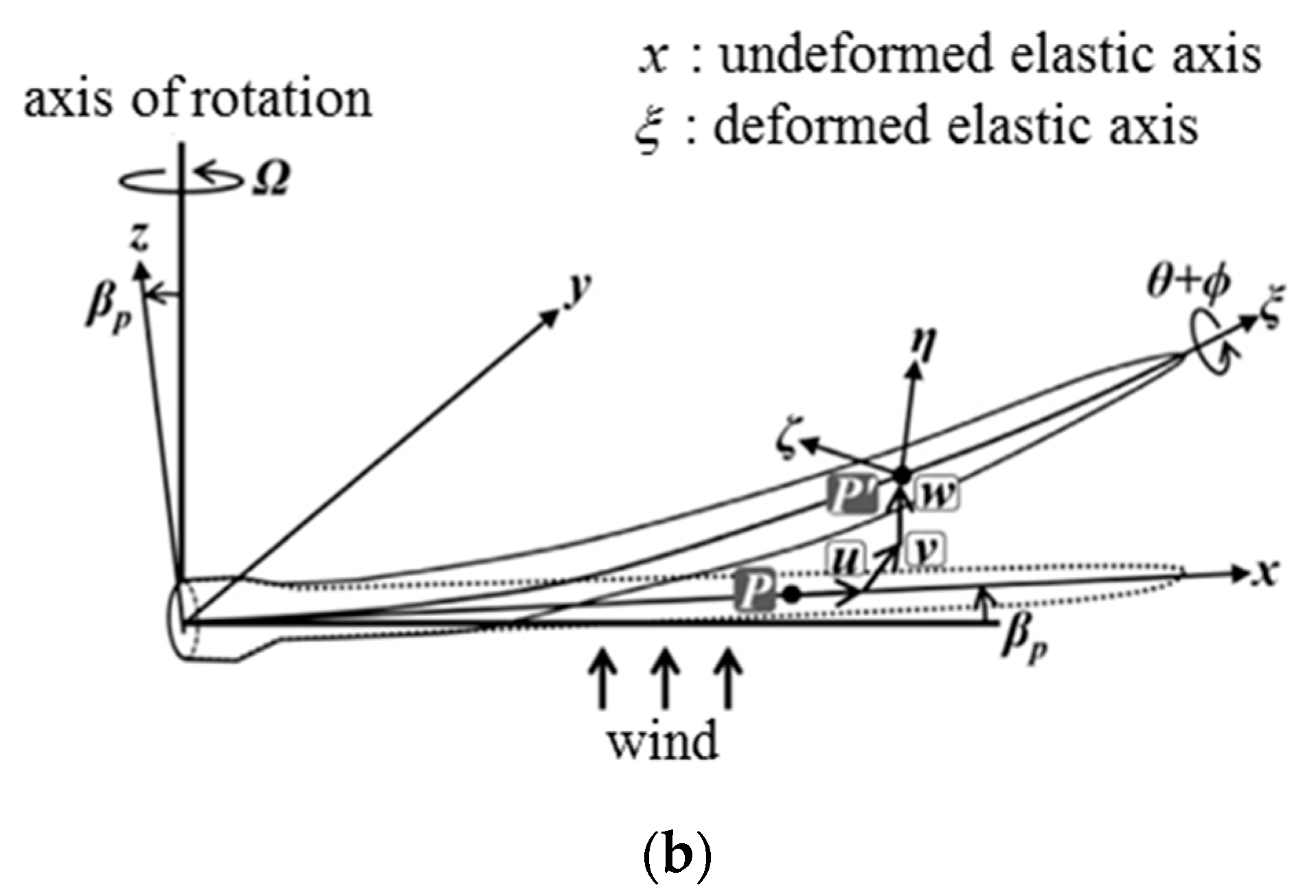
2.1. Derivation of Structural Equations of Motion

The structural model for predicting the blade elastic behavior is based on a second-order nonlinear Euler-Bernoulli beam. Figure 1a,b show the coordinate systems for the floating offshore wind turbine and the blade deformation kinematics [9], respectively. When the blade deforms, as shown in Figure 1b, an arbitrary point P on the undeformed blade is moved to a point P by the axial ( u ), lead-lag ( v ), and flapping ( w ) deformations. Then, the blade cross-section containing P undergoes rotations of pitch control angle ( θ ) and torsional deformation ( ϕ ) about the deformed elastic axis ( ξ ). To conduct aeroelastic analyses for the floating offshore wind turbine, the 6DoF equations of the platform motion defined in the inertial frame need to be combined with the formulation governing the blade elastic motion [10]. The transformation matrix from the inertial frame to the tower frame ( T T I ) with a small angle approximation can be achieved by the following equation.
{ I T J T K T } = T T I { I I J I K I } , T T I = [ 1 θ z θ y θ x θ y θ z θ x θ y θ z + 1 θ x θ y + θ x θ z θ y θ z θ x 1 ]
To derive the equations governing the blade elastic behavior, Hamilton’s variational principle was adopted. The generalized Hamilton’s principle, applicable to non-conservative systems, can be expressed by the equation below.
t 1 t 2 ( δ U δ T δ W ) = 0 ,
where δ U , δ T , and δ W are the variations of the strain energy, the kinetic energy, and the virtual work done by the applied aerodynamic and gravitational loads, respectively. Since the explicit expression of the equations considering all nonlinear terms is extremely lengthy and complicated, an ordering scheme [10] was applied to simplify the equations by neglecting relatively less important terms. The orders of magnitude of the non-dimensional quantities related to the platform motion can be summarized by the equation below.
x p R , y p R , z p R , θ x , θ y , θ z = O ( ε ) x ˙ p Ω R , y ˙ p Ω R , z ˙ p Ω R , x ¨ p Ω 2 R , y ¨ p Ω 2 R , z ¨ p Ω 2 R , θ ˙ x Ω , θ ˙ y Ω , θ ˙ z Ω , θ ¨ x Ω 2 , θ ¨ y Ω 2 , θ ¨ z Ω 2 = O ( ε 3 / 2 )
The orders of magnitude for the non-dimensional parameters related to the 6DoF platform motion are set to O ( ε ) , and their first and second time derivatives are set to O ( ε 3 / 2 ) . The orders of the terms related to the wind turbine configuration in Figure 1a, such as tower height, overhang length, shaft tilt angle, and pre-cone angle, are set as the same to those in the beam equation suggested by Hodges [10].
The strain energy terms are not affected by the platform motion, and, therefore, the equation can be obtained by applying the strain-displacement relations based on an Almansi strain and their variations [9,10].
The variation of kinetic energy in Equation (2) can be expressed by the equation below.
δ T = 0 R A ρ s r ¨ k δ r k d η d ς d x
The kinetic energy equations are obtained by the acceleration vector ( r ¨ k ) and the virtual displacement ( δ r k ) of r k , which is the position vector of an arbitrary point ( P ) on the deformed blade defined in the inertial frame, as shown in Figure 1a.
The virtual work done by the applied loads, which are the aerodynamic and gravitational loads, can be expressed by the equation below.
δ W = 0 R [ ( L u g + L u A ) δ u + ( L v g + L v A ) δ v + ( L w g + L w A ) δ w + ( L ϕ g + L ϕ A ) δ ϕ ] d x ,
where L u , L v , and L w are the applied loads at each blade section along the x , y , and z directions, respectively. L ϕ represents the pitching moment about the undeformed axis.

2.2. Discretization Method

To obtain the discretized equations governing the blade elastic deformation, a finite-element method (FEM) was adopted. The blade is divided into a number of finite elements, and the corresponding elemental matrices and vectors are assembled to construct the global nonlinear equations shown below.
M b q ¨ + G b q ˙ + K b q + M b P x ¨ P + C b P x ˙ P + K b P x P = F 0 + F N L + F g r a v + F a e r o ,
Here, M b , G b , and K b are the blade mass, gyroscopic, and stiffness matrices, respectively. Also, M b P , C b P , and K b P are the terms representing the blade-platform coupled mass, damping, and stiffness matrices, respectively, which arise additionally to accommodate the platform motion. The terms on the left-hand side of Equation (6) are linear, and all the nonlinear terms are included in F N L on the right-hand side. x P is the vector representing the translational and rotational displacements of the platform following its motion.
x P T = [ x P , y P , z P , θ x , θ y , θ z ]
F 0 indicates the inertia force arising from the blade azimuthal rotation and the rigid motion for blade pitch control. F a e r o and F g r a v are the applied loads on the blade by the aerodynamic and gravitational forces, which come from the virtual work in Equation (5). The nonlinear equations of motion in Equation (6) are numerically solved by using the Newmark- β time integration method [11].

2.3. Aerodynamic Load Prediction

In the present study, the blade element momentum theory [12,13] was adopted to calculate the aerodynamic forces acting on the wind turbine rotor blades. This method is numerically efficient, and is simple to apply. For calculating the sectional aerodynamic loads, two-dimensional static airfoil data [14] was utilized. The induced downwash was estimated by using the momentum theory based on a linear inflow model [15]. The relative velocity between the free-stream and the rotating blades can be expressed by the equation below.
V b / F = V b V F where   V b / F = { U r U t U p } D , V b = { U r b U t b U p b } D , V F = { U r U t U p } D + { U r i U t i U p i } D
Here, V b indicates the rotating blade velocity considering the platform motion, and V F represents the sum of the free-stream velocity and the induced downwash. The tangential and perpendicular components of the relative velocity in the deformed frame were used to calculate the magnitude of the sectional velocity and the angle-of-attack.
In reality, a time lag exists between the air loads and the instantaneous angle-of-attack because of the build-up effect of the circulatory loads and the decay effect of the non-circulatory impulsive loads. These unsteadiness effects are known to arise from the trailing-edge shed wake and also from the propagation of the pressure disturbances [16,17]. In the present study, the unsteadiness was accounted for by adopting the indicial response method [16,17] considering a step change of the angle-of-attack and the pitch rate.

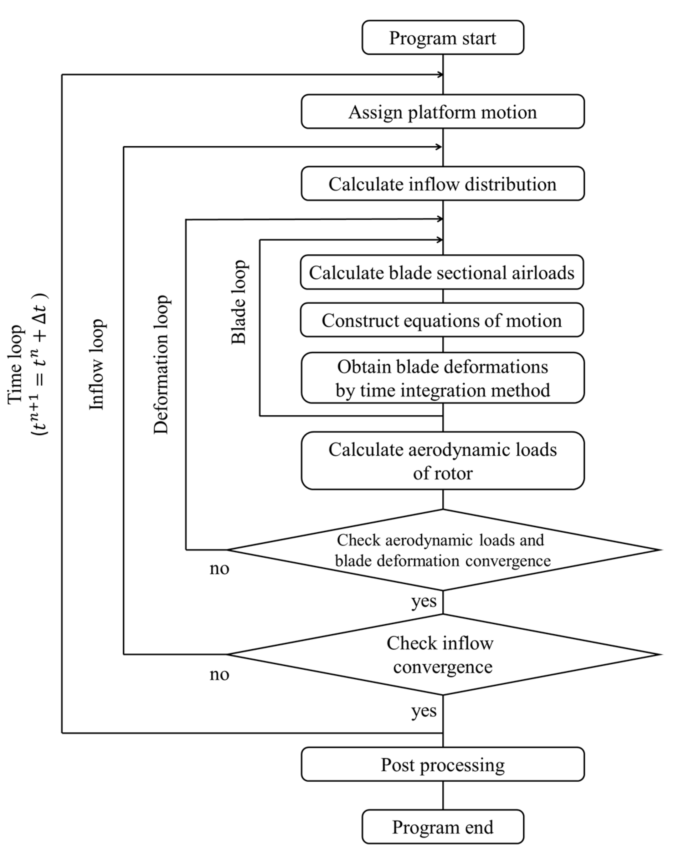
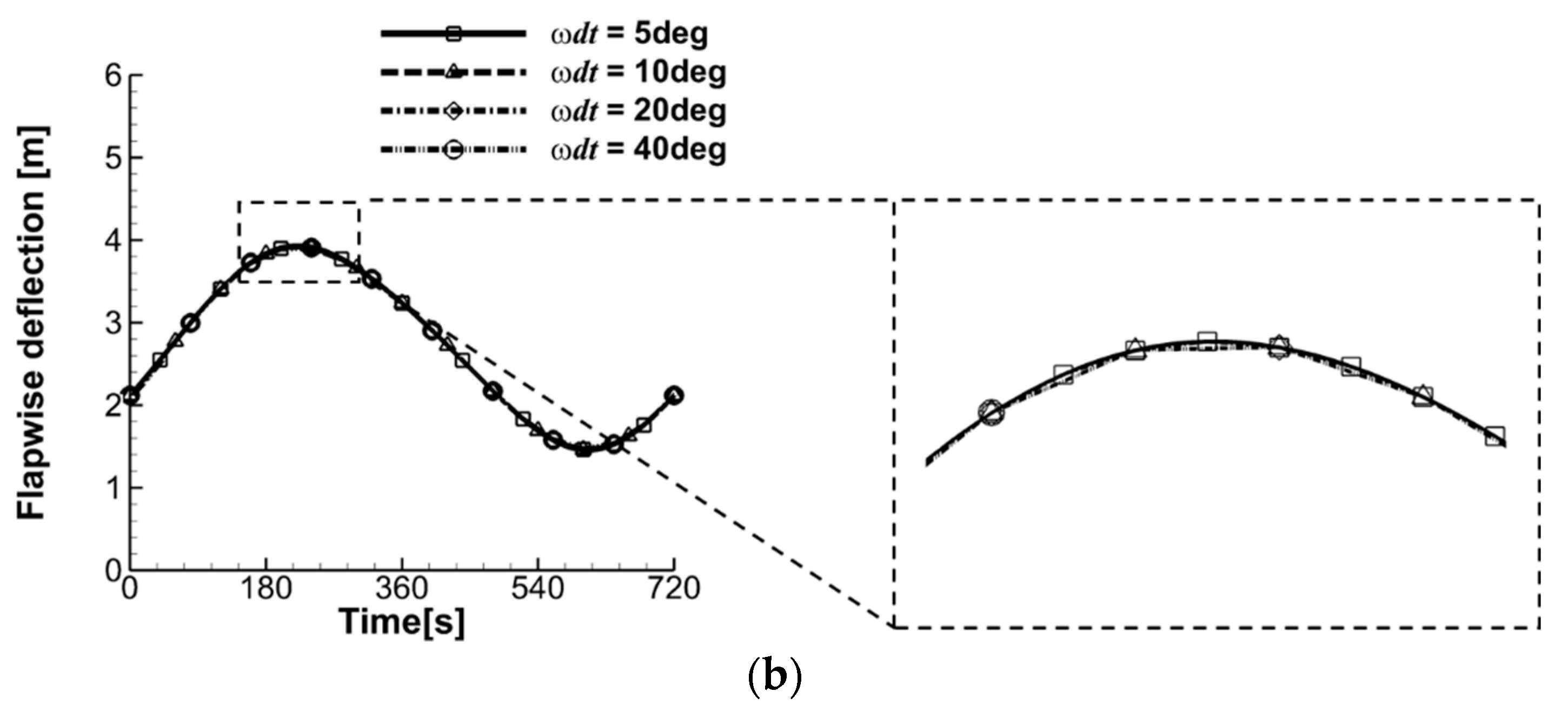
2.4. Coupling Methodology

When the floating offshore wind turbine is under a platform motion, strong mutual interaction exists between the rotor blade aerodynamics and its elastic behavior. To investigate this transient flow phenomenon accurately, in the present study, the aerodynamic and structural analyses were conducted simultaneously in a tightly coupled manner by exchanging the information about the aerodynamic loads and the elastic blade deformations at every time step.
Figure 2 shows the overall procedure for the coupled aeroelastic analyses of the floating offshore wind turbine rotor blades. At first, the platform motions are prescribed. Then, the sectional aerodynamic loads for each blade are calculated based on the two-dimensional static data. At the initial stage, the blade deformations and the induced downwash distribution of the rotor are assumed to be zero. This sectional airloads of the blades are provided in Equation (6), and the elastic blade deformations in the axial, edgewise, flapwise, and torsional directions are calculated. The information about the blade deformations are then transferred to the aerodynamic analysis routine, and the sectional aerodynamic loads of each blade are re-calculated for the deformed blade configuration. This process of the deformation loop is iteratively repeated until the averaged value of the root mean square errors of the blade deformations for all nodes becomes less than a given criterion. In the present study, 10 3 was specified.
After that, the inflow distribution is calculated again based on the converged solution of the rotor aerodynamic loads. Then the sectional aerodynamic loads and the elastic deformations of the rotor blades are re-calculated for the new inflow information. This procedure of the outer inflow loop is repeated until the root mean square error of the induced downwash for all blades becomes less than 10 4 . This completes the current time step, and the calculation is continued by considering the prescribed platform motion at the next time step.

3. Results and Discussion

In the present study, numerical analyses were carried out for the NREL 5 MW reference wind turbine. Initially, for the verification of the present framework, aeroelastic analyses of the bottom-fixed wind turbine rotor blades were carried out. Then aerodynamic load prediction of the floating offshore wind turbine under a platform surge motion was performed for rigid rotor blades. Next, aeroelastic analyses were conducted for the floating offshore wind turbine to investigate the effects of platform motions on the aerodynamic loads and the deformation of flexible rotor blades.
The gross properties of the NREL 5 MW reference wind turbine [14] are presented in Table 1. The wind turbine has a conventional three-bladed, upwind, blade-pitch-controlled rotor that exhibits a power rating of 5 MW at the rated-wind speed of 11.5 m/s.

3.1. Aeroelastic Analyses of Bottom-Fixed Wind Turbine Rotor Blades

At first, aeroelastic analyses of the bottom-fixed wind turbine rotor blades were conducted. In Figure 3, the rotor aerodynamic loads and the blade tip deformations are presented with varying wind speed. Below the rated wind speed, the thrust and torque gradually increase as the wind speed and the angular velocity of the blade increase, as shown in Figure 3a. Above the rated wind speed, pitch control in the nose-down direction is applied for a fixed angular velocity of 12.1 RPM, and, therefore, the torque remains constant and the thrust decreases. Accordingly, the largest blade deformations occur at the rated-wind speed where the thrust is maximized, as shown in Figure 3b. In addition, because of the flapwise deformation, the clearance between the tower and the blades is reduced from 0.2 R to 0.12 R at the rated wind speed. The results confirm that consideration of the elastic blade deformations is essential in the aerodynamic analyses of large-scale wind turbines. It is also shown in the figure that the present results are in good agreement with those of FAST [14] and a coupled CFD-CSD method [9]. However, small differences in the thrust and in the flapwise deformation are observed between FAST and the present method. These deviations are mainly due to the effect of the torsional deformation, which is not considered in FAST. When the nose-down torsional deformation is present, the thrust and the flapwise deformation are consequently reduced.

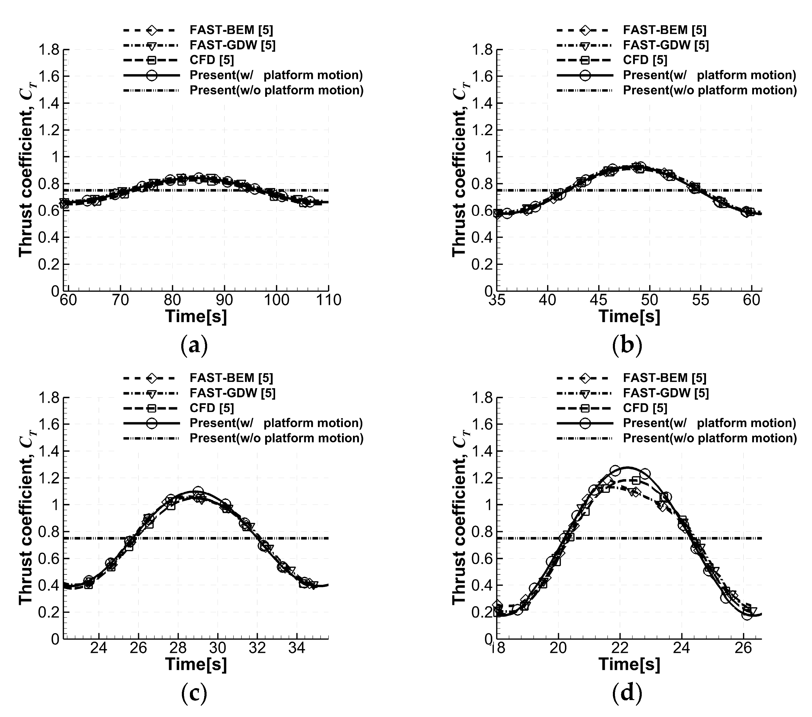
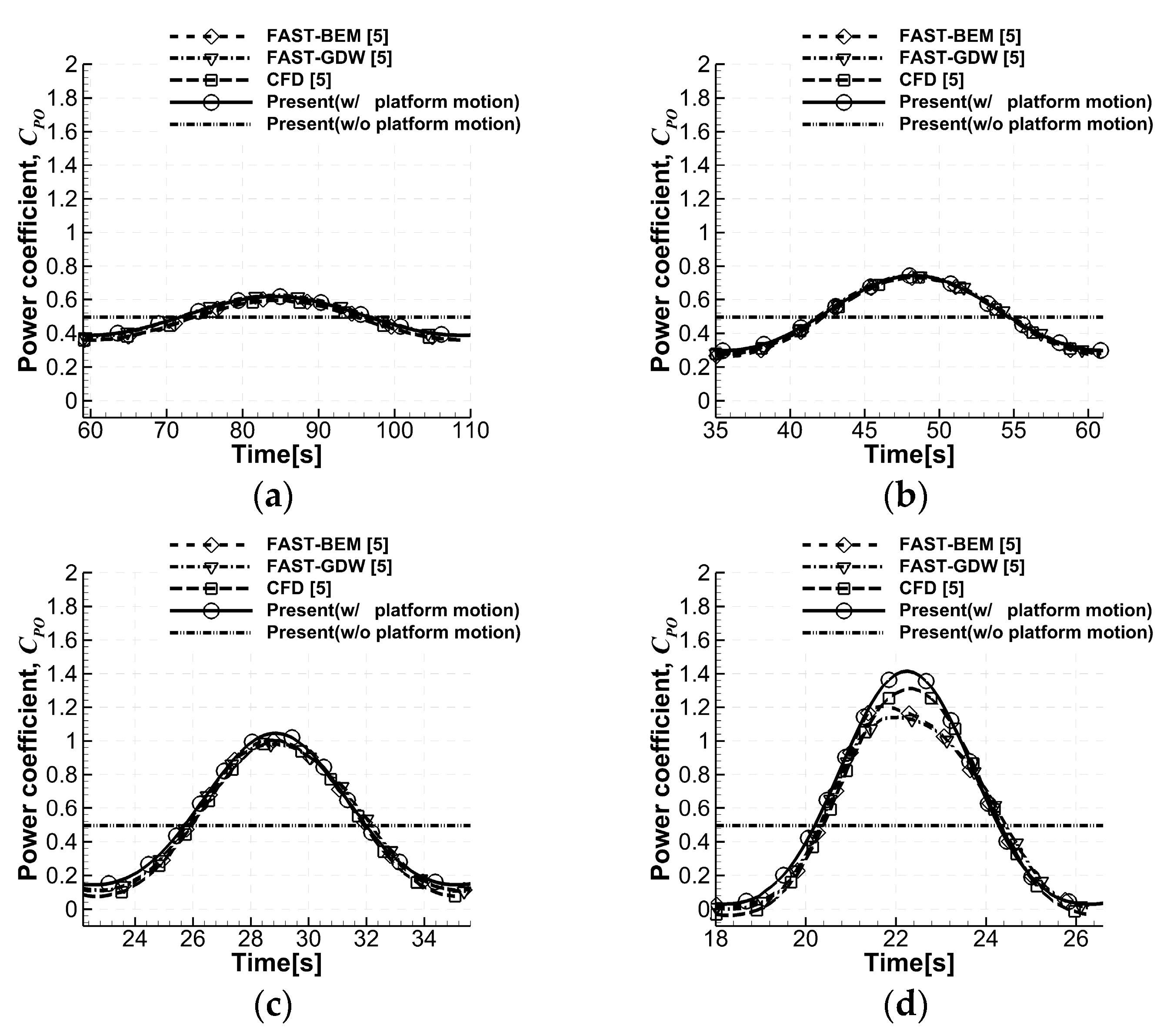
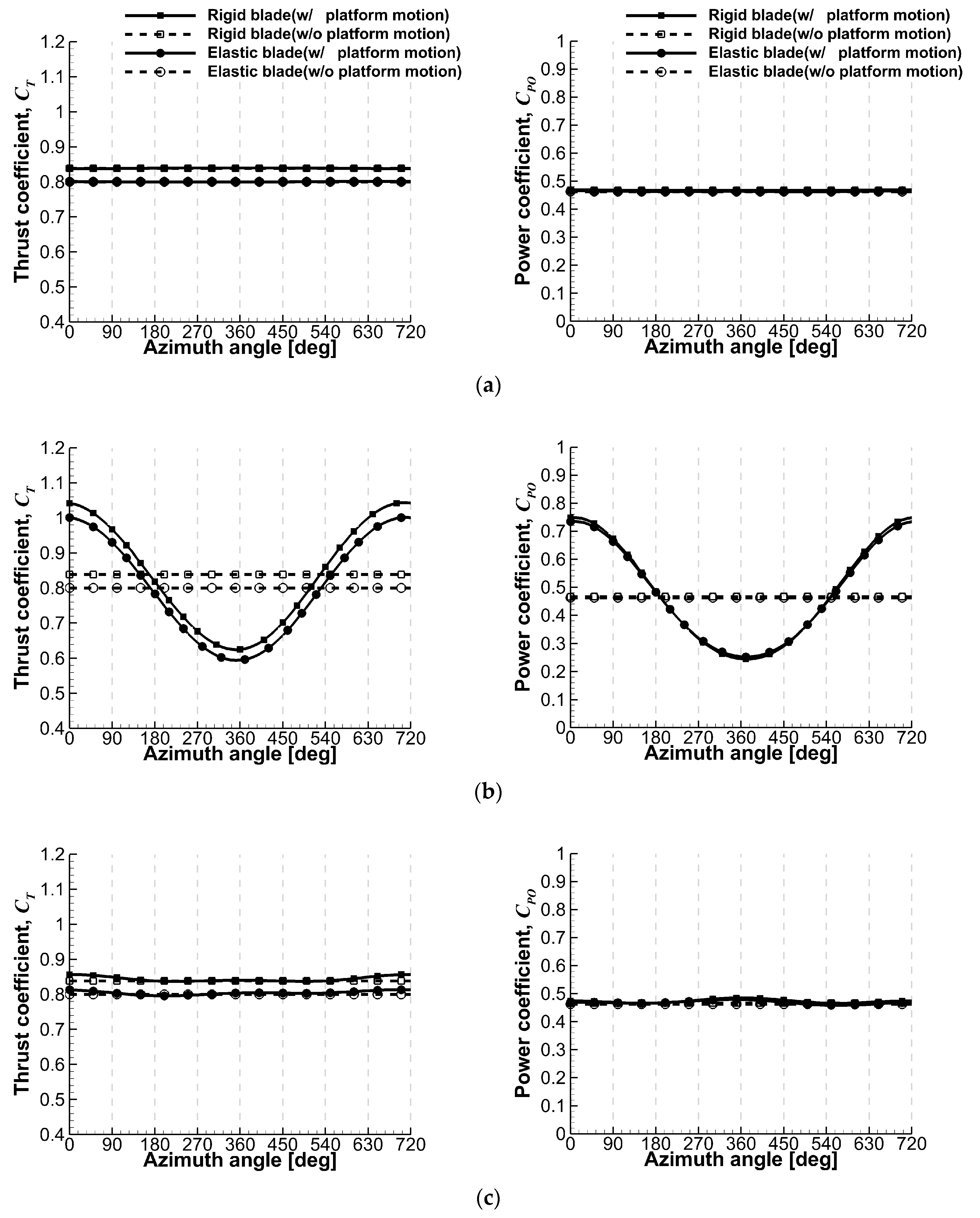
3.2. Aerodynamic Loads of a Floating Offshore Wind Turbine with Rigid Rotor Blades

Next, aerodynamic load variations due to a platform surge motion were investigated for a floating offshore wind turbine. In this case, all components of the wind turbine, including the rotor blades, tower, and rotor shaft were assumed to be rigid bodies. The results were compared with those of a previous study [5] by using both FAST and a CFD approach based on the three-dimensional Navier-Stokes equations. For the demonstration of the platform motion of the wind turbine, a sinusoidal function was applied as below.
D ( t ) = D 0 sin ( ω t )
In the present study, the platform surge motion with various oscillation frequencies, which are the same as those used in the previous study [5], were adopted for a comparison purpose. Table 2 shows the amplitudes and the frequencies of the platform motion. In Figure 4, the platform displacement, velocity, and acceleration are presented when the platform moves with an amplitude ( D 0 ) of 8 m and a frequency ( ω ) of 0.5 rad/s. The calculations were made at the rated-wind speed of 11.5 m/s. In this wind condition, the blade rotates with an angular velocity of 12.1 RPM, and the pitch control angle is set to zero degree.
Figure 5 and Figure 6 show the thrust and power coefficients for the various platform surge motion cases in Table 2. The results are also compared with other predictions [5]. It is shown that the aerodynamic loads significantly oscillate due to the platform surge motion, and the load variation becomes larger as the frequency of the platform motion increases. Overall, the present results compare very well with other predictions [5] by FAST and a CFD method. However, some deviation of the aerodynamic loads is observed as the platform oscillation frequency becomes larger, as shown in Figure 5d and Figure 6d. This is because conventional approaches, such as BEM or GDW, have limitations in accurately predicting the transient flow characteristics due to their theoretical assumptions [18], when compared to the CFD method. Except for the case with a high oscillating frequency of the platform, it was found that the present method is able to predict the aerodynamic load variation due to platform motions accurately.

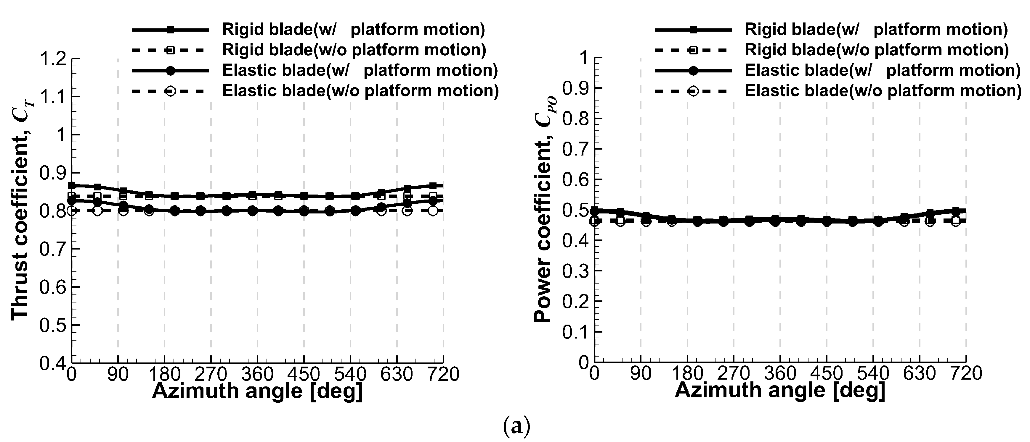
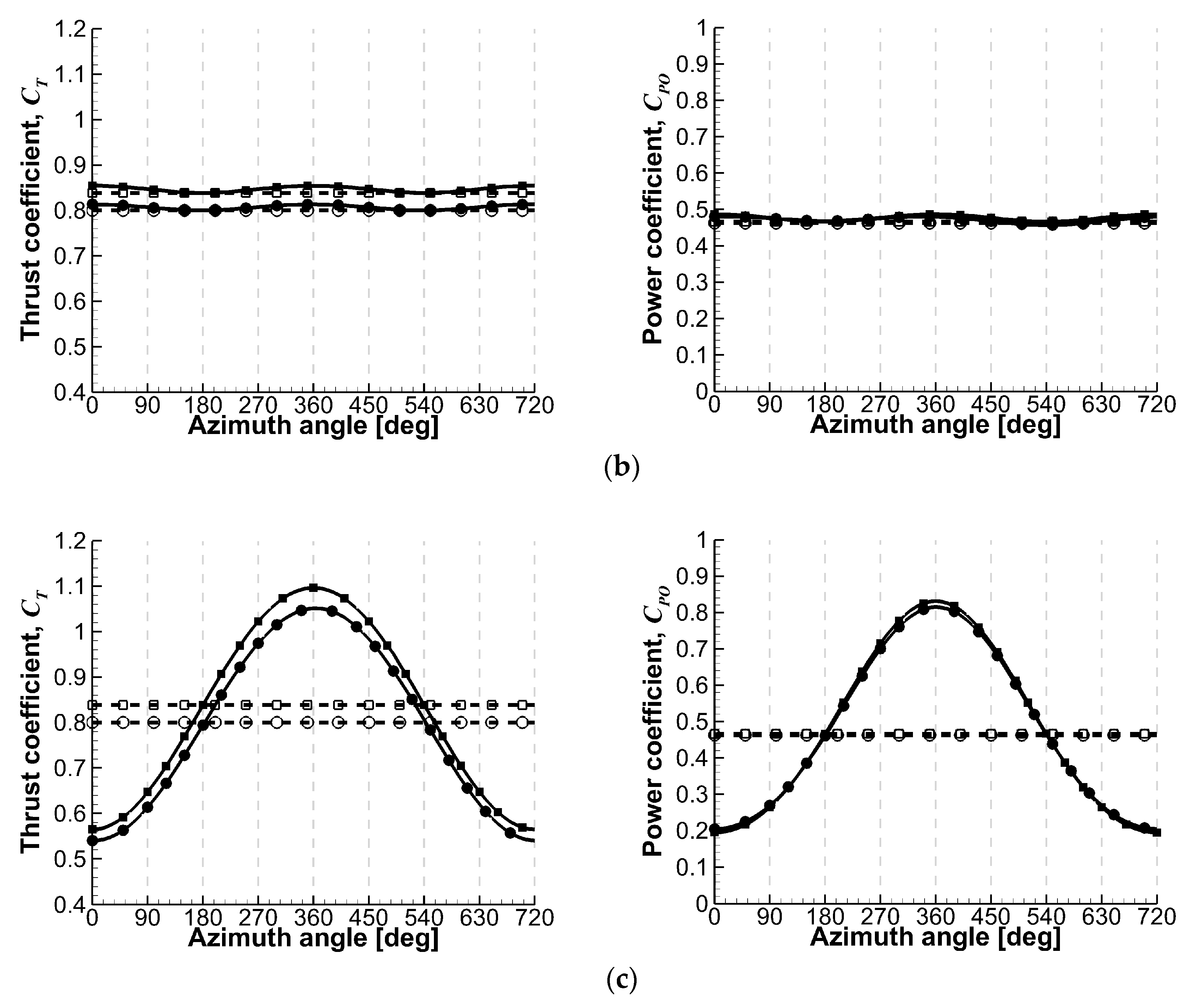
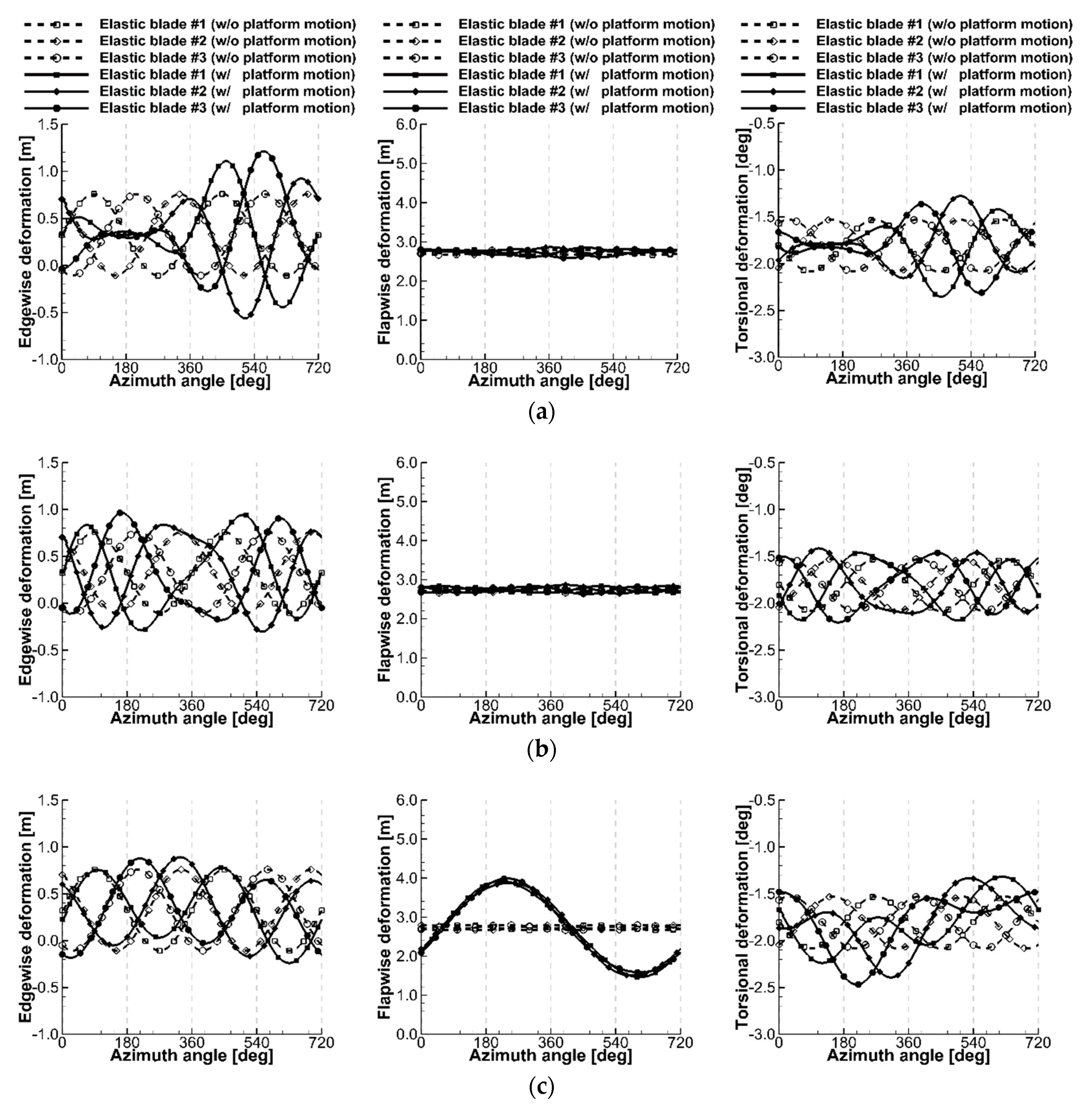
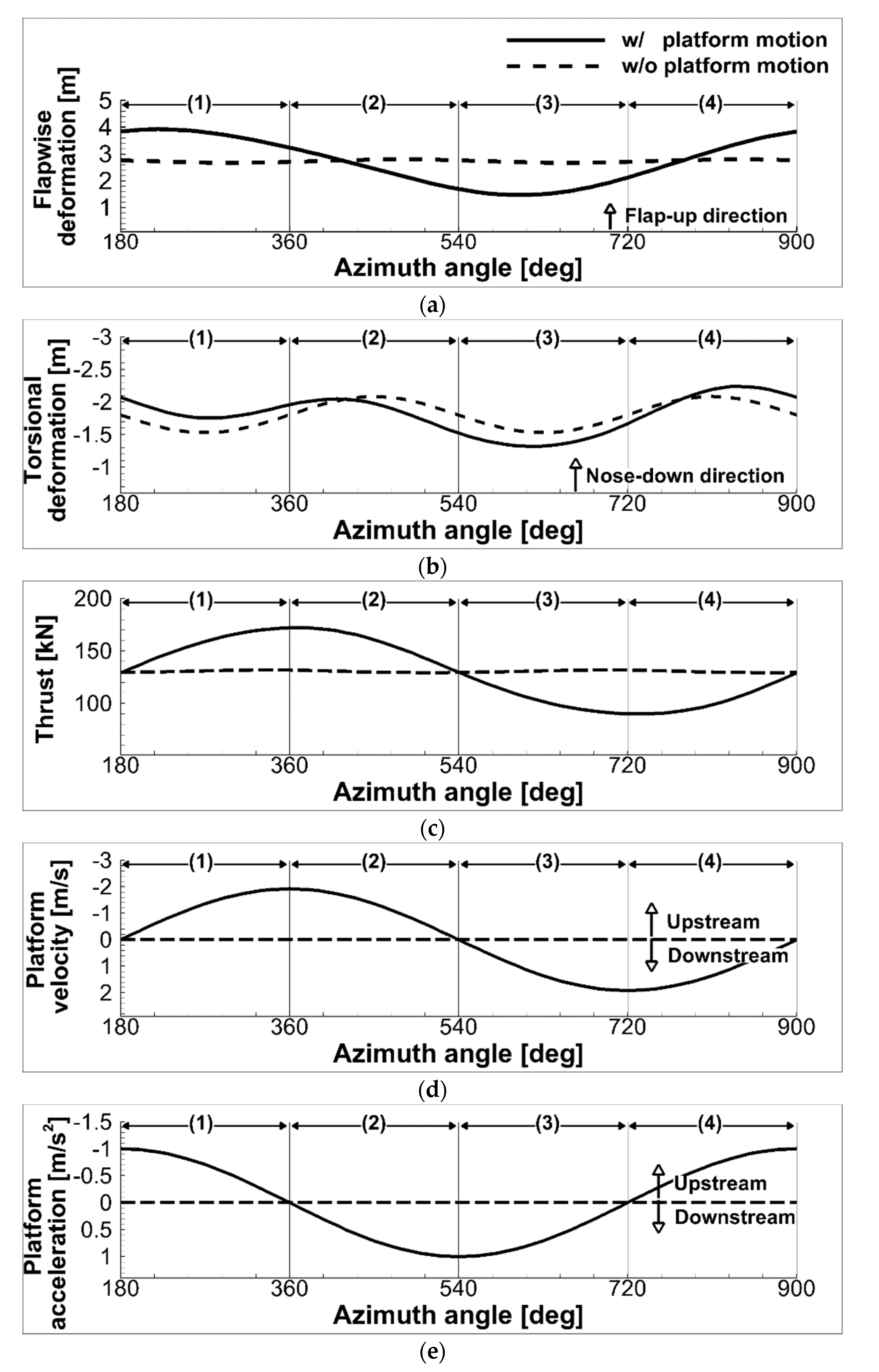
3.3. Aeroelastic Analyses of the Floating Offshore Wind Turbine

Lastly, the effects of platform motions on the aerodynamic performance and the aeroelastic behavior of the rotor blades of a floating offshore wind turbine were investigated. For this purpose, the calculations were made by considering the 6DoF platform motions, such as heave, sway, surge, roll, pitch, and yaw. The rotor blades of the wind turbine were assumed to be elastic bodies, but the flexibility of the tower and the rotor shaft was not considered in the present study. In Figure 7, the platform motions and the blade deformations are defined. The free-stream velocity was set to 8m/s, and the blades were assumed to rotate with a constant angular velocity of 9.15 RPM (0.96 rad/s). Additionally, the amplitudes of the translational and rotational platform motions were set to 4 m and two degrees, respectively, which are within the range that can approximately describe the practical operating conditions. For the convenience of the analyses, the frequency of the platform motion was set to 0.48 rad/s, which is one-half of the angular velocity of the turbine rotor, for both the translational and rotational platform motions. Thus, the rotor blades make two revolutions for one period of the platform motions.
In Figure 8, the effect of different time step size on the rotor power coefficient and the blade tip deformation is presented for one period of the platform surge motion. It is shown that, out of the four-time steps tested, the numerical solutions are fully converged and are almost identical when 5-degree and 10-degree time steps were used. In this regard, the time step size of 10 degrees, was adopted for all unsteady calculations in the present study.

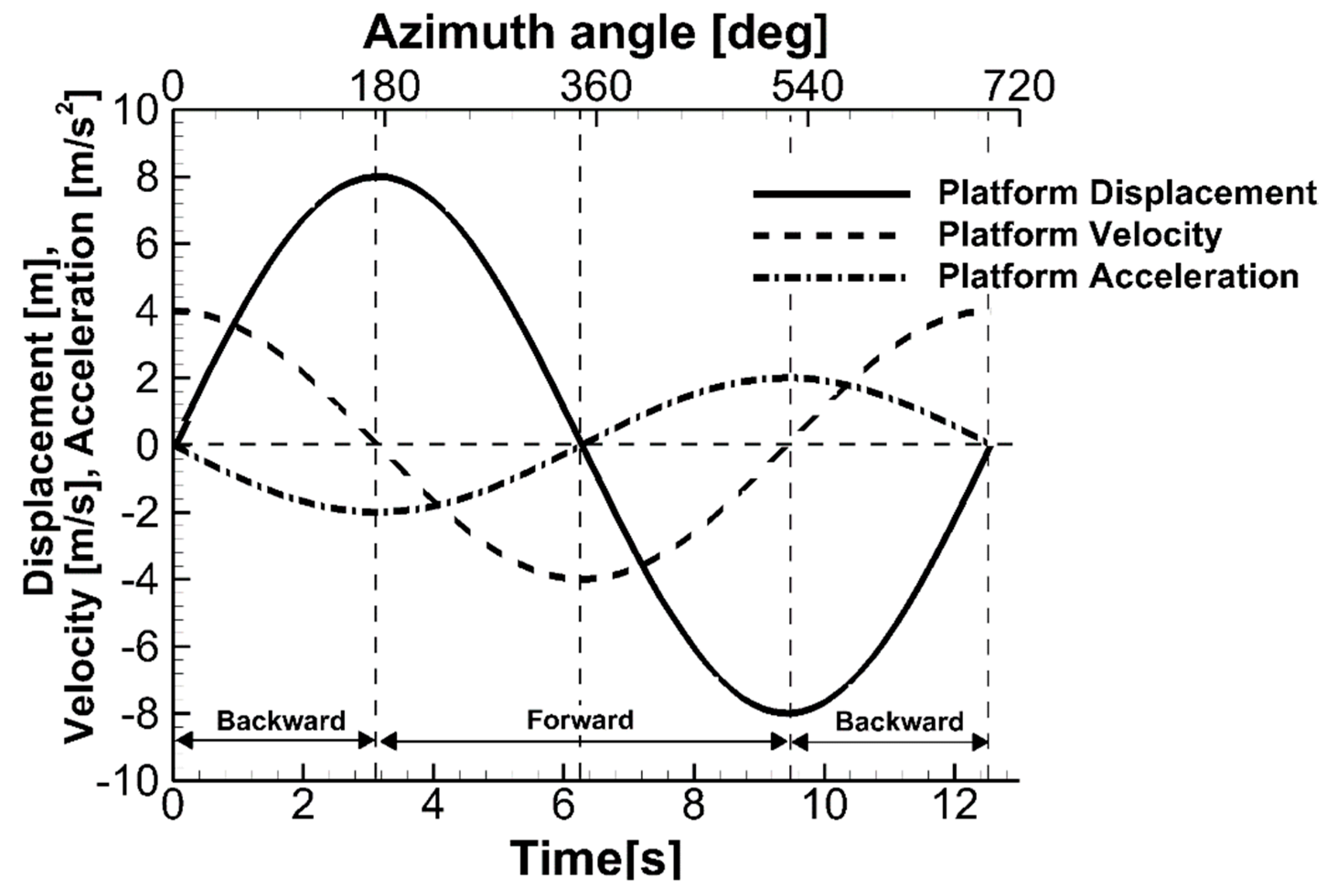
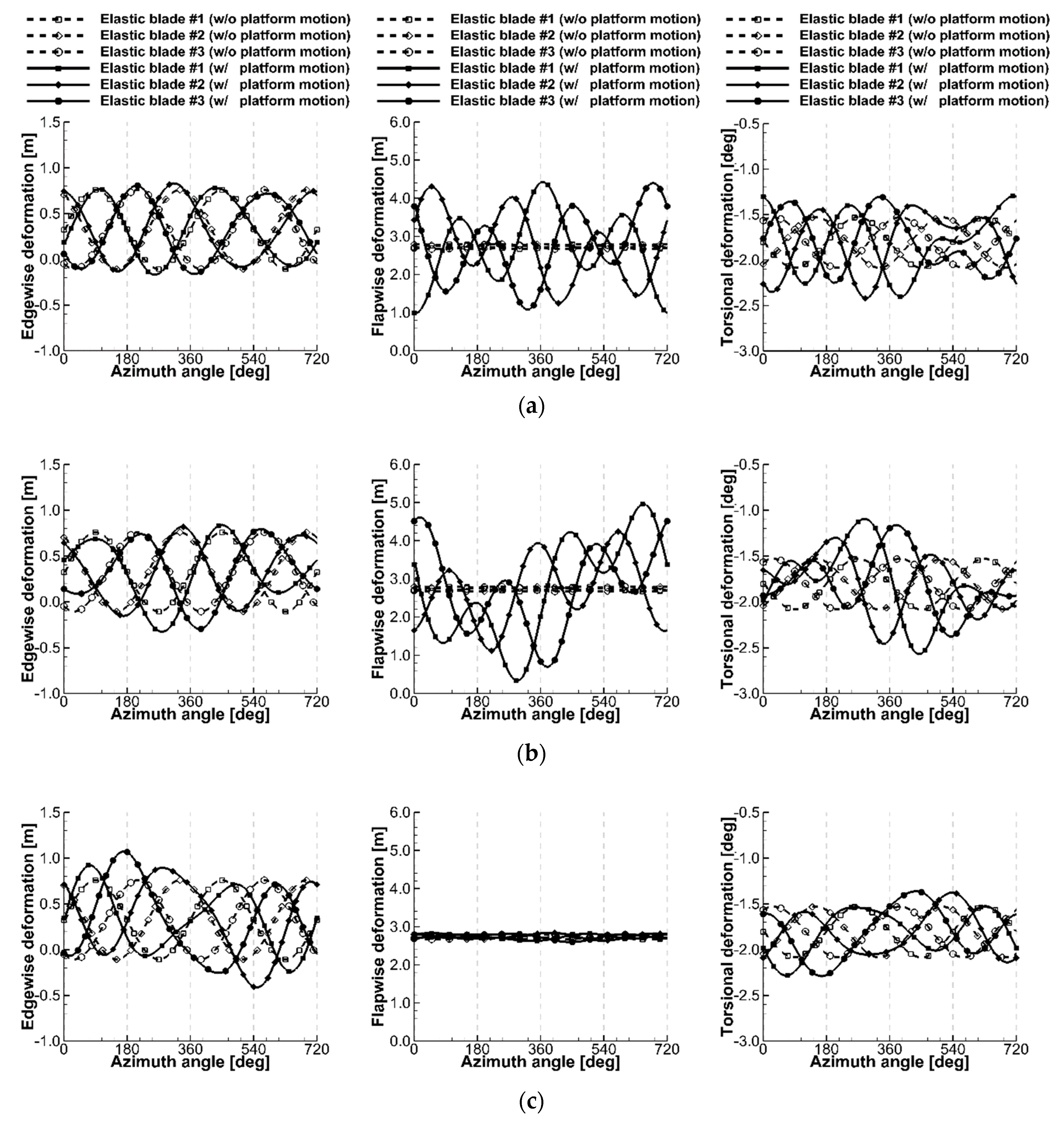
3.3.1. Consideration of Translational Platform Motions

At first, the calculations were conducted by considering the translational platform motions. In Figure 9, the thrust and power coefficients of the floating offshore wind turbine are compared between the rigid and elastic blades, along with those of a bottom-fixed wind turbine. It is shown that, when the blade elasticity is considered, the rotor thrust and power coefficients are reduced on average by about 5% and 1.5%, respectively, mainly due to the nose-down torsional deformation. Out of the three translational platform motions, the dominant influence on the aerodynamic loads appears by the surge motion, as shown in Figure 9c, because the upcoming normal velocity to the rotor is added to the free-stream by this oscillatory motion. The change of the relative velocity to the rotor significantly alters the blade effective angle-of-attack, and, thus, the aerodynamic loads are significantly affected. However, in the cases of the platform heave and sway motions, the change in the relative velocity occurs in a way that is mostly parallel to the rotor disk plane. Thus, the contribution of these in-plane rotor oscillations to the blade effective angle-of-attack and to the resultant aerodynamic loads are relatively small.
Figure 10 shows the edgewise (lead-lag), flapwise, and torsional deformations at the blade tip under the translational platform motions. In calculating the blade deformations, the aerodynamic loads, gravitational forces, and inertia forces due to the platform motions were simultaneously considered. It is shown that, in the case of the platform heave motion, the edgewise and torsional deformations occur most significantly. This is because the gravitational force and the blade inertia force due to the heave motion dominantly affect the edgewise deformation. This edgewise deformation also induces the torsional deformation by the non-linearity of the blade structure. Compared to the turbine without the platform motion, the peak-to-peak amplitudes of the edgewise and torsional deformations with the platform heave motion are smaller from zero to 360 degrees azimuth angles due to the downward platform acceleration, and become larger between 360 and 720 degrees by the upward acceleration. On the other hand, the flapwise deformation is not very noticeable for the heave motion because the aerodynamic load changes are not significant, as shown in Figure 9a.
The platform sway motion also causes the edgewise and torsional deformations shown in Figure 10b, since the inertia force is affected by the motion. However, the phase shift of the deformations is more dominantly observed than their magnitude changes.
In contrast, when the platform performs a surge motion, the flapwise deformation is dominantly affected, as shown in Figure 10c, because the blade normal force, and also the rotor thrust, significantly change. The positive and negative peaks of the flapwise deformation appear near the azimuth angles of 240° and 600°. Since the three blades experience identical relative velocities due to the surge motion, the flapwise deformations are in the same phase for all blades.
In addition to the aerodynamic loads, the inertia force of the blade caused by the platform motion also influences the blade deformations significantly. To investigate these effects more in detail, the correlation between the exciting forces and the resultant blade elastic deformations is examined for one period of the platform surge motion, as shown in Figure 11. At the beginning of this period, the wind turbine is assumed to be at the far downstream position with the reference blade aligned parallel to the turbine tower, and then starts to move forward toward its upstream direction. At this initial stage, the thrust becomes larger because the platform velocity increases. In addition, as the platform accelerates, the blade inertia force builds up in the downstream direction, which further increases the flap-up and nose-down torsional deformations. As a result, the clearance between the blade tip and the tower is reduced from 0.2 R to 0.135 R . When the turbine continues to move further upstream past the half way, the thrust starts to decrease as the platform upstream velocity is reduced. As the platform decelerates and now the blade inertia force acts toward the upstream, the magnitudes of the flapwise and torsional deformations are reduced, and eventually become smaller than those of the blade without the platform motion. When the turbine reaches the uppermost upstream and starts to move backward, the flap-up and nose-down torsional deformations continue to decrease and then eventually start to increase. During this stage, the thrust continues to decrease. When the turbine keeps moving and passes the half way, which decelerates to the downstream, the thrust again starts to increase. The flap-up and nose-down deformations continue to increase, and eventually become larger than those without the platform motion.
Figure 12 shows the blade root bending moments in the flapwise and edgewise directions when the platform is under the translational motions. The root bending moments are presented with respect to the undeformed frame, and are positive in the flap-down and lead directions of the blade, respectively. The flapwise bending moment is generally affected by the blade normal force associated with the thrust, and, therefore, its amplitude is most significantly affected by the platform surge motion, as shown in Figure 12c. When the elastic blade deformations are considered, the flapwise bending moments are reduced on average by about 8% compared to those of the rigid blade, mostly due to the effect of the nose-down torsional deformation. In the case of the edgewise bending moments, little difference is observed between the rigid and elastic blades. This is because the loads acting in the edgewise direction are mainly from the gravitational force. Consequently, the maximum and minimum edgewise root bending moments appear at the azimuth angles of 90° and 270° when the blade is aligned sidewise parallel to the ground.

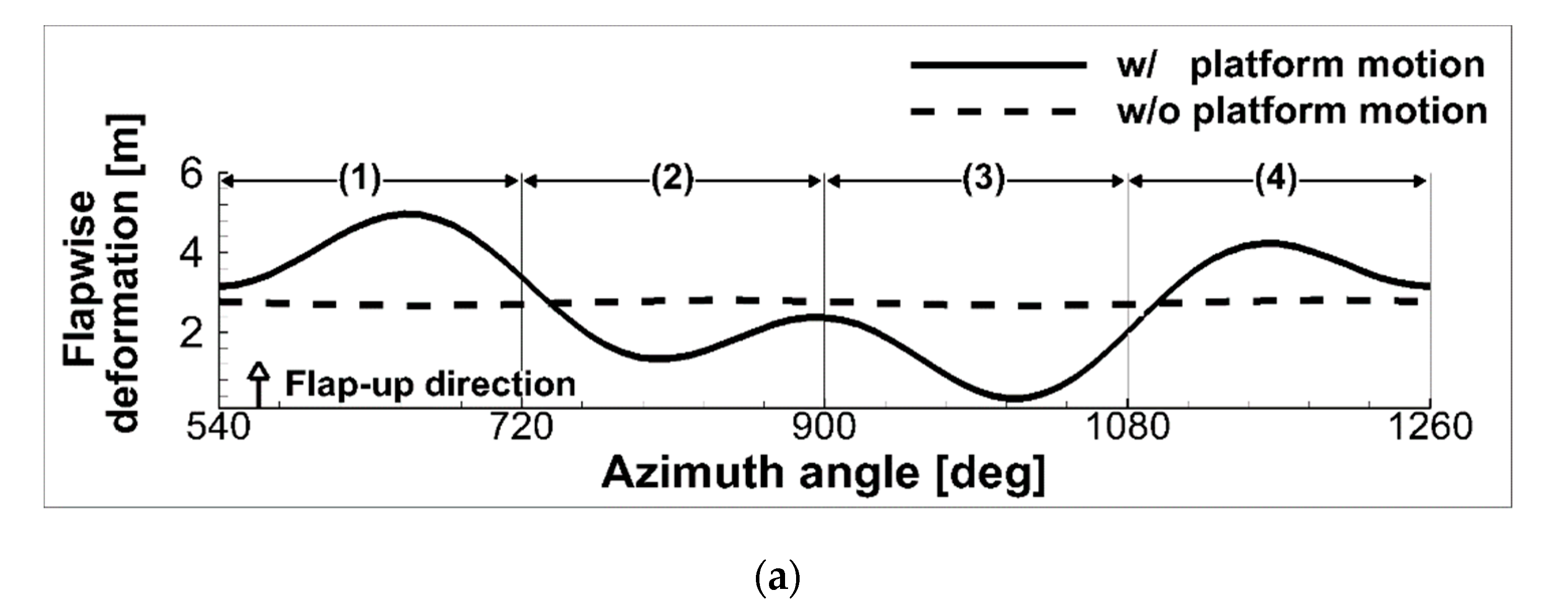
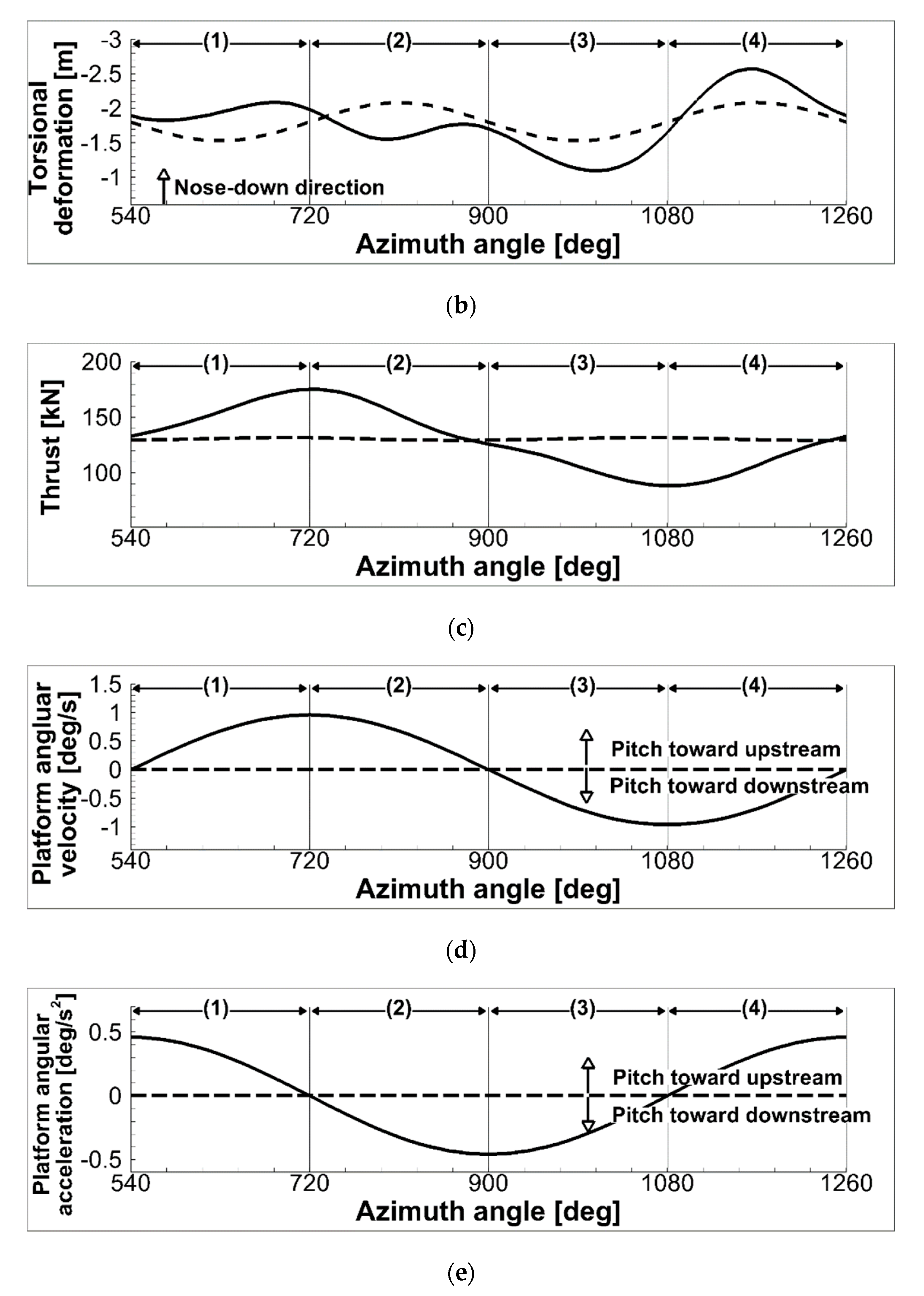
3.3.2. Consideration of Rotational Platform Motions

Next, the effects of the rotational platform motion on the aerodynamic performance and the aeroelastic behavior of the floating offshore wind turbine rotor blades were investigated. In the present study, the rotational center of the wind turbine was set at the bottom of the tower. In Figure 13, the thrust and power coefficients are presented for one period of the rotational platform motion. Figure 14 shows the corresponding blade tip deformations in the edgewise, flapwise, and torsional directions.
It is observed that, when the platform is in the yaw motion, the thrust and power coefficients remain unchanged, as shown in Figure 13a. However, the flapwise and torsional deformations are significantly changed, as shown in Figure 14a. Since the turbine rotates about the axis along the tower, the thrust and power on the blades increase in the advancing side, while those in the retreating side are reduced by a similar amount. Consequently, even though the thrust, power, and aeroelastic deformation show a time-varying behavior by each blade, the integrated sum for the whole rotor is preserved to be nearly constant.
When the platform is in its pitch motion, the aerodynamic loads vary considerably, as shown in Figure 13b. In addition, the flapwise and torsional blade deformations significantly change. For this platform pitch motion, the overall trend of the aerodynamic load variations is similar to those of the platform surge motion. However, the detailed behavior of the blade deformations is more complicated, because the relative velocity at each section of the blade differs depending on its azimuthal position. In addition, a phase difference exists between the blades in their flapwise deformations, because each blade is exposed to different relative velocities by the pitch motion.
To investigate the detailed effects of the platform motion on the blade deformations, the correlation between the exciting forces and the blade elastic deformations is examined for one period of the pitch motion, as shown in Figure 15. At the beginning of this period, the wind turbine is assumed to be at the downstream lay-back position where the reference blade is aligned in a parallel way to the turbine tower. When the turbine starts to pitch forward toward the upstream direction and starts to accelerate, the thrust becomes larger than the turbine without the platform motion. As the inertia force builds up, the blade flaps up further and the corresponding nose-down torsional deformation is also increased. When the turbine continues to rotate forward past the halfway upright position, the thrust is slowly decreased. Now as the turbine starts to decelerate, the flap-up and nose-down torsional deformations are reduced and become less than the turbine without the platform motion. When the turbine reaches the upstream droop position and starts to pitch backward, the thrust continues to decrease below the value without the platform motion. In addition, the inertia force by the platform angular acceleration now further reduces the blade flap-up and nose-down deformations. As the turbine continues to rotate further past the upright position and decelerates, the thrust starts to increase. The blade flap-up and nose-down torsional deformations continue to increase, and eventually the magnitudes become larger than those without the platform motion.
When the platform is in a roll motion, the whole turbine rotates, but the rotor itself is in a movement along the side-to-side direction with respect to the upcoming free-stream. Therefore, the overall behaviors of the aerodynamic loads and the blade deformations are mostly similar to the turbine in a translational sway motion. Thus, little changes in the thrust and power coefficients are observed, as shown in Figure 13c. The edgewise and torsional deformations are slightly affected by the platform roll motion, while the flapwise deformation remains relatively unchanged.
Figure 16 shows the blade root bending moments when the platform is in the rotational motions. It was observed that consideration of the elastic blade deformations results in a reduction of about 7% in the flapwise root bending moment on average, compared to that of a rigid blade. The flapwise root bending moment is mostly affected by the blade normal force, and the effect becomes particularly dominant in the case of the platform pitch motion. In the edgewise direction, the gravitational force is the main contributor, and, therefore, the root bending moments are not affected much by the platform rotational motions for both the rigid and elastic blades.

4. Conclusions

In the present study, a numerical methodology for predicting the aerodynamic performance and the aeroelastic behavior of floating offshore wind turbine rotor blades involving platform motions has been developed. The aerodynamic and structural analyses were carried out in a tightly coupled manner considering the transient flows caused by the platform motions. The structural model for predicting the elastic blade deformation is based on a nonlinear Euler-Bernoulli beam undergoing axial, lead-lag, flapwise, and torsional deformations. The blade element momentum theory was applied to calculate the aerodynamic loads on the rotor blades. Applications of the present method were made for the NREL 5 MW reference wind turbine under various operating conditions.
At first, the elastic deformations and the aerodynamic loads of bottom-fixed wind turbine rotor blades were calculated for various wind speeds. The results showed that the rotor blades experience fairly large elastic deformations, and the clearance between the tower and the blades can be reduced significantly due to the flapwise deformation. It was confirmed that consideration of blade elasticity is essential in the aerodynamic analyses of large-scale wind turbines. Next, the aerodynamic load variations of a floating offshore wind turbine under various platform sinusoidal surge motions were investigated. The rotor blades were assumed to be rigid bodies. The results were validated by comparing with other predictions by FAST and a CFD method. It was found that the rotor aerodynamic loads are significantly affected by the platform motion.
Lastly, the effects of platform motions on the aerodynamic performance and the aeroelastic behavior of a floating offshore wind turbine were investigated. The study was made for the cases when the platform is in sinusoidal oscillatory motions in each of three translational and three rotational directions. It was observed that flexible rotor blades exhibit complex vibratory behaviors under the various exciting loads, including the aerodynamic, inertia, and gravitational forces. In particular, the flapwise blade deformation is strongly affected by the aerodynamic force variation associated with the platform motion. The nose-down torsional blade deformation tends to reduce the aerodynamic loads. The flapwise root bending moment of the blade is also affected by the platform motions, especially in surge and pitch. In the edgewise direction, the gravitational force is the dominant factor to the root bending moment, while the effect of platform motions is minimal.
It was concluded that the present method is well-established, and is suitable for predicting aerodynamic loads and aeroelastic deformations of floating offshore wind turbine rotor blades involving platform motions.

Author Contributions

Investigation, Y.K.; Software, Y.K.; Writing – original draft, Y.K.; Writing - review & editing, Y.K. and O.J.K.; Supervision, O.J.K.;

Funding

The Korea Institute of Energy Technology Evaluation and Planning (KETEP) and the Ministry of Trade, Industry & Energy (MOTIE) of the Republic of Korea (No. 20168520021200) supported this work.

Conflicts of Interest

The authors declare no conflict of interest.

Abbreviations

The following abbreviations are used in this manuscript:
BEMBlade Element Momentum theory
CFDComputational Fluid Dynamics
CSDComputational Structural Dynamics
GDWGeneralized Dynamic Wake model
NRELNational Renewable Energy Laboratory
Nomenclature
C T Thrust coefficient, T h r u s t / ( 1 / 2 ρ V 2 A )
C P O Power coefficient, P o w e r / ( 1 / 2 ρ V 3 A )
D 0 Amplitude of platform motion
h r c Vertical distance between top of tower and rotational center of platform, m
h s Vertical distance between top of tower and end of rotor shaft, m
h t Tower height, m
L o h Overhang length, m
q Nodal displacement vector represented by 15 degrees of freedom
R Blade span, m
r H Position vector of hub center defined in the nacelle frame
r k Position vector of arbitrary point on deformed blade defined in the inertial frame
r k / H Position vector of arbitrary point on the deformed blade defined in the hub frame
r N Position vector of the bottom of nacelle defined in the tower frame
r P Position vector of the rotational center of the platform defined in the inertial frame
r T Position vector of the bottom of the tower defined in the tower frame
T T I Transformation matrix from the inertial frame to the tower frame
u , v , w Blade deformations in axial, edgewise (lead-lag), and flapwise directions, m
X , Y , Z Coordinate system defined at a rotating hub center (Rotating hub frame)
X H , Y H , Z H Coordinate system defined at a hub center (Hub frame)
X I , Y I , Z I Inertial coordinate system (Inertial frame)
X N , Y N , Z N Coordinate system defined at the bottom of nacelle (Nacelle frame)
X T , Y T , Z T Coordinate system defined at the bottom of the tower (Tower frame)
x , y , z Coordinate system defined at the undeformed blade (Undeformed frame)
x P , y P , z P Magnitudes of translational platform motion along with X I , Y I , and Z I axes, m
x ˙ P , y ˙ P , z ˙ P Velocities of translational platform motion along with X I , Y I , and Z I axes, m / s
x ¨ P , y ¨ P , z ¨ P Accelerations of translational platform motion along with X I , Y I , and Z I axes, m / s 2
α s Shaft tilt angle, deg
β p Blade pre-cone angle, deg
θ Built-in pre-twist of blade, deg
θ x , θ y , θ z Rotational angles of platform with respect to X I , Y I , and Z I axes, deg
θ ˙ x , θ ˙ y , θ ˙ z Angular velocities of platform with respect to X I , Y I , and Z I axes, deg / s
θ ˙ x , θ ˙ y , θ ˙ z Angular accelerations of platform with respect to X I , Y I , and Z I axes, deg / s 2
ξ , η , ζ Coordinate system defined at the deformed blade (Deformed frame)
ρ s Blade mass per unit volume, k g / m
ϕ Blade torsional deformation about deformed axis, deg
ψ Rotor azimuth angle, deg
Ω Angular velocity of the rotor, r a d / s
ω Frequency of the platform motion, r a d / s
Subscripts
b Blade
D Deformed frame
I Inertial frame
i Induced downwash
p Perpendicular direction
r Radial direction
T Tower frame
t Tangential direction
Free-stream
Superscripts
A Gravitational loads
g Aerodynamic loads

References

  1. WindEurope. Wind Energy in Europe: Scenarios for 2030; WindEurope: Brussels, Belgium, 2017; pp. 7–11. [Google Scholar]
  2. Ram, B.; Energetics, Inc. Energy from Offshore Wind; National Renewable Energy Laboratory: Golden, CO, USA, 2006; p. 3.
  3. de Vaal, J.B.; Hansen, M.O.L.; Moan, T. Effect of wind turbine surge motion on rotor thrust and induced velocity. Wind Energy 2014, 17, 105–121. [Google Scholar] [CrossRef]
  4. Tran, T.T.; Kim, D.H. The platform pitching motion of floating offshore wind turbine: A preliminary unsteady aerodynamic analysis. J. Wind Eng. Ind. Aerodyn. 2015, 142, 65–81. [Google Scholar] [CrossRef] [Green Version]
  5. Tran, T.T.; Kim, D.H.; Nguyen, B.H. Aerodynamic Interference Effect of Huge Wind Turbine Blades with Periodic Surge Motions Using Overset Grid-Based Computational Fluid Dynamics Approach. J. Sol. Energy Eng. 2015, 137, 061003. [Google Scholar] [CrossRef]
  6. Tran, T.T.; Kim, D.H. Fully coupled aero-hydrodynamic analysis of a semi-submersible FOWT using a dynamic fluid body interaction. Renew. Energy 2016, 92, 244–261. [Google Scholar] [CrossRef]
  7. Rodriguez, S.N.; Jaworski, J.W. Towards identifying aeroelastic mechanisms in near-wake instabilities of floating offshore wind turbines. J. Energy Resour. Technol. 2017, 139, 051203. [Google Scholar] [CrossRef]
  8. Jeong, M.-S.; Cha, M.-C.; Kim, S.-W.; Lee, I.; Kim, T. Effects of torsional degree of freedom, geometric nonlinearity, and gravity on aeroelastic behavior of large-scale horizontal axis wind turbine blades under varying wind speed conditions. J. Renew. Sustain. Energy 2014, 6, 023126. [Google Scholar] [CrossRef]
  9. Yu, D.O. Predicting wind turbine blade loads and aeroelastic response using a coupled CFD-CSD method. Renew. Energy 2014, 70, 184–196. [Google Scholar] [CrossRef]
  10. Hodges, D.W.; Dowell, E.H. Nonlinear Equations of Motion for the Elastic Bending and Torsion of Twisted Nonuniform Rotor Blades; National Aeronautics and Space Administration: Washington, DC, USA, 1974.
  11. Newmark, N.M. A Method of Computation for Structural Dynamics. J. Eng. Mech. Div. 1959, 85, 67–95. [Google Scholar]
  12. Leishman, J.G. Principles of Helicopter Aerodynamics, 2nd ed.; Cambridge University Press: New York, NY, USA, 2005; p. 826. [Google Scholar]
  13. Hansen, M.O.L. Aerodynamics of Wind Turbines, 2nd ed.; Earthscan Ltd.: London, UK, 2008; p. 181. [Google Scholar]
  14. Butterfield, S.; Jonkman, J.; Musial, W.; Scott, G. Definition of a 5-MW Reference Wind Turbine for Offshore System Development; National Renewable Energy Laboratory: Golden, CO, USA, 2006.
  15. Johnson, W. CAMRAD II: Comprehensive Analytical Model of Rotorcraft Aerodynamics and Dynamics, Volume III: Rotorcraft Theory; Johnson Aeronautics: Palo Alto, CA, USA, 1992; p. 145. [Google Scholar]
  16. Leishman, J.G. Modeling of Subsonic Unsteady Aerodynamics for Rotary Wind Applications. J. Am. Helicopter Soc. 1998, 35, 29–38. [Google Scholar] [CrossRef]
  17. Leishman, J.G. Validation of Approximate Indicial Aerodynamics Functions for Two-Dimensional Subsonic Flow. J. Aircr. 1988, 25, 914–922. [Google Scholar] [CrossRef]
  18. Moriarty, P.J.; Hansen, A.C. AeroDyn Theory Manual; National Renewable Energy Laboratory: Golden, CO, USA, 2005.
Figure 1. Coordinate systems and blade deformation kinematics. (a) Coordinate systems of floating offshore wind turbine. (b) Blade deformation kinematics (Reproduced from [9], Elsevier: 2014).
Energies 12 02519 g001aEnergies 12 02519 g001b
Figure 2. Flow diagram of aeroelastic analysis for floating offshore wind turbine rotor blades.
Energies 12 02519 g002
Figure 3. Rotor aerodynamic loads and blade tip deformations of bottom-fixed wind turbine with varying wind speed. (a) Rotor aerodynamic loads. (b) Blade tip deformations.
Energies 12 02519 g003
Figure 4. Variations of displacement, velocity, and acceleration of the platform in surge motion ( D 0 = 8 m, ω = 0.500 rad/s).
Energies 12 02519 g004
Figure 5. Comparison of rotor thrust coefficient with other numerical predictions. (a) Case 1, (b) Case 2, (c) Case 3, and (d) Case 4.
Energies 12 02519 g005
Figure 6. Comparison of rotor power coefficient with other numerical predictions. (a) Case 1, (b) Case 2, (c) Case 3, and (d) Case 4.
Energies 12 02519 g006
Figure 7. Definition of platform motions and blade deformations.
Energies 12 02519 g007
Figure 8. Effect of time step size on the rotor power coefficient and blade tip deformation for one period of platform surge motion. (a) Rotor power coefficient. (b) Flapwise tip deformation.
Energies 12 02519 g008aEnergies 12 02519 g008b
Figure 9. Rotor thrust and power coefficients under translational platform motions. (a) Heave motion. (b) Sway motion. (c) Surge motion.
Energies 12 02519 g009aEnergies 12 02519 g009b
Figure 10. Blade tip deformations under translational platform motions. (a) Heave motion. (b) Sway motion. (c) Surge motion.
Energies 12 02519 g010
Figure 11. Blade aerodynamic loads and aeroelastic responses for one period of platform surge motion. (a) Flapwise deformation at the blade tip. (b) Torsional deformation at the blade tip. (c) Thrust force of the reference blade. (d) Velocity of the platform in surge motion. (e) Acceleration of the platform in surge motion.
Energies 12 02519 g011
Figure 12. Blade root bending moments under translational platform motions. (a) Heave motion. (b) Sway motion. (c) Surge motion.
Energies 12 02519 g012
Figure 13. Rotor aerodynamic loads under rotational platform motions. (a) Yaw motion. (b) Pitch motion. (c) Roll motion.
Energies 12 02519 g013
Figure 14. Blade tip deformations under rotational platform motions. (a) Yaw motion. (b) Pitch motion. (c) Roll motion.
Energies 12 02519 g014
Figure 15. Blade aerodynamic loads and aeroelastic responses for one period of platform pitch motion. (a) Flapwise deformation at the blade tip. (b) Torsional deformation at the blade tip. (c) Thrust force of the reference blade. (d) Angular velocity of the platform in pitch motion. (e) Angular acceleration of the platform in pitch motion.
Energies 12 02519 g015aEnergies 12 02519 g015b
Figure 16. Blade root bending moments under rotational platform motions. (a) Yaw motion. (b) Pitch motion. (c) Roll motion.
Energies 12 02519 g016
Table 1. Gross properties of NREL 5 MW reference wind turbine (Reproduced from [14], NREL: 2006).
Rating5 MW
Rotor configurationUpwind, three blades
Rotor, Hub diameters126 m, 3 m
Tower length ( h t )87.6 m
Overhang length ( L o h )5 m
Shaft tilt angle ( α s )
Pre-cone angle ( β p )2.5˚
Table 2. Amplitudes and frequencies of various platform motions.
Case 1Case 2Case 3Case 4
Amplitude ( D 0 )8 m8 m8 m8 m
Frequency ( ω )0.127 rad/s0.246 rad/s0.500 rad/s0.770 rad/s

