1. Introduction
Floor-cleaning robots have evolved from manual operation to autonomous over the past twenty years. As the world transforms to more developed conditions, the demand for cleaning robots, especially floor-cleaning robots, has steeply risen, which provides an opportunity for developing more advanced floor-cleaning robots. More than two decades ago, many large companies worldwide had started developing mobile robot systems for floor-cleaning services. Now, technology has attained a state that makes the mass production of these floor-cleaning robots possible. Floor-cleaning robots have evolved in various fields including industry, domestic and healthcare over the past fifteen years [
1]. Overall, the floor-cleaning robot market is expected to grow from USD 1.83 billion in 2017 to USD 4.34 billion by 2023, at a rate of 16.21 percent between 2018 and 2023 [
2]. Numerous studies are being conducted into different aspects of floor-cleaning robots such as mechanism, control, sensor systems, and autonomy. Such research led to the development of many advanced autonomous floor-cleaning robots incluidng Neato XV-11, Samsung Powerbot, Bobsweep Bobi, Miele Scout, iRoomba, and Infinuvo CleanMate. These are mainly designed for vacuuming and mopping floors in domestic settings. They are more convenient to use because they are less noisy to operate, require less storage space, and have an autonomous mode of operation. The performance of these robots can be enhanced with respect to the paths they follow in the work-space, the area of coverage, dealing with obstacles, clearing pet and human hair, and cleaning different floor types. Among these, area coverage is the major factor to determine the performance and efficiency of existing cleaning robots. Area coverage primarily depends on the shape and path-planning algorithm implemented in the robot.
Cleaning robots usually follow a coverage path-planning (CPP) algorithm to determine the path that covers a given area while avoiding the static or dynamic obstacles. This process can be applied to many types of robotic applications, like vacuum cleaning robots [
3], painter robots [
4], autonomous underwater vehicles [
5], demining robots [
6,
7,
8], lawn mowers [
9,
10], automated harvesters [
11,
12], window cleaners [
13], and inspection of underwater structures [
14]. Coverage algorithms can be independently classified into online and offline [
15]. Online algorithms (sensor-based algorithms) use appropriate real-time sensor to cover the given area. Offline algorithms depend on the predefined information about the environment that might be unreliable in many scenarios. In particular scenarios, a valid approach is to randomize the coverage path plan to achieve efficient area coverage. CPP algorithms usually divide the area (i.e., considering obstacle-free) into simple, non-overlapping regions called cells, each of which can be covered using zigzag motions generated by the algorithm, which is well documented in the literature [
16,
17,
18]. In addition, the author describes a novel approach for effective autonomous path planning that creates a new dynamic map to update the path-planning strategy when its predefined path is disturbed by a dynamic obstacle [
19]. A serpentine path pattern is achieved by an automatic path planner with the appropriate concatenation of more than five basic macros. Platform updates its internal geometric representation in case of dynamic obstacles and then replans its path to follow up on the leftover areas due to dynamic or temporary obstacles [
20]. Another approach outlines the complete coverage navigation of a floor-cleaning robot with the entire coverage floor-cleaning strategy and executes back-and-forth floor-cleaning tasks. The infrared sensors help the robot to stay aligned in the planned path, avoiding walls and obstacles [
21].
The existing floor-cleaning robots have either a fixed circular or D-shaped morphology. The performance loss of these robots is mainly due to their fixed morphology, which constrains them from reaching room corners, regions around circular pillars, and narrow spaces between furniture and artefacts in a fixed environment. The size and shape of the cleaning area vary in the real-time dynamic environment. One primary factor that curtails the robots’ performance in area coverage is their shape, which restricts their navigation when they are accessing narrow spaces. One viable or alternative design strategy to overcome these bottlenecks in area coverage of the cleaning robots is to design next-generation robotic platforms with self-reconfigurable mechanisms. In the process of developing an area coverage robot, it is critical to address its ability to demonstrate the navigation energy during coverage. So far, numerous coverage path-planning techniques have been proposed and implemented successfully. However, such an algorithm was mostly realised in the fixed morphological platforms. When it comes to reconfigurable robotic systems, due to their ability to form morphologies, we require novel coverage path-planning approaches that could direct the different morphological forms of the robot. To enhance cleaning performance in dynamic environments, there is a need to consider the morphology of the cleaning robot when designing a cleaning platform. Considering these aspects, our team has implemented the concept of self-reconfiguration in floor-cleaning robots and built hTetro and hTetrakis platform [
22,
23,
24]. These self-reconfigurable floor cleaning robots include tiling based area coverage path planning algorithms which are inspired by the Tetris game. Our team has extensively studied the cleaning capability and coverage path planning of this class of robots. The path-planning technique is based on the combinatorial properties of tetrominoes and polyforms [
22,
25]. The hTetro platform consists of four rectangular blocks connected by mechanical hinges. It applies the theory of hinged dissection of polyominoes and undergoes seven different morphologies. This platform is able to navigate through a real-time indoor environment and to clean the floor based on polyomino tiling theorems. Another platform, hTetrakis, is made up of three triangular blocks that attains three different morphologies based on a polyiamond-based tiling concept and can cover narrow and convex corners. These robots could generate a global tileset for the deployed region and perform coverage by navigating on the generated tiles while assuming its morphology on each tile piece. These platforms have straight edges that skip the curved and circular areas in the cleaning space. To enhance the cleaning capability in dynamic environment and curved work-space, a polyhex-based reconfigurable robot, hHoneycomb, is developed which includes polyhex-tiling theorems for area coverage.
Polyhex tiling theories based on mathematical concepts have been studied and implemented in graphics and gaming applications. Due to the higher order symmetry of the polyhex, it is widely used in recreational mathematics. However, polyhex tiling theories have not been applied in robotics. This is the first attempt to apply polyhex tiling as a coverage path-planning technique in a self-reconfigurable floor cleaning robot. The fundamental unit of hHoneycomb platform is a regular hexagon. Hexagonal shapes are usually preferred to square or triangular shapes in nature, engineering and architecture because they are more stable and cover the space in an efficient way, requiring the least boundary length compared with triangles or squares of the same area. Other advantages of a hexagonal shape are that it has six rotational symmetries (rotational symmetry of order six), six reflection symmetries (six lines of symmetry), and the number of lines of symmetry is equal to the number of sides. Due to its special geometric features, it can produce symmetric shapes when hexagons are put together along their edges. This platform is made up of four regular hexagonal blocks that are connected via mechanical hinges at the vertices. All blocks are designed to accommodate sweeping, vacuuming, and other cleaning modules inside it. By altering the alignment of each hexagonal unit about its mechanical hinge, the platform is able to form six morphologies, all of which have unique structural forms that help access the cleaning area.
Reconfiguration and mobility are two important properties of the self-reconfigurable floor-cleaning robots. The cleaning capacity of this platform entirely depends on the manoeuvrability of the platform. It means that wheel skidding and slipping during locomotion limit the trajectory locomotion performance of the platform. In the absence of the correct manoeuvrability, the platform will either skip or recover a few regions of the cleaning area. In such circumstances, it is not feasible for the robot platform to follow tiling-based path-planning techniques. During reconfiguration, the transfer of mechanical forces and moments, electrical power and communication among various blocks are the major tasks. In addition, the design of structural platform and control architecture plays a critical role in forming various morphologies. The synchronous operation of each morphology is challenging because each block of the platform consumes different amounts of energy. Proper utilization of navigation energy is another key aspect for enhancing the performance of the floor-cleaning robot. It is because the pay load, task execution, operation, and locomotion of the platform regulate the current, torque, and power utilisation [
26,
27] of the motors. Thus, motor’s power ratings needs to be analysed before real-time deployment. To address these issues, a detailed study of the current requirement of the hinged motor is conducted.
This paper describes a novel self-reconfigurable floor cleaning platform, called hHoneycomb which follows planar polyhex-based path-planning techniques. The remainder of the paper is organised as follows.
Section 2 briefly describes the combinatorial properties of a polyhex.
Section 3,
Section 4,
Section 5 and
Section 6 describe the robot architecture, structural design and analysis, platform’s kinematics during locomotion, and platform’s dynamics during reconfiguration, respectively.
Section 7 and
Section 8 describe polyhex based path-planning techniques and navigation energy obtained from the experiments respectively.
3. Robot Architecture
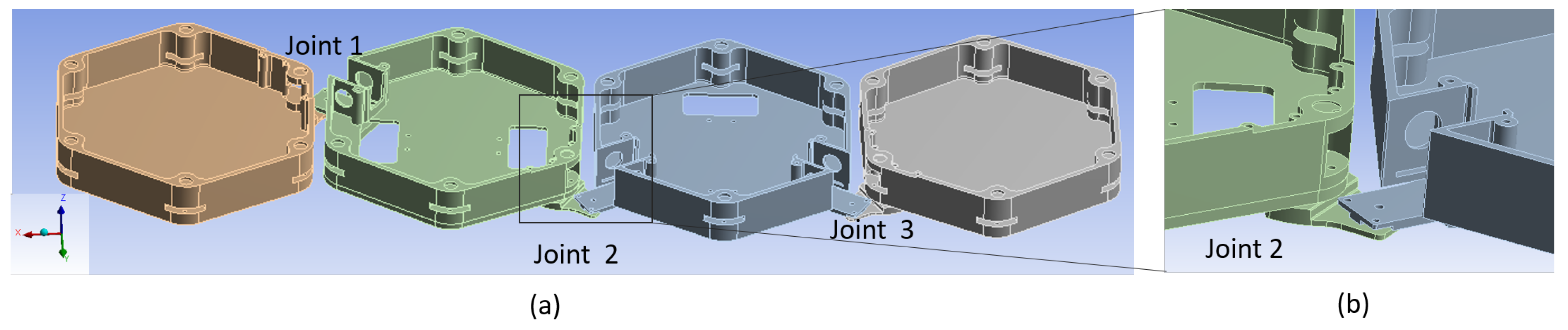
The hHoneycomb robot consists of four hexagonal blocks, each of which undergoes rotational movement and the platform attains multiple configurations. To have a relative planar motion among two blocks, the blocks can be connected by a mechanical hinge with the joint axis perpendicular to
plane. To obtain multiple configurations during shape-shifting, the hinges can be placed either at joint location 1, 2 and 3 along the top edge, at 4, 5 and 6 along the bottom edge or a combination of both, shown in
Figure 2a. By keeping the revolute joints at 1, 2, and 3, five distinct configurations (bar, bee, pistol, worm, and arch) are obtained as shown in
Figure 2b. However, by keeping the revolute joints at 4, 5, and 6, six distinct configurations (bar, bee, pistol, worm, arch and wave) are obtained as shown in
Figure 2c.
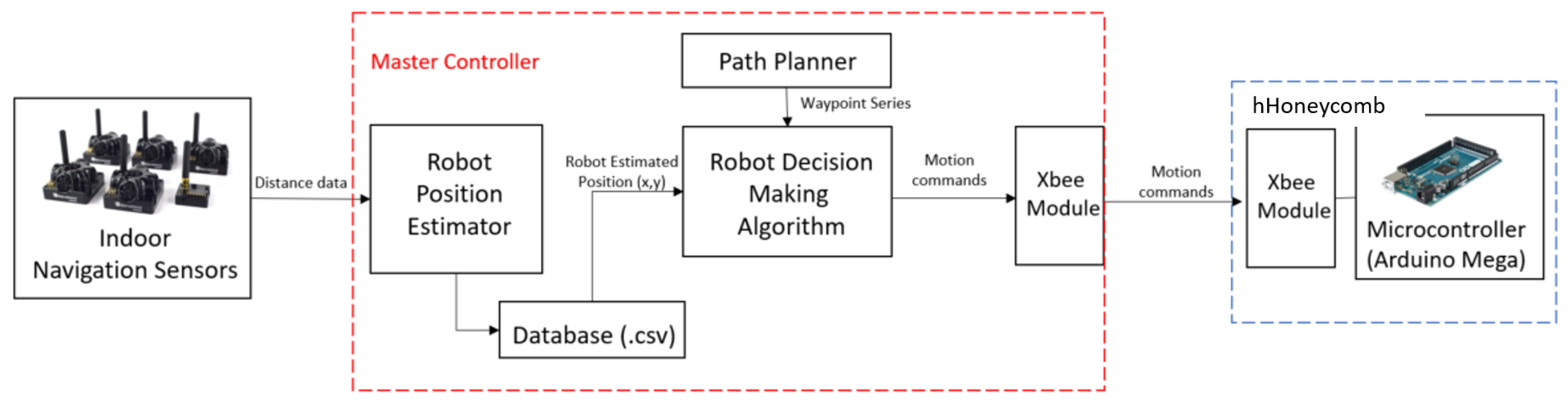
hHoneycomb robot operation is based on an ultra-wideband (UWB)-based radio navigation system. This system has the distance and location accuracy of 5–10 cm with significant low-power Wi-Fi and BLE (Bluetooth Low Energy). These features of UWB navigation make the platform suitable for real-time monitoring of hHoneycomb robot. The robot is controlled using an Atmega 2560 16-bit microcontroller through full-duplex serial communication. The block diagram of the electronics module and the communication architecture diagram of of the platform are shown in
Figure 3 and
Figure 4, respectively. The communication module consists of an upper layer of autonomy and a lower layer of locomotion control. The autonomy layer, running on an Intel Compute Stick, creates a map of the environment using LIDAR. In the map, the path is generated together with required configurations. Moreover, the autonomy layer, upon executing the main algorithm, extracts data of position coordinate, i.e., (x,y) and orientation from LIDAR and commands the microcontroller to perform required locomotion such as forward, backward, left, right, and orientation correction. Through the microcontroller located in module 2, the locomotion layer, using the kinematic model, calculates individual wheel velocities. Each wheel angle extracted from the absolute encoder is fed back to the microcontroller, which then regulates the locomotion error and, through the serial communication, outputs the required velocities of the platform using Proportional-Integral-Differential (PID) control. The velocities are executed and regulated individually in a RoboClaw motor controller of each module.
The navigation of the robot is based on waypoints generated by an offline global path-planning algorithm. Each waypoint contains the information of the desire position with a specific configuration that the robot should achieve. The robot follows the linear motion command from the master controller to perform the navigation process and shape-shifting. In order to have better efficiency in cleaning, whenever the robot reaches the waypoint within a certain threshold, the waypoint will be marked as covered. On the other hand, the robot is also controllable through a Bluetooth communication interface by the user. The command will be received by Arduino and passed to the motor controller unit.
The control architecture of hHoneycomb is comprised of path planner and motion planner modules. The path planner generates a sequence of waypoints as the output on the environmental map. Each waypoint stores the information about the platform coordinates and the corresponding configurations. The motion planner helps the platform traverse between two consecutive waypoints. It prioritises the shape-shifting before it proceeds to the motion process. The motion planner sets the tilling patterns and the trajectory based on the environment. The shape-shifting and locomotion units are independent. Shape-shifting and locomotion are performed by servo motors and DC motors, respectively. Hence, the motion planner consists of a master control system with two layers, i.e., one low-level controller to control the platform velocity and another high-level controller to control the heading angle. Both layers incorporate a PID controller, with the angular position feedback obtained from the encoders.
Based on the joint layout described above, the mechanical design of the hHoneycomb platform is obtained. Each block of the platform is a hexagonal prism of side 140 mm and height 50 mm. The block of the platform, motor housing, and hinged joint component are fabricated with polylactic acid (PLA) material using a Cubicon 3D printer. The bar, bee, wave, pistol, and arch configurations of the robot structure are shown in
Figure 5. These blocks accommodate all the cleaning accessories, the electronic hardware components, motors and wheels. The blocks are kept at sufficient distance to achieve collision-free motion of each connecting block during shape-shifting. The platform consists of a structural, hinged joint, locomotion, motion controller, and navigation modules. For motor’s speed of 30 rpm, the maximum translational speed of the platform is approximately 90 mm/s. Considering the robot attains this maximum speed in 3 s on flat terrain, the acceleration of the platform is approximated as 30 mm/s
. For 2.5 kg platform’s weight including the mechanical, electronics and cleaning modules, the torque required by the wheel’s motor is 1.8 Nmm. Hence, a motor with torque capacity, higher than the total torque needed to drive the load, is required for this platform. A plastic-geared DC motor (Gear ratio of 200:1) with a voltage rating of 6 V, a rotational speed as 51 rpm, and a maximum torque of 706 Nmm is selected. The omnidirectional wheels (plastic, 58 mm diameter, maximum 50 rpm) are mounted with the plastic-geared DC motor (90-degree output, with a gear ratio of 200:1). Herkulex drs 0201 servo motors with a voltage rating of 7.4 V and a stall torque of 24 kgcm are mounted at the hinges to rotate the blocks during reconfiguration. A 7.4 Volt Lipo battery is used as the external power supply for this platform.
5. Platform’s Kinematics during Locomotion
In hHoneycomb platform, block 2 is mounted on two omni-wheels with spinning axes along
X-direction. Block 3 is mounted on other omni-wheels with spinning axes along
Y-direction. The other two blocks are mounted on castor wheels for stability during locomotion and shape-shifting. The platform and each block have three degrees of freedom (translation and rotation on
plane). The wheel layout is shown in
Figure 8, and the kinematic relationship between the velocity of each wheel and the translational and rotational velocity of the platform are discussed below.
Two coordinate frames, i.e., global (
) and robot reference (
) frames are attached the bar configuration of platform. The global reference frame is located at the centroid of the robot under an bar shape with the positive
X direction orthogonal to the wheels in block 2, shown in
Figure 8a. The location of the origin of the robot reference frame is at the centroid of any configuration, which can be denoted as
and
with respect to the global frame. The values of
,
, and
of the bar and arch configurations are shown in
Figure 8b,c respectively. The positive
x direction of the robot reference frame is defined as half of the rotation angle of the middle joint, which is denoted as
. As the platform undergoes shape-shifting and attains one of the six forms, the location of the centriod varies with respect to each form. The kinematic model of the robot was formulated in the robot reference frame.
, and
are the velocities of the wheels along the positive direction of each wheel as shown in
Figure 8a.
are the constant normal distance from the centroid to the
plane of each wheel that can be expressed as Equation (
1). Thus, the velocities of the platform can be expressed using the parameters in Equation (
2). The equations are rearranged into matrix form as given by Equation (
3).
5.1. Optimization
As shown in this system, with a unique set of platform velocity
and
, there are infinite sets of wheel velocities
and
. The objective is to choose the set of wheel velocities to maximize the platform speed on either
x-axis,
y-axis or about
z-axis while restricting the speed of the motor. For instance, when travelling along
x-axis, the objective function
is to be maximized while restricting
to zero and
to zero. The third constraint is to limit the speed of the motor with respect to the hardware limitation of the motor. Thus, an optimisation was done to maximise the component along the desired axis while limiting the other two components to zero. The optimisation of
is formulated as given by Equation (
4). The robot system only makes use two conditions where
equals to either 0 or
. The results of the optimization under these two situations are listed in the
Table 1. The first row of the
Table 1 is when the heading direction is set to be on
x-axis. In bar configuration, since the robot is symmetric about
x-axis,
and
can be directly set to zero. For arc configuration, all four motors need be activated in order to eliminate the motion along
y-axis and pivot-turning. The same situation happens when moving in
y direction where all four motors need to be activated to regulate the motion only on
y-axis. The result ensures the maximum velocity on the desired direction and zero velocities along the other two directions.
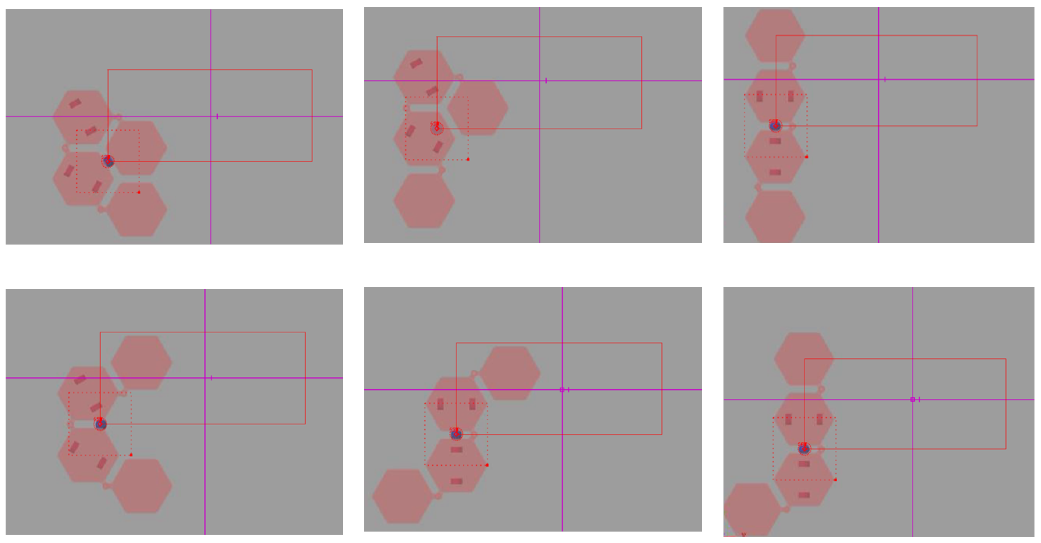
5.2. Simulation
Simscape multibody toolbox in Matlab was used to simulate the locomotion performance of the hHoneycomb platform. Four hexagonal blocks of the platform were modelled as rigid bodies connected by passive revolute joints. The middle blocks are mounted on two omnidirectional wheels. To simulate the omni-wheels, the connection between them and the body are considered as actuated revolute joints, while the connection between wheels and grounds were passive planner joints. Kinematics of omnidirectional wheels discussed in the previous section were used to estimate the translational and rotational motion of the platform. The mechanical system was simulated using rigid bodies with revolute joints. Simscape Multibody Contact Forces Library was used to model the contact between the wheels and the ground. After that, the rpm of the motor was set as input for the model, and the velocity of the body was output to the Matlab work-space.
Table 2 shows the result from the simulation model.
Figure 9 shows the mobility of the different configurations of the platform in the Simscape environment.
As listed, the required input sets are different for the x and y locomotion due to the difference of value, while for pivot turn, the required input set is the same. The reason is the difference in the wheel position. When , it is apparent that x locomotion is only affected by the motors 1 and 2 and the y locomotion is only affected by the motors 3 and 4. However, due to the position of the centroid, to restrict the rotation motion during the y locomotion, motors 1 and 2 should also be activated and provide the opposite angular velocity compared to that generated by the motors 3 and 4. When , the situation is more complicated because the relative direction of the wheels and the axis changed. Therefore, to move the robot in x or y direction, the motors located outside should be activated at full speed to provide the motion in the desired direction, and the motors located inside should be activated accordingly to restrict the rotation motion. Moreover, the velocity of the wheels under the two cases cannot be linked by a transformation matrix. In other words, although the coordinates can be mapped using the transformation matrix, the velocities are still independent on each other due to the change of centroid that results in the different contribution to the rotation motion.
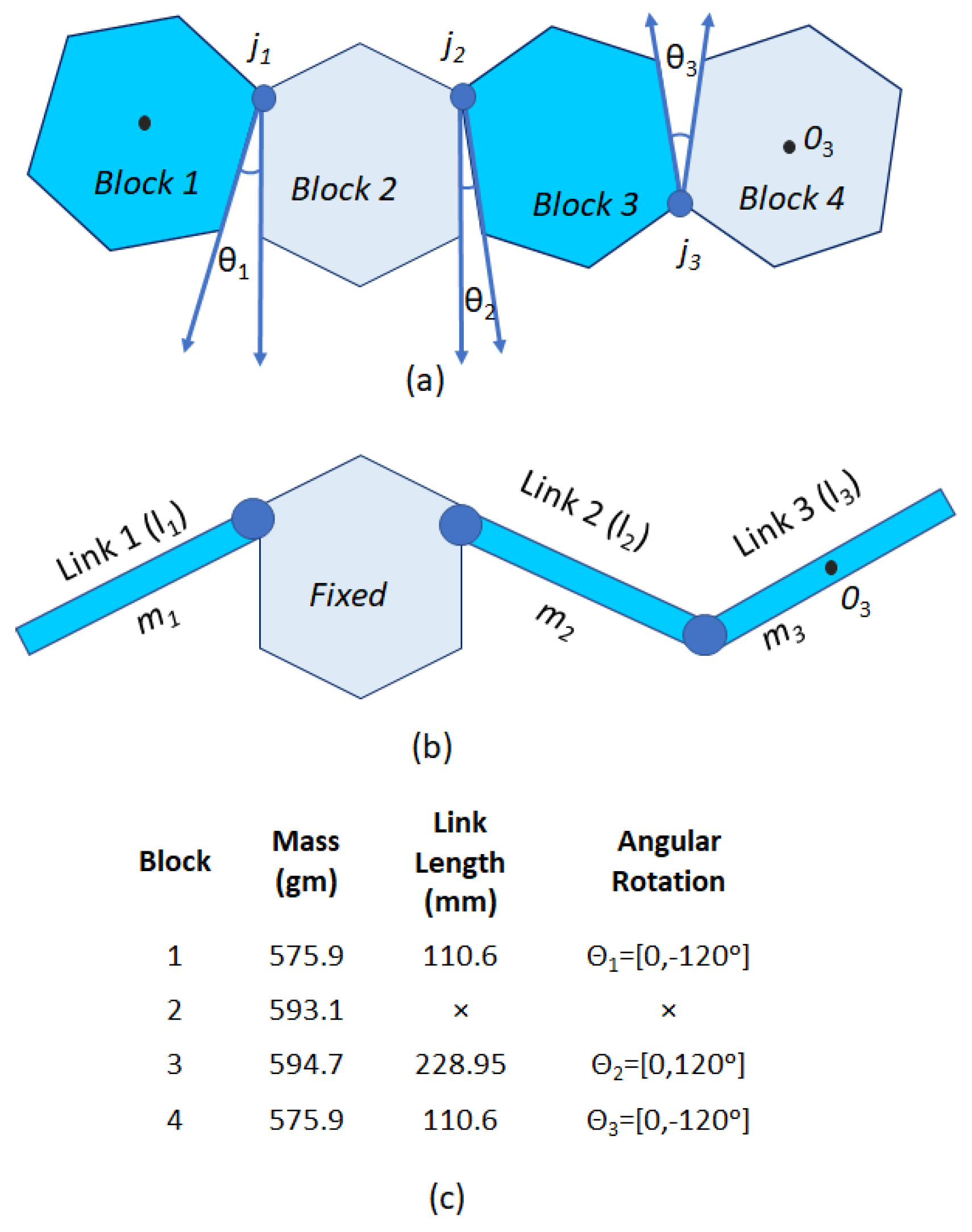
6. Platform’s Dynamics during Reconfiguration
The dynamics of the platform during the shape-shifting process is discussed below. Rotation of each block about the nearest hinge joint generates a new configuration. While achieving all six shapes of hHoneycomb, the block 2 remains stationary (does not rotate). The rotation of the block 1 with respect to the joint 1 (
) is represented as a single link manipulator. Both blocks 3 and 4 are presented as serial double links with respect to the joint 2 (
). Blocks 1, 3, and 4 are considered as links 1, 2, and 3, respectively.
,
, and
are the effective lengths of links 1, 2, and 3, respectively. Let
,
, and
are the rotation of the links
and 3 about the joints
,
, and
, respectively, as shown in
Figure 10a–c. These three angular rotations represent the generalised coordinates of the platform. As each link has distributed mass, the moment of inertia of these links are considered in the formulation of kinetic energy. We consider all the blocks as rigid bodies. During reconfiguration, the velocity of all the blocks of any form remains the same and is independent of various forms generated during the reconfiguration process. The robot moves on the flat terrain and the gravitational potential energy is constant. Hence, the change in potential energy is zero, and the Lagrangian function
is only due to the total kinetic energy of the links. The total kinetic energy
of the platform during shape-shifting is the sum of the kinetic energy of all links. Let
,
,
be the kinetic energy of the links 1, 2, and 3, respectively. Links 1 and 2 are rotating about the fixed point (
and
, respectively. However, link 3 is rotating about the centre of mass (
). Let
and
be mass and velocity of the centre of mass of link 3, respectively. The Lagrangian function of the system is given by Equation (
5), where,
.
, and
are the generalized motor torque acting at the joints
,
, and
respectively. Based on Euler-Lagrangian equation, the equations of motion are derived, given by Equations (
6)–(
8). Where,
8. Experimental Based Reconfiguration Energy
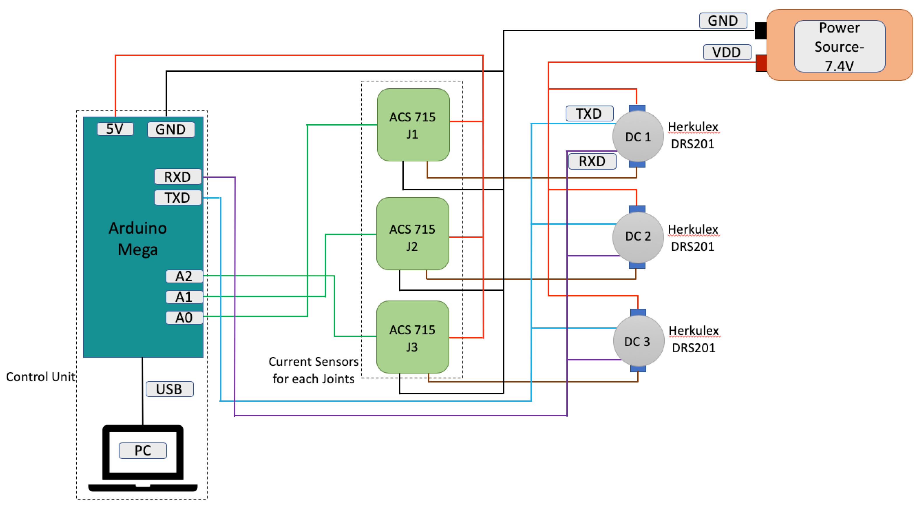
During cleaning, the platform must cover every tile, and there must not be any recoverage because it utilises excess energy. For an autonomous floor-cleaning robot, navigation energy is a critical parameter that must be investigated. Navigation energy is the sum of locomotion energy and reconfiguration energy. Both energy components entirely depend on the motors and their power requirement. This energy requirement during reconfiguration includes the speed, inertia, resistance and inductance and the rotational angle of the robot. During operation, the peak overshoot and the potential drop occurring in the system will directly influence the energy consumption of the robot, thereby making it run out of energy in some worst cases. Thus, it is necessary to include the steady state error response of the robot during the energy estimation. In this paper, we study the energy requirement during the reconfiguration process. The energy spent during reconfiguration depends on the current consumption of each hinged motor. Considering these aspects, the current consumption of each servo motor during reconfiguration was measured, and the real-time cost (navigation energy) was estimated. Each servo motor was connected to a current sensor ACS715, and all three current sensors are in serial connection as shown in
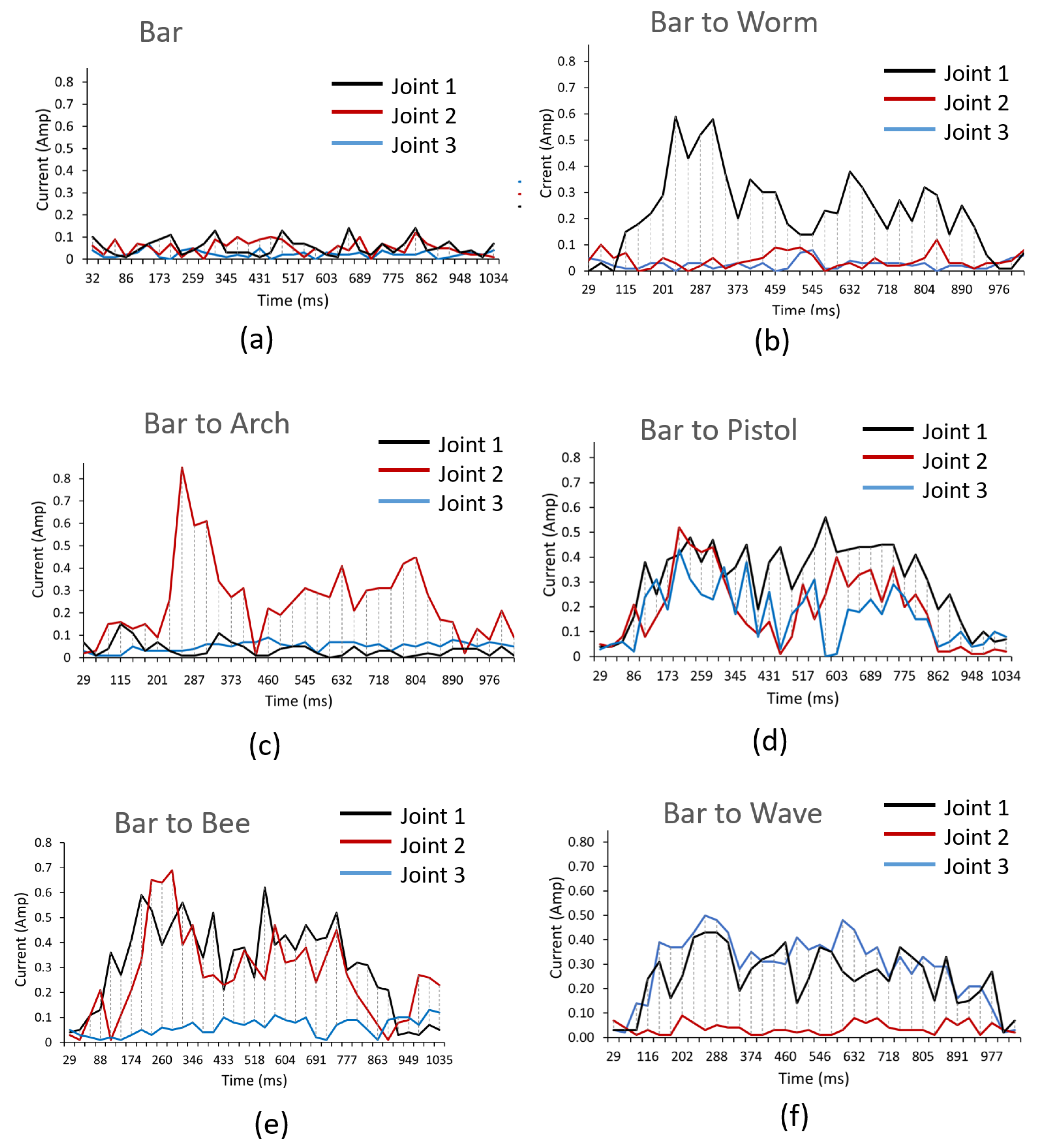
Figure 12. The input command was controlled and sent through Arduino mega. The Arduino code and logging of current data is interfaced and monitored with the help of a computer. The position feedback from the motors is transmitted and received to Arduino via TXD and RXD ports, respectively. Reconfiguration of the blocks takes place within one second, and the corresponding current consumption was monitored.
Figure 13 shows the current consumption of three joints of the platform during reconfiguration. It is clear from the experiment that the bar configuration draws the least current of all configurations. This current consumption holds the joint in a specific position. The pistol configuration consumes the maximum current because all three joints rotate at the same time. The current consumption by each hinged motor is less than the rated current of the DC servo motor (Herkulex DRS-0201).
For tiling-based path-planning, we assumed that the work-space in the presence of obstacles can be divided into sets of large honeycombs or hexagonal rectangles. Each honeycomb is further divided into six hexagonal triangles. As per the tiling theorem, each hexagonal triangle and hexagonal rectangle can be completely filled with various forms of tetrahex without any voids. In this section, based on the power consumption during reconfiguration, a comparative study was done to figure out the efficiency of the smallest hexagonal triangle and hexagonal rectangle planar tiling sets.
Table 3 shows the average power consumption by the hinged motors (both moving and non-moving) of each configuration (bar, arch, bee, pistol, wave, and worm). The amount of power consumption during the clockwise and anticlockwise rotations of each block are nearly the same. In the bar configuration, three joints are stationary, and the power consumption is the least. In other configurations, the power consumed by the moving joint is more than the non-moving joint.
Table 4 lists the number of configurations of hHoneycomb in four different planar tiling sets (
and
hexagonal rectangle, hexagonal triangle-I, and hexagonal triangle-II). For each planar tiling set, the total power consumption during reconfiguration is estimated. The
hexagonal rectangle consumes the least power of all the tiling sets. For any square and rectangular work-space, sets of
hexagonal rectangular tiles are the energy efficient tiles. However, for any honeycomb-like work-space, the hexagonal triangle-II tile is the best fit because it consumes less power.
9. Discussion
This study presents a self-reconfigurable floor cleaning robotic platform called hHoneycomb which is developed under the combinatorial properties of the polyhex. We described the reconfiguration theory, mechanism design and electronics modules of this platform and successfully demonstrated its ability to change its morphology between six one-sided tetrahex morphology with an objective of maximising the area coverage. In addition, we introduced a novel coverage path-planning technique based on polyhex tiling theory for the hHoneycomb robot to enable autonomous navigation. This platform undergoes shape-shifting and forms unique morphologies, including bee, pistol, wave, arch, and worm. These distinct morphologies help reach narrow and curved spaces of the cleaning environments. The mechanical layout and hinge location of the platform is finalised based on the finite element-based frequency and structural analysis. Based on this, the robot prototype is fabricated using PLA material. This platform has two independent actuating mechanisms for locomotion and reconfiguration. Omnidirectional wheels are used for locomotion of the platform, and the translational and zero-pivot rotational capabilities of the platform were studied from the analytical formulation of wheel kinematics. The platform’s locomotion was verified using Matlab’s Simscape module. The dynamics of the platform during reconfiguration is derived based on Euler-Lagrangian formulation. The power consumption by the each hinged joint for every configuration was measured experimentally; based on which the navigation energies for four different tile sets were estimated and during cleaning, the most efficient tiling set can be used as cover for the work-space.
Future research on hHoneycomb will focus on the following areas. The first is integrating different sensorial payloads that allow the robot platform to be used for various applications. The second is to study control aspects of the platform to achieve locomotion control. Moreover, we intend to explore the terrain-based locomotion, cleaning modules with payloads, robot control scheme including the dynamics of the system as described and on-board Simultaneous Localization and Mapping (SLAM) for autonomous operations.

 ,
, 


