Article

Comparative Analysis of Fault-Tolerant Dual-Channel BLDC and SR Motors

The Faculty of Electrical and Computer Engineering, Rzeszow University of Technology, Al. Postancow Warszawy 12, 35-959 Rzeszow, Poland
*
Author to whom correspondence should be addressed.
Energies 2019, 12(13), 2489; https://doi.org/10.3390/en12132489
Submission received: 20 May 2019 / Revised: 24 June 2019 / Accepted: 25 June 2019 / Published: 28 June 2019
(This article belongs to the Special Issue Advances in Rotating Electric Machines)

Abstract

:
This article presents the results of a comparative analysis of two electronically commutated brushless direct current machines intended for fault-tolerant drives. Two machines designed by the authors were compared: a 12/14 dual-channel brushless direct current motor (DCBLDCM) with permanent magnets and a 12/8 dual-channel switched reluctance motor (DCSRM). Information is provided here on the winding configuration, the parameters, and the power converters of both machines. We developed mathematical models of the DCBLDCM and DCSRM which accounted for the nonlinearity of their magnetization characteristics in dual-channel operation (DCO) and single-channel operation (SCO) modes. The static torque characteristics and flux characteristics of both machines were compared for operation in DCO and SCO modes. The waveforms of the current and the electromagnetic torque are presented for DCO and SCO operating conditions. For DCO mode, an analysis of the behavior of both machines under fault conditions (i.e., asymmetrical control, shorted coil, and open phase) was performed. The two designs were compared, and their strengths and weaknesses were indicated.

1. Introduction

In fault-tolerant electrical drives, two solutions are used: multiphase motors (with more than three phases) as the standard or three-phase motors with dual windings. Multiphase motors, regardless of the type of machine, usually require a more extensive power supply system and more complex control algorithms [1,2,3,4]. Three-phase motors with independent, three-phase dual windings require two independent power supply circuits [5,6,7,8,9,10,11,12,13,14,15,16,17,18,19,20,21]. As a result, two channels are obtained which, depending on the type of machine and the configuration of its windings, may be magnetically independent or partly independent. Full or significant magnetic independence between the channels makes control of such a motor much easier. This is particularly important in the case of fault-tolerant operation.
Direct current electronically commutated motors include brushless direct current motors (BLDCMs) with permanent magnets and switched reluctance motors (SRMs). BLDCMs and SRMs can be designed as standard three-phase or multiphase machines. In the case of a BLDCM, the use of more than three phases is not a typical approach [1,22,23]. In the case of switched reluctance motors, a four-phase solution is a borderline case for potential commercial applications [24]. Consequently, in fault-tolerant drives, the authors suggest using dual-channel BLDCM (DCBLDCM) or SRM (DCSRM) (i.e., ones with dual three-phase windings). In such machines, in order to achieve the same operating point, depending on the control strategy adopted, two channels or only one channel is supplied in normal operating conditions. Selection of a DCBLDCM or a DCSRM for a given drive is not self-evident.
In this study, a comparative analysis was performed of two designs of dual-channel brushless direct current electronically commutated motors with or without permanent magnets. The machines were designed for use in critical drive systems. The first machine, with permanent magnets, was designated DCBLDCM and the other, without permanent magnets, was designated DCSRM. Both machines, at the stages of their design and construction, were adapted for independent dual-channel supply, that is, for dual-channel operation (DCO) and single-channel operation (SCO).
The aim of this study was to compare the features of the DCBLDCM and the DCSRM designs in DCO and SCO, especially in the context of guaranteeing the continuation of motor operation after the occurrence of a fault condition. The rated power, rated torque and base speed of both machines are different. Therefore, the comparison of performance of both machines is difficult. For this reason, the results are presented as a ratio of value to the base values (presented in Table 1). Nevertheless, the aim of the paper is to compare the possibilities of dual-channel operation rather than the performance.
In Section 2, the DCBLDC and DCSR machine designs studied are presented and the configurations of their power supply systems, the distributions of their stator windings, and their parameters and characteristics are shown. Section 3 contains the authors’ nonlinear mathematical models of DCBLDC and DCSR machines for DCO and SCO. These mathematical models take into account the nonlinearity of the magnetic circuit and the magnetic coupling between particular phases of channels A and B. The models include novel electromagnetic torque formulas of the DCBLDCM and the DCSRM for DCO and SCO proposed by the authors. It was proven that the structure of the formulas of the mathematical model of SRM was the particular simplification of the formulas of the model of the BLDC machine assuming that PM magnetization equivalent current was zero (PM flux was neglected). Section 4 presents the static characteristics of the motors studied (the electromagnetic torque and the linkage fluxes) for DCO and SCO modes. The results of the analysis of current and electromagnetic torque waveforms presented in Section 5 are divided into two parts. The first part contains the results of an analysis of DCO and SCO, assuming the electric and magnetic symmetry of both channels. The second part describes the analysis that was performed of nonstandard operating conditions in DCO mode, such as:
  • asymmetry control of both channels,
  • short circuits of part of the winding of one of the channels, and
  • open-phase of the winding of one of the channels.
The results of the comparative analysis of the two studied machines and the conclusions are presented in Section 6.

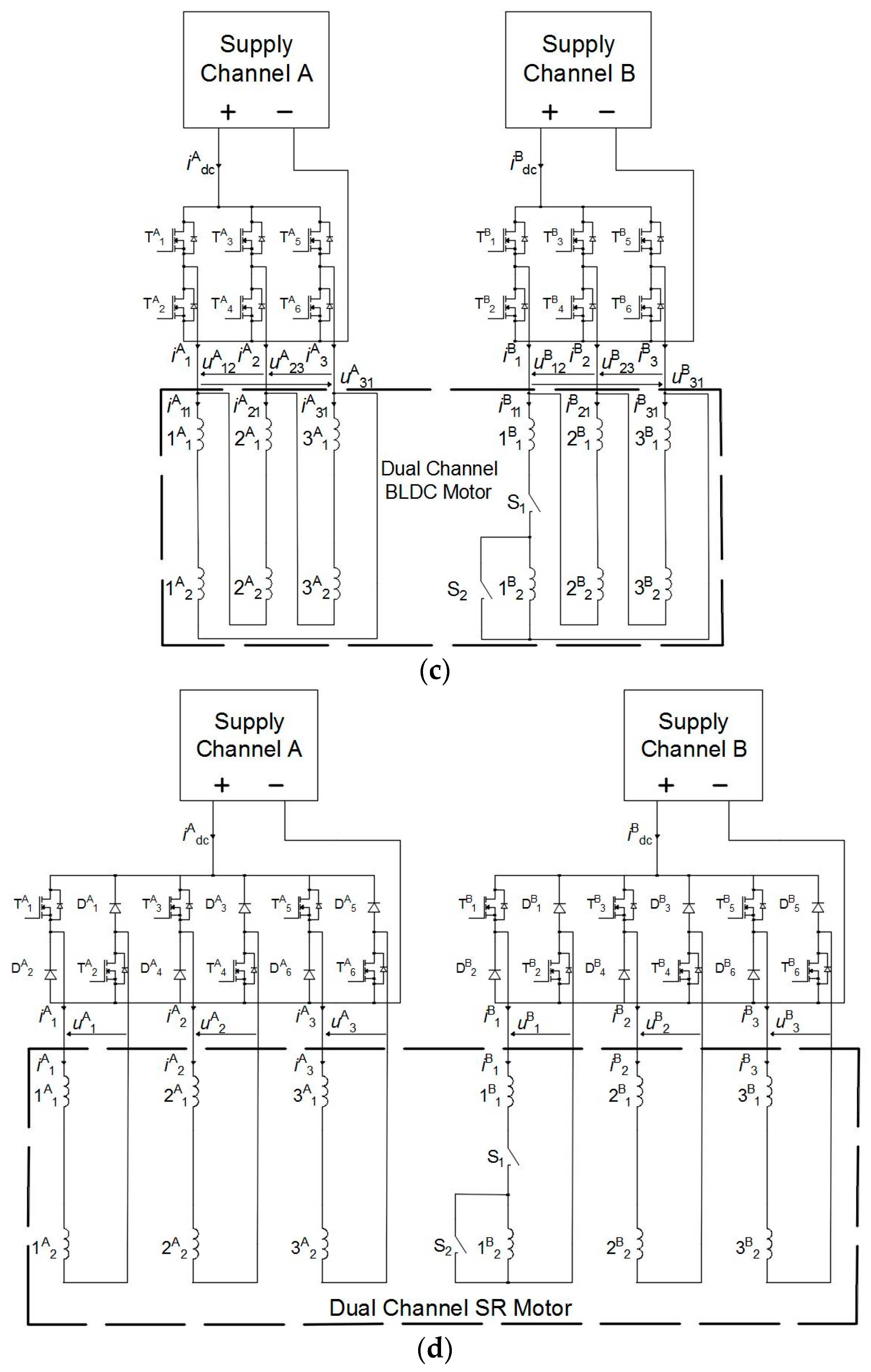
2. Analysis of the DCBLDC and DCSR Motors

An analysis was performed of two three-phase designs of brushless direct current machines. In the case of the DCBLDC motor, this was a solution with 12 stator poles and 14 rotor poles (magnets) with an external rotor (Figure 1a). The machine was designed for a small unmanned aerial vehicle (UAV). In the case of the DCSRM, a solution with 12 stator poles and 8 rotor poles was selected (Figure 1b). The DCSRM was designed for a fan drive. Both motors have the same number of stator poles. At the design stage of both motors, provisions were made for the possibility of a dual-channel power supply. There were six stator poles per channel. The use of two independent power supply channels made it possible to achieve a dual three-phase power supply in both cases. The dual-channel power supply diagram is shown in Figure 1c for the BLDCM and in Figure 1d for the SRM.
In the case of the configuration of the windings of the DCBLDC motor, the layout shown in Figure 1a (ABABAB) was used. As demonstrated in [6,24], this is the most advantageous configuration, and not only with regard to the distribution of the magnetic pull forces. In the case of the SRM, a similar principle was adopted with regard to the positions of the windings of the different channels. The configuration used (ABABABABABAB) is shown in Figure 1b. In the case of an SRM with four poles per phase, the short-flux path solution (NSNS) is usually selected [8,9]. This configuration of the poles of a single phase may also be used in the case of a dual-channel power supply [8,9,11,12]. It ensures the most advantageous motor parameters for a dual-channel power supply. However, in the authors’ opinion, in the case of a machine intended for a dual-channel power supply, the configuration with a long-flux path (NNSS) should be selected [11]. For a classic or dual-channel power supply, this configuration results in slightly poorer machine performance [11]. At the same time, it is characterized by greater magnetic independence of the different channels. The NNSS configuration of the poles of an SRM meets this condition. This is demonstrated later in this article.
Selected geometric parameters of both motors are shown in Table 1, which also contains selected electric parameters. The electric parameters were specified for the SCO power supply. The base torque obtained for the DCBLDCM was equal to TbDCBLDCM = 1.0 N⋅m, while that obtained for the DCSRM was equal to TbDCSRM = 0.5 N⋅m. The base torque in the DCBLDC was obtained when the line current was equal to IrefDCBLDCM = 36.5 A. In the case of the DCSRM, this value was IrefDCSRM = 8.5 A. The above values were adopted as a reference for presentation of the waveform of the line current (Section 5) and the electromagnetic torque in the relative values (Section 4 and Section 5) as a function of time.
Figure 2c,d show idealized torque–speed characteristics of the DCBLDCM (Figure 2c) and the DCSRM (Figure 2d). The torque–speed characteristics of the two motors were significantly different. In the case of the DCBLDCM in DCO and SCO modes, there were small differences in the base speeds. For DCO mode, the base speed was slightly higher (by several percent). In the case of the DCSRM, the differences between DCO and SCO modes were much more significant. In DCO operation mode, the base speed was up to two times higher than in SCO mode. In the case of the DCSRM, there was a constant power range regardless of the operation mode (DCO or SCO). In the case of the DCBLDCM, there was practically no constant power region.

3. A Mathematical Model of the DCBLDC and DCSR Motors Analyzed

3.1. Main Assumptions and General Equation Structure

The subjects of the mathematical modeling were dual-channel three-phase BLDC and SR machines, for which the authors’ circuit-based models, known as flux models, were proposed. The presented mathematical models of the DCBLDC and DCSR machines took into account the nonlinearity of the magnetic circuit and the magnetic couplings between particular phases within a given channel (A or B), as well as between channels (A and B). The following simplifying assumptions were made in the proposed models:
  • symmetry of the magnetic circuit structure of both the stator and the rotor;
  • decomposition of phase fluxes into a sum of fluxes induced by phase currents (leakage and main fluxes) and fluxes from permanent magnets in the DCBLDCM;
  • omission of phenomena related to eddy currents and magnetic hysteresis;
  • omission of the influence of temperature on the parameters of the machines and the fluxes generated by permanent magnets (in the DCBLDCM).
The general structure of the formulas of the circuit-based mathematical models of the three-phase dual-channel machines can be written in the following form:
[ u A u B ] = [ R A 0 0 R B ] [ i A i B ] + d d t [ ψ A ψ B ] ,
J d ω d t + D ω + T L = T e
d θ d t = ω
where for channels A and B ( k A ,   B ), the vectors representing voltages u k , currents i k , fluxes ψ k , as well as matrixes of resistances R k are defined as follows:
u k = [ u 1 k , u 2 k , u 3 k ] T ,   i k = [ i 1 k , i 2 k , i 3 k ] T , ψ k = [ ψ 1 k , ψ 2 k , ψ 3 k ] T ,   R k = d i a g ( R 1 k , R 2 k , R 3 k )
The following symbols are used in Equations (1)–(3): θ—rotor position, ω—angular velocity, J—rotor moment of inertia, D—coefficient of viscous friction, TL—load torque, and Te—electromagnetic torque. Electromagnetic torque Te in Equation (2) can be calculated as a derivative of total magnetic field coenergy in the air gap with respect to rotor position.

3.2. Mathematical Models of DCBLDC Motors

3.2.1. DCBLDCM—DCO Mode

In machines with permanent magnets, the fluxes in Equation (1) depend on the rotor position θ, the winding current, and the permanent magnets’ magnetization equivalent current, designated as iPM. The voltage–current Equation (1) and the expression for electromagnetic torque in Equation (2) for DCO can be written in the following form:
[ u A u B ] = [ R A 0 0 R B ] [ i A i B ] + d d t [ ψ A ( θ , i A , i B , i PM ) ψ B ( θ , i A , i B , i PM ) ]
T e = T e ( θ , i A , i B , i PM )
where flux linkages caused by windings’ currents and permanent magnets for both channels A and B are defined as follows:
ψ k ( θ , i A , i B , i PM ) = [ ψ 1 kPM ( θ , i PM ) + L 1 σ kk i 1 k + j = 1 3 ( l = A B ψ 1 j kl ( θ , i j l , i PM ) ) ψ 2 kPM ( θ , i PM ) + L 2 σ kk i 2 k + j = 1 3 ( l = A B ψ 2 j kl ( θ , i j l , i PM ) ) ψ 3 kPM ( θ , i PM ) + L 3 σ kk i 3 k + j = 1 3 ( l = A B ψ 3 j kl ( θ , i j l , i PM ) ) ]
In Expression (6), ψ i kPM ( θ , i PM ) are the fluxes generated by permanent magnets, and L i σ kk are the leakage fluxes (for k A , B and i = 1,2,3).
The expression for electromagnetic torque (5), with assumptions (6) taken into account, can be written in the following form:
T e ( θ , i A , i B , i PM ) = i = 1 3 ( i i A ψ i APM ( θ , i PM ) θ + i i B ψ i BPM ( θ , i PM ) θ ) + i = 1 3 ( 0 i i A ψ ii AA ( θ , i ¯ i A , i PM ) θ d i ¯ i A + 0 i i B ψ ii BB ( θ , i ¯ i B , i PM ) θ d i ¯ i B ) + i = 2 3 j = 1 i   1 ( i i A ψ ij AA ( θ , i j A , i PM ) θ + i i B ψ ij BB ( θ , i j B , i PM ) θ ) + i = 1 3 j = 1 3 ( i i B ψ ij BA ( θ , i j A , i PM ) θ ) + T cog ( θ , i PM )
Electromagnetic torque is the sum of torques from the fluxes of magnets, windings’ currents, and the cogging torque T cog . Equations (2) and (4) with Expressions (6) and (7) constitute the nonlinear mathematical model of the DCBLDC machine in DCO mode.

3.2.2. DCBLDCM—SCO Mode

In this particular case, when the DCBLDC machine is operating in SCO mode (e.g., only channel A or B is supplied), Equations (4) and (6), as well as the expression for torque (7), can be simplified (for k A , B ):
[ u 1 k u 2 k u 3 k ] = [ R 1 k 0 0 0 R 2 k 0 0 0 R 3 k ] [ i 1 k i 2 k i 3 k ] + d d t [ ψ 1 kPM ( θ , i PM ) + L 1 σ kk i 1 k + j = 1 3 ( ψ 1 j kk ( θ , i j k , i PM ) ) ψ 2 kPM ( θ , i PM ) + L 2 σ kk i 2 k + j = 1 3 ( ψ 2 j kk ( θ , i j k , i PM ) ) ψ 3 kPM ( θ , i PM ) + L 3 σ kk i 3 k + j = 1 3 ( ψ 3 j kk ( θ , i j k , i PM ) ) ]
T e ( θ , i 1 k , i 2 k , i 3 k , i PM ) = i = 1 3 ( i i k ψ i kPM ( θ , i PM ) θ ) + i = 1 3 ( 0 i i k ψ ii kk ( θ , i ¯ k i , i PM ) θ d i ¯ i k ) + i = 2 3 j = 1 i 1 ( i i k ψ ij kk ( θ , i j k , i PM ) θ )         + T cog ( θ , i PM )
Equations (8) and (2) with Expression (9) constitute the nonlinear mathematical model of the DCBLDC machine in SCO mode.

3.3. Mathematical Models of DCSR Motors

3.3.1. DCSRM—DCO Mode

The equations of the mathematical model of DCSR machines can also be derived from the equations of DCBLDC machines by eliminating the relevant fluxes produced by permanent magnets. The voltage–current Equation (1) and the equation of motion of a circuit-based mathematical model of the DCSRM for DCO mode can be written in the following form:
[ u A u B ] = [ R A 0 0 R B ] [ i A i B ] + d d t [ ψ A ( θ , i A , i B ) ψ B ( θ , i A , i B ) ]
T e = T e ( θ , i A , i B )
where for channels k A , B , flux linkages caused only by winding currents ψ k ( θ , i A , i B ) are defined as follows:
ψ k ( θ , i A , i B ) = [ L 1 σ kk i 1 k + j = 1 3 ( l = A B ψ 1 j kl ( θ , i j l ) ) L 2 σ kk i 2 k + j = 1 3 ( l = A B ψ 2 j kl ( θ , i j l ) ) L 3 σ kk i 3 k + j = 1 3 ( l = A B ψ 3 j kl ( θ , i j l ) ) ]
For the DCO mode of the DCSRM, the expression for electromagnetic torque, with assumptions taken into account, can be written in the following form:
T e ( θ , i A , i B ) = i = 1 3 ( 0 i i A ψ ii AA ( θ , i ¯ i A ) θ d i ¯ i A + 0 i i B ψ ii BB ( θ , i ¯ i B ) θ d i ¯ i B )       + i = 2 3 j = 1 i   1 ( i i A ψ ij AA ( θ , i j A ) θ + i i B ψ ij BB ( θ , i j B ) θ ) + i = 1 3 j = 1 3 ( i i B ψ ij BA ( θ , i j A ) θ )

3.3.2. DCSRM—SCO Mode

In the particular case where the DCSRM is operating in SCO mode (e.g., only channel A or B is supplied), Equation (10) with the expression for torque (13) can be simplified ( k A   or   B ):
[ u 1 k u 2 k u 3 k ] = [ R 1 k 0 0 0 R 2 k 0 0 0 R 3 k ] [ i 1 k i 2 k i 3 k ] + d d t [ L 1 σ kk i 1 k + j = 1 3 ( ψ 1 j kk ( θ , i j k ) ) L 2 σ kk i 2 k + j = 1 3 ( ψ 2 j kk ( θ , i j k ) ) L 3 σ kk i 3 k + j = 1 3 ( ψ 3 j kk ( θ , i j k ) ) ]
T e ( θ , i 1 k , i 2 k , i 3 k ) = i = 1 3 ( 0 i i k ψ ii kk ( θ , i ¯ i k ) θ d i ¯ i k ) + i = 2 3 j = 1 i 1 ( i i k ψ ij kk ( θ , i j k ) θ )
Equations (14) and (2) with Expression (15) constitute the nonlinear mathematical model of the DCSRM in SCO mode.
Based on the presented equations for the BLDCM in DCO and SCO modes, it is possible to obtain models for special simplifying assumptions, for example, by omitting couplings between particular phases or channels A and B.

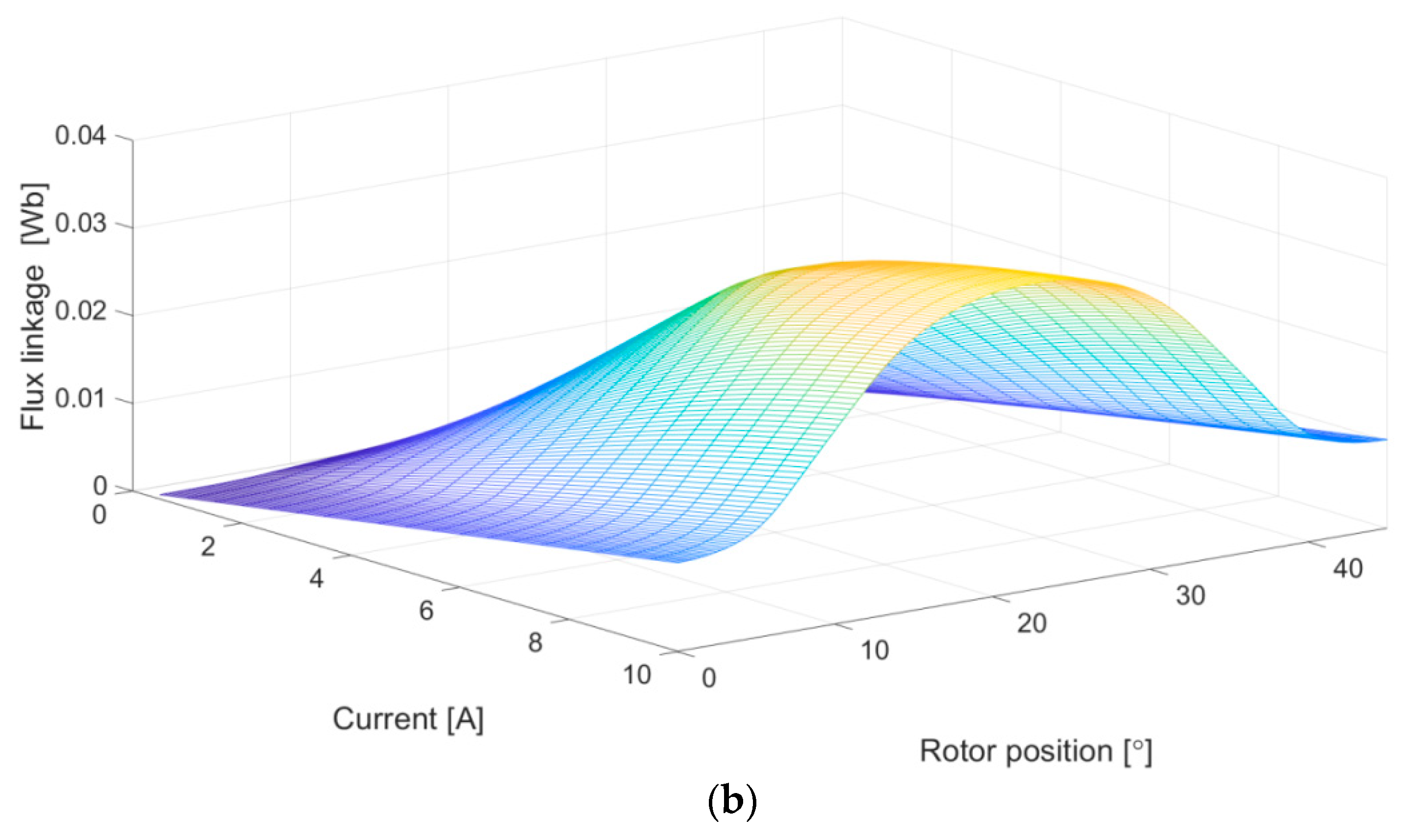
3.4. Flux Characteristics for Simulation Models
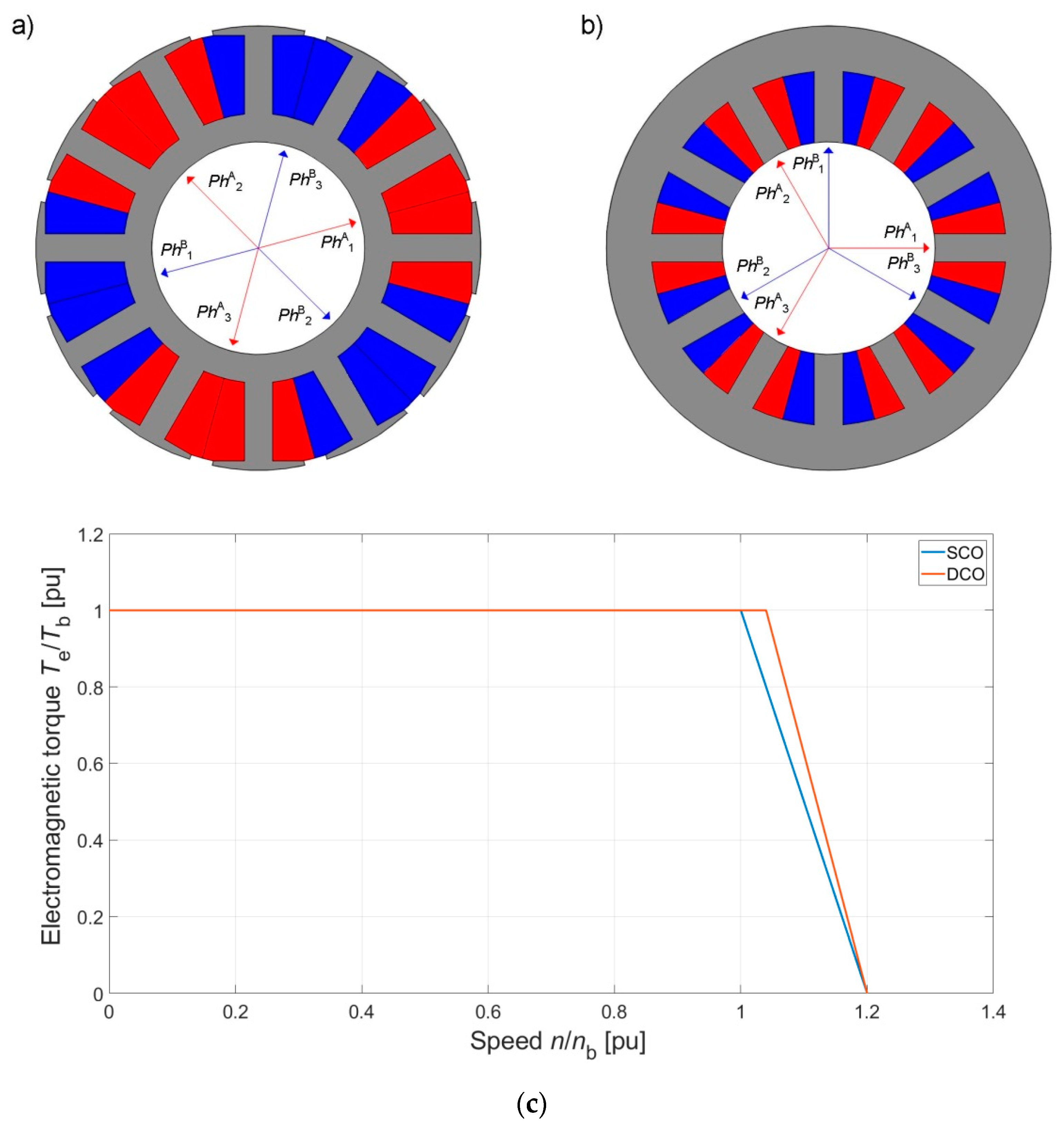
The relationships of fluxes as a function of rotor position and phase current were determined by means of 2D field methods (finite element method) and then the obtained set of relationships was used in the circuit models. For example, Figure 3 shows 3D views of flux linkage ψ 1 A of the first phase of channel A as a function of rotor position θ and current i 1 A for a DCBLDCM (Figure 3a) and a DCSRM (Figure 3b).

4. Static Analysis

Static calculations were performed for the reference values of currents given in Table 1 that were required for SCO mode. For DCO mode, the reference values of currents were reduced in order to obtain a comparable shape of the static torque characteristic.

4.1. Characteristics of the DCBLDCM

Figure 4a shows the determined static characteristics of electromagnetic torque as a function of rotor position for DCO and SCO modes. In the case of DCO mode, the reference value of the current was reduced to 50% of the value specified in Table 1. The results of laboratory tests are shown in Figure 4b. Laboratory tests were performed for I = 0.5 Iref (i.e., iA = iB = 0.25 Iref for DCO mode and iA = 0.5 Iref, iB = 0 for SCO mode (channel A) and iA = 0 Iref, iB = 0.5 Iref for SCO mode (channel B)). The fluxes linked with the different windings for DCO mode are shown in Figure 4c. The linkage fluxes for SCO mode are shown in Figure 4d.
In dual-channel mode, the brushless motor with a permanent magnet required half of the value of the reference current of SCO mode in order to obtain the required value of the base torque. This was quite beneficial from the point of view of the control algorithm of the operation of a motor supplied from two channels. The configuration used was characterized by very high magnetic independence between the two channels. The magnetic couplings between the two channels in normal operating conditions were minimal. The linkage fluxes of the windings of the channel that was not being supplied (Figure 4d) came mainly from permanent magnets. The assumption made in the mathematical model that the two channels of the presented design are magnetically independent significantly simplified the equations of the mathematical model of the DCBLDCM.

4.2. Characteristics of the DCSRM

In the case of a switched reluctance motor, the relationship between DCO and SCO modes is more complex. This is largely due to this machine’s principle of operation. Unfortunately, the principle that, in DCO mode, the reference value of the current should be equal to 50% of the value in SCO mode, which applies to the DCBLDCM, could not be adopted here. Due to the nonlinear relationship between the value of the generated electromagnetic torque and the current, achieving the same value of electromagnetic torque in DCO mode requires a current greater than 50% of the reference value of SCO mode. In the analyzed case, the required level was 70%. Figure 5a shows the relationship between the electromagnetic torque as a function of rotor position for DCO and SCO modes of the SRM. Examples of characteristics determined in laboratory conditions are shown in Figure 5b. Laboratory tests were performed for I = 0.5 Iref (i.e., iA = 0.5 Iref, iB = 0 for SCO mode (channel A); iA = 0, iB = 0.5 Iref for SCO mode (channel B); and iA = iB = 0.35 Iref for DCO mode). The characteristics of the linkage flux for DCO mode are shown in Figure 5c, and those for SCO mode in Figure 5d.
In the case of the SRM, the saturation of a magnetic circuit affected the relationship between DCO and SCO modes. This can be seen in the torque characteristics (Figure 5a) and the flux characteristics (Figure 5c,d). However, the impact of magnetic couplings between the two channels was small (Figure 5d). For this configuration, it can also be assumed that both channels were characterized by a very big magnetic separation. This is why this specific configuration of pole windings was selected for the dual-channel power supply (Figure 1b).

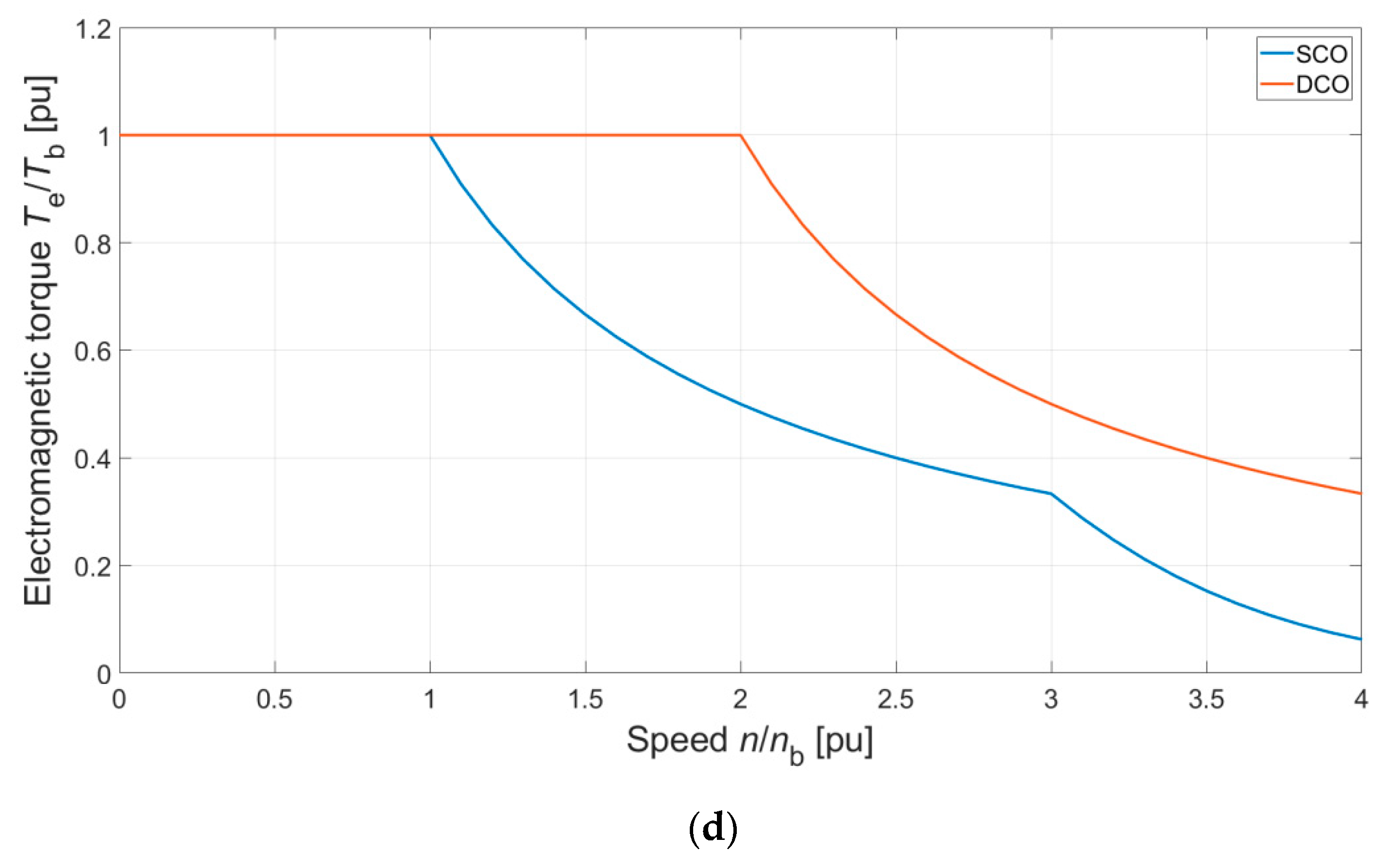
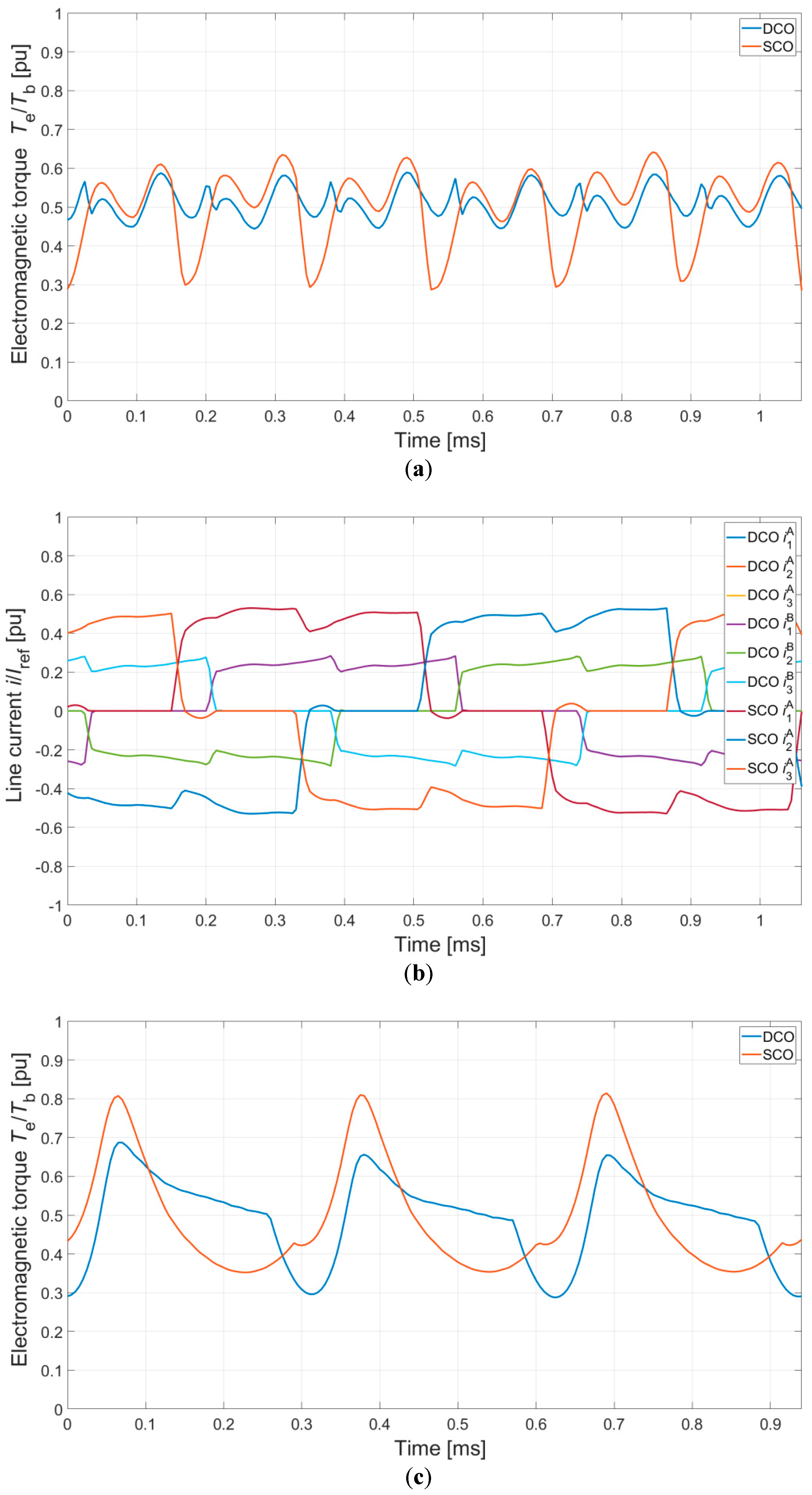
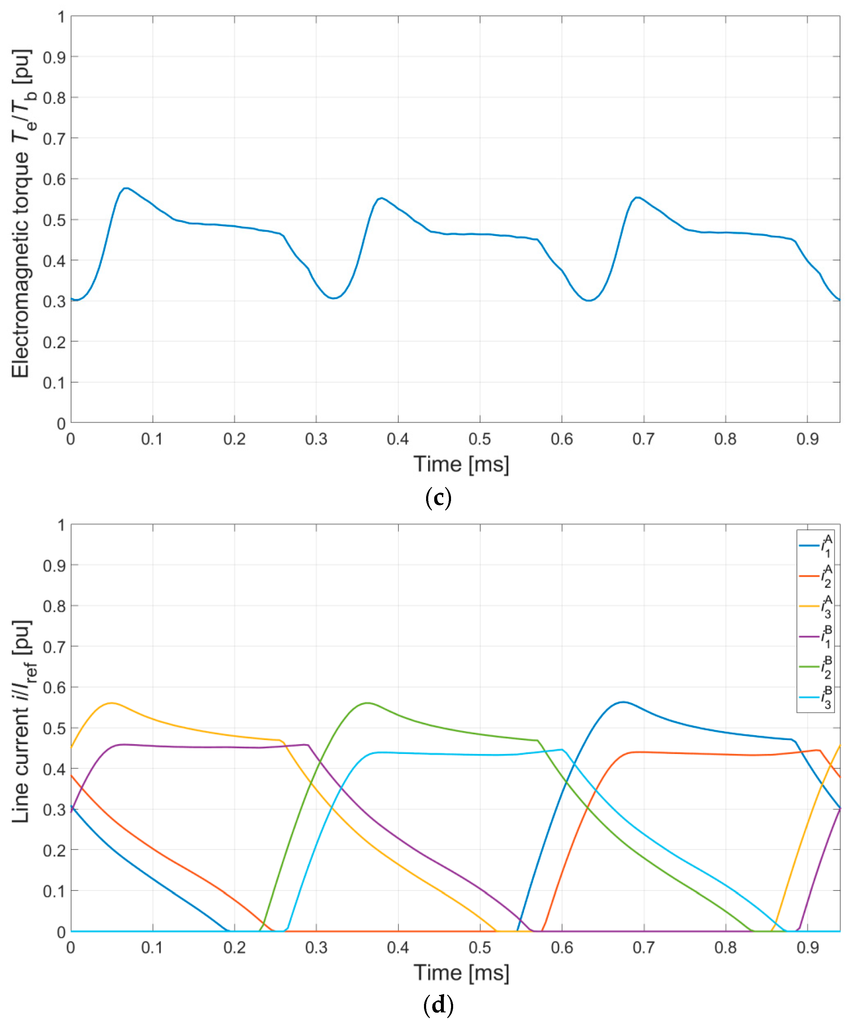
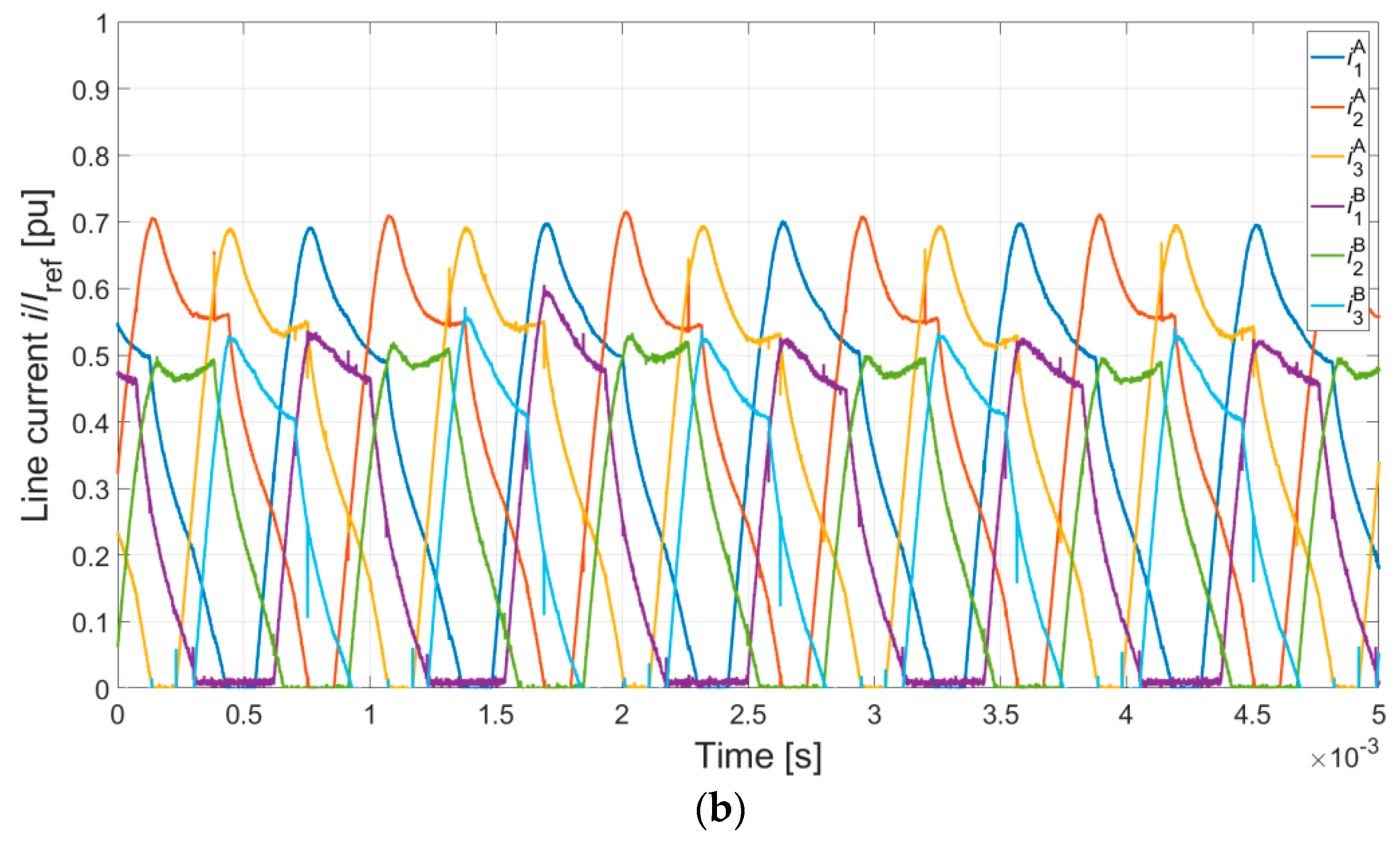
5. Transient Analysis

5.1. DCO and SCO

An analysis of DCO and SCO of both motors was performed for two cases: operation at low rotational speed and operation at high rotational speed. In the first operating point, both motors worked with constant torque, which required use of a current controller. The second operating point was located on the natural characteristic. Like in the previous section, the obtained waveforms of the electromagnetic torque and the line currents were compared with the base values specified in Table 1. In SCO mode, it was assumed that only channel A of the machine would be supplied.

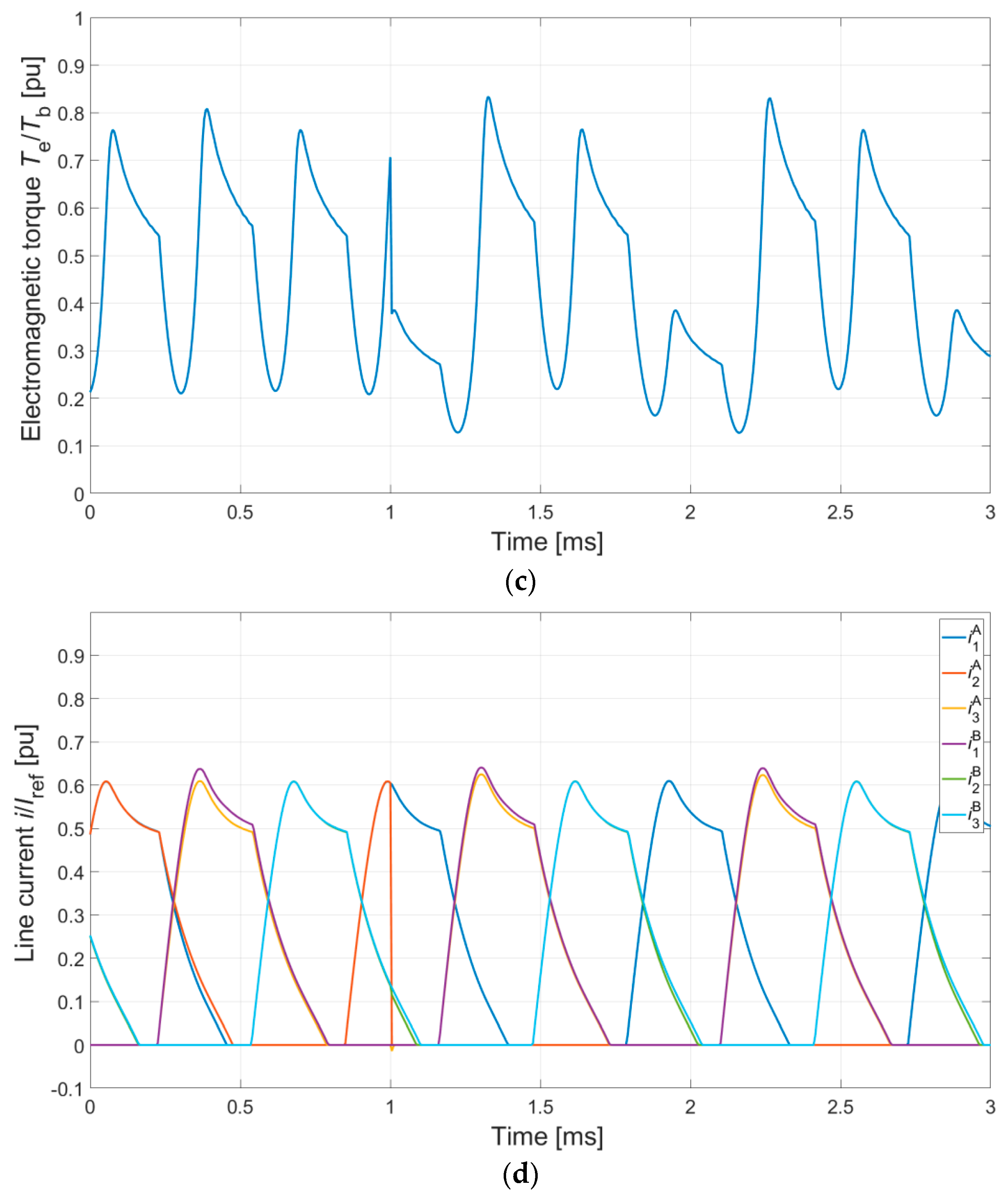
5.1.1. Constant Torque Operation

For this operating point, the numerical calculations were performed for the speed of n = 2000 r/min. It was assumed that the electromagnetic torque Te was equal to the base value given in Table 1. The obtained results are shown in Figure 6.
The comparison of the waveforms of the electromagnetic torque and the currents led to the conclusion that, in this range of operation, there were no significant differences between DCO and SCO modes for the DCBLDCM (Figure 6a,b). In DCO mode, half of the value of the reference current for SCO mode was required. The torque ripple in the case of DCBLDCM was 32% in DCO mode and 31% in SCO mode. Slightly greater differences were observed for DCO and SCO modes of the DCSRM (Figure 6d) in the waveforms of both the electromagnetic torque and the currents. In the case of SCO mode, a greater electromagnetic torque ripple (34%) was observed in comparison with DCO mode (27%). The main cause of the increase in electromagnetic torque ripple was the changed shape of the static torque characteristic (Figure 5a). In order to obtain the same value of electromagnetic torque in DCO mode, the DCSRM required a reduction of the value of the reference current (to 70%). In the case of DCO mode, the impact of magnetic couplings between the channels was unnoticeable.

5.1.2. Operation without Current Control

In the case of operation at the rated speed (n = 8000 r/min), there was no control of the line current. In the calculations, it was assumed that at this operating point, both motors would generate the rated torque equal to half of the value of the base torque. However, achieving the same value of electromagnetic torque in SCO mode is more complex. In the case of the DCSRM, a change of the turn-on and dwell angle provides great possibilities. In the case of the DCBLDCM, one can also change the turn-on angle in order to increase the value of the generated electromagnetic torque [25]. Another way to achieve the same value of electromagnetic torque in SCO and DCO modes in this part of the characteristic is to use PWM control. This applies to both motors. In the numerical calculations, the turn-on angle was changed in both motors. In the case of the DCBLDCM, in DCO mode, the turn-on angle was not changed. Figure 7 shows the results of the numerical calculations in the analyzed operating point.
In the case of operation at high rotational speed (without current control), the differences between DCO and SCO modes were more noticeable. This applied to both motors. In SCO mode, the electromagnetic torque ripple increased (42% (Figure 7a) and 65% (Figure 7c)). In DCO mode, the torque ripple was reduced (DCBLDCM—13% and DCSRM—39%). In the case of the DCSRM, torque ripple was always greater, regardless of the mode of operation. In the case of the DCSRM, in DCO mode, there was a noticeable small impact of magnetic couplings between the channels (Figure 7d).
Figure 8 shows examples of waveforms of line currents in DCO and SCO modes for both motors, measured in laboratory conditions. The laboratory system used in the tests is discussed in [25].
In the real system, the differences between DCO and SCO modes were greater. This was due to the differences in the electric and magnetic parameters of the different phases of both channels. However, the waveforms of the current confirmed the results of the numerical calculations shown in Figure 7b,d.

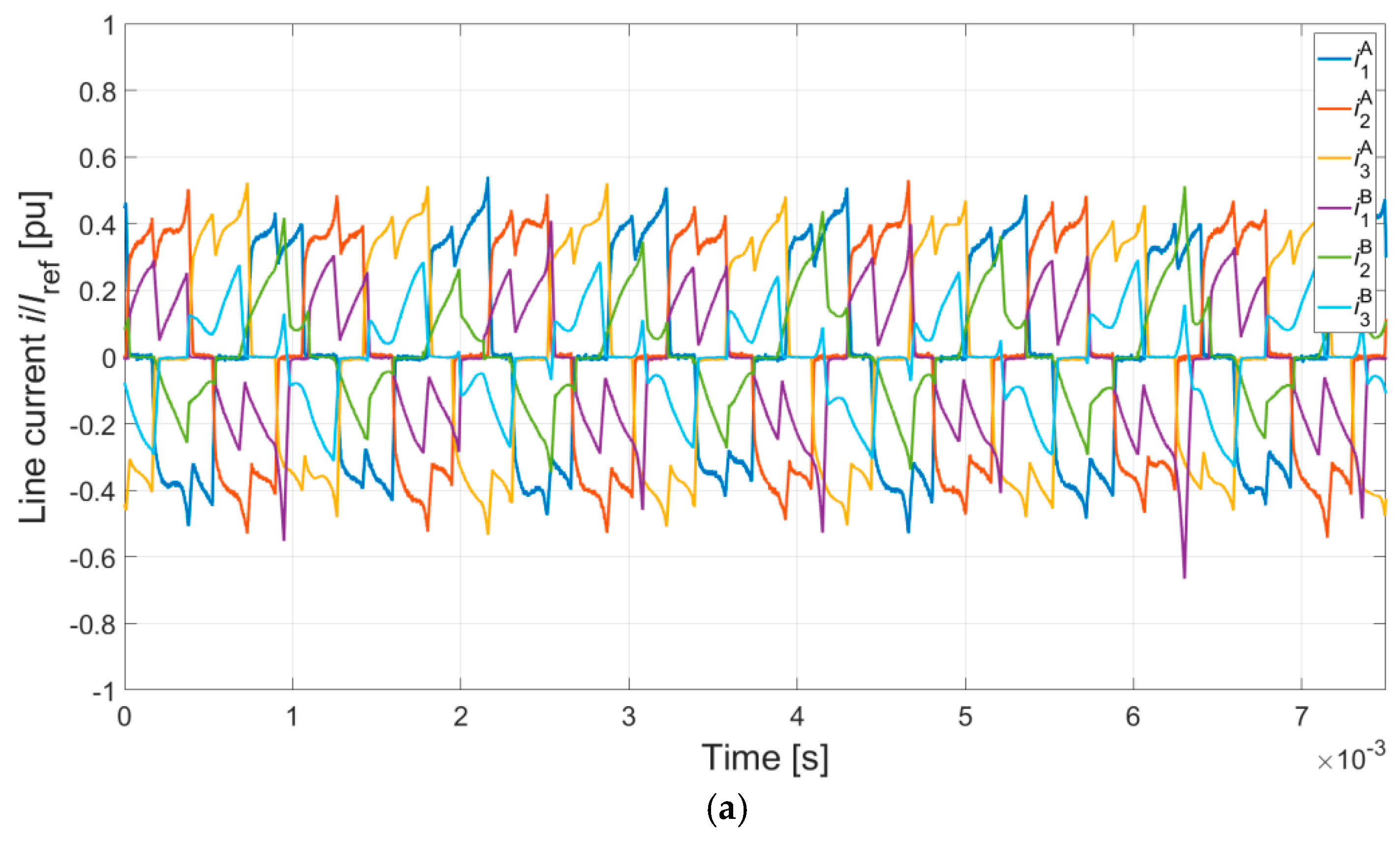
5.2. Influence of Asymmetrical Control in DCO Operation

In the analysis of DCO mode described in Section 5.1, both channels were controlled symmetrically. The test of magnetic independence for both machines was an analysis of a case where they are controlled asymmetrically. Use of two independent power supply channels (Figure 1c,d) allowed independent control of each channel. An analysis of the impact of asymmetric control was performed for a high rotational speed (n = 8000 r/min). In the calculations, it was assumed that the control parameters of channel A were the same as those specified in Section 5.1. In the case of channel B, the value of the turn-on angle was changed, and in the case of the DCSRM, the dwell angle was additionally changed. The results of the calculations are shown in Figure 9. Examples of results of laboratory tests are shown in Figure 10.
Application of the asymmetrical control for the DCBLDCM caused an increase of the average value of electromagnetic torque and the torque ripple (23%). For the DCSRM at asymmetrical control, the trend of the average value of electromagnetic torque depends on the control angles. At the same time, it is feasible to suppress the torque ripple. In the case presented in Figure 9c, the torque ripple was 29%.
The results of the laboratory test showed that both designs were characterized by very high magnetic independence between the channels. This was confirmed by the results of laboratory tests shown in Figure 10. In the case of the DCSRM, this justified the adoption of the “NNSS” configuration. Such high magnetic independence between the channels in both solutions provides great possibilities, also in the case of generator operation.

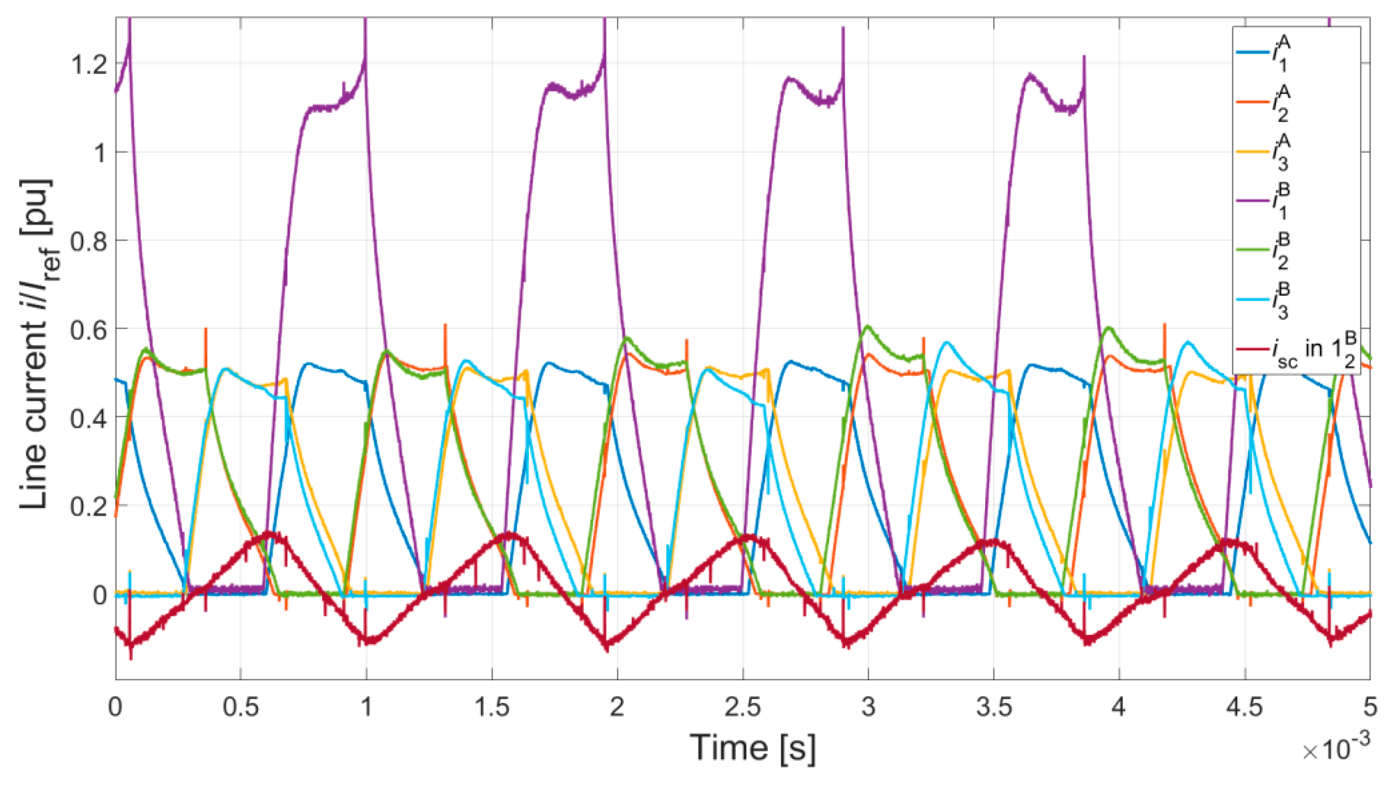
5.3. Influence of Shorted Coil in DCO Mode

Defects inside the machine are one of the typical fault conditions. Usually, these are various short circuits inside the windings of the machine. This article includes an analysis of a short circuit in part of the winding of channel B of phase 1 2 B (the entire coil is shown in Figure 1c,d). The analysis was performed during operation at a high rotational speed (n = 8000 r/min). The shorted coil was simulated using an additional switch S2 (Figure 1c,d). At the selected time, a short circuit in the coil occurred. In the case of the DCBLDCM, the short circuit occurred at t = 0.66 s. In the case of the DCSRM, the short circuit occurred at t = 1.0 s. Figure 11 shows the results of the numerical calculations.
Occurrence of a fault operating condition in the form of a short circuit in a part of the winding has a negative impact on the service life of machines. This applies in particular to DCBLDCM machines. In the shorted part of the winding, a very high current is present (Figure 11b), which causes thermal damage to the winding. However, this is not the only negative impact of this defect. Disconnecting the defective channel has practically no influence on the value of the short-circuit current. Consequently, further operation of a DCBLDCM machine with this defect is practically impossible. Moreover, the fault operating condition causes substantial torque ripple (497% in the presented case). Under certain conditions, it is possible to suppress it by application of appropriate drive system topology [21]. Nevertheless, it has no influence on the value of the short-circuit current.
Unlike a DCBLDCM, in the case of a DCSRM, occurrence of a partial short circuit in the winding is not a critical condition. After an electromagnetic balance is reached, a small short-circuit current flows in the shorted part of the winding (Figure 11d). Much more problematic are the consequences of an unbalanced magnetic pull and the torque ripple (92%). However, the machine can continue to operate with a defective channel. Here, the experimental results of operation under the pole 1 2 B short-circuit condition are presented (Figure 12). The used motor controller could not operate in current-control mode. A small current flowed in the shorted part of the winding. In the rest of the winding, the current became two times greater. However, it had a noticeable influence on the other current waveforms. In comparison with the simulation results, this influence was more significant. The impact of the control parameters and the second channel on the short-circuit current was minor.

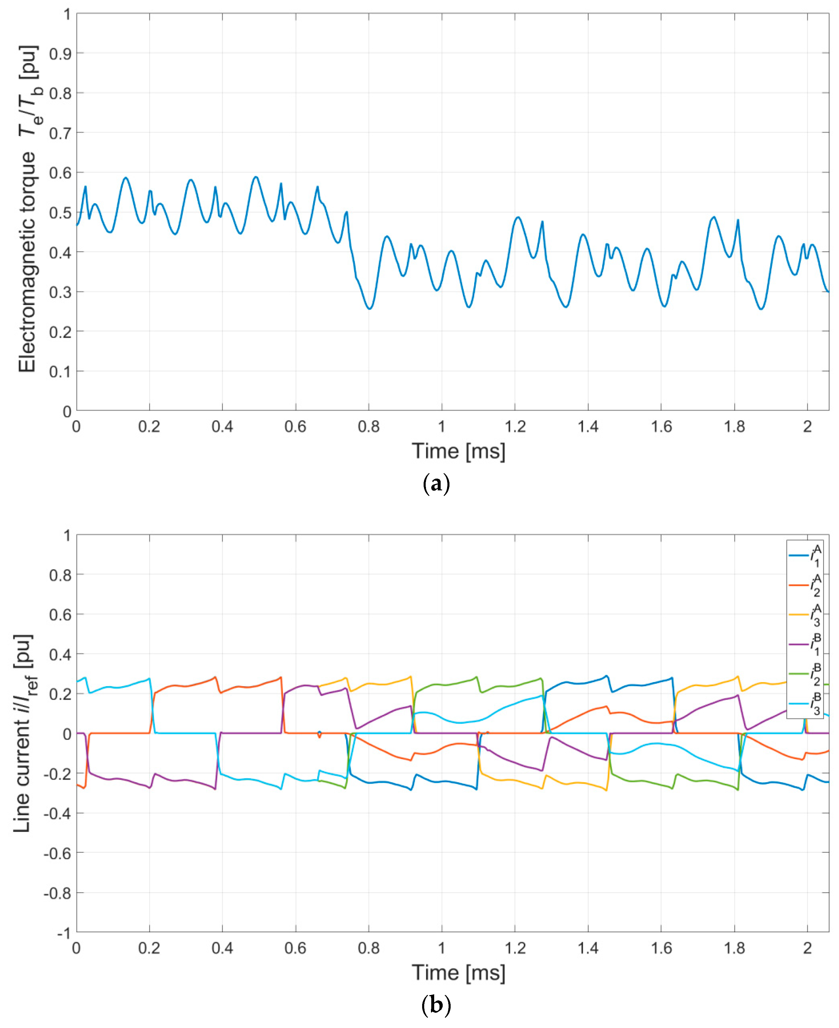
5.4. Influence of an Open Phase in DCO Mode

Another analyzed case of failure operation was an open winding in phase 1B of channel B. Like the short-circuit condition described in Section 5.2, the defect of phase 1B was simulated. At a certain point in time, the switch S1 was opened (Figure 1c,d). The defect of phase 1B in the DCBLDM occurred at t = 0.7 s, and in the DCSRM, at t = 1 s. The results of the numerical calculations are shown in Figure 13.
The failure condition caused by an open winding in one of the phases of channel B prevents further operation of machines in SCO mode. In DCO mode, after this defect occurs, a DCSR machine can continue to operate. In the case of a DCBLDC machine with delta-connected windings, this is also possible. Here, in both cases, the torque ripple increased (DCBLDCM—64% and DCSRM—165%). In the case of the DCSRM, the analyzed fault condition was identical to a defect of one or even both transistors in the power supply system. In laboratory conditions, in the case of the DCBLDCM, the detection of rotor position was based on a sensorless control algorithm. Failure to supply one of the phases of channel B resulted in errors in detection of rotor position in the defective channel (Figure 14a). Start-up of the DCBLDCM was possible with defective channel B (and with channel A not being supplied).

6. Conclusions

This study compared two dual-channel electronically commutated motors: a DCBLDCM and a DCSRM. However, it was not a full comparison and it was focused on selected operation modes. The analysis excluding thermal, vibroacoustic and efficiency aspects was performed. We proposed a mathematical model for a three-phase DCBLDC machine that considered the nonlinearity of the magnetization characteristics and all couplings between the channels. We presented a model of a DCSRM machine and demonstrated that the structure of its equations can be derived from the DCBLDCM model by omitting all components related to fluxes generated by permanent magnets. In the case of both designs, it is possible to omit the couplings between the channels in symmetrical control conditions. As demonstrated, nontypical operating conditions result in a much greater impact of couplings between the channels in the analyzed DCBLDCM design. The DCBLDCM solution is better in symmetrical control conditions due to higher torque-to-mass ratio (Table 1). However, the DCSRM solution is characterized by much greater tolerance and reliability. In the case of a DCSRM, a short-circuit condition in a part of the winding of one of the phases does not prevent further operation of the drive system. In the case of a DCBLDCM, on the other hand, occurrence of such a failure condition is a critical failure that can bring the drive system to a stop. Switching a DCBLDCM into SCO mode does not reduce the value of the short-circuit current. This problem is not present in the case of a DCSRM. A DCSRM switches into SCO mode without any problems and the current in the shorted winding of one channel does not influence the operation of the remaining channels of the drive system.

Author Contributions

Conceptualization, M.K., Formal analysis, J.P., Investigation, M.K., J.P., B.P. and G.P., Methodology, M.K. and J.P., Project administration, M.K. and B.P., Software, M.K. and B.P., Supervision, J.P. and P.B., Visualisation, M.K. and G.P., Writing-original draft, M.K., Writing-review & editing, J.P., P.B., B.P. and G.P.

Funding

This work is financed in part by the statutory funds of the Department of Electrodynamics and Electrical Machine Systems, Rzeszow University of Technology and in the part by Polish Ministry of Science and Higher Education under the program “Regional Initiative of Excellence” in 2019 – 2022. Project number 027/RID/2018/19, amount granted 11 999 900 PLN.

Conflicts of Interest

The authors declare no conflict of interest.

References

  1. Parsa, L.; Toliyat, H.A. Five-Phase Permanent-Magnet Motor Drives. IEEE Trans. Ind. Appl. 2005, 41, 30–37. [Google Scholar] [CrossRef]
  2. Levi, E.; Jones, M.; Vukosavic, S.N. A series-connected two-motor six-phase drive with induction and permanent magnet machines. IEEE Trans. Energy Convers. 2006, 21, 121–129. [Google Scholar] [CrossRef]
  3. Zheng, P.; Sui, Y.; Zhao, J.; Tong, C.; Lipo, T.A.; Wang, A. Investigation of a Novel Five-Phase Modular Permanent-Magnet In-Wheel Motor. IEEE Trans. Magn. 2011, 47, 4084–4087. [Google Scholar] [CrossRef]
  4. Zhou, Y.; Lin, X.; Cheng, M. A Fault-Tolerant Direct Torque Control for Six-Phase Permanent Magnet Synchronous Motor with Arbitrary Two Opened Phases Based on Modified Variables. IEEE Trans. Energy Convers. 2016, 31, 549–556. [Google Scholar] [CrossRef]
  5. Radun, A.V.; Ferreira, C.A.; Richter, E. Two-channel switched reluctance starter/generator results. IEEE Trans. Ind. Appl. 1998, 34, 1026–1034. [Google Scholar] [CrossRef]
  6. Chai, J.; Wang, J.; Atallah, K.; Howe, D. Performance Comparison and Winding Fault Detection of Duplex 2-Phase and 3-Phase Fault-Tolerant Permanent Magnet Brushless Machines. In Proceedings of the 2007 IEEE Industry Applications Annual Meeting, New Orleans, LA, USA, 23–27 September 2007; pp. 566–572. [Google Scholar]
  7. Barcaro, M.; Nicola Bianchi, N.; Magnussen, F. Analysis and Tests of a Dual Three-Phase 12-Slot 10-Pole Permanent-Magnet Motor. IEEE Trans. Ind. Appl. 2010, 46, 2355–2362. [Google Scholar] [CrossRef]
  8. Ding, W.; Liang, D.; Sui, H. Dynamic Modeling and Performance Prediction for Dual-Channel Switched Reluctance Machine Considering Mutual Coupling. IEEE Trans. Magn. 2010, 46, 3652–3663. [Google Scholar] [CrossRef]
  9. Ding, W.; Liang, D. Comparison of transient and steady-state performances analysis for a dual-channel switched reluctance machine operation under different modes’. IET Electr. Power Appl. 2010, 4, 603–617. [Google Scholar] [CrossRef]
  10. Barcaro, M.; Bianchi, N.; Magnussen, F. Six-Phase Supply Feasibility Using a PM Fractional-Slot Dual Winding Machine. IEEE Trans. Ind. Appl. 2011, 47, 2042–2050. [Google Scholar] [CrossRef]
  11. Ding, W.; Liu, L.; Lou, J.; Liu, Y. Comparative Studies on Mutually Coupled Dual-Channel Switched Reluctance Machines with Different Winding Connections. IEEE Trans. Magn. 2013, 49, 5574–5589. [Google Scholar] [CrossRef]
  12. Ding, W.; Lou, J.; Liu, L. Improved decoupled model of mutually coupled dual-channel SRM with consideration of magnetic saturation in dual-channel operation. IET Electr. Power Appl. 2013, 7, 427–440. [Google Scholar] [CrossRef]
  13. Ding, W.; Liu, Y.; Hu, Y. Performance evaluation of a fault-tolerant decoupled dual-channel switched reluctance motor drive under open-circuits. IET Electr. Power Appl. 2014, 8, 117–130. [Google Scholar] [CrossRef]
  14. Jiang, X.; Huang, W.; Cao, R.; Hao, Z.; Li, J.; Jiang, W. Analysis of a Dual-Winding Fault-Tolerant Permanent Magnet Machine Drive for Aerospace Applications. IEEE Trans. Magn. 2015, 51, 8114704. [Google Scholar] [CrossRef]
  15. Jiang, X.; Huang, W.; Cao, R.; Hao, Z.; Jiang, W. ‘Electric Drive System of Dual-Winding Fault-Tolerant Permanent-Magnet Motor for Aerospace Applications’. IEEE Trans. Ind. Electron. 2015, 62, 7322–7330. [Google Scholar] [CrossRef]
  16. Mese, E.; Yasa, Y.; Akca, H.; Aydeniz, M.G.; Garip, M. Investigating Operating Modes and Converter Options of Dual Winding Permanent Magnet Synchronous Machines for Hybrid Electric Vehicles. IEEE Trans. Energy Convers. 2015, 30, 285–295. [Google Scholar] [CrossRef]
  17. Bai, H.; Zhu, J.; Qin, J.; Sun, J. Fault-tolerant control for a dual-winding fault-tolerant permanent magnet motor drive based on SVPWM. IET Power Electron. 2017, 10, 509–516. [Google Scholar] [CrossRef]
  18. Chen, Q.; Xu, D.; Xu, L.; Wang, J.; Lin, Z.; Zhu, X. Fault-Tolerant Operation of a Novel Dual-Channel Switched Reluctance Motor Using Two 3-Phase Standard Inverters. IEEE Trans. App. Supercond. 2018, 28, 5204205. [Google Scholar] [CrossRef]
  19. Miyama, Y.; Ishizuka, M.; Kometani, H.; Akatsu, K. Vibration Reduction by Applying Carrier Phase-Shift PWM on Dual Three-Phase Winding Permanent Magnet Synchronous Motor. IEEE Trans. Ind. Appl. 2018, 54, 5998–6004. [Google Scholar] [CrossRef]
  20. Zhu, J.; Bai, H.; Wang, X.; Li, X. Current Vector Control Strategy in a Dual-Winding Fault-Tolerant Permanent Magnet Motor Drive. IEEE Trans. Energy Convers. 2018, 33, 2191–2199. [Google Scholar] [CrossRef]
  21. Jiang, X.; Li, Q.; Huang, W.; Cao, R. A Dual-Winding Fault-Tolerant Motor Drive System Based on the Redundancy Bridge Arm. IEEE Trans. Ind. Electron. 2019, 66, 654–662. [Google Scholar] [CrossRef]
  22. Mecrow, B.C.; Jack, A.G.; Atkinson, D.J.; Green, S.R.; Atkinson, G.J.; King, A.; Green, B. Design and testing of a four-phase fault-tolerant permanent-magnet machine for an engine fuel pump. IEEE Trans. Energy Convers. 2004, 19, 671–678. [Google Scholar] [CrossRef]
  23. Ursu, D.; Gradinaru, V.; Fahimi, B.; Boldea, I. Six-Phase BLDC Reluctance Machines: FEM-Based Characterization and Four-Quadrant Control. IEEE Trans. Ind. Appl. 2015, 51, 2105–2115. [Google Scholar] [CrossRef]
  24. Wang, S.; Zhan, Q.; Ma, Z.; Zhou, L. Implementation of a 50-kW four-phase switched reluctance motor drive system for hybrid electric vehicle. IEEE Trans. Magn. 2005, 41, 501–504. [Google Scholar] [CrossRef]
  25. Korkosz, M.; Bogusz, P.; Prokop, J. Modelling and experimental research of fault-tolerant dual-channel brushless DC motor. IET Electr. Power Appl. 2018, 12, 787–796. [Google Scholar] [CrossRef]
Figure 1. The geometry and prototypes of dual-channel power supplied brushless electronically commutated motors. (a) The geometry and prototype of a three-phase DCBLDCM. (b) The geometry and prototype of a DCSRM. (c) A scheme of a DCBLDC motor supply system in the DCO mode. (d) A scheme of a DCSRM supply system in the DCO mode.
Energies 12 02489 g001aEnergies 12 02489 g001b
Figure 2. A scheme of winding distributions of channels A and B on a stator of the three-phase DCBLDCM and DCSRM and theoretical torque vs. speed characteristics: (a) DCBLDCM, (b) DCSRM, (c) torque vs. speed for DCBLDCM, and (d) torque vs. speed for DCSRM.
Energies 12 02489 g002aEnergies 12 02489 g002b
Figure 3. Flux linkage ψ 1 A vs. rotor position θ and current i 1 A : (a) DCBLDCM; (b) DCSRM.
Energies 12 02489 g003aEnergies 12 02489 g003b
Figure 4. Static torque and flux linkage characteristics of the DCBLDCM. (a) Electromagnetic torque Te vs. rotor position θ in the DCO mode (iA = iB = 0.5 Iref) and SCO mode (iA = Iref, iB = 0)—simulation. (b) Electromagnetic torque Te vs. rotor position θ in DCO mode (iA = iB = 0.25 Iref), channel A SCO mode (iA = 0.5 Iref, iB = 0), and channel B SCO mode (iA = 0, iB = 0.5 Iref)—laboratory test. (c) Flux linkage vs. rotor position θ in DCO mode (iA = iB = 0.5 Iref)—simulation. (d) Flux linkage vs. rotor position θ in SCO mode (iA = Iref, iB = 0)—simulation.
Energies 12 02489 g004aEnergies 12 02489 g004b
Figure 5. Static torque and flux linkage characteristics of the DCSRM. (a) Electromagnetic torque Te vs. rotor position θ in DCO mode (iA = iB = 0.7 Iref) and SCO mode (iA = Iref, iB = 0)—simulation. (b) Electromagnetic torque Te vs. rotor position θ in DCO mode (iA = iB = 0.35 Iref), channel A SCO mode (iA = 0.5 Iref, iB = 0), and channel B SCO mode (iA = 0, iB = 0.5 Iref)—laboratory test. (c) Flux linkage vs. rotor position θ in DCO mode (iA = iB = 0.7 Iref)—simulation. (d) Flux linkage vs. rotor position θ in SCO mode (iA = Iref, iB = 0)—simulation.
Energies 12 02489 g005aEnergies 12 02489 g005b
Figure 6. Relative electromagnetic torque and line currents in DCO and SCO for the DCBLDCM and the DCSRM at low speed. (a) Electromagnetic torque Te for a DCBLDCM. (b) Line currents for the DCBLDCM. (c) Electromagnetic torque Te for the DCSRM. (d) Line currents for the DCSRM.
Energies 12 02489 g006aEnergies 12 02489 g006b
Figure 7. Relative electromagnetic torque and line currents in DCO and SCO modes of the DCBLDCM and the DCSRM at high speed. (a) Electromagnetic torque Te for the DCBLDCM. (b) Line currents for the DCBLDCM. (c) Electromagnetic torque Te for the DCSRM. (d) Line currents for the DCSRM.
Energies 12 02489 g007aEnergies 12 02489 g007b
Figure 8. Relative line currents in DCO and SCO modes for the DCBLDCM and the DCSRM in a high-speed laboratory test. (a) Line currents for the DCBLDCM in DCO mode. (b) Line currents for the DCBLDCM in SCO mode. (c) Line currents for the DCSRM in DCO mode. (d) Line currents for the DCSRM in SCO mode.
Energies 12 02489 g008aEnergies 12 02489 g008b
Figure 9. Relative electromagnetic torque and line currents in DCO mode for the DCBLDCM and the DCSRM at asymmetrical control. (a) Electromagnetic torque Te for the DCBLDCM. (b) Line currents for the DCBLDCM. (c) Electromagnetic torque Te for the DCSRM. (d) Line currents for the DCSRM.
Energies 12 02489 g009aEnergies 12 02489 g009b
Figure 10. Relative line currents in DCO mode for the DCBLDCM and the DCSRM at asymmetrical control—a laboratory test. (a) Line currents for the DCBLDCM. (b) Line currents for the DCSRM.
Energies 12 02489 g010aEnergies 12 02489 g010b
Figure 11. Relative electromagnetic torque and line currents in DCO mode for the DCBLDCM and the DCSRM at a shorted coil in channel B. (a) Electromagnetic torque Te for the DCBLDCM. (b) Line currents for the DCBLDCM. (c) Electromagnetic torque Te for the DCSRM. (d) Line currents for the DCSRM.
Energies 12 02489 g011aEnergies 12 02489 g011b
Figure 12. Line currents in DCO mode for the DCSRM at a shorted coil in channel B—laboratory test.
Energies 12 02489 g012
Figure 13. Relative electromagnetic torque and line currents in DCO mode for the DCBLDCM and the DCSRM at open phase in channel B. (a) Electromagnetic torque Te for the DCBLDCM. (b) Line currents for the DCBLDCM. (c) Electromagnetic torque Te for the DCSRM. (d) Line currents for the DCSRM.
Energies 12 02489 g013aEnergies 12 02489 g013b
Figure 14. Relative line currents in DCO mode at open phase in channel B—laboratory test: (a) DCBLDCM; (b) DCSRM.
Energies 12 02489 g014aEnergies 12 02489 g014b
Table 1. Main parameters of the BLDC motor and the SRM for SCO modes.
ParameterDCBLDCDCSRM
Supply voltage25 V60 V
Reference current36.5 A8.5 A
Maximum speed on idle run10,000 r/min15,000 r/min
Base/rated speed7900/8000 r/min3000/8000 r/min
Base/rated torque1.0/0.5 N⋅m 0.5/0.25 N⋅m
Number of phases33
Number of stator slots1212
Number of rotor poles148
Number of channels22
Diameter of rotor47 mm (inner)45 mm (outer)
Core length28 mm28 mm
Winding configurationDeltaIndependent
Electrical steelM230-23M470-50
Permanent magnetN42SH-
Current density10 A/mm27 A/mm2
Fill factor45%40%
Type of windingconcentrated concentrated
Angle of stator pole28°15°
Angle of rotor pole20°18°
Total net mass0.5 kg1.5 kg

