Abstract
The composite bucket foundation for offshore wind turbine bears the vertical load from not only the superstructure and the horizontal load, caused by wind and wave, but also from the torque load caused by rotating structures, such as blades. Based on layered soil foundation, the influence of the skirt height, the friction coefficient between soil and bucket foundation and the diameter of the bucket foundation on the stress of the bucket skirt under the torque load are studied in this paper. Moreover, the envelope curves of the bearing capacity of H–T and V–H–T are obtained by the fixed displacement ratio loading method. The bearing capacity characteristics of composite bucket foundation under different loading combinations are analyzed. The results show that: (1) The effect of inside soil on the bucket skirt is greater than that of the outside soil; (2) when composite loads are applied, the torque-bearing capacity decreases slowly with the increase of horizontal force, and when the horizontal force increases to a certain value, the value of the torque decreases significantly; and (3) the shape of the H–T failure envelope of the bucket foundation has no obvious change, vertical load have less effect on horizontal and torque load.
1. Introduction
The offshore wind power is a kind of renewable energy, which can change the energy structure and protect the ecological environment. The offshore wind energy is an important development trend of wind power. However, compared with onshore wind power, the operating environment is complex, and offshore wind power development encounters many technical difficulties and structural management problems. [1]. In consideration of the abundant offshore wind power resources in China and the problems they pose, a new type of composite bucket foundation (CBF) with large diameter and small bucket height used as the foundation of offshore wind turbine was proposed, and it has been investigated through experimental, numerical, and analytical studies [2,3,4,5]. It has the advantages of low cost, convenient for construction, reusability, reliable bearing characteristics, self-floating towing transportation and one step installation in the appointed site, etc. [2]. On Oct. 1st in 2010, the first offshore wind turbine (2.5 MW prototype) with CBF was established in Qidong sea area of Jiangsu Province, China [6,7]. In 2017, the world’s first CBF with 3 MW wind turbine structure was completed by one-step installation in Jiangsu Xiangshui Offshore Wind Farm. It realized the implementation phase of the one-step-installation technique of offshore wind turbine [8]. In 2018, 13 CBFs with integrated transportation and installation of wind turbines won the bid in Dafeng offshore wind power project [9] (Figure 1).
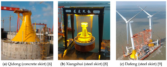
Figure 1.
Composite bucket foundation engineering application.
The load acting on the foundation of the offshore wind turbine can actually be decomposed into six components, namely three force components (V, H2, H3) along the coordinate axis and three torque components (T, M2, M3) rotating around the coordinate axis, and the coplanar three degrees of freedom loading (V, H, M) does not fully reflect the force characteristics. Figure 2 is a schematic diagram of the composite loading mode. The torque load transmitted from the rotating structure, such as the blades, cannot be ignored, considering the stable and safe operation of the offshore wind turbine.
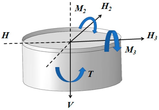
Figure 2.
Composite loading schematic diagram.
Houlsby [10] and Zhang [11] carried out in-situ tests and centrifuge model tests on suction foundations and tubular pile foundations respectively, and both of them suggested that the foundation is more susceptible to the instability failure under the action of the torque load or the load component, including the torque load.
At present, more achievements have been made in the study of torsion load for individual piles. Stoll et al. [12] presented a simplified field torque shear load test, and the penetration depth of friction pile is determined according to the torque shear resistance measured during construction. The results show that in practical engineering, the ultimate bearing capacity of pile foundation under torque load is often improved by increasing pile length, and analysis of the envelope of foundation failure under combined loading is the key to evaluate the ultimate bearing capacity of the foundation. McVey et al. [13] found a coupling relationship between horizontal force and torque through a single pile model test in sand. Three single piles with different length to diameter ratios are embedded in the sandy soil, and the horizontal force and torque are applied to the top of the pile through the force arm device, and the ratio is controlled. The results show that the horizontal force has less influence on the torque-bearing capacity of pile body, while the torque has a greater effect on the horizontal bearing capacity of pile body; the horizontal bearing capacity of the pile body is greatly affected by the aspect ratio, due to the presence of the torque. Taibat et al. [14,15] presents the results of three-dimensional analyses of circular foundations on the surface of homogeneous cohesive soil. The predicted ultimate response of the foundations to combined vertical, moment and horizontal loading was compared with other available theoretical predictions, and an equation that approximates the shape of the failure locus is also provided. The offshore wind turbine foundation is embedded in the saturated marine soil for a long time which is mostly layered soils, and the soil parameters have a great influence on the bearing characteristics of the wind turbine foundation. Hache [16] proposed a simple mathematical solution for a torsionally loaded pile in a layered soil based on Randolph’s [17] simplified elastic model and the Winkler approximation theory [18]. They found that for stiff piles, the torsional response dependent on the ratio of length and diameter, and non-dimensional charts for two-layered soil are presented. Chow [19] considered the stratification characteristics of the foundation soil and analyzed the single pile torsion problem of the double-layer soil by using the pile micro-segment balance method and the discrete element method. Guo et al. [20,21] used micro-segment equilibrium method and shear displacement method to derive the solution of the elastic and plastic phase of pile-side soil in single-layer and double-layer conditions based on the assumed shear modulus and ultimate friction distribution of pile-side soil.
As a new type of offshore foundation structure, CBF has its own features in configuration and installation method. The constitutive relationship and the failure mechanism of soil condition have some uncertainty. Most of the researches on suction foundations are based on the failure mode and the ultimate bearing capacity under vertical load [22], horizontal load, bending moment [23] and uplift load [24]. However, previous research has failed to consider the influence of the torque load. Based on the bucket foundation of an offshore wind turbine, in this paper, we investigate the bearing capacity of the bucket foundation under the torque load of layered soils. The stress distribution of the bucket foundation with different height of skirt, the different friction coefficient of soil-bucket and different diameter of the bucket foundation is analyzed; and in the last section, combined with the fixed displacement ratio loading method, the bearing capacity characteristics of the bucket foundation under different combined loading are analyzed.
2. Finite Element Model and Verification
2.1. Finite Element Model
The finite element method (FEM) can be used as an effective instrument to deal with various complex geotechnical engineering problems, and it can be used to evaluate the bearing capacity of the bucket foundations under different loads [25]. A three-dimensional finite element method for the bearing capacity behavior of CBF is established by using the universal finite element analysis software ABAQUS [26], as shown in Figure 3.
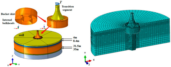
Figure 3.
Finite element model.
The foundation structure mainly includes a circular bucket, a middle concrete cover and an upper arc transition section. The lower cylinder is inserted into the soil, and the bucket skirt and the bucket lid share the upper load. A steel plate and a concrete roof are arranged on the upper part of the bucket lid, and the top plate is in the form of a composite beam plate. The design of the top plate and the upper transition section is used to transfer the upper load. The top of the transition section is connected to the bottom of the tower through an enlarged connection. The transition section adopts the prestressed reinforced concrete. The top plate is made of pressed steel reinforced concrete, and steel structure is used in bucket skirt and bucket lid. The bucket lid thickness is 100 mm, and the bucket skirt’s thick is 250 mm, which is the common thickness of the CBF in practice. The material properties of the concrete and the steel bucket are C60 and Q345, respectively. The CBF is assumed to be an ideal elastoplastic model; its Young’s modulus is E = 2.1 × 10⁵ MPa and a Poison’s ratio of ν = 0.3.
FEM was carried out on a bucket foundation installed in layered soil. The soil around the model is a cylinder with a diameter of 150 m and a height of 50 m to avoid the boundary condition effect and to achieve more accurate results. Displacements in all directions of the model boundaries (the bottom, all directions of periphery plus normal direction on the symmetry) were fixed, and it can be assumed as an elastic-plastic material in the FEM model combined with the Mohr-Coulomb failure criterion. The contact pair algorithm is employed to simulate the contact features of the interface between the foundation and the soil. Table 1 shows soil parameters.

Table 1.
Soil parameters.
2.2. Validation of the Model
In order to verify the applicability of the used numerical simulation method, a field trial studies in existing studies were considered.
A large-scale test at Frederikshavn employed a loading condition by applying a horizontal load at 17.4 m height, with a constant vertical load of 37.3 kN. A steel caisson with an outer diameter of 2 m and a skirt length of 2 m was installed in a shallow deep of 4 m lagoon next to the sea. The skirt was made of 12 mm thick steel plate. The soil consisted of very dense fine sand with a unit weight of 19.5 kN/m3 [25,27].
Figure 4 illustrates the comparison between the test results of the moment-rotation curve, with the predicted result obtained from the numerical analysis by ABAQUS. The Young’s modulus of sand is E = 30 MPa, and the internal friction angle is 30°, it can be seen that the calculated value of moment bearing capacity is very close to the experimental value.
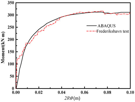
Figure 4.
Comparison between numerical and large-scale tests at Frederikshavn [28].
In addition, ABAQUS software has been used in many previous numerical simulations on the bearing capacity of the bucket foundations [6,7]. Therefore, the adopted numerical modeling can properly simulate the bucket foundation used for offshore wind turbines.
3. Stress Analysis of the Bucket Skirt under Torque Load
The foundation of offshore wind turbine is subjected to torque load under the action of rotating structures, such as blades. The torque load has some influence on the mechanical characteristics of the foundation.
3.1. Stress of the Bucket Skirt at Different Skirt Height under Torque Load
In this section, the effect of different skirt heights on the stress of the bucket skirt under torque load is described and analyzed. The soil is soft layer below 8.4 m in depth, and the depth of the bucket skirt is 7.4 m (above the soft soil layer), 8.4 m (at the soft soil layer), 9.4 m, 10.4 m, and 12 m (below the soft soil layer). There are no internal bulkheads. The displacement control loading method is used. A torsional angle of 0.01 rad is applied to the top of the transition section of foundation.
Figure 5 is the rotation-torque curves for bucket foundation with different heights of the skirt. It can be seen that, under the torsion angle of 0.01 rad, the torque-bearing capacity of the bucket foundation with a height of 7.4 m reaches the ultimate value. However, in other cases, it does not meet; when the skirt depth is 8.4 m, the bottom of the cylinder just reaches the top of the soft soil layer, therefore, it is less affected by the soft soil and has a larger bearing capacity. Then, the increase in the depth of the skirt entering the soft soil layer allows the ultimate bearing capacity of the foundation to increase, which means the bucket geometry and soil properties have a positive influence on the bearing capacity of the foundation under torque load.
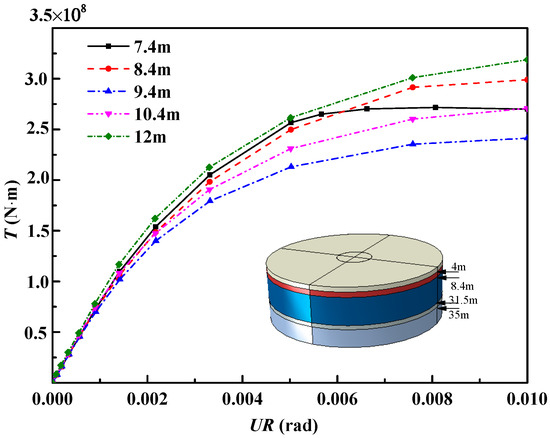
Figure 5.
The rotation-torque curves under different bucket skirt heights.
Figure 6 shows the contact stress of inside and outside soil on the bucket skirt at different depths with different skirt heights. Because the foundation is a symmetrical model, only X-direction is considered in this section. Figure 7 is a diagram depicting the damage done by plastic in to the soil. It can be seen that the plastic damage of the soil occurs at the bottom of the foundation under the torque load.
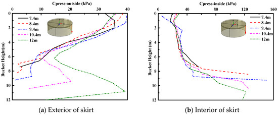
Figure 6.
Contact stress of skirt under different bucket skirt heights.
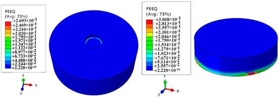
Figure 7.
Damage done by plastic in the soil.
As can be seen from Figure 6a, since the bucket lid bears part of the torque load, the contact stress of the skirt part near the bucket lid is larger when it is subjected to the outside soil. When the bottom of the skirt is above the soft soil layer, the normal stress of the outside soil on the wall of the skirt decreases gradually with the increase of the depth of the skirt into the soil. However, when the height of the bucket skirt is under soft soil, the normal contact stress of the bucket skirt tends to increase and the bucket skirt contact stress is reduced, due to the plastic failure of the soil near the bottom; The trend of contact stress between the outside soil and the bucket skirt under soft soil layer is an S-shaped curve. It can be seen that from Figure 6b that the contact stress between the inside soil and the bucket skirt increases slowly with the increase of the skirt height, when the skirt enters the soft soil layer, the contact stress between the inside soil and the bucket skirt increases rapidly.
Figure 8 demonstrates a comparison of the overall stress of the inside and outside soil on the wall of the cylinder under torque load with different skirt heights. It can be seen that, due to the large contact area between the bucket lid and the foundation soil, the wall of the foundation plays a restraining role. The inside soil and the bucket skirt share the torque load. The contact stress of the inside soil acting on the bucket skirt is greater than that of the outside soil. As the height of the skirt increases, the effect of the inside and outside soil on the bucket skirt increases. In comparison to the inside skirt, the contact stress on the outside skirt of the bucket is reduced by 32.9% when the height of the bucket skirt is 7.4 m, and the contact stress on the outside skirt of the bucket is reduced by 50.3% when the height of the bucket skirt is 12 m.
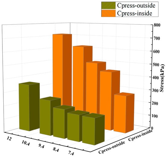
Figure 8.
Contact stress of skirt under different bucket skirt heights.
Figure 9 presents the shear stress of inside and outside soil at different depths of the bucket skirt. We can see that when the tip of the skirt is above the soft soil layer, the shear stress of the outside soil decreases as the depth of the soil increases. As the tip of the skirt is below the soft soil layer, the stress of the outside soil to the bucket skirt is an S-shaped. The shear stress of the inside soil increases as the increase of the depth that the skirt enters the soil.
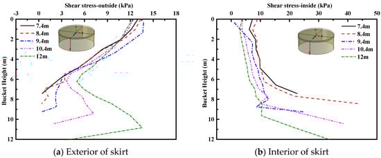
Figure 9.
Shear stress of skirt under different bucket skirt heights.
Figure 10 shows the normal contact stress of the bucker lid under torque load considering different skirt heights. With the height of the skirt increases, the normal stress on the center of the bucket lid of the suction foundation increases, and the normal contact stress on the bucket lid is symmetrical with respect to the center of the bucket lid.
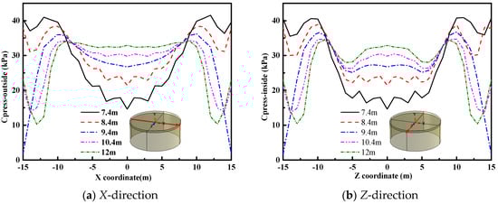
Figure 10.
Contact stress of the bucket lid under different bucket skirt heights.
Figure 11 illustrates the average rotation angle and the horizontal displacement of the suction foundation with different skirt heights under torque load. It can be seen that the average horizontal displacement of foundation increases with the increase of skirt height. Under the 0.01 rad torsion angle actioning on the top of the curved transition section, the average rotation angle of the base is 0.0075 rad.
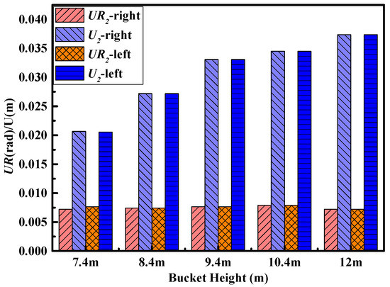
Figure 11.
Average rotation angle and horizontal displacement of the bucket foundation under different bucket skirt heights.
3.2. Stress of the Bucket Skirt under Torque Load with Different Friction Coefficient
The contact pair algorithm is used to simulate the interaction effects at the interface between the bucket and the soil. The tangential interaction between the interfaces uses Coulomb’s law of friction to describe the frictional properties. The interface is in a bonding state, which will slide relatively until the shear stress reaches the critical value. The normal interaction between the two interfaces uses hard contact [28]. The friction angle varies with the friction coefficient, and the friction angle is 20° when the friction coefficient is 0.35. The friction coefficient is closely related to the properties of soil, and it generally increases with the increase of soil strength. It is also related to the roughness of the contact surface. The seven rooms of the suction foundation are divided by bulkheads. The six peripheral rooms have the same proportions, and the middle one is a regular hexagonal structure. The height of the bucket is 12 m, and the height of the bulkhead is 10 m. The torsional angle of 0.02 rad is exerted on the top of the transition section, the coefficient of friction between bucket and soil is 0.35, 0.45 and 0.55, respectively. The influence of friction coefficient on stress distribution of the bucket skirt under torque load is studied considering whether bulkheads are used.
Figure 12 is the rotation-torque curves for bucket foundation under torque load with different friction coefficients. It can be seen that the friction coefficient has a greater impact on the bearing capacity for bucket foundations without bulkheads, and a smaller impact is shown in the case with bulkheads. Due to the combined action of the bulkheads and the bucket skirt, the restraint effect of soil is increased. The bearing capacity of the bucket foundation with the bulkheads under the same torque load is larger than that without the bulkheads.
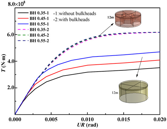
Figure 12.
The rotation-torque curves under different friction coefficients.
Figure 13 denotes the contact stress of inside and outside soil on bucket skirt at different depths under different friction coefficients. From Figure 13a, it can be seen that under the same torque load, the normal stress of the bucket skirt without bulkheads is greater than that of with bulkheads. The changing trend of stress on the bucket wall above the soft soil layer is the same for with and without the bulkheads conditions. With the increase of the depth of the soft soil layer, the normal stress of the outside soil to the bucket skirt increases and then abrupt decrease near the bottom of the cylinder. The bucket wall with bulkheads is not subject to the normal stress of the outside soil at a depth about 2–3 m from the bottom of the bucket. Figure 13b shows that under the same torque load, the stress of the inside soil on the bucket wall varies with the depth and the existence of the bulkhead. The difference in friction coefficient has less influence on the stress of the inside soil on the bucket skirt.
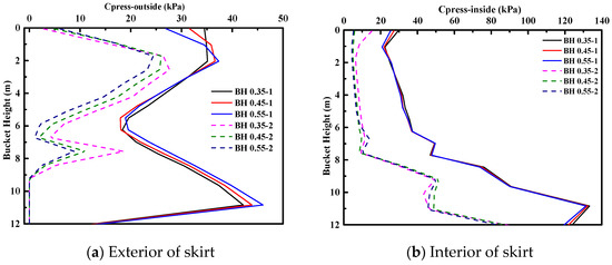
Figure 13.
Contact stress of skirt under different friction coefficients.
Figure 14 presents a comparison of the overall stress of the inside and outside soil on the bucket skirt under torque load with different friction coefficients. It can be seen that the interaction between the bucket and soil is strengthened when bulkheads exist. Regarding the bulkheads—the force acting on the inside and outside skirts of the bucket is greater than that on the case without bulkheads. When the friction coefficient increases, the total contact stress (inside and outside the soil) with bulkheads is gradually decreases. If the friction coefficient is 0.35, in comparison to the inside skirt, the contact stress on the outside bucket skirt (with and without bulkheads) is reduced by 48.7% and 53.5%, respectively.
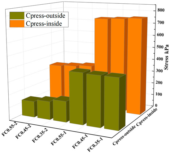
Figure 14.
Contact stress of skirt under different friction coefficients.
Figure 15 shows the shear stress of inside and outside soil on bucket skirt at different depths of the bucket skirt under different friction coefficients.
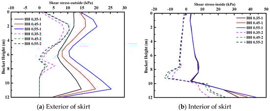
Figure 15.
Shear stress of skirt under different friction coefficients.
It can be seen that the influence of friction coefficient on the shear stress of the outside soil to bucket skirt is greater than that of the case with bulkheads. The stress of the outside soil to bucket wall increases with the increase of the friction coefficient when there are no bulkheads. The friction coefficient has little effect on the shear stress of the inside soil and the bucket skirt above the soft soil layer. Then, with the increase of friction coefficient, the shear stress of inside soil and bucket skirt increases around 1 m below soft soil layer and 2 m above bucket bottom. The coefficient of friction has a great influence on the shear stress when the bucket wall is in the soft soil and without the bulkheads.
Figure 16 shows the normal contact stress of the bucket lid of under torque load with different friction coefficients. It can be seen that the shear stress of the soil and the bucket lid has changed a little in the range of 2/3 of the center of the bucket lid at the X-direction. However, the shear stress of the soil and the bucket lid does not change much in the range of a third of the bucket lid center at the Z-direction.
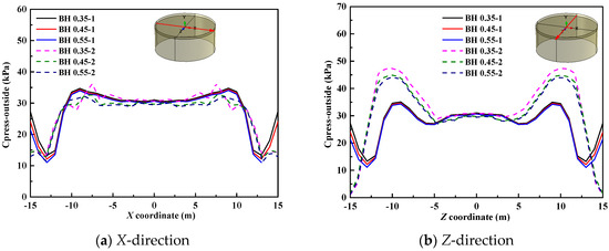
Figure 16.
Contact stress of the bucket lid under different friction coefficients.
Figure 17 is a vector diagram of the soil deformation and displacement when torsion angles of the bucket foundation are 0.005 rad, 0.01 rad and 0.02 rad, respectively, and the coefficient of friction is 0.35. It can be seen that there is a significant plastic zone in the soil outside the bucket skirt under the torque load, and the soil’s plastic zone is near the bottom of suction foundation without bulkheads. With the increase of the torque load, the plastic zone at the bottom diffuses to the middle of the soil. Under the same torque load, the soil deformation without bulkheads is larger than that with bulkheads, and the maximum difference of deformation decreases with the increase of torque load.
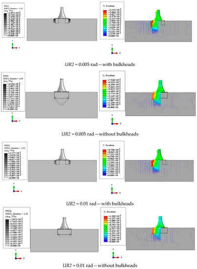
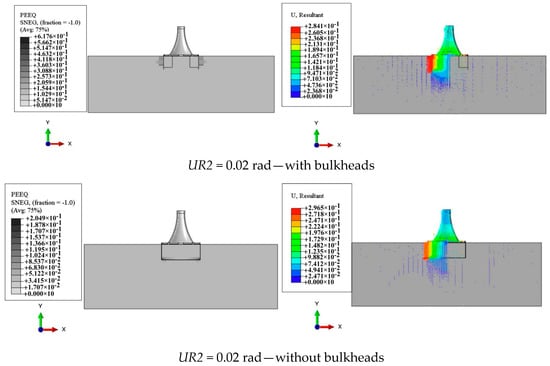
Figure 17.
Vector diagram of soil deformation and displacement.
3.3. Stress of the Bucket Skirt under Torque Load with Different Bucket Diameter
In this section, the effect of different bucket diameters on the stress of the bucket skirt under torque load is analyzed. The torsional angle of 0.02 rad is exerted on the top of the transition section of the foundation to analyze the bucket foundations with diameters of 30 m, 32 m and 35 m.
Figure 18 illustrates the contact stress of inside and outside soil on bucket skirt at different depths of the bucket skirt under different bucket diameters. It can be seen that the difference in the diameter of the cylinder has little effect on the stress of the inside and outside skirts. Under torque load, the contact stress of outside soil on the bottom of the bucket skirt is 0 without bulkheads, and the contact stress of the inside soil to the bucket skirt increases rapidly.
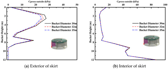
Figure 18.
Contact stress of skirt under different bucket diameter.
Figure 19 shows the shear stress of inside and outside soil on bucket skirt at different depths of the bucket skirt under different bucket diameters. The influence of inside and outside soil on the shear contact stress of the bucket skirt is small when the diameter of the bucket changes: The action of torque load, the shear stress of outside soil on the bottom of the bucket skirt without bulkheads is 0, the shear stress of the inside soil increases rapidly, and the trend of the normal contact stress is the same as that on the bucket wall.
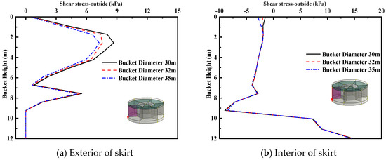
Figure 19.
Shear stress of skirt under different bucket diameter.
4. Bearing Capacity Characteristics of CBF under Different Loads
CBF is subjected to different loads in complex marine environments. The seven subdivision structures cause the deformation mechanism of the CBF more complicated to estimate the ultimate bearing capacity. This section studies the bearing capacity of CBF under different loads by the envelope method. The foundation has a diameter of 30 m, a height of 12 m and with bulkheads. The combined loading methods include the swipe loading method [29,30] and the fixed displacement ratio method [31]. The swipe method can directly search the general shape of the envelope of bearing capacity of foundation in load space, which is simple and fast. For the envelope with symmetry, the calculation results obtained by this method are more accurate. The fixed displacement ratio method can search the loading path of foundation in arbitrary load space, and can determine the envelope of bearing capacity of foundation in corresponding load space by multiple loading paths, which requires multiple calculations to obtain the loading path and finally to determine the envelope. However, this method has universal practicability for various loading modes and no requirement for symmetry [22]. The fixed displacement ratio method is used in this paper.
Figure 20 is the rotation-torque curves for CBF with different bucket diameters. It can be seen that the torsional bearing capacity of CBF increases with the increase of the bucket diameter. When the torsion angle is 0.018 rad, the ultimate bearing capacity of the CBF with a diameter of 30 m is 613 MN·m. As for the diameter of 35 m, the ultimate bearing capacity of the CBF with 0.021 rad torsion angle is 840 MN·m, which is 37% higher than that of the CBF with a diameter of 30 m.
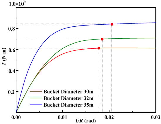
Figure 20.
The rotation-torque curves under different bucket diameter.
Randolph [17] obtained the relationship between torque and torsional rotation of the pile under torque load [32], as follows:
where, θ is the torsional rotation; G is the elastic shear modulus of the soil; R is the radius of the base; T is the torque load.
Cassidy [33] provided the relationship between torque and torsional rotation of shallow circular foundation (seen in Figure 21), as follows:
where, σmax is the maximum vertical stress; ϕ is the friction angle.
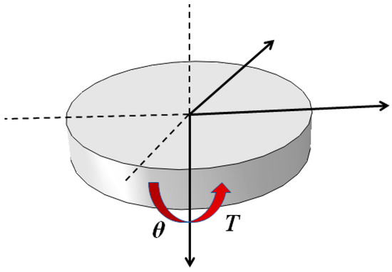
Figure 21.
Circular shallow foundation [33].
The CBF shares the torque load through the skirt and bucket lid. Calculate the torque load of the CBF in combination with Equations (1) and (2). T = T1 + T2. As the CBF is a wide-shallow foundation, it is different from the pile foundation. The torsional rotation in Equation (1) takes 2Rθ. The torque loads of the CBF with bucket diameters of 30 m, 32 m and 35 m are calculated to be 501 MN·m, 603 MN·m and 829 MN·m, respectively. Due to the influence of the bulkheads and the basic dimensions, the theoretical calculation results are 18.3%, 13.7% and 1.3% smaller than the numerical simulation results, and the results differed slightly.
The envelope curve of the ultimate bearing capacity of the CBF is described in H–T load Space, as shown in Figure 22. The increment ratio (Ra = δu/δDθ) are 0, 0.1, 0.25, 0.3, 0.5, 0.75, 0.85, ∞, respectively. Based on that, the failure envelope of the H–T bearing capacity of the bucket foundation is searched. It can be seen that as the horizontal force increases, the limit torque value decreases slowly, and when the horizontal force increases to a certain value, the torque value begins to decrease significantly.
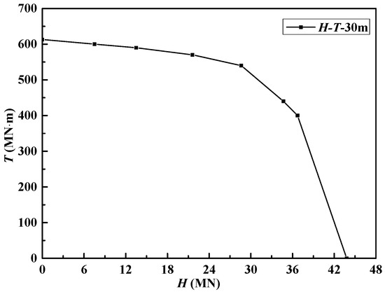
Figure 22.
Failure envelope in H–T load space.
In addition, the failure mechanisms of the bucket foundation under the vertical load V, horizontal load H, and torque load T are studied. The vertical load components (Vi) are taken as 0, 0.25, 0.5, 0.75, 0.85 and 1 Vult, respectively. Figure 23 shows the bucket foundation failure envelope under the V–H–T load. It can be seen that with the change of vertical load, the shape of H–T failure envelope of the bucket foundation shows no obvious change, and the vertical load has little effect on horizontal displacement and angular. Then, there is a increase of vertical load, and the horizontal and torsional bearing capacity decreases gradually.
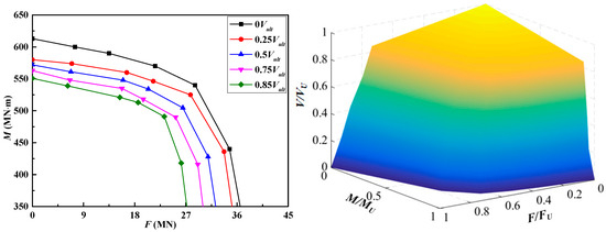
Figure 23.
Failure envelope in V–H–T load space under different vertical forces.
5. Conclusions
In this paper, the numerical simulation is used to study the bearing capacity characteristics of the CBF under the torque load of the layered soil. The contact stress and shear stress of the bucket skirt of the bucket foundation without a bulkhead subjected to the torque load at different skirt heights are analyzed. The results show that the contact stress of the inside soil acting on the bucket skirt is greater than that of the outside soil; as the height of the skirt increases, the effect of the inside and outside soil on the bucket skirt increases. The influence of friction coefficient on the bearing capacity of the bucket foundation under torque load is studied with and without a bulkhead. It is found that the friction coefficient has a greater impact on the bearing capacity of the bucket foundation without a bulkhead. At the same time, the effects of inside and outside soil on the wall of CBF with different diameters under torque load are developed, which presents that the change of diameter has little effect on the contact stress of the outside soil acting on the bucket skirt, but a greater influence on the inside skirt. Bucket geometry and soil properties significantly affect the contact stress of the skirt.
The basic bearing capacity characteristics of CBF under combined loads H–T and V–H–T were studied using the fixed displacement ratio loading method. The results show that the torque-bearing capacity decreases slowly with the increase of horizontal force. When the horizontal force increases to a certain value, the value of torque begins to decrease significantly. The shape of H–T failure envelope of the bucket foundation has no obvious change, and the vertical loads have less effect on horizontal and torque loads.
Author Contributions
Conceptualization, P.Z., H.D. and C.L.; Methodology, P.Z. and Y.L.; Software, Y.L. and C.L.; validation, P.Z., Y.L. and H.D.; Formal Analysis, Y.L. and P.Z.; Writing—Original Draft Preparation, Y.L. and P.Z.; Writing—Review & Editing, P.Z. and Y.L.; Supervision, H.D., C.L. and P.Z; Project administration, H.D. and P.Z; Funding acquisition, H.D., P.Z. and Y.L.
Funding
This research was funded by the National Natural Science Foundation of China (Grant Nos. 51779171 and 51779096), Innovation Method Fund of China (Grant No. 2016IM030100), the Tianjin Municipal Natural Science Foundation (Grant No. 17JCYBJC22000) and State Key Laboratory of Coastal and Offshore Engineering (Grant No. LP1709).
Conflicts of Interest
The authors declare no conflict of interest.
References
- Zhang, P.; Guo, Y.; Liu, Y.; Ding, H.; Le, C. Model tests on sinking technique of composite bucket foundations for offshore wind turbines in silty clay. J. Renew. Sustain. Energy 2015, 7, 033113. [Google Scholar] [CrossRef]
- Ding, H.; Liu, Y.; Zhang, P.; Le, C. Model tests on the bearing capacity of wide-shallow composite bucket foundations for offshore wind turbines in clay. Ocean Eng. 2015, 103, 114–122. [Google Scholar] [CrossRef]
- Zhang, P.; Ding, H.; Le, C. Seismic response of large-scale prestressed concrete bucket foundation for offshore wind turbines. J. Renew. Sustain. Energy 2014, 6, 013127. [Google Scholar] [CrossRef]
- Ding, H.; Liu, Y.; Zhang, P. Influential factors of bucket foundation for offshore wind turbine. Trans. Tianjin Univ. 2015, 21, 264–268. [Google Scholar] [CrossRef]
- He, S.; Zhang, P.; Ding, H. Study on the bearing mode and force transfer path of composite bucket foundations. Energies 2017, 10, 1041. [Google Scholar] [CrossRef]
- Zhang, P.; Hu, R.; Ding, H. Comparative analysis of seepage field characteristics in bucket foundation with and without compartments. Ocean Eng. 2017, 143, 34–49. [Google Scholar] [CrossRef]
- Ding, H.; Lian, J.; Li, A.; Zhang, P. One-step-installation of offshore wind turbine on large-scale bucket-top-bearing bucket foundation. Trans. Tianjin Univ. 2013, 19, 188–194. [Google Scholar] [CrossRef]
- Polaris Wind Power Network. The World’s First Offshore Wind Turbine Composite Cylinder Foundation Installation Completed. 2017. Available online: http://news.bjx.com.cn/html/20170207/806650.shtml (accessed on 7 February 2018).
- Polaris Wind Power Network. Successful Installation of the First Composite Bucket Foundation of Jiangsu Dafeng Project. 2018. Available online: http://news.bjx.com.cn/html/20180914/927971.shtml (accessed on 14 September 2018).
- Houlsby, G.T.; Kelly, R.B.; Huxtable, J.; Byrne, B.W. Field trials of suction caissons in clay for offshore wind turbine foundations. Geotechnique 2005, 55, 287–296. [Google Scholar] [CrossRef]
- Zhang, L.M.; Kong, L.G. Centrifuge modeling of torsional response of piles in sand. Can. Geotech. J. 2006, 43, 500–515. [Google Scholar] [CrossRef]
- Stoll, U.W. Torque shear test of cylindrical friction piles. Civ. Eng. 1972, 42, 63–65. [Google Scholar]
- McVay, M.C.; Hu, Z. Determine Optimum Depths of Drilled Shafts Subjected to Combined Torsion and Lateral Loads from Centrifuge Testing. 2003. Available online: https://trid.trb.org/view/679256.pdf (accessed on 20 December 2018).
- Taiebat, H.A.; Cater, J.P. Numerical studies of the bearing capacity of shallow foundation on cohesive soil subjected to combined loading. Geotechnique 2000, 50, 409–418. [Google Scholar] [CrossRef]
- Hu, C.; Zhang, T. Torsional vibration of pile in layered soils with considering soil-pile interaction. J. Earthq. Eng. Eng. Vib. 2009, 29, 138–146. [Google Scholar]
- Hache, R.A.G.; Valsangkar, A.J. Torsional resistance of single pile in layered soil. J. Geotech. Eng. 1988, 114, 216–220. [Google Scholar] [CrossRef]
- Randolph, M.F. Piles subjected to torsion. J. Geotech. Eng. Div. 1981, 107, 1095–1111. [Google Scholar]
- Winkler, D.A.; Le, T.C. Performance of deep and shallow Neural Networks, the Universal Approximation Theorem, Activity Cliffs, and QSAR. Mol. Inform. 2017, 36. [Google Scholar] [CrossRef]
- Chow, Y.K. Torsional response of piles in non-homogeneous soil. J. Geotech. Eng. 1985, 111, 942–947. [Google Scholar] [CrossRef]
- Guo, W.D.; Randolph, M.F. Torsional piles in non-homogeneous media. Comput. Geotech. 1996, 19, 265–287. [Google Scholar] [CrossRef]
- Guo, W.D.; Chow, Y.K.; Randolph, M.F. Torsional piles in two-layered nonhomogeneous soil. Int. J. Geomech. 2007, 7, 410–412. [Google Scholar] [CrossRef]
- Zhao, X.; Zhang, P.; Lv, Y. Scour effects on bearing capacity of composite bucket foundation for offshore wind turbines. Mar. Georesour. Geotech. 2019. [Google Scholar] [CrossRef]
- Liu, Y.; Guo, Y.; Ding, H.; Zhang, P. Failure envelopes of wide-shallow composite bucket foundation for offshore wind turbines in silty sand. Trans. Tianjin Univ. 2018, 24, 182–190. [Google Scholar] [CrossRef]
- Feng, X.; Pi, X.; Feng, S.; Bian, C. Research on the uplift bearing capacity of suction caisson Foundation under local tensile failure. Procedia Eng. 2016, 166, 61–68. [Google Scholar] [CrossRef]
- Bagheri, P.; Son, S.W.; Kim, J.M. Investigation of the load-bearing capacity of suction caissons used for offshore wind turbines. Appl. Ocean Res. 2017, 67, 148–161. [Google Scholar] [CrossRef]
- Simulia. ABAQUS User’s Manual; Dassault Systems Simulia Corp: Providence, RI, USA, 2017. [Google Scholar]
- Houlsby, G.T.; Ibsen, L.B.; Byrne, B.W. Suction caissons for wind turbines. Front. Offshore Geotech. 2005, 10, 1–6. [Google Scholar]
- Jia, N.; Zhang, P.; Liu, Y.; Ding, H. Bearing capacity of composite bucket foundations for offshore wind turbines in silty sand. Ocean Eng. 2018, 151, 1–11. [Google Scholar] [CrossRef]
- Tan, F.S.C. Centrifuge and Theoretical Modeling of Conical Footings on Sand. Ph.D. Thesis, Cambridge University, Cambridge, UK, 8 May 1990. [Google Scholar]
- Martin, C.M. Physical and Numerical Modeling of Offshore Foundations under Combined Loads. Ph.D. Thesis, The University of Oxford, Oxford, UK, 1994. Available online: http://www2.eng.ox.ac.uk/civil/publications/theses/martin.pdf (accessed on 20 December 2018).
- Supachawarote, C.; Randolph, M.F.; Gourvenec, S. Inclined pull-out capacity of suction caissons. In Proceedings of the 14th International Offshore and Polar Engineering Conference, Toulon, France, 23–28 May 2004. [Google Scholar]
- American Petroleum Institute. Petroleum and Natural Gas Industries—Specific Requirements for Offshore Structures—Part 4: Geotechnical and Foundation Design Considerations. Available online: http://www.doc88.com/p-1426698071331.html (accessed on 13 November 2014).
- Cassidy, M.J.; Cheong, J. The behaviour of circular footings on sand subjected to combined vertical-torsion loading. Int. J. Phys. Model. Geotech. 2005, 5, 1–14. [Google Scholar] [CrossRef]
© 2019 by the authors. Licensee MDPI, Basel, Switzerland. This article is an open access article distributed under the terms and conditions of the Creative Commons Attribution (CC BY) license (http://creativecommons.org/licenses/by/4.0/).