Prediction of Performance of a Variable-Pitch Axial Fan with Forward-Skewed Blades


Abstract
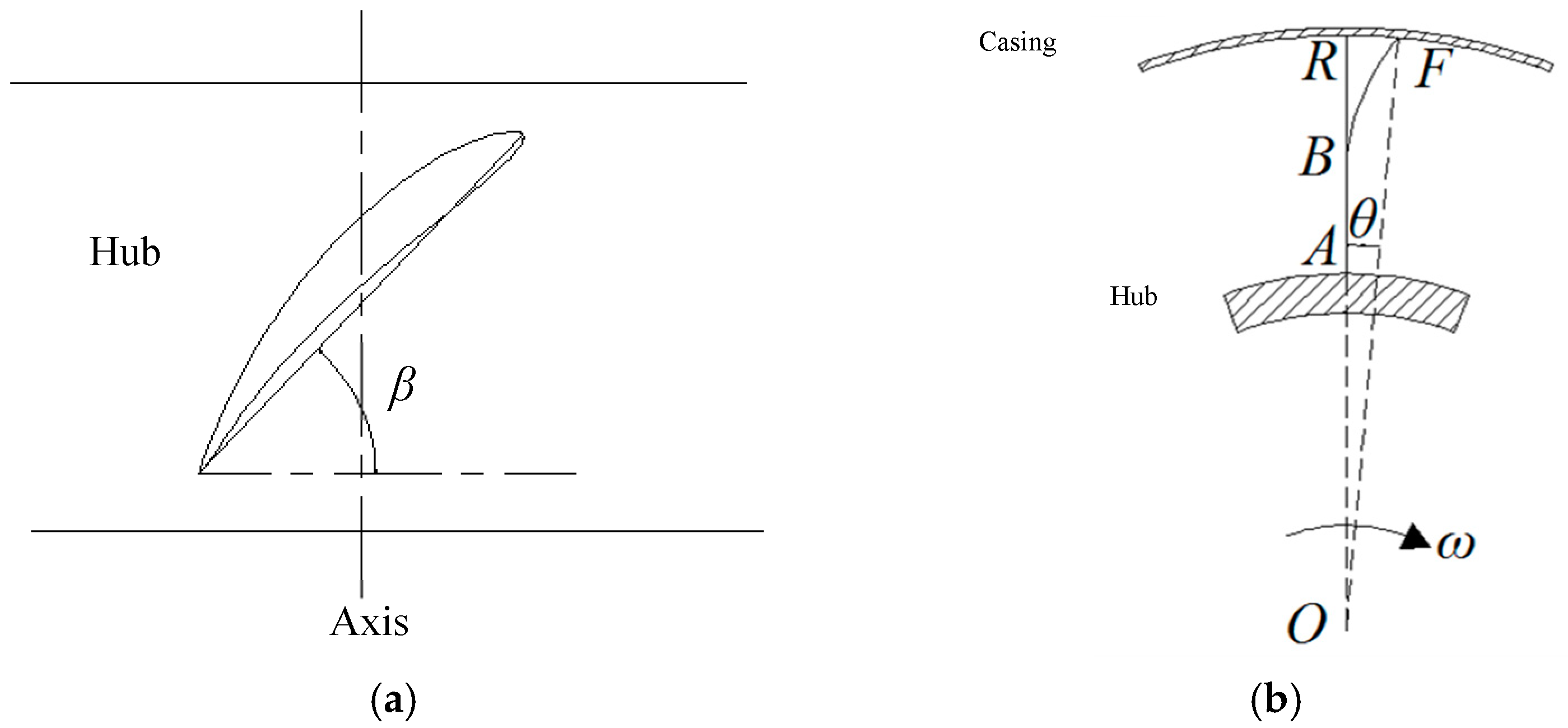
1. Introduction
2. Computational Model
2.1. Fan Model
2.2. Meshing
2.3. Numerical Method
- (1)
- (2)
- Turbulence model: considering the complex internal flow dynamics of axial flow fans and the evolution of different vortices, including the passage vortex, tip leakage vortex, scraping vortex, and wakes [30,31,32,33,34], the Realisable k–ε model that effectively simulates the complex flow in the tip clearance and the rotational motion is applied [1,2,19,35]. The SIMPLE algorithm is used to achieve the coupling of velocity and pressure [36]. The MRF (multiple reference frame) model, considering the interference at the interface between the rotating and stationary domains, is an efficient path to simulate steady flows in a short computation time; it is widely utilized in the fluid machinery applications [2,19]. Considering the complexity of data processing and the time required for the computation, the MRF model is employed for the coupling between the impeller and the casing in this study.
- (3)
- Domain division: four regions are involved. The impeller is defined as the rotating region with a rotating speed and rotation direction, and the bell mouth, guide vane, and diffuser are classified as the static region.
- (4)
- Boundary conditions: the inlet surface of the bell mouth and the outlet surface of the diffuser are referred to as the inlet and outlet of the entire flow field, respectively, using the velocity inlet and outflow outlet conditions. The inlet velocity is determined by the corresponding flow rate under a specific operating point and the outlet condition is uniformly set to free outflow. The turbulent kinetic energy and the turbulent dissipation rate of the inlet surface are calculated by substituting the average flow velocity and the characteristic length of the inlet cross-section into the empirical formula [37]. The surfaces of the impeller blade and hub are treated as the rotating surface, and the rest are treated as the static surfaces. The interface between adjacent regions is defined as the Interface, which is used for the coupling of data transmission and exchange. All walls adopt the no-slip boundary and the near wall region adopts a standard wall function.
2.4. Verification of Simulation
3. Results and Discussion
3.1. Fan Performance
3.2. Distribution of Axial Velocity Along Blade Height
3.3. Distribution of Axial Velocity at Different Blade Heights
3.4. Distribution of Static Pressure on Blade Surface
3.5. Distribution of Total Pressure Rise and Static Pressure Recovery Coefficients
3.6. Distribution of Specific Entropy Production Rate
3.7. Distribution of Specific Turbulent Kinetic Energy
4. Conclusions
Author Contributions
Funding
Conflicts of Interest
Nomenclature
| D | static pressure recovery coefficient of diffuser, D = 2(P2s − P1s)/ρu2 |
| P1s/P2s | static pressure of the inlet and outlet of guide vane, Pa |
| P1t/P2t | total pressure of the inlet and outlet of impeller, Pa |
| Pst | static pressure, Pa |
| Pt | total pressure rise, Pa |
| Qv | volume flow rate, m3·s−1 |
| r | radial blade height, mm |
| rh | hub radius, mm |
| rt | tip radius, mm |
| R | relative blade height, R = (r − rh)/(rt − rh) |
| SEPR | specific entropy production rate, W·kg−3·K−1 |
| STKE | specific turbulent kinetic energy, J·kg−1 |
| u | circumferential velocity of the blade tip, m·s−1 |
| υa | axial velocity, m·s−1 |
| β | blade angle, ° |
| η | total-to-total efficiency, % |
| θ | skewed angle, ° |
| ρ | gas density, kg·m−3 |
| Φ | total pressure rise coefficient of impeller, Φ = 2(P2t − P1t)/ρu2 |
References
- Li, C.; Li, X.; Li, P.; Ye, X. Numerical investigation of impeller trimming effect on performance of an axial flow fan. Energy 2014, 75, 534–548. [Google Scholar] [CrossRef]
- Ye, X.; Li, P.; Li, C.; Ding, X. Numerical investigation of blade tip grooving effect on performance and dynamics of an axial flow fan. Energy 2015, 82, 556–569. [Google Scholar] [CrossRef]
- He, W.; Dai, Y.; Han, D.; Yue, C.; Pu, W. Influence from the rotating speed of the windward axial fans on the performance of an air-cooled power plant. Appl. Therm. Eng. 2014, 65, 14–23. [Google Scholar] [CrossRef]
- Li, Y.; Ouyang, H.; Du, Z. Experimental research on aerodynamic performance and exit flow field of low pressure axial flow fan with circumferential skewed blades. J. Hydrodyn. 2007, 19, 579–586. [Google Scholar] [CrossRef]
- Vad, J.; Kwedikha, A.R.A.; Horváth, C.; Balczó, M.; Lohász, M.M.; Régert, T. Aerodynamic effects of forward blade skew in axial flow rotors of controlled vortex design. Proc. Inst. Mech. Eng. Part A J. Power Energy 2007, 221, 1011–1023. [Google Scholar] [CrossRef]
- Jin, G.; Ouyang, H.; Wu, Y.D.; Du, Z. Experimental and numerical investigations of the tip leakage flow of axial fans with circumferential skewed blades under off-design conditions. Proc. Inst. Mech. Eng. Part C J. Mech. Eng. Sci. 2010, 224, 1203–1216. [Google Scholar] [CrossRef]
- Jin, G.; Ouyang, H.; Du, Z. Experimental investigation of unsteady flow in axial skewed fans according to flow rates. Exp. Therm. Fluid Sci. 2013, 48, 81–96. [Google Scholar] [CrossRef]
- Jin, Y.; Liu, D.; Wen, Z. Optimization design for skew and sweep parameters of mine contra-rotating axial fan two-stage blades. J. China Coal Soc. 2010, 10, 1754–1759. [Google Scholar]
- Cai, N.; Li, D.; Zhong, F. Optimum design and experiment on skewed-swept rotating blades. J. Shanghai Jiaotong Univ. 1997, 31, 81–85. [Google Scholar]
- Ouyang, H.; Li, Y.; Du, Z.-H.; Zhong, F.-Y. Experimental study on aerodynamic and aero-acoustic performance of low pressure axial flow fan with circumferential skewed blades. J. Aerosp. Power 2006, 21, 668–674. [Google Scholar]
- Li, Y.; Ouang, H.; Du, Z. Optimized design based on skewed and swept blade technology. J. Eng. Therm. Energy Power 2007, 22, 605–611. [Google Scholar]
- Krömer, F.; Müller, J.; Becker, S. Investigation of aeroacoustic properties of low-pressure axial fans with different blade stacking. AIAA J. 2018, 56, 1507–1518. [Google Scholar] [CrossRef]
- Zhou, X.; Wang, S.; Wang, J. Study on aerodynamic performance of axial flow fan with bowed blade based on Bezier function. J. Huazhong Univ. Sci. Technol. Nat. Sci. Ed. 2013, 3, 106–109. [Google Scholar]
- Zenger, F.; Herold, G.; Becker, S. Acoustic characterization of forward- and backward-skewed axial fans under increased inflow turbulence. AIAA J. 2017, 55, 1241–1250. [Google Scholar] [CrossRef]
- Bamberger, K.; Carolus, T. Optimization of axial fans with highly swept blades with respect to losses and noise reduction. Noise Control Eng. J. 2012, 60, 716–725. [Google Scholar] [CrossRef]
- Beiler, M.; Carolus, T. Computation and measurement of the flow in axial flow fans with skewed blades. J. Turbomach. 1999, 121, 59–66. [Google Scholar] [CrossRef]
- Liu, Z.; Xiao, R.; Lü, T.; Li, S. Effect of swept blade on hump and cavitation characteristics of axial flow pump. J. Drainage Irrig. Mach. Eng. 2012, 3, 4. [Google Scholar]
- Xu, W.; Du, X.; Wang, S.; Wang, Z. Correlation of solidity and curved blade in compressor cascade design. Appl. Therm. Eng. 2018, 131, 244–259. [Google Scholar] [CrossRef]
- Starzmann, R.; Carolus, T. Effect of blade skew strategies on the operating range and aeroacoustic performance of the wells turbine. J. Turbomach. 2014, 136, 011003. [Google Scholar] [CrossRef]
- Li, C.; Lin, Q.; Ding, X.; Ye, X. Performance, aeroacoustics and feature extraction of an axial flow fan with abnormal blade angle. Energy 2016, 103, 322–339. [Google Scholar] [CrossRef]
- Zhang, L.; Zhang, L.; Zhang, Q.; Jiang, K.; Tie, Y.; Wang, S. Effects of the second-stage of rotor with single abnormal blade angle on rotating stall of a two-stage variable pitch axial fan. Energies 2018, 11, 3293. [Google Scholar] [CrossRef]
- Gou, Y.; Shi, X.; Zhou, J.; Qiu, X.; Chen, X. Characterization and effects of the shock losses in a parallel fan station in the underground mine. Energies 2017, 10, 785. [Google Scholar]
- Ye, X.; Zhang, J.; Li, C. Effect of blade tip pattern on performance of a twin-stage variable-pitch axial fan. Energy 2017, 126, 535–563. [Google Scholar] [CrossRef]
- Denton, J.D. The effect of lean and sweep on transonic fan performance: A computational study, Task quarterly. Propuls. Power Res. 2002, 6, 7–23. [Google Scholar]
- Mao, X.; Liu, B.; Zhao, H. Numerical analysis of the circumferential grooves casing treatment in a counter-rotating axial flow compressor. Appl. Therm. Eng. 2018, 130, 29–39. [Google Scholar] [CrossRef]
- Wang, Y.; Chen, W.; Wu, C.; Ren, S. Effects of tip clearance size on the performance and tip leakage vortex in dual-rows counter-rotating compressor. Proc. Inst. Mech. Eng. Part G J. Aerosp. Eng. 2015, 229, 1953–1965. [Google Scholar] [CrossRef]
- Zhang, L.; Wang, R.; Wang, S. Simulation of broadband noise sources of an axial fan under rotating stall conditions. Adv. Mech. Eng. 2015, 6, 507079. [Google Scholar] [CrossRef]
- Ghasemian, M.; Nejat, A. Aerodynamic noise prediction of a horizontal axis wind turbine using improved delayed detached eddy simulation and acoustic analogy. Energy Convers. Manag. 2015, 99, 210–220. [Google Scholar] [CrossRef]
- Zhu, X.; Hu, C.; Yang, X.; Du, Z. Dynamic mode decomposition analysis of the unsteady flow in a centrifugal compressor volute. J. Aerosp. Eng. 2019, 32, 04018136. [Google Scholar] [CrossRef]
- Han, S.; Zhong, J. Effect of blade tip winglet on the performance of a highly loaded transonic compressor rotor. Chin. J. Aeronaut. 2016, 29, 653–661. [Google Scholar] [CrossRef]
- Jung, Y.-J.; Jeon, H.; Jung, Y.; Lee, K.-J.; Choi, M. Effects of recessed blade tips on stall margin in a transonic axial compressor. Aerosp. Sci. Technol. 2016, 54, 41–48. [Google Scholar] [CrossRef]
- Kameier, K.; Neise, W. Experimental study of tip clearance losses and noise in axial turbomachines and their reduction. J. Turbomach. 1997, 119, 460–471. [Google Scholar] [CrossRef]
- Moghadam, S.M.A.; Meinke, M.; Schröder, W. Analysis of tip-leakage flow in an axial fan at varying tip-gap sizes and operating conditions. Comput. Fluids 2019, 183, 107–129. [Google Scholar] [CrossRef]
- Wu, Y.; An, G.; Wang, B. Numerical investigation into the underlying mechanism connecting the vortex breakdown to the flow unsteadiness in a transonic compressor rotor. Aerosp. Sci. Technol. 2019, 86, 106–118. [Google Scholar] [CrossRef]
- Lin, S.-C.; Tsai, M.-L. An integrated performance analysis for a backward-inclined centrifugal fan. Comput. Fluids 2012, 56, 24–38. [Google Scholar] [CrossRef]
- Zhou, X.; Zhao, Q.; Cui, W.; Xu, J. Investigation on axial effect of slot casing treatment in a transonic compressor. Appl. Therm. Eng. 2017, 126, 53–69. [Google Scholar] [CrossRef]
- Cui, J.; Ye, X.; Li, C. Simulation of casing treatment effect on the performance of an axial flow fan. J. Fluid Mach. 2016, 44, 11–17. [Google Scholar]
- Ghasemian, M.; Nejat, A. Aero-acoustics prediction of a vertical axis wind turbine using Large Eddy Simulation and acoustic analogy. Energy 2015, 88, 711–717. [Google Scholar] [CrossRef]
- Олoу Mahuo ребенкoм, T.C. Ventilator Pneumatic Schematic and Performance Curve; China Coal Ind. Press: Beijing, China, 1986; pp. 336–346. [Google Scholar]
- Ouyang, H. Study on a New Type Reversible Axial Flow Fan with Skewed and Combined Blades. Ph.D. Thesis, Shanghai Jiaotong University, Shanghai, China, 2003. [Google Scholar]
- Luan, H.; Weng, L.; Luan, Y.; Zhang, Y.; Chen, P. Numerical study on aerodynamic noise performances of axial spacing in a contra-rotating axial fan. J. Vibroeng. 2016, 18, 5605–5618. [Google Scholar]
- Galindo, J.; Tiseira, A.; Navarro, R.; López, M.A. Influence of tip clearance on flow behavior and noise generation of centrifugal compressors in near-surge conditions. Int. J. Heat Fluid Flow 2015, 52, 129–139. [Google Scholar] [CrossRef]
- Jung, J.H.; Joo, W.-G. Effect of tip clearance, winglets, and shroud height on the tip leakage in axial flow fans. Int. J. Refrig. 2018, 93, 195–204. [Google Scholar] [CrossRef]
- Herwig, H.; Kock, F. Direct and indirect methods of calculating entropy generation rates in turbulent convective heat transfer problems. Heat Mass Transf. 2007, 43, 207–215. [Google Scholar] [CrossRef]


| Rotating Machinery | Main Parameters | Skewed Angle | Suggested Angle | Conclusions | References |
|---|---|---|---|---|---|
| Axial fan | Rotation speed 1440 r/min; hub-tip ratio 0.35; tip diameter 500 mm; tip clearance/span 1.5% | Original blade:1.27°; skewed blade: +8.3°, −8.3° | +8.3° | Reduced the total pressure loss | Li et al. [4] |
| Rotation speed 416 r/min; hub-tip ratio 0.6; tip diameter 2000 mm; tip clearance 7.2 mm | Skew angle at different fraction of span: 0.5mid:0.3°, 0.75:1.6°, 1.00tip:3.5° | Improved blade performance | Vad et al. [5] | ||
| Rotor speed 1440 r/min; tip radius 2475 mm; hub-tip ratio 0.35; tip clearance/span 1% | +8.3°, −8.3° | +8.3° | Reduced noise sources in the tip clearance region | Jin et al. [6,7] | |
| Rotor speed 980 r/min; hub-tip ratio 0.6; tip diameter 1600 mm | First stage impeller skewed angle −15°~15°; secondary impeller angle −12°~12° | First stage impeller +6.6°; secondary impeller −10.08° | Increased efficiency by 1.67%; improved flow in hub | Jin [8] | |
| Tip diameter 600 mm; hub-tip ratio 0.4 | −12°~24° | 8–10° | Increased efficiency by 3.2%; Reduced noise by 4.5 dB | Cai et al. [9] | |
| Rotation speed 1440 r/min; hub-tip ratio 0.35; tip diameter 500 mm; tip clearance/span 1.5% | Original blade:1.27°; skewed blade: +8.3°, −8.3° | +8.3° | Increased the stall margin by 6%; reduced noise by 4–5 dB | Ouyang et al. [10] | |
| Rotation speed 1500 r/min; tip diameter 495 mm; tip clearance 2.5 mm | Reduced sound source strength | Krömer et al. [12] | |||
| Rotation speed 839 r/min; tip diameter 401 mm; hub-tip ratio 0.25 | Improved flow performance; reduced noise by 1.1 dB | Zhou et al. [13] | |||
| Tip diameter 1500 mm; hub-tip ratio 0.6; tip clearance 4.5 mm; rotation speed 1200 r/min | +1.0°, +2.0°, +3.0°, +4.0°, +6.0°, +8.3° | 3.0° | Increased total pressure rise and efficiency; reduced acoustic noise | Present study | |
| Axial flow pump | Rotation speed 7800 r/min; tip diameter 70 mm | Suppressed the secondary flow and reduced energy loss | Liu et al. [17] | ||
| Compressor | Blade height 16 mm; chord 128 mm; hub-tip ratio 1.25; camber angle 36.31° | 0°, 5°, 10°, 15°, 20°, 25°, 30° | Reduced loss; recovered diffusion caused by lower solidity | Xu et al. [18] | |
| Water turbine | Rotation speed 4000 r/min; tip diameter 400 mm; hub-tip ratio 0.43 | +15°, −15°, −15° at hub and +5° at tip | +15° | Delayed stall occurrence; increased stall margin; reduced noise by 3 dB. | Starzmann and Carolus [19] |
| Number of impeller blades and guide vanes | 14, 15 |
| Diameter at the tip, mm | 1500 |
| Hub-tip ratio | 0.6 |
| Tip clearance, mm | 4.5 |
| Rotation speed, r·min−1 | 1200 |
| Volumetric flow rate, m3·s−1 | 37.14 |
| Total pressure rise, Pa | 2348 |
| Installation angle, ° | 32 |
| Meshing Number/million | Total Pressure Rise/Pa | Efficiency/% | Time/h |
|---|---|---|---|
| 3.82 | 2316.43 | 81.052 | 9.8 |
| 4.26 | 2325.95 | 81.237 | 10.2 |
| 4.65 | 2333.55 | 81.506 | 10.6 |
| 5.33 | 2333.82 | 81.509 | 11.5 |
| 5.56 | 2333.96 | 81.510 | 12.6 |
| Blade Angle/° | Qv/(m3·s−1) | Variation of Pt/% | Qv/(m3·s−1) | Variation of η/% |
|---|---|---|---|---|
| β = 29 | 29.98–43.3 | −1.34 | 29.98–31.00 | −0.04 |
| 31.00–43.30 | 0.95 | |||
| β = 32 | 33.31–33.50 | −0.11 | 33.31–34.00 | −0.37 |
| 34.00–37.14 | 0.34 | |||
| 33.50–46.63 | 2.23 | 37.14–46.00 | −1.55 | |
| 46.00–46.63 | 0.95 | |||
| β = 35 | 33.31–41.64 | −0.38 | 33.31–35.00 | −0.34 |
| 41.64–48.30 | 2.59 | 35.00–48.30 | 2.72 |
© 2019 by the authors. Licensee MDPI, Basel, Switzerland. This article is an open access article distributed under the terms and conditions of the Creative Commons Attribution (CC BY) license (http://creativecommons.org/licenses/by/4.0/).
Share and Cite
Ye, X.; Fan, F.; Zhang, R.; Li, C. Prediction of Performance of a Variable-Pitch Axial Fan with Forward-Skewed Blades. Energies 2019, 12, 2353. https://doi.org/10.3390/en12122353
Ye X, Fan F, Zhang R, Li C. Prediction of Performance of a Variable-Pitch Axial Fan with Forward-Skewed Blades. Energies. 2019; 12(12):2353. https://doi.org/10.3390/en12122353
Chicago/Turabian StyleYe, Xuemin, Fuwei Fan, Ruixing Zhang, and Chunxi Li. 2019. "Prediction of Performance of a Variable-Pitch Axial Fan with Forward-Skewed Blades" Energies 12, no. 12: 2353. https://doi.org/10.3390/en12122353
APA StyleYe, X., Fan, F., Zhang, R., & Li, C. (2019). Prediction of Performance of a Variable-Pitch Axial Fan with Forward-Skewed Blades. Energies, 12(12), 2353. https://doi.org/10.3390/en12122353